EP1915935A1 - Haendetrockner - Google Patents
Haendetrockner Download PDFInfo
- Publication number
- EP1915935A1 EP1915935A1 EP05772580A EP05772580A EP1915935A1 EP 1915935 A1 EP1915935 A1 EP 1915935A1 EP 05772580 A EP05772580 A EP 05772580A EP 05772580 A EP05772580 A EP 05772580A EP 1915935 A1 EP1915935 A1 EP 1915935A1
- Authority
- EP
- European Patent Office
- Prior art keywords
- slit
- air nozzle
- ejecting holes
- pressure
- front side
- Prior art date
- Legal status (The legal status is an assumption and is not a legal conclusion. Google has not performed a legal analysis and makes no representation as to the accuracy of the status listed.)
- Granted
Links
- 238000001035 drying Methods 0.000 claims abstract description 48
- 238000010276 construction Methods 0.000 abstract description 8
- 210000004247 hand Anatomy 0.000 description 34
- 238000001514 detection method Methods 0.000 description 8
- 230000033001 locomotion Effects 0.000 description 5
- 230000000694 effects Effects 0.000 description 4
- 238000005516 engineering process Methods 0.000 description 3
- 230000001105 regulatory effect Effects 0.000 description 2
- 230000000452 restraining effect Effects 0.000 description 2
- 238000005452 bending Methods 0.000 description 1
- 230000006698 induction Effects 0.000 description 1
- 238000000034 method Methods 0.000 description 1
- 238000005192 partition Methods 0.000 description 1
- 238000011064 split stream procedure Methods 0.000 description 1
- 238000011144 upstream manufacturing Methods 0.000 description 1
- XLYOFNOQVPJJNP-UHFFFAOYSA-N water Substances O XLYOFNOQVPJJNP-UHFFFAOYSA-N 0.000 description 1
- 210000000707 wrist Anatomy 0.000 description 1
Images


Classifications
-
- A—HUMAN NECESSITIES
- A47—FURNITURE; DOMESTIC ARTICLES OR APPLIANCES; COFFEE MILLS; SPICE MILLS; SUCTION CLEANERS IN GENERAL
- A47K—SANITARY EQUIPMENT NOT OTHERWISE PROVIDED FOR; TOILET ACCESSORIES
- A47K10/00—Body-drying implements; Toilet paper; Holders therefor
- A47K10/48—Drying by means of hot air
-
- A—HUMAN NECESSITIES
- A61—MEDICAL OR VETERINARY SCIENCE; HYGIENE
- A61H—PHYSICAL THERAPY APPARATUS, e.g. DEVICES FOR LOCATING OR STIMULATING REFLEX POINTS IN THE BODY; ARTIFICIAL RESPIRATION; MASSAGE; BATHING DEVICES FOR SPECIAL THERAPEUTIC OR HYGIENIC PURPOSES OR SPECIFIC PARTS OF THE BODY
- A61H33/00—Bathing devices for special therapeutic or hygienic purposes
- A61H33/06—Artificial hot-air or cold-air baths; Steam or gas baths or douches, e.g. sauna or Finnish baths
- A61H33/08—Air douches for hygienic purposes
-
- A—HUMAN NECESSITIES
- A61—MEDICAL OR VETERINARY SCIENCE; HYGIENE
- A61H—PHYSICAL THERAPY APPARATUS, e.g. DEVICES FOR LOCATING OR STIMULATING REFLEX POINTS IN THE BODY; ARTIFICIAL RESPIRATION; MASSAGE; BATHING DEVICES FOR SPECIAL THERAPEUTIC OR HYGIENIC PURPOSES OR SPECIFIC PARTS OF THE BODY
- A61H9/00—Pneumatic or hydraulic massage
- A61H9/005—Pneumatic massage
Definitions
- the present invention relates to a hand drying apparatus that sanitarily dries wet hands after being washed by ejecting high-speed airflows.
- Hand drying apparatuses that perform sanitary hand drying have been developed. These hand drying apparatuses blow moisture off by ejection of high-speed airflows to dry wet hands after being washed without wiping the hands with a towel or handkerchief. These types of hand drying apparatuses use kinetic energy of the high-speed airflows to blow moisture adhering to hands off. Therefore, collisions between opposite jet flows cause turbulence and produce noise.
- one nozzle is provided with slit-shaped ejecting holes and an opposite nozzle is provided with circular ejecting holes roughly arranged in respective lines. Therefore, turbulence caused by collisions between the opposite jet flows is reduced, thereby suppressing noise.
- Patent Document 1 Japanese Patent Application Laid-Open No. 2001-104212
- the present invention has been devised in view of the circumstances, and an object thereof is to obtain a hand drying apparatus that can prevent noise without employing a complicated construction and realize high drying performance and excellent usability.
- a hand drying apparatus includes a main body box case that has a hand inserting portion formed in a concave shape at an upper portion; a high-pressure airflow generator that generates high-pressure airflows and is included in the main body box case; and a front side air nozzle and a back side air nozzle that eject the high-pressure airflows generated by the high-pressure airflow generator into the hand inserting portion and face each other, wherein the front side air nozzle and the back side air nozzle are formed by a plurality of slit-shaped ejecting holes arranged in a line, respectively, and both or any one of lengths and arranging intervals of the slit-shaped ejecting holes is different between a front side and a back side.
- a hand drying apparatus includes a main body box case that has a hand inserting portion formed in a concave shape at an upper portion; a high-pressure airflow generator that generates high-pressure airflows and is included in the main body box case; and a front side air nozzle and a back side air nozzle that eject the high-pressure airflows generated by the high-pressure airflow generator into the hand inserting portion and face each other, wherein the front side air nozzle and the back side air nozzle are formed by a plurality of slit-shaped ejecting holes arranged in a line, respectively, and the slit-shaped ejecting holes on a front side are formed to be longer than the slit-shaped ejecting holes on a back side so that regions with different lengths where high-pressure airflows facing each other collide are formed on both sides of a region where the high-pressure airflows do not collide.
- a hand drying apparatus includes a main body box case that has a hand inserting portion formed in a concave shape at an upper portion; a high-pressure airflow generator that generates high-pressure airflows and is included in the main body box case; and a front side air nozzle and a back side air nozzle that eject the high-pressure airflows generated by the high-pressure airflow generator into the hand inserting portion and face each other, wherein the front side air nozzle and the back side air nozzle are formed by a plurality of slit-shaped ejecting holes arranged in a line, respectively, and an arranging interval of the slit-shaped ejecting holes on a front side are formed to be shorter than an arranging interval of the slit-shaped ejecting holes on a back side so that regions with different lengths where high-pressure airflows facing each other collide are formed on both sides of a region where the high-pressure airflows do not collide.
- the front side air nozzle and the back side air nozzle are formed by a plurality of slit-shaped ejecting holes arranged in a line, respectively, and both or any one of lengths of the slit-shaped ejecting holes and arranging intervals of the slit-shaped ejecting holes is different between the front side and the back side. Accordingly, it is possible to obtain a hand drying apparatus that can prevent noise without employing a complicated construction and realize high drying performance and excellent usability.
- the front side air nozzle and the back side air nozzle are formed by a plurality of slit-shaped ejecting holes arranged in a line, respectively, and the slit-shaped ejecting holes on the front side are formed to be longer than the slit-shaped ejecting holes on the back side so that regions with different lengths where high-pressure airflows facing each other collide are formed on both sides of a region where the high-pressure airflows do not collide. Accordingly, without employing a complicated construction, noise can be prevented, drying performance and usability are improved, and a palm and a back of a hand can be dried in a balanced manner.
- the front side air nozzle and the back side air nozzle are formed by a plurality of slit-shaped ejecting holes arranged in a line, respectively, and the arranging interval of the slit-shaped ejecting holes on the front side are formed to be shorter than the arranging interval of the slit-shaped ejecting holes on the back side so that regions with different lengths where high-pressure airflows facing each other collide are formed on both sides of a region where the high-pressure airflows do not collide. Therefore, without employing a complicated construction, noise can be prevented, drying performance and usability are improved, and a palm and a back of a hand can be dried in a balanced manner.
- Fig. 1 shows an external appearance of a hand drying apparatus of the present embodiment.
- this hand drying apparatus has a main body box case 1 that forms an outer sheath, having a hand inserting portion 3 on an upper portion.
- the hand inserting portion 3 is formed, which is a concave space formed by a hand inserting port 4 and a drying space 5 continued to the hand inserting port 4.
- the hand inserting portion 3 has a sink shape that is open at both sides and deep and inclined so that hands can be inserted and pulled out in a diagonally vertical direction, while both hands are aligned within a plane.
- a high-pressure airflow generator 2 is installed inside the main body box case 1.
- High-pressure airflows generated by the high-pressure airflow generator 2 are guided to air nozzles 6a and 6b provided on a front wall face and a back wall face of the hand inserting portion 3 via an air duct (not shown) bifurcated to a front side and a back side of the hand inserting portion 3.
- air duct (not shown) bifurcated to a front side and a back side of the hand inserting portion 3.
- high-speed airflows are ejected from these opposite air nozzles 6a and 6b into the hand inserting portion 3 to blow moisture adhering to hands inserted in the hand inserting portion 3 into the drying space 5.
- the blown-off moisture is collected by a drain receptacle having an inclined bottom in the concave space, and the collected water is stored in a drain tank 20 via a drain outlet (not shown) and a cesspipe (not shown), at an inclined lower end.
- the drain tank 20 is detachably attached to the main body box case 1, and is provided with a detachable cover.
- the high-pressure airflow generator 2 includes a direct current (DC) brushless motor (or a normal commutator motor or an induction motor), a drive circuit that drives this motor, and a turbo fan that is rotated by the DC brushless motor.
- DC direct current
- the high-pressure airflow generator 2 is attached below the hand inserting portion 3 of the main body box case 1, and is automatically driven by a control circuit (not shown).
- the air inlet side of the high-pressure airflow generator 2 faces an intake passage provided inside the main body box case 1 so as to suck in air from outside via an air inlet port at the end of the intake passage.
- a hand detection sensor 9 is provided on the wall face forming the drying space 5. Based on a detection signal of the hand detection sensor 9, presence of a hand inserted in the drying space 5 via the hand inserting portion 3 is detected. The detection signal of the hand detection sensor 9 is inputted into the control circuit equipped with a microcomputer. When the control circuit judges that a hand has been inserted, the high-pressure airflow generator 2 is energized to make high-speed airflows to blow out from the air nozzles 6a and 6b.
- the hand detection sensor 9 detects the hands.
- the high-pressure airflow generator 2 starts in response to processing of the control circuit.
- High-speed airflows 8a and 8b are blown into the hand inserting portion 3 from the air nozzles 6a and 6b and hit the palms and backs of the inserted hands to blow moisture adhering to the hands toward the bottom side of the hand inserting portion 3.
- waterdrops adhering to the entire hands is completely removed so that the hands are dried.
- the hand detection sensor 9 After drying the hands, when the hands are completely pulled out from the hand inserting portion 3, the hand detection sensor 9 detects this and the high-pressure airflow generator 2 stops. Waterdrops blown off from the hands adhere to the inner wall face of the hand inserting portion 3, but successively flow down to the bottom via the drain port and the cesspipe and are then stored in the drain tank 20.
- Fig. 2 is a conceptual front view from the front side of the air nozzle 6a on the front side and the air nozzle 6b on the back side disposed oppositely to each other.
- Both the air nozzles 6a and 6b of the present embodiment have a plurality of slit-shaped ejecting holes 7a and 7b arranged in a line, respectively, at both the front side and the back side. In this case, a line form bent at the center is employed.
- the slit-shaped ejecting holes 7a and 7b are inclined downward so that the high-speed airflows 8a and 8b are ejected slightly downward.
- the air nozzle 6a on the front side and the air nozzle 6b on the back side are formed so that, as shown in Fig. 2 , lengths La of the slit-shaped ejecting holes 7a on the front side and lengths Lb of the slit-shaped ejecting holes 7b on the back side are different, and arranging intervals Ca between the slit-shaped ejecting holes 7a on the front side and arranging intervals Cb between the slit-shaped ejecting holes 7b on the back side are different.
- the lengths of the slit-shaped ejecting holes are set so as to satisfy La>Lb, and the arranging intervals of the slit-shaped ejecting holes are set so as to satisfy Ca ⁇ Cb.
- the lengths La and the arranging intervals Ca of the slit-shaped ejecting holes 7a are the same, and at the air nozzle 6b on the back side, the lengths Lb and the arranging intervals Cb of the slit-shaped ejecting holes 7b are the same.
- Fig. 3 is a sectional view of one slit-shaped ejecting hole 7a or 7b.
- a plurality of concave portions 10 (and convex portions 11) extending in the airflow directions are formed, and these generate small turbulence of the airflows.
- a plurality of concave portions 10 and convex portions 11 are formed on the inner side of the upper and lower wall faces forming the slit-shaped ejecting holes 7, a plurality of concave portions 10 and convex portions 11 are formed.
- the slit-shaped ejecting holes 7 in order to prevent deformation of nozzles due to internal pressure and suppress turbulence inside the nozzles, it is typical to properly divide the length of the ejecting holes 7.
- a dividing method a plurality of separate nozzles is formed or ribs to become partitions are installed inside a single nozzle, and both cases have equivalent effects.
- wall face flows 15 perpendicular to the length of the ejecting holes are formed. This is because the streams of the airflows in the longitudinal direction of the ejecting holes are regulated.
- the wall face flows 15 are formed in the longitudinal direction only at the longitudinal ends, where they are not regulated. Therefore, in the case of the slit-shaped ejecting holes 7, the stagnation region 16 generated between the adjacent ejecting holes is much smaller compared to in the case of the circular holes 50. As a result, a smaller amount of moisture remains on the hands compared to in the case of the circular holes 50, realizing high drying efficiency.
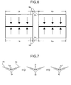
- This series of self-excited vibrations become a pressure fluctuation, fluctuate the split streams below the collisions point, propagate to the entirety of the film-like jet flows shown in Fig. 6 , and cause large-scale turbulence having jet stream lengths and a pressure fluctuation. Since the pressure fluctuation produces loud noise, this makes users uncomfortable. If the fluctuation becomes larger in scale, the pressure fluctuation propagates in jet stream directions inside the jet flows and may reach the high-pressure airflow generator 2 via the air nozzle 6 on the upstream side. In this case, the pressure to be discharged from the high-pressure airflow generator 2 also fluctuates. Therefore, this fluctuation links to the collisions point of the jet stream from the air nozzle 6, forms a feedback loop over the entirety of the discharge system, and may cause pulsatory motion involving a large-scale pressure fluctuation and damage the high-pressure airflow generator 2.
- the slit-shaped ejecting holes 7 are formed so that the lengths La of the slit-shaped ejecting holes 7a on the front side and the lengths Lb of the slit-shaped ejecting holes 7b on the back side are different, and the arranging intervals Ca between the slit-shaped ejecting holes 7a on the front side and the arranging intervals Cb between the slit-shaped ejecting holes 7b on the back side are different.
- regions 13 and 14 with different lengths where facing jet flows collide are formed on both sides so as to sandwich a region 12 where the facing jet flows do not collide. Therefore, the pressure fluctuating portions 13 and 14 with shifted phases are alternately sandwiched by the regions 12 that have no pressure fluctuations, so that the noise is smoothed and occurrence of noise can be restrained, as shown in Fig. 10 .
- the length La of the slit-shaped ejecting holes 7a on the front side is set longer than the length Lb of the slit-shaped ejecting holes 7b on the back side.
- the palm sides of hands have a large amount of moisture in the horny layer of the skin, and are therefore more difficult to dry than the back sides of hands. Therefore, by increasing the force of the jet stream on the palm sides, the palms and backs of hands can be dried in a balanced manner.
- the air nozzle 6a on the front side faces the palm sides of hands, so that when the air nozzle 6a on the front side is formed so as to have slit ejecting holes longer than those of the air nozzle 6b on the back side, the palm and back of hands can be dried in a balanced manner.
- the length La of the slit-shaped ejecting holes 7a on the front side is set longer than the length Lb of the slit-shaped ejecting holes 7b on the back side, as explained in Fig.
- the slit-shaped ejecting holes 7a on the front side it is preferable to form the slit-shaped ejecting holes 7a on the front side to be longer than the slit-shaped ejecting holes 7b on the back side so that the regions 13 and 14 with different lengths where high-pressure airflows facing each other collide are formed on both sides so as to sandwich the region 12 where the high-pressure airflows do not collide, thereby obtaining the effect of restraining the occurrence of noise.
- the arranging intervals Ca between the slit-shaped ejecting holes 7a on the front side is set shorter than the arranging intervals Cb of the slit-shaped ejecting holes 7b on the back side.
- the intervals between the ejecting holes are set to 1 mm to 3 mm on the front side and 4 mm to 6 mm on the back side in terms of both drying performance and noise.
- the arranging intervals Ca between the slit-shaped ejecting holes 7a on the front side are set shorter than the arranging intervals Cb of the slit-shaped ejecting holes 7b on the back side, as explained in Fig. 9 , it is preferable to form the arranging intervals Ca between the slit-shaped ejecting holes 7a on the front side to be shorter than the arranging intervals Cb between the slit-shaped ejecting holes 7b on the back side so that the regions 13 and 14 with different lengths where high-pressure airflows facing each other collide are formed on both sides so as to sandwich the region 12 where the high-pressure airflows do not collide, thereby obtaining the effect of restraining the occurrence of noise.
- a plurality of irregularities are formed inside the slit ejecting holes 7.
- the irregularities actively generate small turbulence inside the collision region so as to prevent pulsatory motions with the scale of the collision width in the collisions region.
- the shape of an arrangement for generating the turbulence is not especially limited, and it is also possible to form only concave portions.
- the length La of the slit-shaped ejecting holes 7a on the front side and the length Lb of the slit-shaped ejecting holes 7b on the back side are different, and the arranging interval Ca between the slit-shaped ejecting holes 7a on the front side and the arranging interval Cb between the slit-shaped injecting holes 7b on the back side are different.
- a hand drying apparatus is useful for sanitarily drying wet hands after being washed by ejecting high-speed airflows.
Landscapes
- Health & Medical Sciences (AREA)
- Public Health (AREA)
- Animal Behavior & Ethology (AREA)
- Physical Education & Sports Medicine (AREA)
- Rehabilitation Therapy (AREA)
- Life Sciences & Earth Sciences (AREA)
- Pain & Pain Management (AREA)
- General Health & Medical Sciences (AREA)
- Epidemiology (AREA)
- Veterinary Medicine (AREA)
- Drying Of Solid Materials (AREA)
- Bidet-Like Cleaning Device And Other Flush Toilet Accessories (AREA)
- Detail Structures Of Washing Machines And Dryers (AREA)
- Nozzles (AREA)
- Cleaning And Drying Hair (AREA)
Applications Claiming Priority (1)
| Application Number | Priority Date | Filing Date | Title |
|---|---|---|---|
| PCT/JP2005/015095 WO2007020699A1 (ja) | 2005-08-18 | 2005-08-18 | 手乾燥装置 |
Publications (3)
| Publication Number | Publication Date |
|---|---|
| EP1915935A1 true EP1915935A1 (de) | 2008-04-30 |
| EP1915935A4 EP1915935A4 (de) | 2010-06-02 |
| EP1915935B1 EP1915935B1 (de) | 2011-03-30 |
Family
ID=37757371
Family Applications (1)
| Application Number | Title | Priority Date | Filing Date |
|---|---|---|---|
| EP05772580A Active EP1915935B1 (de) | 2005-08-18 | 2005-08-18 | Haendetrockner |
Country Status (12)
| Country | Link |
|---|---|
| US (1) | US7614160B2 (de) |
| EP (1) | EP1915935B1 (de) |
| JP (1) | JP4087894B2 (de) |
| KR (1) | KR100758415B1 (de) |
| CN (1) | CN100531640C (de) |
| AU (1) | AU2005325096B2 (de) |
| CA (1) | CA2597602C (de) |
| DE (1) | DE602005027262D1 (de) |
| ES (1) | ES2360863T3 (de) |
| HK (1) | HK1116373A1 (de) |
| TW (1) | TWI266629B (de) |
| WO (1) | WO2007020699A1 (de) |
Cited By (5)
| Publication number | Priority date | Publication date | Assignee | Title |
|---|---|---|---|---|
| WO2012156736A1 (en) * | 2011-05-17 | 2012-11-22 | Dyson Technology Limited | Combined tap and hand - dryer |
| US20120291195A1 (en) * | 2011-05-17 | 2012-11-22 | Dyson Technology Limited | Fixture for a sink |
| WO2012156739A3 (en) * | 2011-05-17 | 2013-11-14 | Dyson Technology Limited | A hand dryer |
| EP2720596B1 (de) | 2011-06-20 | 2015-07-29 | J.V.D. S.A.S. | Handtrockner |
| EP3058859B1 (de) * | 2013-02-13 | 2018-09-05 | Ffuuss 2013, S. L. | Handtrockner |
Families Citing this family (49)
| Publication number | Priority date | Publication date | Assignee | Title |
|---|---|---|---|---|
| JP2008516655A (ja) * | 2004-10-18 | 2008-05-22 | ベルテック エウロッペ,エセ.エレ. | ハンドドライヤー |
| CN101035455A (zh) * | 2005-07-26 | 2007-09-12 | 三菱电机株式会社 | 手干燥装置 |
| GB0515749D0 (en) | 2005-07-30 | 2005-09-07 | Dyson Technology Ltd | Drying apparatus |
| GB0515754D0 (en) | 2005-07-30 | 2005-09-07 | Dyson Technology Ltd | Drying apparatus |
| GB0515744D0 (en) | 2005-07-30 | 2005-09-07 | Dyson Technology Ltd | Dryer |
| GB2428569B (en) * | 2005-07-30 | 2009-04-29 | Dyson Technology Ltd | Dryer |
| GB0515750D0 (en) | 2005-07-30 | 2005-09-07 | Dyson Technology Ltd | Drying apparatus |
| US7596883B2 (en) * | 2005-08-03 | 2009-10-06 | Mitsubishi Denki Kabushiki Kaisha | Hand drying apparatus |
| KR100758415B1 (ko) * | 2005-08-18 | 2007-09-14 | 미쓰비시덴키 가부시키가이샤 | 손 건조 장치 |
| GB2434094A (en) | 2006-01-12 | 2007-07-18 | Dyson Technology Ltd | Drying apparatus with sound-absorbing material |
| US7774953B1 (en) * | 2007-05-25 | 2010-08-17 | Duran Napoli I | Athlete hand drying system |
| GB2467661B (en) | 2007-09-20 | 2013-02-13 | Bradley Fixtures Corp | Lavatory system |
| CN102355841A (zh) * | 2009-02-20 | 2012-02-15 | 三菱电机株式会社 | 干手装置 |
| US8064756B2 (en) | 2009-05-20 | 2011-11-22 | Hokwang Industries Co., Ltd. | Airflow directing structure for hand dryers |
| MX366199B (es) | 2009-10-07 | 2019-06-25 | Bradley Fixtures Corp | Sistema de lavabo con secador de manos. |
| JP5659401B2 (ja) * | 2009-12-25 | 2015-01-28 | パナソニックIpマネジメント株式会社 | 手乾燥装置 |
| JP5586302B2 (ja) * | 2010-03-31 | 2014-09-10 | 三菱電機株式会社 | 手乾燥装置 |
| US8850713B2 (en) * | 2010-07-06 | 2014-10-07 | Mitsubishi Electric Corporation | Hand drying device |
| JP5511963B2 (ja) * | 2010-08-05 | 2014-06-04 | 三菱電機株式会社 | 手乾燥装置 |
| US9170148B2 (en) | 2011-04-18 | 2015-10-27 | Bradley Fixtures Corporation | Soap dispenser having fluid level sensor |
| US9267736B2 (en) | 2011-04-18 | 2016-02-23 | Bradley Fixtures Corporation | Hand dryer with point of ingress dependent air delay and filter sensor |
| US8544186B2 (en) * | 2011-05-11 | 2013-10-01 | Hokwang Industries Co., Ltd. | Hand dryer with annular air exhaust |
| DE102011050300B4 (de) | 2011-05-12 | 2013-07-18 | Hokwang Industries Co., Ltd. | Handtrockner mit ringförmigem Auslass |
| TW201306777A (zh) | 2011-08-04 | 2013-02-16 | Hokwang Ind Co Ltd | 多向出風烘手裝置 |
| DE102011052555A1 (de) | 2011-08-10 | 2013-02-14 | Hokwang Industries Co., Ltd. | Multidirektionale Luftauslass-Handtrocknungsvorrichtung |
| JP6028210B2 (ja) * | 2011-08-11 | 2016-11-16 | パナソニックIpマネジメント株式会社 | 手乾燥装置 |
| GB201114181D0 (en) | 2011-08-17 | 2011-10-05 | Dyson Technology Ltd | A hand dryer |
| GB201114183D0 (en) * | 2011-08-17 | 2011-10-05 | Dyson Technology Ltd | A hand dryer |
| GB201114182D0 (en) | 2011-08-17 | 2011-10-05 | Dyson Technology Ltd | A hand dryer |
| USD663016S1 (en) | 2011-08-25 | 2012-07-03 | Bradley Fixtures Corporation | Lavatory system with integrated hand dryer |
| JP2013085563A (ja) * | 2011-10-13 | 2013-05-13 | Mitsubishi Electric Corp | 手乾燥装置 |
| US8813383B2 (en) * | 2012-03-06 | 2014-08-26 | Hokwang Industries Co., Ltd. | Watermark-free hand dryer |
| ES2682022T3 (es) | 2012-03-21 | 2018-09-18 | Bradley Fixtures Corporation | Sistema de pila y secado de manos |
| GB2500606B (en) | 2012-03-26 | 2014-11-12 | Dyson Technology Ltd | A hand dryer |
| GB2500608B (en) | 2012-03-26 | 2016-10-19 | Dyson Technology Ltd | A hand dryer |
| JP5938575B2 (ja) * | 2012-04-09 | 2016-06-22 | パナソニックIpマネジメント株式会社 | 手乾燥装置 |
| WO2013186509A1 (en) | 2012-06-14 | 2013-12-19 | Dyson Technology Limited | Arrangement comprising sink and hand dryer |
| CN104427920B (zh) * | 2012-06-14 | 2017-12-12 | 戴森技术有限公司 | 包括水槽和干手器的装置 |
| US9743812B2 (en) | 2012-06-14 | 2017-08-29 | Dyson Technology Limited | Developments in or relating to hand drying |
| US10100501B2 (en) | 2012-08-24 | 2018-10-16 | Bradley Fixtures Corporation | Multi-purpose hand washing station |
| US9125533B2 (en) * | 2013-03-08 | 2015-09-08 | Bobrick Washroom Equipment, Inc. | Dryer and towel dispenser combinations and methods of operating the same |
| EP3111816B1 (de) * | 2014-02-27 | 2019-09-11 | Mitsubishi Electric Corporation | Handtrocknervorrichtung |
| TWI577319B (zh) * | 2015-07-22 | 2017-04-11 | 國立臺灣師範大學 | 多功能吹風機架 |
| EP3326503B1 (de) * | 2015-07-24 | 2021-02-24 | Mitsubishi Electric Corporation | Handtrockner |
| US10041236B2 (en) | 2016-06-08 | 2018-08-07 | Bradley Corporation | Multi-function fixture for a lavatory system |
| US11015329B2 (en) | 2016-06-08 | 2021-05-25 | Bradley Corporation | Lavatory drain system |
| US10264931B2 (en) | 2016-09-23 | 2019-04-23 | The Boeing Company | Hand drying systems and methods |
| TWI646934B (zh) * | 2017-08-14 | 2019-01-11 | 群光電能科技股份有限公司 | 乾手裝置 |
| DE102017120955B4 (de) | 2017-09-11 | 2020-01-09 | Hokwang Industries Co., Ltd. | Händetrockner mit reduziertem Lufteinlassgeräusch |
Citations (1)
| Publication number | Priority date | Publication date | Assignee | Title |
|---|---|---|---|---|
| JP2002136448A (ja) * | 2000-11-02 | 2002-05-14 | Mitsubishi Electric Corp | 手乾燥装置 |
Family Cites Families (57)
| Publication number | Priority date | Publication date | Assignee | Title |
|---|---|---|---|---|
| US2022593A (en) * | 1930-04-29 | 1935-11-26 | Fuykers Theodor | Apparatus and method for drying printed webs |
| US1961179A (en) * | 1931-08-24 | 1934-06-05 | Mccord Radiator & Mfg Co | Electric drier |
| US2225505A (en) * | 1937-04-30 | 1940-12-17 | Offen Bernard | Drying method and apparatus |
| US2634514A (en) * | 1949-03-01 | 1953-04-14 | Nat Dryer Mfg Corp | Drier |
| US2859535A (en) * | 1953-09-15 | 1958-11-11 | John W Carlson | Hand dryer |
| US2853591A (en) * | 1955-12-15 | 1958-09-23 | American Dryer Corp | Electric hand dryer |
| US2965974A (en) * | 1956-12-12 | 1960-12-27 | Udylite Corp | Drying machine for metal parts |
| US3006079A (en) * | 1957-04-17 | 1961-10-31 | Sunbeam Corp | Hair dryer |
| GB884010A (en) * | 1957-04-17 | 1961-12-06 | Sunbeam Corp | Hair dryer |
| US3643346A (en) * | 1969-05-29 | 1972-02-22 | Lestron International Corp | Drying apparatus |
| US3603002A (en) * | 1969-07-08 | 1971-09-07 | Spier Electronics Inc | Drying apparatus |
| DE2836103C2 (de) * | 1978-08-17 | 1985-03-21 | Jagenberg-Werke AG, 4000 Düsseldorf | Luftdüse für einen Düsentrockner |
| US4497999A (en) * | 1982-03-02 | 1985-02-05 | Smiths Industries Public Limited Company | Warm-air hand drying apparatus using an induced heated air flow |
| US4756094A (en) * | 1984-10-31 | 1988-07-12 | Glenn Melvan Houck | Surface mountable air towel |
| DE3602815A1 (de) * | 1986-01-30 | 1987-08-06 | Brueckner Trockentechnik Gmbh | Vorrichtung zur ermittlung des zeitlichen trocknungsverlaufes einer warenprobe |
| US4785162A (en) * | 1986-10-31 | 1988-11-15 | Kuo Dai Ming | Multiple-function electric dryer having an adjustable position discharge nozzle |
| DE3739338C2 (de) * | 1987-11-20 | 1995-09-07 | Voith Gmbh J M | Luftleitkasten zum Stabilisieren des Laufs einer Warenbahn, insbesondere einer Papierbahn |
| DE3791032T1 (de) * | 1987-11-26 | 1990-03-15 | Valmet Oy | Verfahren und vorrichtung zur streichmassentrocknung einer papierbahn oder dergleichen in der maschine |
| DE58901137D1 (de) * | 1988-05-13 | 1992-05-21 | Hoechst Ag | Verfahren und vorrichtung zum trocknen einer auf einem bewegten traegermaterial aufgebrachten fluessigkeitsschicht. |
| US4871900A (en) * | 1988-08-26 | 1989-10-03 | Hickman O Neal | Body air dryer |
| CA2104514C (en) * | 1992-08-25 | 1998-08-25 | Toshio Tatsutani | Hand dryer |
| US5568691A (en) * | 1992-09-22 | 1996-10-29 | Secajo, Ltd. | Hair dryer apparatus adapted for multi-functional usage |
| US5351417A (en) * | 1992-09-22 | 1994-10-04 | Secajo, Ltd. | Hair dryer apparatus adapted for multi-functional usage |
| JP3153840B2 (ja) * | 1993-11-11 | 2001-04-09 | 三菱電機株式会社 | 手乾燥装置 |
| US5438763A (en) * | 1994-11-29 | 1995-08-08 | Yang; Chiung-Hsiang | Multipurpose electric dryer |
| US5640781A (en) * | 1995-02-07 | 1997-06-24 | Carson; Gary Patrick | Apparatus for styling natural and artificial hair |
| CN2239222Y (zh) * | 1995-09-28 | 1996-11-06 | 廖自力 | 具有干手暖风的洗手洁具 |
| US5873179A (en) * | 1996-10-31 | 1999-02-23 | Gregory; Frederick | Body drying apparatus |
| JP3585712B2 (ja) * | 1997-04-16 | 2004-11-04 | 松下エコシステムズ株式会社 | 手乾燥装置の吹出ノズル |
| JP3627132B2 (ja) * | 1997-11-18 | 2005-03-09 | 東京エレクトロン株式会社 | 基板乾燥処理装置及び基板乾燥処理方法 |
| US6079118A (en) * | 1998-01-23 | 2000-06-27 | Kiyokawa; Shin | Continuous drying system |
| US6021584A (en) * | 1998-04-03 | 2000-02-08 | Schwartz; Richard Harry | Blower attachment |
| JPH11293583A (ja) * | 1998-04-10 | 1999-10-26 | Mitsubishi Heavy Ind Ltd | 多孔質ウェブの連続乾燥装置 |
| US6038786A (en) * | 1998-04-16 | 2000-03-21 | Excel Dryer Inc. | Hand dryer |
| US6185838B1 (en) * | 1999-09-22 | 2001-02-13 | Derek W. Moore | Cross flow hand drier |
| US7039301B1 (en) * | 1999-10-04 | 2006-05-02 | Excel Dryer, Inc. | Method and apparatus for hand drying |
| JP2001104212A (ja) * | 1999-10-05 | 2001-04-17 | Matsushita Electric Ind Co Ltd | 手乾燥装置 |
| JP2001346715A (ja) * | 2000-06-12 | 2001-12-18 | Matsushita Seiko Co Ltd | 手乾燥装置 |
| JP3994642B2 (ja) | 2000-07-31 | 2007-10-24 | 松下電器産業株式会社 | 手乾燥装置 |
| US6769197B1 (en) * | 2000-09-29 | 2004-08-03 | Matsushita Ecology Systems Co., Ltd. | Hand dryer |
| US20060000110A1 (en) * | 2000-10-04 | 2006-01-05 | Sol Aisenberg | Dryer |
| US6751886B2 (en) * | 2002-02-12 | 2004-06-22 | Vivrant, L.L.C. | Device for introduction of a substance into a propelled fluid |
| US6651356B1 (en) * | 2002-09-06 | 2003-11-25 | Alice C. Buehring | Air ionizing drying apparatus |
| GB2399010B (en) * | 2003-03-03 | 2005-09-14 | P & L Systems Ltd | Hand dryer |
| JP3909525B2 (ja) * | 2003-03-04 | 2007-04-25 | 三菱電機株式会社 | 手乾燥装置 |
| KR100544413B1 (ko) * | 2003-05-21 | 2006-01-24 | (주)스페이스링크 | 핸드 드라이어 |
| KR20040102988A (ko) * | 2003-05-30 | 2004-12-08 | (주)스페이스링크 | 핸드 드라이어 |
| JP3956228B2 (ja) | 2003-12-04 | 2007-08-08 | 三菱電機株式会社 | 手乾燥装置 |
| JP2005160874A (ja) | 2003-12-04 | 2005-06-23 | Mitsubishi Electric Corp | 手乾燥装置 |
| JP2005168799A (ja) | 2003-12-11 | 2005-06-30 | Matsushita Electric Ind Co Ltd | 手乾燥装置 |
| JP3829845B2 (ja) * | 2003-12-19 | 2006-10-04 | 松下電器産業株式会社 | 手乾燥装置 |
| WO2005110176A1 (ja) * | 2004-05-19 | 2005-11-24 | Toto Ltd. | 手乾燥装置 |
| CN101035455A (zh) * | 2005-07-26 | 2007-09-12 | 三菱电机株式会社 | 手干燥装置 |
| KR100758415B1 (ko) * | 2005-08-18 | 2007-09-14 | 미쓰비시덴키 가부시키가이샤 | 손 건조 장치 |
| US20080052952A1 (en) * | 2006-07-10 | 2008-03-06 | Aquentium, Inc. | Method and Apparatus for Drying and Sanitizing Hands |
| GB2450563A (en) * | 2007-06-29 | 2008-12-31 | Airdri Ltd | Drier information system |
| US20090119942A1 (en) * | 2007-11-14 | 2009-05-14 | Invent Resources, Inc. | Hand dryer |
-
2005
- 2005-08-18 KR KR1020067011241A patent/KR100758415B1/ko active IP Right Grant
- 2005-08-18 JP JP2007530882A patent/JP4087894B2/ja active Active
- 2005-08-18 WO PCT/JP2005/015095 patent/WO2007020699A1/ja active Application Filing
- 2005-08-18 CA CA2597602A patent/CA2597602C/en active Active
- 2005-08-18 ES ES05772580T patent/ES2360863T3/es active Active
- 2005-08-18 EP EP05772580A patent/EP1915935B1/de active Active
- 2005-08-18 US US10/585,920 patent/US7614160B2/en active Active
- 2005-08-18 AU AU2005325096A patent/AU2005325096B2/en not_active Ceased
- 2005-08-18 CN CNB2005800017694A patent/CN100531640C/zh active Active
- 2005-08-18 DE DE602005027262T patent/DE602005027262D1/de active Active
- 2005-08-23 TW TW094128752A patent/TWI266629B/zh active
-
2008
- 2008-03-13 HK HK08102914.1A patent/HK1116373A1/xx not_active IP Right Cessation
Patent Citations (1)
| Publication number | Priority date | Publication date | Assignee | Title |
|---|---|---|---|---|
| JP2002136448A (ja) * | 2000-11-02 | 2002-05-14 | Mitsubishi Electric Corp | 手乾燥装置 |
Non-Patent Citations (1)
| Title |
|---|
| See also references of WO2007020699A1 * |
Cited By (8)
| Publication number | Priority date | Publication date | Assignee | Title |
|---|---|---|---|---|
| WO2012156736A1 (en) * | 2011-05-17 | 2012-11-22 | Dyson Technology Limited | Combined tap and hand - dryer |
| US20120291195A1 (en) * | 2011-05-17 | 2012-11-22 | Dyson Technology Limited | Fixture for a sink |
| WO2012156737A1 (en) * | 2011-05-17 | 2012-11-22 | Dyson Technology Limited | Combined tap and hand - dryer |
| WO2012156739A3 (en) * | 2011-05-17 | 2013-11-14 | Dyson Technology Limited | A hand dryer |
| US9486118B2 (en) | 2011-05-17 | 2016-11-08 | Dyson Technology Limited | Fixture for a sink |
| US9982422B2 (en) | 2011-05-17 | 2018-05-29 | Dyson Technology Limited | Fixture for a sink |
| EP2720596B1 (de) | 2011-06-20 | 2015-07-29 | J.V.D. S.A.S. | Handtrockner |
| EP3058859B1 (de) * | 2013-02-13 | 2018-09-05 | Ffuuss 2013, S. L. | Handtrockner |
Also Published As
| Publication number | Publication date |
|---|---|
| DE602005027262D1 (de) | 2011-05-12 |
| CN100531640C (zh) | 2009-08-26 |
| AU2005325096B2 (en) | 2008-08-28 |
| TWI266629B (en) | 2006-11-21 |
| ES2360863T3 (es) | 2011-06-09 |
| HK1116373A1 (en) | 2008-12-24 |
| WO2007020699A1 (ja) | 2007-02-22 |
| JPWO2007020699A1 (ja) | 2009-02-19 |
| JP4087894B2 (ja) | 2008-05-21 |
| KR20070065251A (ko) | 2007-06-22 |
| CA2597602A1 (en) | 2007-02-22 |
| KR100758415B1 (ko) | 2007-09-14 |
| EP1915935A4 (de) | 2010-06-02 |
| CA2597602C (en) | 2010-02-09 |
| TW200708284A (en) | 2007-03-01 |
| AU2005325096A1 (en) | 2007-03-08 |
| US7614160B2 (en) | 2009-11-10 |
| EP1915935B1 (de) | 2011-03-30 |
| CN101094603A (zh) | 2007-12-26 |
| US20080216342A1 (en) | 2008-09-11 |
Similar Documents
| Publication | Publication Date | Title |
|---|---|---|
| US7614160B2 (en) | Hand drying apparatus | |
| EP1912549B1 (de) | Trocknungsvorrichtung | |
| AU2006274715B2 (en) | Drying apparatus | |
| US9220381B2 (en) | Hand dryer | |
| TWI457103B (zh) | 手乾燥裝置 | |
| WO2010095251A1 (ja) | 手乾燥装置 | |
| CA2617083A1 (en) | Drying apparatus | |
| JP4765684B2 (ja) | 手乾燥装置 | |
| JP3956228B2 (ja) | 手乾燥装置 | |
| JP2005087283A (ja) | 手乾燥装置 | |
| JP6270985B2 (ja) | 乾燥装置 |
Legal Events
| Date | Code | Title | Description |
|---|---|---|---|
| PUAI | Public reference made under article 153(3) epc to a published international application that has entered the european phase |
Free format text: ORIGINAL CODE: 0009012 |
|
| 17P | Request for examination filed |
Effective date: 20060602 |
|
| AK | Designated contracting states |
Kind code of ref document: A1 Designated state(s): DE ES FR GB IT |
|
| RBV | Designated contracting states (corrected) |
Designated state(s): DE ES FR GB IT |
|
| A4 | Supplementary search report drawn up and despatched |
Effective date: 20100507 |
|
| GRAP | Despatch of communication of intention to grant a patent |
Free format text: ORIGINAL CODE: EPIDOSNIGR1 |
|
| RIC1 | Information provided on ipc code assigned before grant |
Ipc: A47K 10/48 20060101AFI20100817BHEP |
|
| GRAS | Grant fee paid |
Free format text: ORIGINAL CODE: EPIDOSNIGR3 |
|
| GRAA | (expected) grant |
Free format text: ORIGINAL CODE: 0009210 |
|
| AK | Designated contracting states |
Kind code of ref document: B1 Designated state(s): DE ES FR GB IT |
|
| REG | Reference to a national code |
Ref country code: GB Ref legal event code: FG4D |
|
| REF | Corresponds to: |
Ref document number: 602005027262 Country of ref document: DE Date of ref document: 20110512 Kind code of ref document: P |
|
| REG | Reference to a national code |
Ref country code: DE Ref legal event code: R096 Ref document number: 602005027262 Country of ref document: DE Effective date: 20110512 |
|
| REG | Reference to a national code |
Ref country code: ES Ref legal event code: FG2A Ref document number: 2360863 Country of ref document: ES Kind code of ref document: T3 Effective date: 20110609 |
|
| PLBE | No opposition filed within time limit |
Free format text: ORIGINAL CODE: 0009261 |
|
| STAA | Information on the status of an ep patent application or granted ep patent |
Free format text: STATUS: NO OPPOSITION FILED WITHIN TIME LIMIT |
|
| 26N | No opposition filed |
Effective date: 20120102 |
|
| REG | Reference to a national code |
Ref country code: DE Ref legal event code: R097 Ref document number: 602005027262 Country of ref document: DE Effective date: 20120102 |
|
| REG | Reference to a national code |
Ref country code: GB Ref legal event code: 746 Effective date: 20130513 |
|
| REG | Reference to a national code |
Ref country code: DE Ref legal event code: R084 Ref document number: 602005027262 Country of ref document: DE Effective date: 20130503 |
|
| REG | Reference to a national code |
Ref country code: ES Ref legal event code: GC2A Effective date: 20130627 |
|
| REG | Reference to a national code |
Ref country code: DE Ref legal event code: R085 Ref document number: 602005027262 Country of ref document: DE Effective date: 20140409 |
|
| REG | Reference to a national code |
Ref country code: GB Ref legal event code: S47 Free format text: CANCELLATION OF ENTRY; APPLICATION FOR CANCELLATION OF ENTRY ON THE REGISTER OF A LICENCE OF RIGHT FILED ON 8 APRIL 2014 |
|
| REG | Reference to a national code |
Ref country code: GB Ref legal event code: S47 Free format text: ENTRY CANCELLED; NOTICE IS HEREBY GIVEN THAT THE LICENCE OF RIGHT ENTRY ON THE REGISTER FOR THE FOLLOWING PATENT WAS CANCELLED ON 15 AUGUST 2014 MITSUBISHI DENKI KK HAND DRYER |
|
| REG | Reference to a national code |
Ref country code: FR Ref legal event code: PLFP Year of fee payment: 12 |
|
| REG | Reference to a national code |
Ref country code: FR Ref legal event code: PLFP Year of fee payment: 13 |
|
| REG | Reference to a national code |
Ref country code: FR Ref legal event code: PLFP Year of fee payment: 14 |
|
| REG | Reference to a national code |
Ref country code: GB Ref legal event code: 746 Effective date: 20200810 |
|
| REG | Reference to a national code |
Ref country code: ES Ref legal event code: GC2A Effective date: 20210112 |
|
| PGFP | Annual fee paid to national office [announced via postgrant information from national office to epo] |
Ref country code: IT Payment date: 20220712 Year of fee payment: 18 Ref country code: ES Payment date: 20220901 Year of fee payment: 18 Ref country code: DE Payment date: 20220621 Year of fee payment: 18 |
|
| PGFP | Annual fee paid to national office [announced via postgrant information from national office to epo] |
Ref country code: FR Payment date: 20220709 Year of fee payment: 18 |
|
| PGFP | Annual fee paid to national office [announced via postgrant information from national office to epo] |
Ref country code: GB Payment date: 20230629 Year of fee payment: 19 |
|
| REG | Reference to a national code |
Ref country code: DE Ref legal event code: R119 Ref document number: 602005027262 Country of ref document: DE |
|
| PG25 | Lapsed in a contracting state [announced via postgrant information from national office to epo] |
Ref country code: IT Free format text: LAPSE BECAUSE OF NON-PAYMENT OF DUE FEES Effective date: 20230818 Ref country code: FR Free format text: LAPSE BECAUSE OF NON-PAYMENT OF DUE FEES Effective date: 20230831 Ref country code: DE Free format text: LAPSE BECAUSE OF NON-PAYMENT OF DUE FEES Effective date: 20240301 |