EP1915543B1 - Hydrostatische profilschienenführung - Google Patents
Hydrostatische profilschienenführung Download PDFInfo
- Publication number
- EP1915543B1 EP1915543B1 EP06776601.4A EP06776601A EP1915543B1 EP 1915543 B1 EP1915543 B1 EP 1915543B1 EP 06776601 A EP06776601 A EP 06776601A EP 1915543 B1 EP1915543 B1 EP 1915543B1
- Authority
- EP
- European Patent Office
- Prior art keywords
- guide
- throttles
- carriage
- profiled rail
- pressure
- Prior art date
- Legal status (The legal status is an assumption and is not a legal conclusion. Google has not performed a legal analysis and makes no representation as to the accuracy of the status listed.)
- Not-in-force
Links
Images


Classifications
-
- F—MECHANICAL ENGINEERING; LIGHTING; HEATING; WEAPONS; BLASTING
- F16—ENGINEERING ELEMENTS AND UNITS; GENERAL MEASURES FOR PRODUCING AND MAINTAINING EFFECTIVE FUNCTIONING OF MACHINES OR INSTALLATIONS; THERMAL INSULATION IN GENERAL
- F16C—SHAFTS; FLEXIBLE SHAFTS; ELEMENTS OR CRANKSHAFT MECHANISMS; ROTARY BODIES OTHER THAN GEARING ELEMENTS; BEARINGS
- F16C32/00—Bearings not otherwise provided for
- F16C32/06—Bearings not otherwise provided for with moving member supported by a fluid cushion formed, at least to a large extent, otherwise than by movement of the shaft, e.g. hydrostatic air-cushion bearings
- F16C32/0603—Bearings not otherwise provided for with moving member supported by a fluid cushion formed, at least to a large extent, otherwise than by movement of the shaft, e.g. hydrostatic air-cushion bearings supported by a gas cushion, e.g. an air cushion
- F16C32/0614—Bearings not otherwise provided for with moving member supported by a fluid cushion formed, at least to a large extent, otherwise than by movement of the shaft, e.g. hydrostatic air-cushion bearings supported by a gas cushion, e.g. an air cushion the gas being supplied under pressure, e.g. aerostatic bearings
- F16C32/0622—Bearings not otherwise provided for with moving member supported by a fluid cushion formed, at least to a large extent, otherwise than by movement of the shaft, e.g. hydrostatic air-cushion bearings supported by a gas cushion, e.g. an air cushion the gas being supplied under pressure, e.g. aerostatic bearings via nozzles, restrictors
-
- F—MECHANICAL ENGINEERING; LIGHTING; HEATING; WEAPONS; BLASTING
- F16—ENGINEERING ELEMENTS AND UNITS; GENERAL MEASURES FOR PRODUCING AND MAINTAINING EFFECTIVE FUNCTIONING OF MACHINES OR INSTALLATIONS; THERMAL INSULATION IN GENERAL
- F16C—SHAFTS; FLEXIBLE SHAFTS; ELEMENTS OR CRANKSHAFT MECHANISMS; ROTARY BODIES OTHER THAN GEARING ELEMENTS; BEARINGS
- F16C29/00—Bearings for parts moving only linearly
- F16C29/02—Sliding-contact bearings
- F16C29/025—Hydrostatic or aerostatic
Definitions
- the present invention relates to a hydrostatic profiled rail guide in which a guide carriage is mounted hydrostatically on a guide rail.
- a hydrostatic profiled rail guide has become known, wherein the guide carriage is provided on its side facing the guide rail with a plurality of pressure pockets for applying hydraulic fluid.
- lubricant is constantly pressed through inlet channels in the pressure pockets, in this way bearing surfaces of the carriage and the guide rail are always separated by a thin film of lubricant.
- hydrostatic bearings run frictionless. A stick-slip effect does not occur.
- Such hydrostatic profiled rail guides enable highly accurate position control in the sub-micrometer range.
- the carriage has two leg connected by a floor, which engage around the guide rail. Both on the ground and on the legs of the carriage carriage pressure pockets are formed. So that in all pressure pockets always a pressure is ensured, which provides a steady lubricating film between the bearing surfaces, throttles are turned on, which accomplish a reproducible dependence between the pocket pressure and the flow rate of the pressure medium.
- throttles are given by special storage bags on the carriage. However, this type of chokes require a very intensive production machining of the carriage.
- this object is achieved by the hydrostatic profiled rail guide of claim 1.
- the invention offers several advantages: Firstly, consuming machining on the carriage, since the built-in elements as chokes can be purchased parts, for example, in a recording of the carriage can be used. Furthermore, it is ensured with the hydrostatic profiled rail guide according to the invention that each pressure pocket can be controlled independently of the other pressure pockets.
- These chokes designed, for example, as built-in elements can be factory-set to a specific characteristic curve and finally installed in the guide carriage.
- Such chokes are formed by so-called capillary throttles or by membrane throttles.
- capillary throttles may optionally be preferred for the present invention, since capillary throttles are small in size and can be conveniently integrated into the carriage.
- Butterfly valves belong to the group of flow valves. These throttle valves, which are also suitable for this invention, can limit the volume flow as slot throttles. These slot throttles can also be provided with a check valve. They can also be designed as Einschraubventil so that they can be screwed, for example, in threaded bores of the carriage.
- a particularly small-sized hydrostatic profiled rail guide provides a guide carriage, in which an external pressure source can be connected to a common hunt group of the guide carriage, all chokes are connected to this common hunt group.
- the hydraulic fluid passes via the external pressure source through the hunt group to all chokes and from there finally with the set pressure into the respective pressure pocket of the hydrostatic profiled rail guide.
- both designed as a built-in element chokes, as well as the hunt group may be provided on a head piece of the carriage, which may be provided with supply channels, which are connected on the one hand to the hunt and the other on each of the throttles.
- These feed channels can be formed on such manufactured by injection molding headers in a favorable manner, for example by injection molding.
- cutting-edge production methods are conceivable, but they can be more expensive.
- a carriage which has a support body and a separately manufactured head piece, it may be appropriate depending on the application to provide a carriage, in which the head piece is integrally connected to the support body.
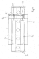
- the in the FIGS. 1 to 4 illustrated profiled rail guide comprises a guide carriage 1, which is mounted hydrostatically on a guide rail 2.
- the guide rail 2 has a head portion, which faces the carriage 1 and a foot portion, which faces a machine part not shown here, on which the guide rail 2 is fixed.
- the guide rail 2 along the longitudinal axis of the profiled rail guide is provided with a central surface 3.
- the guide rail 2 is provided with a plurality of arranged along the guide rail through holes 4, are provided by the fixing screws not shown here for attaching the guide rail to the machine part mentioned above. These passage openings 4 break through the middle surface 3 of the guide rail 2.
- the guide rail 1 is provided at its head portion with two upper bearing surfaces 5 and two lower bearing surfaces 6.
- the upper bearing surfaces 5 are flat; They are arranged inclined to the central surface 3, wherein the one upper bearing surface 5 is arranged on one side of the central surface 3 and the other upper bearing surface 5 to the other longitudinal side of the central surface 3.
- the lower bearing surfaces 6 are arranged below the upper bearing surfaces 5. These lower bearing surfaces 6 are inclined to both the central surface 3 and to the upper bearing surfaces 5.
- the guide carriage is provided with further upper and lower bearing surfaces 7, 8, wherein the upper and lower bearing surfaces 5, 6, 7, 8 of the guide carriage and the guide rail are associated with each other.
- FIG. 2 These storage areas are indicated.
- FIG. 2 It can also be seen that on the carriage 1 a total of four pressure pockets 9 are formed for the upper and lower bearing surfaces 5, 6, which can be acted upon with hydraulic fluid. Between the bearing surfaces 5, 6, 7, 8, a continuous lubricating film can be built up during operation of the hydrostatic profiled rail guide.
- FIG. 4 Two of these pressure pockets 9 are in the FIG. 4 shown schematically in a plan view of the inventive hydrostatic profile rail guide.
- the guide carriage 1 has a carrier body 10a and a headpiece 10 secured thereto on the front side.
- the head 10 is provided with a plurality of throttles 11, wherein these throttles 11 are formed in the present case as Kapillardrosseln. These throttles 11 are fully integrated into the header.
- a throttle 11 is provided for each pressure pocket 9, a throttle 11 is provided.
- the chokes 11 are connected in parallel. They open into a common hunt group 12, which is arranged on one side of the head piece 12.
- supply channels 13 are further integrated, which are connected on the one hand to all throttles 11 and the other to the common hunt group 12.
- an oil pump can be connected via a pressure hose to this collecting connection 12.
- FIG. 1 also shows that in FIG. 4 only schematically illustrated head piece 10 with the hunt group 12th
- FIG. 3 Finally, in a schematic illustration shows the circuit of the pressure pockets 9 and the throttles 11. With a dashed line L here the system limit of the guide carriage is indicated. This figure also shows an external pressure source 14 which is connected via a pressure hose 15 to the hunt group 12. Here is clearly the parallel circuit of the chokes 11 can be seen. Furthermore, the paths of the feed channels 13 can also be seen here, which are connected on the one hand to the central collecting port 12 and on the other hand to one of the throttles 11 on the other hand. The throttles 11 are finally connected to the pressure pockets 9; everyone Throttle 11 is associated with exactly one pressure pocket 9.
- FIG. 1 It can be seen that all chokes 11 are integrated within the clearance of the hydrostatic profiled rail guide.
- a hydrostatic profiled rail guide according to the invention can be easily exchanged for a profiled rail rolling guide according to DIN 645-1.
- DIN 645-1 the external dimensions of profile rail roller guides are defined.
- Hydrostatic profiled rail guides according to the invention can be provided with corresponding external dimensions.
Applications Claiming Priority (2)
| Application Number | Priority Date | Filing Date | Title |
|---|---|---|---|
| DE102005038341A DE102005038341A1 (de) | 2005-08-13 | 2005-08-13 | Hydrostatische Profilschienenführung |
| PCT/EP2006/007725 WO2007019972A2 (de) | 2005-08-13 | 2006-08-04 | Hydrostatische profilschienenführung |
Publications (2)
| Publication Number | Publication Date |
|---|---|
| EP1915543A2 EP1915543A2 (de) | 2008-04-30 |
| EP1915543B1 true EP1915543B1 (de) | 2014-03-26 |
Family
ID=37441344
Family Applications (1)
| Application Number | Title | Priority Date | Filing Date |
|---|---|---|---|
| EP06776601.4A Not-in-force EP1915543B1 (de) | 2005-08-13 | 2006-08-04 | Hydrostatische profilschienenführung |
Country Status (6)
| Country | Link |
|---|---|
| EP (1) | EP1915543B1 (zh) |
| JP (1) | JP4938014B2 (zh) |
| CN (1) | CN101253342B (zh) |
| DE (1) | DE102005038341A1 (zh) |
| ES (1) | ES2465649T3 (zh) |
| WO (1) | WO2007019972A2 (zh) |
Families Citing this family (13)
| Publication number | Priority date | Publication date | Assignee | Title |
|---|---|---|---|---|
| CN101590603B (zh) * | 2009-07-08 | 2011-01-05 | 路文忠 | 精密静压直线导轨 |
| CN101716725B (zh) * | 2009-12-31 | 2015-06-03 | 王清明 | 油膜静压导轨装置 |
| CN103410859B (zh) * | 2012-12-18 | 2017-07-14 | 芜湖陀曼精机科技有限公司 | 一种定压式静压导轨节流器 |
| CN103406767A (zh) * | 2012-12-18 | 2013-11-27 | 芜湖陀曼精机科技有限公司 | 滑块式静压导轨用泄油块与吸油液压回路组合装置 |
| CN103233979B (zh) * | 2013-05-08 | 2016-02-10 | 北京微纳精密机械有限公司 | 气体静压导轨组件 |
| CN104482046B (zh) * | 2014-11-26 | 2017-01-25 | 广东工业大学 | 易调易测高精度闭式恒压静压导轨节流器 |
| DE102015212285B3 (de) * | 2015-07-01 | 2016-10-27 | Schaeffler Technologies AG & Co. KG | Linearführungssystem und Verfahren zur Durchführung von Messungen an einem Linearführungssystem |
| CN105927665B (zh) * | 2016-06-24 | 2018-04-10 | 滁州欧博特电子制造有限公司 | 一种易于涂油的封闭型导轨 |
| CN106112573B (zh) * | 2016-08-23 | 2018-07-13 | 苏州陈那自动化技术有限公司 | 内置节流器的小型静压导轨 |
| CN107191479B (zh) * | 2017-05-22 | 2022-12-13 | 浙江长盛塑料轴承技术有限公司 | 直线运动导向机构 |
| CN109707732A (zh) * | 2019-03-11 | 2019-05-03 | 佛山艾克斯光电科技有限公司 | 一种超精密静压线轨系统 |
| CN112762093B (zh) * | 2019-11-04 | 2022-07-15 | 上银科技股份有限公司 | 节流器及使用其的液静压线性滑轨 |
| KR102267809B1 (ko) * | 2019-11-25 | 2021-06-22 | 하이윈 테크놀로지스 코포레이션 | 유량 제한기 및 이를 사용하는 정유압 리니어 가이드웨이 |
Family Cites Families (11)
| Publication number | Priority date | Publication date | Assignee | Title |
|---|---|---|---|---|
| DE2754395A1 (de) * | 1977-12-07 | 1979-06-13 | Bozina Dr Ing Perovic | Oelversorgungsanlage fuer hydrostatische fuehrungen und lager |
| US4506935A (en) * | 1982-04-12 | 1985-03-26 | Toyoda Koki Kabushiki Kaisha | Bar-type slide guiding apparatus with hydrostatic bearings |
| US4586830A (en) * | 1984-04-16 | 1986-05-06 | International Business Machines Corporation | Combination rotary gas bearing and seal apparatus |
| JPS6145110A (ja) * | 1984-08-06 | 1986-03-05 | Nippon Seiko Kk | スライダ−装置 |
| DD241387A1 (de) * | 1985-09-30 | 1986-12-10 | Werkzeugmasch Okt Veb | Hydrostatisches fuehrungssystem eines werkzeugschlittens an einer zahnradwaelzschleifmaschine |
| EP0304090B1 (en) * | 1987-08-20 | 1994-07-27 | Toyoda Koki Kabushiki Kaisha | Hydrostatically supporting device for slide |
| JPH0565920A (ja) * | 1991-09-05 | 1993-03-19 | Mitsutoyo Corp | 流体軸受装置 |
| JPH05240250A (ja) * | 1992-02-26 | 1993-09-17 | Teijin Seiki Co Ltd | 静圧流体軸受装置 |
| WO1999053207A1 (en) * | 1998-04-13 | 1999-10-21 | Thomson Industries, Inc. | Self-compensating hydrostatic bearing |
| US20040042689A1 (en) | 2002-08-30 | 2004-03-04 | Hardinge Inc. | Hydrostatic bearing for linear motion guidance |
| JP4335697B2 (ja) * | 2004-01-06 | 2009-09-30 | 株式会社岡本工作機械製作所 | 油静圧直動案内装置 |
-
2005
- 2005-08-13 DE DE102005038341A patent/DE102005038341A1/de not_active Withdrawn
-
2006
- 2006-08-04 WO PCT/EP2006/007725 patent/WO2007019972A2/de active Application Filing
- 2006-08-04 ES ES06776601.4T patent/ES2465649T3/es active Active
- 2006-08-04 CN CN2006800293167A patent/CN101253342B/zh not_active Expired - Fee Related
- 2006-08-04 JP JP2008526405A patent/JP4938014B2/ja not_active Expired - Fee Related
- 2006-08-04 EP EP06776601.4A patent/EP1915543B1/de not_active Not-in-force
Also Published As
| Publication number | Publication date |
|---|---|
| EP1915543A2 (de) | 2008-04-30 |
| WO2007019972A2 (de) | 2007-02-22 |
| CN101253342B (zh) | 2011-05-04 |
| WO2007019972A3 (de) | 2007-11-15 |
| JP2009505015A (ja) | 2009-02-05 |
| JP4938014B2 (ja) | 2012-05-23 |
| ES2465649T3 (es) | 2014-06-06 |
| CN101253342A (zh) | 2008-08-27 |
| DE102005038341A1 (de) | 2007-02-15 |
Similar Documents
| Publication | Publication Date | Title |
|---|---|---|
| EP1915543B1 (de) | Hydrostatische profilschienenführung | |
| DE2158179C2 (de) | Hydrostatisch druckausgeglichenes Stützlager für drehende Wellen | |
| DE102007058620B3 (de) | Kolbenschieberventil | |
| DE102011050021B4 (de) | Selbstkompensierendes hydrostatisches Gleitlager | |
| DE3247420C2 (zh) | ||
| EP1007861B1 (de) | Regler zur regelung eines fluidstroms einer hydrostatik- oder aerostatiksvorrichtung | |
| WO2015022120A1 (de) | Führung und führungselement | |
| WO2005075834A1 (de) | Messblendenanordnung für ein hydraulisches stromteil- und stromsummiergerät | |
| EP2090794B1 (de) | Lageranordnung | |
| DE2156696C2 (de) | Steuervorrichtung mit einer Meßspindel und einem Mitlaufteil | |
| DE2336512A1 (de) | Druckentlastungsventil | |
| DE102018111597A1 (de) | Hydrostatische Gleitführungsvorrichtung und Werkzeugmaschine mit der hydrostatischen Gleitführungsvorrichtung | |
| DE102008027517A1 (de) | Axialschubentlastung im Turbolader | |
| DE3528781C2 (zh) | ||
| EP2005272B1 (de) | Hydrostatische Profilschienenführung | |
| DE10325294A1 (de) | Hydraulische Steueranordnung | |
| DE2906670A1 (de) | Ventileinrichtung zur lastkompensierten steuerung eines hydraulischen verbrauchers | |
| DE3027819A1 (de) | Vorrichtung zur regelung einer verstellpumpe | |
| DE3229128A1 (de) | Lageranordnung | |
| EP1593864B1 (de) | Biegeausgleichswalze | |
| DE10062603B4 (de) | Aerostatisches Lager | |
| DE10211299B4 (de) | Ventilkombination | |
| DE102018001943A1 (de) | Durchflussmengenregler für hydrostatische Lagertaschen | |
| DE3918926C2 (zh) | ||
| WO2001042663A1 (de) | Hydraulische steueranordnung zum steuern von zwei unterschiedlich hohen drücken an einem hydraulischen verbraucher |
Legal Events
| Date | Code | Title | Description |
|---|---|---|---|
| PUAI | Public reference made under article 153(3) epc to a published international application that has entered the european phase |
Free format text: ORIGINAL CODE: 0009012 |
|
| AK | Designated contracting states |
Kind code of ref document: A2 Designated state(s): AT BE BG CH CY CZ DE DK EE ES FI FR GB GR HU IE IS IT LI LT LU LV MC NL PL PT RO SE SI SK TR |
|
| AX | Request for extension of the european patent |
Extension state: AL BA HR MK RS |
|
| 17P | Request for examination filed |
Effective date: 20080515 |
|
| RBV | Designated contracting states (corrected) |
Designated state(s): CH DE ES FR IT LI |
|
| RBV | Designated contracting states (corrected) |
Designated state(s): CH DE ES FR IT LI |
|
| 17Q | First examination report despatched |
Effective date: 20090710 |
|
| RAP1 | Party data changed (applicant data changed or rights of an application transferred) |
Owner name: SCHAEFFLER TECHNOLOGIES AG & CO. KG |
|
| DAX | Request for extension of the european patent (deleted) | ||
| GRAP | Despatch of communication of intention to grant a patent |
Free format text: ORIGINAL CODE: EPIDOSNIGR1 |
|
| INTG | Intention to grant announced |
Effective date: 20131030 |
|
| GRAS | Grant fee paid |
Free format text: ORIGINAL CODE: EPIDOSNIGR3 |
|
| GRAA | (expected) grant |
Free format text: ORIGINAL CODE: 0009210 |
|
| RAP1 | Party data changed (applicant data changed or rights of an application transferred) |
Owner name: SCHAEFFLER TECHNOLOGIES GMBH & CO. KG |
|
| AK | Designated contracting states |
Kind code of ref document: B1 Designated state(s): CH DE ES FR IT LI |
|
| REG | Reference to a national code |
Ref country code: CH Ref legal event code: EP |
|
| REG | Reference to a national code |
Ref country code: DE Ref legal event code: R096 Ref document number: 502006013628 Country of ref document: DE Effective date: 20140508 |
|
| REG | Reference to a national code |
Ref country code: ES Ref legal event code: FG2A Ref document number: 2465649 Country of ref document: ES Kind code of ref document: T3 Effective date: 20140606 |
|
| REG | Reference to a national code |
Ref country code: DE Ref legal event code: R097 Ref document number: 502006013628 Country of ref document: DE |
|
| PLBE | No opposition filed within time limit |
Free format text: ORIGINAL CODE: 0009261 |
|
| STAA | Information on the status of an ep patent application or granted ep patent |
Free format text: STATUS: NO OPPOSITION FILED WITHIN TIME LIMIT |
|
| 26N | No opposition filed |
Effective date: 20150106 |
|
| RAP2 | Party data changed (patent owner data changed or rights of a patent transferred) |
Owner name: SCHAEFFLER TECHNOLOGIES AG & CO. KG |
|
| REG | Reference to a national code |
Ref country code: CH Ref legal event code: PFA Owner name: SCHAEFFLER TECHNOLOGIES AG AND CO. KG, DE Free format text: FORMER OWNER: SCHAEFFLER TECHNOLOGIES GMBH AND CO. KG, DE |
|
| REG | Reference to a national code |
Ref country code: DE Ref legal event code: R081 Ref document number: 502006013628 Country of ref document: DE Owner name: SCHAEFFLER TECHNOLOGIES AG & CO. KG, DE Free format text: FORMER OWNER: SCHAEFFLER TECHNOLOGIES GMBH & CO. KG, 91074 HERZOGENAURACH, DE Effective date: 20150223 |
|
| REG | Reference to a national code |
Ref country code: DE Ref legal event code: R097 Ref document number: 502006013628 Country of ref document: DE Effective date: 20150106 |
|
| REG | Reference to a national code |
Ref country code: FR Ref legal event code: PLFP Year of fee payment: 10 |
|
| REG | Reference to a national code |
Ref country code: FR Ref legal event code: PLFP Year of fee payment: 11 |
|
| REG | Reference to a national code |
Ref country code: FR Ref legal event code: PLFP Year of fee payment: 12 |
|
| REG | Reference to a national code |
Ref country code: FR Ref legal event code: PLFP Year of fee payment: 13 |
|
| PGFP | Annual fee paid to national office [announced via postgrant information from national office to epo] |
Ref country code: FR Payment date: 20190828 Year of fee payment: 14 Ref country code: IT Payment date: 20190822 Year of fee payment: 14 |
|
| PGFP | Annual fee paid to national office [announced via postgrant information from national office to epo] |
Ref country code: CH Payment date: 20190827 Year of fee payment: 14 |
|
| PGFP | Annual fee paid to national office [announced via postgrant information from national office to epo] |
Ref country code: ES Payment date: 20191003 Year of fee payment: 14 |
|
| REG | Reference to a national code |
Ref country code: CH Ref legal event code: PL |
|
| PG25 | Lapsed in a contracting state [announced via postgrant information from national office to epo] |
Ref country code: CH Free format text: LAPSE BECAUSE OF NON-PAYMENT OF DUE FEES Effective date: 20200831 Ref country code: LI Free format text: LAPSE BECAUSE OF NON-PAYMENT OF DUE FEES Effective date: 20200831 |
|
| PG25 | Lapsed in a contracting state [announced via postgrant information from national office to epo] |
Ref country code: FR Free format text: LAPSE BECAUSE OF NON-PAYMENT OF DUE FEES Effective date: 20200831 Ref country code: IT Free format text: LAPSE BECAUSE OF NON-PAYMENT OF DUE FEES Effective date: 20200804 |
|
| REG | Reference to a national code |
Ref country code: ES Ref legal event code: FD2A Effective date: 20220110 |
|
| PGFP | Annual fee paid to national office [announced via postgrant information from national office to epo] |
Ref country code: DE Payment date: 20211020 Year of fee payment: 16 |
|
| PG25 | Lapsed in a contracting state [announced via postgrant information from national office to epo] |
Ref country code: ES Free format text: LAPSE BECAUSE OF NON-PAYMENT OF DUE FEES Effective date: 20200805 |
|
| REG | Reference to a national code |
Ref country code: DE Ref legal event code: R119 Ref document number: 502006013628 Country of ref document: DE |
|
| P01 | Opt-out of the competence of the unified patent court (upc) registered |
Effective date: 20230522 |
|
| PG25 | Lapsed in a contracting state [announced via postgrant information from national office to epo] |
Ref country code: DE Free format text: LAPSE BECAUSE OF NON-PAYMENT OF DUE FEES Effective date: 20230301 |