EP1915543B1 - Hydrostatische profilschienenführung - Google Patents
Hydrostatische profilschienenführung Download PDFInfo
- Publication number
- EP1915543B1 EP1915543B1 EP06776601.4A EP06776601A EP1915543B1 EP 1915543 B1 EP1915543 B1 EP 1915543B1 EP 06776601 A EP06776601 A EP 06776601A EP 1915543 B1 EP1915543 B1 EP 1915543B1
- Authority
- EP
- European Patent Office
- Prior art keywords
- guide
- throttles
- carriage
- profiled rail
- pressure
- Prior art date
- Legal status (The legal status is an assumption and is not a legal conclusion. Google has not performed a legal analysis and makes no representation as to the accuracy of the status listed.)
- Not-in-force
Links
Images


Classifications
-
- F—MECHANICAL ENGINEERING; LIGHTING; HEATING; WEAPONS; BLASTING
- F16—ENGINEERING ELEMENTS AND UNITS; GENERAL MEASURES FOR PRODUCING AND MAINTAINING EFFECTIVE FUNCTIONING OF MACHINES OR INSTALLATIONS; THERMAL INSULATION IN GENERAL
- F16C—SHAFTS; FLEXIBLE SHAFTS; ELEMENTS OR CRANKSHAFT MECHANISMS; ROTARY BODIES OTHER THAN GEARING ELEMENTS; BEARINGS
- F16C32/00—Bearings not otherwise provided for
- F16C32/06—Bearings not otherwise provided for with moving member supported by a fluid cushion formed, at least to a large extent, otherwise than by movement of the shaft, e.g. hydrostatic air-cushion bearings
- F16C32/0603—Bearings not otherwise provided for with moving member supported by a fluid cushion formed, at least to a large extent, otherwise than by movement of the shaft, e.g. hydrostatic air-cushion bearings supported by a gas cushion, e.g. an air cushion
- F16C32/0614—Bearings not otherwise provided for with moving member supported by a fluid cushion formed, at least to a large extent, otherwise than by movement of the shaft, e.g. hydrostatic air-cushion bearings supported by a gas cushion, e.g. an air cushion the gas being supplied under pressure, e.g. aerostatic bearings
- F16C32/0622—Bearings not otherwise provided for with moving member supported by a fluid cushion formed, at least to a large extent, otherwise than by movement of the shaft, e.g. hydrostatic air-cushion bearings supported by a gas cushion, e.g. an air cushion the gas being supplied under pressure, e.g. aerostatic bearings via nozzles, restrictors
-
- F—MECHANICAL ENGINEERING; LIGHTING; HEATING; WEAPONS; BLASTING
- F16—ENGINEERING ELEMENTS AND UNITS; GENERAL MEASURES FOR PRODUCING AND MAINTAINING EFFECTIVE FUNCTIONING OF MACHINES OR INSTALLATIONS; THERMAL INSULATION IN GENERAL
- F16C—SHAFTS; FLEXIBLE SHAFTS; ELEMENTS OR CRANKSHAFT MECHANISMS; ROTARY BODIES OTHER THAN GEARING ELEMENTS; BEARINGS
- F16C29/00—Bearings for parts moving only linearly
- F16C29/02—Sliding-contact bearings
- F16C29/025—Hydrostatic or aerostatic
Definitions
- the present invention relates to a hydrostatic profiled rail guide in which a guide carriage is mounted hydrostatically on a guide rail.
- a hydrostatic profiled rail guide has become known, wherein the guide carriage is provided on its side facing the guide rail with a plurality of pressure pockets for applying hydraulic fluid.
- lubricant is constantly pressed through inlet channels in the pressure pockets, in this way bearing surfaces of the carriage and the guide rail are always separated by a thin film of lubricant.
- hydrostatic bearings run frictionless. A stick-slip effect does not occur.
- Such hydrostatic profiled rail guides enable highly accurate position control in the sub-micrometer range.
- the carriage has two leg connected by a floor, which engage around the guide rail. Both on the ground and on the legs of the carriage carriage pressure pockets are formed. So that in all pressure pockets always a pressure is ensured, which provides a steady lubricating film between the bearing surfaces, throttles are turned on, which accomplish a reproducible dependence between the pocket pressure and the flow rate of the pressure medium.
- throttles are given by special storage bags on the carriage. However, this type of chokes require a very intensive production machining of the carriage.
- this object is achieved by the hydrostatic profiled rail guide of claim 1.
- the invention offers several advantages: Firstly, consuming machining on the carriage, since the built-in elements as chokes can be purchased parts, for example, in a recording of the carriage can be used. Furthermore, it is ensured with the hydrostatic profiled rail guide according to the invention that each pressure pocket can be controlled independently of the other pressure pockets.
- These chokes designed, for example, as built-in elements can be factory-set to a specific characteristic curve and finally installed in the guide carriage.
- Such chokes are formed by so-called capillary throttles or by membrane throttles.
- capillary throttles may optionally be preferred for the present invention, since capillary throttles are small in size and can be conveniently integrated into the carriage.
- Butterfly valves belong to the group of flow valves. These throttle valves, which are also suitable for this invention, can limit the volume flow as slot throttles. These slot throttles can also be provided with a check valve. They can also be designed as Einschraubventil so that they can be screwed, for example, in threaded bores of the carriage.
- a particularly small-sized hydrostatic profiled rail guide provides a guide carriage, in which an external pressure source can be connected to a common hunt group of the guide carriage, all chokes are connected to this common hunt group.
- the hydraulic fluid passes via the external pressure source through the hunt group to all chokes and from there finally with the set pressure into the respective pressure pocket of the hydrostatic profiled rail guide.
- both designed as a built-in element chokes, as well as the hunt group may be provided on a head piece of the carriage, which may be provided with supply channels, which are connected on the one hand to the hunt and the other on each of the throttles.
- These feed channels can be formed on such manufactured by injection molding headers in a favorable manner, for example by injection molding.
- cutting-edge production methods are conceivable, but they can be more expensive.
- a carriage which has a support body and a separately manufactured head piece, it may be appropriate depending on the application to provide a carriage, in which the head piece is integrally connected to the support body.
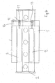
- the in the FIGS. 1 to 4 illustrated profiled rail guide comprises a guide carriage 1, which is mounted hydrostatically on a guide rail 2.
- the guide rail 2 has a head portion, which faces the carriage 1 and a foot portion, which faces a machine part not shown here, on which the guide rail 2 is fixed.
- the guide rail 2 along the longitudinal axis of the profiled rail guide is provided with a central surface 3.
- the guide rail 2 is provided with a plurality of arranged along the guide rail through holes 4, are provided by the fixing screws not shown here for attaching the guide rail to the machine part mentioned above. These passage openings 4 break through the middle surface 3 of the guide rail 2.
- the guide rail 1 is provided at its head portion with two upper bearing surfaces 5 and two lower bearing surfaces 6.
- the upper bearing surfaces 5 are flat; They are arranged inclined to the central surface 3, wherein the one upper bearing surface 5 is arranged on one side of the central surface 3 and the other upper bearing surface 5 to the other longitudinal side of the central surface 3.
- the lower bearing surfaces 6 are arranged below the upper bearing surfaces 5. These lower bearing surfaces 6 are inclined to both the central surface 3 and to the upper bearing surfaces 5.
- the guide carriage is provided with further upper and lower bearing surfaces 7, 8, wherein the upper and lower bearing surfaces 5, 6, 7, 8 of the guide carriage and the guide rail are associated with each other.
- FIG. 2 These storage areas are indicated.
- FIG. 2 It can also be seen that on the carriage 1 a total of four pressure pockets 9 are formed for the upper and lower bearing surfaces 5, 6, which can be acted upon with hydraulic fluid. Between the bearing surfaces 5, 6, 7, 8, a continuous lubricating film can be built up during operation of the hydrostatic profiled rail guide.
- FIG. 4 Two of these pressure pockets 9 are in the FIG. 4 shown schematically in a plan view of the inventive hydrostatic profile rail guide.
- the guide carriage 1 has a carrier body 10a and a headpiece 10 secured thereto on the front side.
- the head 10 is provided with a plurality of throttles 11, wherein these throttles 11 are formed in the present case as Kapillardrosseln. These throttles 11 are fully integrated into the header.
- a throttle 11 is provided for each pressure pocket 9, a throttle 11 is provided.
- the chokes 11 are connected in parallel. They open into a common hunt group 12, which is arranged on one side of the head piece 12.
- supply channels 13 are further integrated, which are connected on the one hand to all throttles 11 and the other to the common hunt group 12.
- an oil pump can be connected via a pressure hose to this collecting connection 12.
- FIG. 1 also shows that in FIG. 4 only schematically illustrated head piece 10 with the hunt group 12th
- FIG. 3 Finally, in a schematic illustration shows the circuit of the pressure pockets 9 and the throttles 11. With a dashed line L here the system limit of the guide carriage is indicated. This figure also shows an external pressure source 14 which is connected via a pressure hose 15 to the hunt group 12. Here is clearly the parallel circuit of the chokes 11 can be seen. Furthermore, the paths of the feed channels 13 can also be seen here, which are connected on the one hand to the central collecting port 12 and on the other hand to one of the throttles 11 on the other hand. The throttles 11 are finally connected to the pressure pockets 9; everyone Throttle 11 is associated with exactly one pressure pocket 9.
- FIG. 1 It can be seen that all chokes 11 are integrated within the clearance of the hydrostatic profiled rail guide.
- a hydrostatic profiled rail guide according to the invention can be easily exchanged for a profiled rail rolling guide according to DIN 645-1.
- DIN 645-1 the external dimensions of profile rail roller guides are defined.
- Hydrostatic profiled rail guides according to the invention can be provided with corresponding external dimensions.
Description
- Die vorliegende Erfindung betrifft eine hydrostatische Profilschienenführung, bei der ein Führungswagen auf einer Führungsschiene hydrostatisch gelagert ist.
- Aus
US 2004/0042689 A1 beispielsweise ist eine hydrostatische Profilschienenführung bekannt geworden, wobei der Führungswagen an seinen der Führungsschiene zugewandten Seiten mit mehreren Drucktaschen zur Beaufschlagung mit Hydraulikflüssigkeit versehen ist. Über eine externe Druckversorgung wird fortwährend Schmierstoff über Einlasskanäle in die Drucktaschen gepresst, wobei auf diese Weise Lagerflächen des Wagens und der Führungsschiene stets durch einen dünnen Schmierfilm voneinander getrennt sind. Dadurch tritt nur Flüssigkeitsreibung auf, die proportional zur Geschwindigkeit ist, mit der sich die Lagerflächen gegeneinander bewegen. Im Grenzfall laufen hydrostatische Lager reibungsfrei. Ein Stick-Slip-Effekt tritt nicht auf. Derartige hydrostatische Profilschienenführungen ermöglichen hochgenaue Positionsregelungen im Sub-Mikrometerbereich. - Der Führungswagen weist zwei durch einen Boden miteinander verbundene Schenkel auf, die die Führungsschiene umgreifen. Sowohl am Boden als auch an den Schenkeln des Führungswagens sind Drucktaschen ausgebildet. Damit in allen Drucktaschen stets ein Druck gewährleistet ist, der einen stetigen Schmierfilm zwischen den Lagerflächen bereitstellt, sind Drosseln eingeschaltet, die eine reproduzierbare Abhängigkeit zwischen dem Taschendruck und der Durchflussmenge des Druckmittels bewerkstelligen. Bei der
US 2004/0042689 A1 sind diese Vordrosseln durch besondere Lagertaschen am Führungswagen gegeben. Allerdings erfordern diese Art von Drosseln ein sehr intensive fertigungstechnische Bearbeitung des Führungswagens. - Es ist Aufgabe der vorliegenden Erfindung, eine alternative hydrostatische Profilschienenführung vorzuschlagen, bei der der Fertigungsaufwand des Führungswagens zur Bereitstellung der Drosseleinrichtung reduziert ist.
- Erfindungsgemäß wird diese Aufgabe durch die hydrostatische Profilschienenführung des Anspruchs 1 gelöst. Dadurch, dass für jede Drucktasche eine an dem Führungswagen als Einbauelement ausgebildete Drossel vorgesehen ist, bietet die Erfindung verschiedene Vorteile: Zum einen entfallen aufwendige Bearbeitungen am Führungswagen, da die als Einbauelemente ausgebildeten Drosseln zum Beispiel Zukaufteile sein können, die beispielsweise in eine Aufnahme des Führungswagens eingesetzt werden können. Des Weiteren ist mit der erfindungsgemäßen hydrostatischen Profilschienenführung sichergestellt, dass jede Drucktasche unabhängig von den anderen Drucktaschen angesteuert werden kann. Diese beispielsweise als Einbauelemente ausgebildeten Drosseln können ab Werk auf eine bestimmte Kennlinie eingestellt sein und schließlich in den Führungswagen eingebaut werden.
- Üblicherweise werden solche Drosseln durch so genannte Kapillardrosseln oder auch durch Membrandrosseln gebildet. Diese Kapillardrosseln können gegebenenfalls für die vorliegende Erfindung bevorzugt sein, da Kapillardrosseln kleinbauend sind und in günstiger Weise in den Führungswagen integriert werden können. Drosselventile gehören zur Gruppe der Stromventile. Diese auch für diese Erfindung geeigneten Drosselventile können als Schlitzdrosseln den Volumenstrom begrenzen. Diese Schlitzdrosseln können auch mit einem Rückschlagventil versehen sein. Sie können ferner als Einschraubventil ausgebildet sein, so dass sie beispielsweise in Gewindebohrungen des Führungswagens einschraubbar sind.
- Mit dieser erfindungsgemäßen hydrostatischen Profilschienenführung sind somit Anordnungen realisierbar, bei der alle Drosseln innerhalb des Lichtraumprofils des Führungswagens angeordnet sind. In anderen Worten ausgedrückt: Die Drosseln sind sämtlich innerhalb des Querschnittsumrisses des Führungswagens angeordnet.
- Eine besonders kleinbauende hydrostatische Profilschienenführung sieht einen Führungswagen vor, bei dem eine externe Druckquelle an einen gemeinsamen Sammelanschluss des Führungswagens angeschlossen werden kann, wobei alle Drosseln an diesen gemeinsamen Sammelanschluss angeschlossen sind. Die Hydraulikflüssigkeit gelangt über die externe Druckquelle durch den Sammelanschluss zu allen Drosseln und von dort schließlich mit dem eingestellten Druck in die jeweilige Drucktasche der hydrostatischen Profilschienenführung.
- In günstiger Weise können sowohl die als Einbauelement ausgebildeten Drosseln, als auch der Sammelanschluss an einem Kopfstück des Führungswagens vorgesehen sein, das mit Zuführkanälen versehen sein kann, die einerseits an den Sammelanschluss und die andererseits jeweils an eine der Drosseln angeschlossen sind. Diese Zuführkanäle können an derartigen im Spritzgussverfahren hergestellten Kopfstücken in günstiger Weise beispielsweise im Spritzverfahren geformt werden. Alternativ sind auch spangebende Herstellverfahren denkbar, die aber aufwendiger sein können. Anstelle eines Führungswagens, der einen Tragkörper und ein getrennt hergestelltes Kopfstück aufweist, mag es je nach Anwendung zweckmäßig sein, einen Führungswagen vorzusehen, bei dem das Kopfstück einstückig mit dem Tragkörper verbunden ist.
- Nachstehend wird die Erfindung anhand eines in insgesamt vier Figuren abgebildeten Ausführungsbeispieles erläutert. Es zeigen:
- Figur 1
- eine perspektivische Darstellung einer hydrostatischen Profilschienenführung,
- Figur 2
- die hydrostatische Profilschienenführung im Querschnitt, in schematischer Darstellung,
- Figur 3
- ein Funktionsschema der erfindungsgemäßen hydrostatischen Profilschienenführung und
- Figur 4
- eine Draufsicht auf die erfindungsgemäße hydrostatische Profilschienenführung.
- Die in den
Figuren 1 bis 4 abgebildete erfindungsgemäße Profilschienenführung umfasst einen Führungswagen 1, der auf einer Führungsschiene 2 hydrostatisch gelagert ist. Die Führungsschiene 2 hat einen Kopfabschnitt, der dem Führungswagen 1 zugewandt ist und einen Fußabschnitt, der einem hier nicht abgebildeten Maschinenteil zugewandt ist, auf dem die Führungsschiene 2 befestigt ist. An ihrem Kopfabschnitt ist die Führungsschiene 2 entlang der Längsachse der Profilschienenführung mit einer Mittelfläche 3 versehen. Die Führungsschiene 2 ist mit einer Vielzahl von entlang der Führungsschiene angeordneten Durchgangsöffnungen 4 versehen, durch die hier nicht abgebildete Befestigungsschrauben zum Befestigen der Führungsschiene an dem weiter oben erwähnten Maschinenteil vorgesehen sind. Diese Durchgangsöffnungen 4 durchbrechen die Mittelfläche 3 der Führungsschiene 2. - Die Führungsschiene 1 ist an ihrem Kopfabschnitt mit zwei oberen Lagerflächen 5 und zwei unteren Lagerflächen 6 versehen. Die oberen Lagerflächen 5 sind eben ausgebildet; Sie sind zu der Mittelfläche 3 geneigt angeordnet, wobei die eine obere Lagerfläche 5 zur einen Seite der Mittelfläche 3 und die andere obere Lagerfläche 5 zur anderen Längsseite der Mittelfläche 3 angeordnet ist. Die unteren Lagerflächen 6 sind unterhalb der oberen Lagerflächen 5 angeordnet. Diese unteren Lagerflächen 6 sind sowohl zu der Mittelfläche 3 als auch zu den oberen Lagerflächen 5 geneigt angeordnet.
- Der Führungswagen ist mit weiteren oberen und unteren Lagerflächen 7, 8 versehen, wobei die oberen und unteren Lagerflächen 5, 6, 7, 8 des Führungswagens und der Führungsschiene einander zugeordnet sind. In
Figur 2 sind diese Lagerflächen angedeutet. - Der
Figur 2 ist ferner zu entnehmen, dass an dem Führungswagen 1 insgesamt vier Drucktaschen 9 für die oberen und unteren Lagerflächen 5, 6 ausgebildet sind, die mit Hydraulikflüssigkeit beaufschlagt werden können. Zwischen den Lagerflächen 5, 6, 7, 8 kann im Betrieb der hydrostatischen Profilschienenführung ein stetiger Schmierfilm aufgebaut werden. - Zwei dieser Drucktaschen 9 sind in der
Figur 4 in einer Draufsicht auf die erfindungsgemäße hydrostatische Profilschienenführung schematisch abgebildet. Dieser schematischen Abbildung kann entnommen werden, dass der Führungswagen 1 einen Tragkörper 10a und ein daran stirnseitig befestigtes Kopfstück 10 aufweist. Das Kopfstück 10 ist mit mehreren Drosseln 11 versehen, wobei diese Drosseln 11 vorliegend als Kapillardrosseln ausgebildet sind. Diese Drosseln 11 sind in das Kopfstück vollständig integriert. Für jede Drucktasche 9 ist eine Drossel 11 vorgesehen. Die Drosseln 11 sind parallel geschaltet. Sie münden in einen gemeinsamen Sammelanschluss 12, der an einer Seite des Kopfstückes 12 angeordnet ist. In dieses Kopfstück 10 sind ferner Zuführkanäle 13 integriert, die einerseits an alle Drosseln 11 und die andererseits an den gemeinsamen Sammelanschluss 12 angeschlossen sind. An diesen Sammelanschluss 12 kann beispielsweise eine Ölpumpe über einen Druckschlauch angeschlossen werden. -
Figur 1 zeigt auch das inFigur 4 lediglich schematisch abgebildete Kopfstück 10 mit dem Sammelanschluss 12. -
Figur 3 schließlich zeigt in schematischer Abbildung die Schaltung der Drucktaschen 9 und der Drosseln 11. Mit einer gestrichelten Linie L ist hier die Systemgrenze des Führungswagens angedeutet. Diese Figur zeigt ferner eine externe Druckquelle 14 die über einen Druckschlauch 15 an den Sammelanschluss 12 angeschlossen ist. Hier ist deutlich die parallele Schaltung der Drosseln 11 zu erkennen. Ferner sind hier auch die Wege der Zuführkanäle 13 zu erkennen, die einerseits an den zentralen Sammelanschluss 12 und die andererseits jeweils an einen der Drosseln 11 angeschlossen sind. Die Drosseln 11 sind schließlich an die Drucktaschen 9 angeschlossen; Jeder Drossel 11 ist genau eine Drucktasche 9 zugeordnet. - Insbesondere der
Figur 1 ist zu entnehmen, dass alle Drosseln 11 innenhalb des Lichtraumprofils der hydrostatischen Profilschienenführung integriert sind. Das bedeutet, dass eine erfindungsgemäße hydrostatische Profilschienenführung problemlos gegen eine Profilschienenwälzführung gemäß DIN 645-1 ausgetauscht werden kann. In dieser zitierten DIN 645-1 sind die Außenmaße von Profilschienenwälzführungen definiert. Erfindungsgemäße hydrostatische Profilschienenführungen können mit entsprechenden Außenmaßen versehen sein. -
- 1
- Führungswagen
- 2
- Führungsschiene
- 3
- Mittelfläche
- 4
- Durchgangsöffnung
- 5
- obere Lagerfläche
- 6
- untere Lagerfläche
- 7
- obere Lagerfläche
- 8
- untere Lagerfläche
- 9
- Drucktasche
- 10
- Kopfstück
- 10a
- Tragkörper
- 11
- Drossel
- 12
- Sammelanschluss
- 13
- Zuführkanal
- 14
- Druckquelle
Claims (4)
- Hydrostatische Profilschienenführung, mit einem auf einer Führungsschiene (2) hydrostatisch gelagerten Führungswagen (1), der an der Führungsschiene (2) zugewandten Seiten mit mehreren Drucktaschen (9) zur Beaufschlagung mit Hydraulikflüssigkeit versehen ist, wobei Drosseln (11) zur Einstellung eines Volumenstroms in den Drucktaschen (9) vorgesehen sind, dadurch gekennzeichnet, dass für jede Drucktasche (9) jeweils eine an dem Führungswagen (1) als Einbauelement ausgebildete Drossel (11) vorgesehen ist, wobei der Führungswagen (1) einen an alle Drosseln (11) angeschlossenen gemeinsamen Sammelanschluß (12) für eine die Hydraulikflüssigkeit fördernde externe Druckquelle (14) aufweist, und wobei der Führungswagen (1) einen mit den Drucktaschen (9) versehenen Tragkörper (10a) und ein stirnseitig an dem Tragkörper (10a) angeordnetes Kopfstück (10) aufweist, in das die Drosseln (11) integriert sind.
- Hydrostatische Profilschienenführung nach Anspruch 1, bei der das Kopfstück (10) mit Zuführkanälen (13) versehen ist, die einerseits an den Sammelanschluß (12) und andererseits jeweils an eine der Drosseln (11) angeschlossen sind.
- Hydrostatische Profilschienenführung nach Anspruch 1, bei der die Drossel (11) durch eine Kapillardrossel oder durch eine Membrandrossel gebildet ist.
- Hydrostatische Profilschienenführung nach Anspruch 1, bei der die Drosseln (11) innerhalb des Querschnittsumrisses des Führungswagens (1) angeordnet sind.
Applications Claiming Priority (2)
| Application Number | Priority Date | Filing Date | Title |
|---|---|---|---|
| DE102005038341A DE102005038341A1 (de) | 2005-08-13 | 2005-08-13 | Hydrostatische Profilschienenführung |
| PCT/EP2006/007725 WO2007019972A2 (de) | 2005-08-13 | 2006-08-04 | Hydrostatische profilschienenführung |
Publications (2)
| Publication Number | Publication Date |
|---|---|
| EP1915543A2 EP1915543A2 (de) | 2008-04-30 |
| EP1915543B1 true EP1915543B1 (de) | 2014-03-26 |
Family
ID=37441344
Family Applications (1)
| Application Number | Title | Priority Date | Filing Date |
|---|---|---|---|
| EP06776601.4A Not-in-force EP1915543B1 (de) | 2005-08-13 | 2006-08-04 | Hydrostatische profilschienenführung |
Country Status (6)
| Country | Link |
|---|---|
| EP (1) | EP1915543B1 (de) |
| JP (1) | JP4938014B2 (de) |
| CN (1) | CN101253342B (de) |
| DE (1) | DE102005038341A1 (de) |
| ES (1) | ES2465649T3 (de) |
| WO (1) | WO2007019972A2 (de) |
Families Citing this family (13)
| Publication number | Priority date | Publication date | Assignee | Title |
|---|---|---|---|---|
| CN101590603B (zh) * | 2009-07-08 | 2011-01-05 | 路文忠 | 精密静压直线导轨 |
| CN101716725B (zh) * | 2009-12-31 | 2015-06-03 | 王清明 | 油膜静压导轨装置 |
| CN103406767A (zh) * | 2012-12-18 | 2013-11-27 | 芜湖陀曼精机科技有限公司 | 滑块式静压导轨用泄油块与吸油液压回路组合装置 |
| CN103410859B (zh) * | 2012-12-18 | 2017-07-14 | 芜湖陀曼精机科技有限公司 | 一种定压式静压导轨节流器 |
| CN103233979B (zh) * | 2013-05-08 | 2016-02-10 | 北京微纳精密机械有限公司 | 气体静压导轨组件 |
| CN104482046B (zh) * | 2014-11-26 | 2017-01-25 | 广东工业大学 | 易调易测高精度闭式恒压静压导轨节流器 |
| DE102015212285B3 (de) * | 2015-07-01 | 2016-10-27 | Schaeffler Technologies AG & Co. KG | Linearführungssystem und Verfahren zur Durchführung von Messungen an einem Linearführungssystem |
| CN105927665B (zh) * | 2016-06-24 | 2018-04-10 | 滁州欧博特电子制造有限公司 | 一种易于涂油的封闭型导轨 |
| CN106112573B (zh) * | 2016-08-23 | 2018-07-13 | 苏州陈那自动化技术有限公司 | 内置节流器的小型静压导轨 |
| CN107191479B (zh) * | 2017-05-22 | 2022-12-13 | 浙江长盛塑料轴承技术有限公司 | 直线运动导向机构 |
| CN109707732A (zh) * | 2019-03-11 | 2019-05-03 | 佛山艾克斯光电科技有限公司 | 一种超精密静压线轨系统 |
| CN112762093B (zh) * | 2019-11-04 | 2022-07-15 | 上银科技股份有限公司 | 节流器及使用其的液静压线性滑轨 |
| KR102267809B1 (ko) * | 2019-11-25 | 2021-06-22 | 하이윈 테크놀로지스 코포레이션 | 유량 제한기 및 이를 사용하는 정유압 리니어 가이드웨이 |
Family Cites Families (11)
| Publication number | Priority date | Publication date | Assignee | Title |
|---|---|---|---|---|
| DE2754395A1 (de) * | 1977-12-07 | 1979-06-13 | Bozina Dr Ing Perovic | Oelversorgungsanlage fuer hydrostatische fuehrungen und lager |
| US4506935A (en) * | 1982-04-12 | 1985-03-26 | Toyoda Koki Kabushiki Kaisha | Bar-type slide guiding apparatus with hydrostatic bearings |
| US4586830A (en) * | 1984-04-16 | 1986-05-06 | International Business Machines Corporation | Combination rotary gas bearing and seal apparatus |
| JPS6145110A (ja) * | 1984-08-06 | 1986-03-05 | Nippon Seiko Kk | スライダ−装置 |
| DD241387A1 (de) * | 1985-09-30 | 1986-12-10 | Werkzeugmasch Okt Veb | Hydrostatisches fuehrungssystem eines werkzeugschlittens an einer zahnradwaelzschleifmaschine |
| EP0304090B1 (de) * | 1987-08-20 | 1994-07-27 | Toyoda Koki Kabushiki Kaisha | Hydrostatische Lagerung für Gleitschiene |
| JPH0565920A (ja) * | 1991-09-05 | 1993-03-19 | Mitsutoyo Corp | 流体軸受装置 |
| JPH05240250A (ja) * | 1992-02-26 | 1993-09-17 | Teijin Seiki Co Ltd | 静圧流体軸受装置 |
| WO1999053207A1 (en) * | 1998-04-13 | 1999-10-21 | Thomson Industries, Inc. | Self-compensating hydrostatic bearing |
| US20040042689A1 (en) * | 2002-08-30 | 2004-03-04 | Hardinge Inc. | Hydrostatic bearing for linear motion guidance |
| JP4335697B2 (ja) * | 2004-01-06 | 2009-09-30 | 株式会社岡本工作機械製作所 | 油静圧直動案内装置 |
-
2005
- 2005-08-13 DE DE102005038341A patent/DE102005038341A1/de not_active Withdrawn
-
2006
- 2006-08-04 CN CN2006800293167A patent/CN101253342B/zh not_active Expired - Fee Related
- 2006-08-04 JP JP2008526405A patent/JP4938014B2/ja not_active Expired - Fee Related
- 2006-08-04 EP EP06776601.4A patent/EP1915543B1/de not_active Not-in-force
- 2006-08-04 WO PCT/EP2006/007725 patent/WO2007019972A2/de active Application Filing
- 2006-08-04 ES ES06776601.4T patent/ES2465649T3/es active Active
Also Published As
| Publication number | Publication date |
|---|---|
| WO2007019972A2 (de) | 2007-02-22 |
| JP4938014B2 (ja) | 2012-05-23 |
| CN101253342A (zh) | 2008-08-27 |
| ES2465649T3 (es) | 2014-06-06 |
| JP2009505015A (ja) | 2009-02-05 |
| CN101253342B (zh) | 2011-05-04 |
| WO2007019972A3 (de) | 2007-11-15 |
| EP1915543A2 (de) | 2008-04-30 |
| DE102005038341A1 (de) | 2007-02-15 |
Similar Documents
| Publication | Publication Date | Title |
|---|---|---|
| EP1915543B1 (de) | Hydrostatische profilschienenführung | |
| DE2158179C2 (de) | Hydrostatisch druckausgeglichenes Stützlager für drehende Wellen | |
| DE102007058620B3 (de) | Kolbenschieberventil | |
| DE102011050021B4 (de) | Selbstkompensierendes hydrostatisches Gleitlager | |
| DE3247420C2 (de) | ||
| EP1007861B1 (de) | Regler zur regelung eines fluidstroms einer hydrostatik- oder aerostatiksvorrichtung | |
| DE3625428A1 (de) | Proportional-drosselventil | |
| WO2015022120A1 (de) | Führung und führungselement | |
| WO2005075834A1 (de) | Messblendenanordnung für ein hydraulisches stromteil- und stromsummiergerät | |
| EP2090794B1 (de) | Lageranordnung | |
| DE2156696C2 (de) | Steuervorrichtung mit einer Meßspindel und einem Mitlaufteil | |
| DE102018111597A1 (de) | Hydrostatische Gleitführungsvorrichtung und Werkzeugmaschine mit der hydrostatischen Gleitführungsvorrichtung | |
| DE102008027517A1 (de) | Axialschubentlastung im Turbolader | |
| DE3528781C2 (de) | ||
| EP2005272B1 (de) | Hydrostatische Profilschienenführung | |
| DE3027819A1 (de) | Vorrichtung zur regelung einer verstellpumpe | |
| DE3229128A1 (de) | Lageranordnung | |
| EP1452744B1 (de) | Hydraulische Steueranordnung | |
| EP1593864B1 (de) | Biegeausgleichswalze | |
| EP2840374B1 (de) | Drosselblende für eine Sensoranordnung | |
| DE10062603B4 (de) | Aerostatisches Lager | |
| DE102014202411A1 (de) | Elektrisch angesteuertes Druckregelventil für eine verstellbare hydrostatische Pumpe und eine verstellbare hydrostatische Pumpe mit einem Druckregelventil | |
| DE10211299B4 (de) | Ventilkombination | |
| DE102018001943A1 (de) | Durchflussmengenregler für hydrostatische Lagertaschen | |
| DE102004057938B4 (de) | Vorrichtung zum aktiven Verstellen bewegbarer Elemente an einem rotierenden Maschinenteil |
Legal Events
| Date | Code | Title | Description |
|---|---|---|---|
| PUAI | Public reference made under article 153(3) epc to a published international application that has entered the european phase |
Free format text: ORIGINAL CODE: 0009012 |
|
| AK | Designated contracting states |
Kind code of ref document: A2 Designated state(s): AT BE BG CH CY CZ DE DK EE ES FI FR GB GR HU IE IS IT LI LT LU LV MC NL PL PT RO SE SI SK TR |
|
| AX | Request for extension of the european patent |
Extension state: AL BA HR MK RS |
|
| 17P | Request for examination filed |
Effective date: 20080515 |
|
| RBV | Designated contracting states (corrected) |
Designated state(s): CH DE ES FR IT LI |
|
| RBV | Designated contracting states (corrected) |
Designated state(s): CH DE ES FR IT LI |
|
| 17Q | First examination report despatched |
Effective date: 20090710 |
|
| RAP1 | Party data changed (applicant data changed or rights of an application transferred) |
Owner name: SCHAEFFLER TECHNOLOGIES AG & CO. KG |
|
| DAX | Request for extension of the european patent (deleted) | ||
| GRAP | Despatch of communication of intention to grant a patent |
Free format text: ORIGINAL CODE: EPIDOSNIGR1 |
|
| INTG | Intention to grant announced |
Effective date: 20131030 |
|
| GRAS | Grant fee paid |
Free format text: ORIGINAL CODE: EPIDOSNIGR3 |
|
| GRAA | (expected) grant |
Free format text: ORIGINAL CODE: 0009210 |
|
| RAP1 | Party data changed (applicant data changed or rights of an application transferred) |
Owner name: SCHAEFFLER TECHNOLOGIES GMBH & CO. KG |
|
| AK | Designated contracting states |
Kind code of ref document: B1 Designated state(s): CH DE ES FR IT LI |
|
| REG | Reference to a national code |
Ref country code: CH Ref legal event code: EP |
|
| REG | Reference to a national code |
Ref country code: DE Ref legal event code: R096 Ref document number: 502006013628 Country of ref document: DE Effective date: 20140508 |
|
| REG | Reference to a national code |
Ref country code: ES Ref legal event code: FG2A Ref document number: 2465649 Country of ref document: ES Kind code of ref document: T3 Effective date: 20140606 |
|
| REG | Reference to a national code |
Ref country code: DE Ref legal event code: R097 Ref document number: 502006013628 Country of ref document: DE |
|
| PLBE | No opposition filed within time limit |
Free format text: ORIGINAL CODE: 0009261 |
|
| STAA | Information on the status of an ep patent application or granted ep patent |
Free format text: STATUS: NO OPPOSITION FILED WITHIN TIME LIMIT |
|
| 26N | No opposition filed |
Effective date: 20150106 |
|
| RAP2 | Party data changed (patent owner data changed or rights of a patent transferred) |
Owner name: SCHAEFFLER TECHNOLOGIES AG & CO. KG |
|
| REG | Reference to a national code |
Ref country code: CH Ref legal event code: PFA Owner name: SCHAEFFLER TECHNOLOGIES AG AND CO. KG, DE Free format text: FORMER OWNER: SCHAEFFLER TECHNOLOGIES GMBH AND CO. KG, DE |
|
| REG | Reference to a national code |
Ref country code: DE Ref legal event code: R081 Ref document number: 502006013628 Country of ref document: DE Owner name: SCHAEFFLER TECHNOLOGIES AG & CO. KG, DE Free format text: FORMER OWNER: SCHAEFFLER TECHNOLOGIES GMBH & CO. KG, 91074 HERZOGENAURACH, DE Effective date: 20150223 |
|
| REG | Reference to a national code |
Ref country code: DE Ref legal event code: R097 Ref document number: 502006013628 Country of ref document: DE Effective date: 20150106 |
|
| REG | Reference to a national code |
Ref country code: FR Ref legal event code: PLFP Year of fee payment: 10 |
|
| REG | Reference to a national code |
Ref country code: FR Ref legal event code: PLFP Year of fee payment: 11 |
|
| REG | Reference to a national code |
Ref country code: FR Ref legal event code: PLFP Year of fee payment: 12 |
|
| REG | Reference to a national code |
Ref country code: FR Ref legal event code: PLFP Year of fee payment: 13 |
|
| PGFP | Annual fee paid to national office [announced via postgrant information from national office to epo] |
Ref country code: FR Payment date: 20190828 Year of fee payment: 14 Ref country code: IT Payment date: 20190822 Year of fee payment: 14 |
|
| PGFP | Annual fee paid to national office [announced via postgrant information from national office to epo] |
Ref country code: CH Payment date: 20190827 Year of fee payment: 14 |
|
| PGFP | Annual fee paid to national office [announced via postgrant information from national office to epo] |
Ref country code: ES Payment date: 20191003 Year of fee payment: 14 |
|
| REG | Reference to a national code |
Ref country code: CH Ref legal event code: PL |
|
| PG25 | Lapsed in a contracting state [announced via postgrant information from national office to epo] |
Ref country code: CH Free format text: LAPSE BECAUSE OF NON-PAYMENT OF DUE FEES Effective date: 20200831 Ref country code: LI Free format text: LAPSE BECAUSE OF NON-PAYMENT OF DUE FEES Effective date: 20200831 |
|
| PG25 | Lapsed in a contracting state [announced via postgrant information from national office to epo] |
Ref country code: FR Free format text: LAPSE BECAUSE OF NON-PAYMENT OF DUE FEES Effective date: 20200831 Ref country code: IT Free format text: LAPSE BECAUSE OF NON-PAYMENT OF DUE FEES Effective date: 20200804 |
|
| REG | Reference to a national code |
Ref country code: ES Ref legal event code: FD2A Effective date: 20220110 |
|
| PGFP | Annual fee paid to national office [announced via postgrant information from national office to epo] |
Ref country code: DE Payment date: 20211020 Year of fee payment: 16 |
|
| PG25 | Lapsed in a contracting state [announced via postgrant information from national office to epo] |
Ref country code: ES Free format text: LAPSE BECAUSE OF NON-PAYMENT OF DUE FEES Effective date: 20200805 |
|
| REG | Reference to a national code |
Ref country code: DE Ref legal event code: R119 Ref document number: 502006013628 Country of ref document: DE |
|
| P01 | Opt-out of the competence of the unified patent court (upc) registered |
Effective date: 20230522 |
|
| PG25 | Lapsed in a contracting state [announced via postgrant information from national office to epo] |
Ref country code: DE Free format text: LAPSE BECAUSE OF NON-PAYMENT OF DUE FEES Effective date: 20230301 |