EP1007861B1 - Regler zur regelung eines fluidstroms einer hydrostatik- oder aerostatiksvorrichtung - Google Patents
Regler zur regelung eines fluidstroms einer hydrostatik- oder aerostatiksvorrichtung Download PDFInfo
- Publication number
- EP1007861B1 EP1007861B1 EP98945208A EP98945208A EP1007861B1 EP 1007861 B1 EP1007861 B1 EP 1007861B1 EP 98945208 A EP98945208 A EP 98945208A EP 98945208 A EP98945208 A EP 98945208A EP 1007861 B1 EP1007861 B1 EP 1007861B1
- Authority
- EP
- European Patent Office
- Prior art keywords
- housing
- regulator
- flow resistance
- pressure chamber
- bearing
- Prior art date
- Legal status (The legal status is an assumption and is not a legal conclusion. Google has not performed a legal analysis and makes no representation as to the accuracy of the status listed.)
- Expired - Lifetime
Links
Images


Classifications
-
- F—MECHANICAL ENGINEERING; LIGHTING; HEATING; WEAPONS; BLASTING
- F16—ENGINEERING ELEMENTS AND UNITS; GENERAL MEASURES FOR PRODUCING AND MAINTAINING EFFECTIVE FUNCTIONING OF MACHINES OR INSTALLATIONS; THERMAL INSULATION IN GENERAL
- F16C—SHAFTS; FLEXIBLE SHAFTS; ELEMENTS OR CRANKSHAFT MECHANISMS; ROTARY BODIES OTHER THAN GEARING ELEMENTS; BEARINGS
- F16C32/00—Bearings not otherwise provided for
- F16C32/06—Bearings not otherwise provided for with moving member supported by a fluid cushion formed, at least to a large extent, otherwise than by movement of the shaft, e.g. hydrostatic air-cushion bearings
- F16C32/0629—Bearings not otherwise provided for with moving member supported by a fluid cushion formed, at least to a large extent, otherwise than by movement of the shaft, e.g. hydrostatic air-cushion bearings supported by a liquid cushion, e.g. oil cushion
- F16C32/064—Bearings not otherwise provided for with moving member supported by a fluid cushion formed, at least to a large extent, otherwise than by movement of the shaft, e.g. hydrostatic air-cushion bearings supported by a liquid cushion, e.g. oil cushion the liquid being supplied under pressure
- F16C32/0644—Details of devices to control the supply of liquids to the bearings
- F16C32/0648—Details of devices to control the supply of liquids to the bearings by sensors or pressure-responsive control devices in or near the bearings
-
- F—MECHANICAL ENGINEERING; LIGHTING; HEATING; WEAPONS; BLASTING
- F16—ENGINEERING ELEMENTS AND UNITS; GENERAL MEASURES FOR PRODUCING AND MAINTAINING EFFECTIVE FUNCTIONING OF MACHINES OR INSTALLATIONS; THERMAL INSULATION IN GENERAL
- F16C—SHAFTS; FLEXIBLE SHAFTS; ELEMENTS OR CRANKSHAFT MECHANISMS; ROTARY BODIES OTHER THAN GEARING ELEMENTS; BEARINGS
- F16C29/00—Bearings for parts moving only linearly
- F16C29/02—Sliding-contact bearings
- F16C29/025—Hydrostatic or aerostatic
-
- G—PHYSICS
- G05—CONTROLLING; REGULATING
- G05D—SYSTEMS FOR CONTROLLING OR REGULATING NON-ELECTRIC VARIABLES
- G05D7/00—Control of flow
- G05D7/01—Control of flow without auxiliary power
- G05D7/0106—Control of flow without auxiliary power the sensing element being a flexible member, e.g. bellows, diaphragm, capsule
- G05D7/0113—Control of flow without auxiliary power the sensing element being a flexible member, e.g. bellows, diaphragm, capsule the sensing element acting as a valve
-
- Y—GENERAL TAGGING OF NEW TECHNOLOGICAL DEVELOPMENTS; GENERAL TAGGING OF CROSS-SECTIONAL TECHNOLOGIES SPANNING OVER SEVERAL SECTIONS OF THE IPC; TECHNICAL SUBJECTS COVERED BY FORMER USPC CROSS-REFERENCE ART COLLECTIONS [XRACs] AND DIGESTS
- Y10—TECHNICAL SUBJECTS COVERED BY FORMER USPC
- Y10T—TECHNICAL SUBJECTS COVERED BY FORMER US CLASSIFICATION
- Y10T137/00—Fluid handling
- Y10T137/7722—Line condition change responsive valves
- Y10T137/7781—With separate connected fluid reactor surface
- Y10T137/7784—Responsive to change in rate of fluid flow
- Y10T137/7787—Expansible chamber subject to differential pressures
- Y10T137/7788—Pressures across fixed choke
-
- Y—GENERAL TAGGING OF NEW TECHNOLOGICAL DEVELOPMENTS; GENERAL TAGGING OF CROSS-SECTIONAL TECHNOLOGIES SPANNING OVER SEVERAL SECTIONS OF THE IPC; TECHNICAL SUBJECTS COVERED BY FORMER USPC CROSS-REFERENCE ART COLLECTIONS [XRACs] AND DIGESTS
- Y10—TECHNICAL SUBJECTS COVERED BY FORMER USPC
- Y10T—TECHNICAL SUBJECTS COVERED BY FORMER US CLASSIFICATION
- Y10T137/00—Fluid handling
- Y10T137/7722—Line condition change responsive valves
- Y10T137/7781—With separate connected fluid reactor surface
- Y10T137/7784—Responsive to change in rate of fluid flow
- Y10T137/7787—Expansible chamber subject to differential pressures
- Y10T137/7791—Pressures across flow line valve
Definitions
- the invention relates to a controller for regulation at least one hydrostatic or aerostatic bag one bearing, lead screw nut or guiding the supplied media flow according to the generic term of claim 1.
- Regulators of the type mentioned here are known for liquids (DE 35 33 037 C1). They are characterized by the fact that the fluid flow influenced by the controller increases as the pressure in the hydrostatic pocket increases. Hydrostatic bearings, lead screw nuts or guides, which interact with controllers of the type mentioned above, are characterized by the fact that the achievable stiffness and loads of these elements with comparable technical data are significantly greater than those with alternative systems.
- the flow rate Q is proportional to the third power of the gap height or the height h of the gap of the pocket through which the medium flows. With laminar flow, the condition Q / p ⁇ h 3 / ⁇ results, with ⁇ denoting the dynamic viscosity of the medium or the liquid. This relationship applies in a similar way to gaseous media.
- the known controller is designed so that usually at least two controllers combined in one block are and from a common pressure connection be fed. This concept leads to many cases that between the controllers and the hydrostatic bags with sometimes considerable Comparatively long connecting lines created must be, the spatial accommodation these lines are often very difficult is, for example, in the supply of screw drives with hydrostatic nut.
- a disadvantage of the known controller is that this often due to the high kinetic energy of the fluid / gas in the lines for oscillation inclines.
- a controller is proposed of the features mentioned in claim 1 having.
- the controller is characterized in that the counter surface of the bearing, lead screw nut or is assigned to the guide and that the controller housing a a passage for the media flow has extensive investment area with which Controller housing in the assembled state on the storage, Threaded nut or the guide assigned Mating surface so that a direct Media connection between controller and bag and if necessary between controller and media supply is created.
- In connection with the present Invention is under "direct" media connection understood a connection without screwing and additional mounting elements becomes.
- the controller to the counter surface becomes the media connection at the same time educated. On the one hand, this allows the structure of the controller and on the other hand the effort be reduced for its assembly.
- the counter surface For example, a partial area of a Bearing housing, lead screw nut or be the leader.
- the controller is simple and quick to assemble and still stands out by a simple structure.
- the controller housing at least comprises two housing parts, between which the first pressure chamber, the control element, the second Pressure chamber and the second flow resistance arranged are. This makes it particularly compact Construction of the controller can be realized.
- An embodiment of the controller is also preferred, where the first flow resistance into the contact surface formed on the first housing part and / or is worked into the counter surface.
- “Incorporation” is both the introduction of the first flow resistance by means of a Cutting tool, for example a milling cutter, understood, as well as a non-cutting processing.
- the first flow resistance can be used for this provided surface also pressed / pressed or in the manufacture of the first housing part and / or the counter surface are molded.
- Figure 1 shows a cross section of a first embodiment a controller 1, which is used regulate a media flow that a consumer, especially one not shown here hydrostatic or an aerostatic bag is supplied via a media connection 3.
- a controller 1 is one driven by a motor, not shown Pump that serves as a media supply and a Provides media stream via a feed line 5, for example with a liquid medium, preferably Oil, supplies.
- a liquid medium preferably Oil
- the regulator 1 has a regulator housing 7 which comprises two separable housing parts 9 and 11.
- the first housing part designed as a circular disc 9 is in a blind bore 13 of the cup-shaped second housing part 11 arranged.
- the blind bore 13 has one on the Adapted outer contour of the first housing part 9 Contour on and is accordingly circular.
- the first housing part 9 lies with his the surface 15 facing the bottom 15 of the blind bore 13 17 on this, the thickness of the first Housing part 9 is chosen such that the Surface 17 opposite side of the first Housing part 19, namely the contact surface 19, in essentially in the same perpendicular to the image plane of the imaginary plane E1 lies like the housing surface 21 of the second housing part 11th
- the regulator 1 is in the assembled state in FIG shown.
- controller 1 This comprises three pressure rooms, which by one formed by a resilient plate Control 25 are separated.
- the first printing room 27 is an open edge 29 in the first housing part 9, which extends up to a passage opening 30 extends at the location of the first Housing part 9 is arranged, which in the assembled State of controller 1 in the counter surface 23 opposite supply line 5 is opposite, connected to the supply line 5.
- the first Pressure chamber 27 becomes p1 with a first pressure level charged that essentially that of the media supply equivalent.
- the second pressure chamber 31 is via an unchangeable first flow resistance 33 with the supply line 5 and so with the media supply, i.e. the one not shown Pump connected. In the second pressure chamber 31 lies with a flow of the medium through the first Flow resistance 33 a second pressure level p2 before.
- the third pressure room will follow discussed in more detail.
- the first flow resistance 33 is at this Embodiment in the contact surface 19 of the first Housing part 9 incorporated and is by two circular ring grooves 35a and 35b are formed, the one formed in the form of an elongated hole Groove 37 are interconnected.
- the groove 37 is -like the annular grooves 35a, 35b- starting from the contact surface 19 of the first housing part 9 in this brought in. That in connection with the media supply standing supply line 5 opens into the outer Annular groove 35 a in an area that is to the groove 37 offset by an angular range of approximately 180 ° is.
- This from a peripheral region of the annular groove 35a formed area in which the medium from the Feed line 5 flows into the controller, is as follows referred to as passage opening 30.
- FIG. 2 which is a bottom view of the controller 1 according Figure 1 shows, evidently, that flows from the media supply delivered medium in two with Arrows 39 indicated partial streams, one of which clockwise and the other counterclockwise over an angular range the ring groove 35a from approximately 180 ° to the groove 37. From there the medium reaches the inner Ring groove 35b and in turn divides into two partial streams on that clockwise and counterclockwise over an angular range of the circular ring groove 35b from approximately 180 ° to a - in this embodiment formed as a circular bore 41 Channel and from this to the second Flow pressure chamber 31.
- the control element 25 shown in FIG. 1 is in one of the surface 17 of the first housing part 9 outgoing, here circularly trained Well 43 introduced such that the well 43 in the first pressure chamber 27 and the second Pressure chamber 31 is divided. This is the control 25 at least largely pressure-tight in the Well 43 arranged.
- the medium When the pump is operating, the medium is supplied via the supply line 5 and over the first flow resistance 33 conveyed into the second pressure chamber 31. From there, the medium passes through the variable second flow resistance 49, namely via a passage gap influenced by the control element 25 between the contact surface of the control element 25 and the annular surface 47, in the central bore 45. From this, the medium passes through a passage opening 46 in the arranged in the housing 24 Connection line 26 and on to the pocket.
- the first flow resistance 33 causes in operation the regulator 1 a pressure drop, so that the second pressure chamber 31 given second pressure level is smaller than the first pressure level p1 in the first Printing room 27.
- the variable second one Flow resistance 49 a pressure drop during operation, so that in the media connection 3 (Hole 45, connecting line 26) given Pressure level p3, which is the pressure in the hydrostatic pocket corresponds to, smaller than the pressure level p2 is.
- Figure 1 shows that the control element 25 on the one hand with the pressure p1 in the first pressure chamber 27 and on the other hand with that in the second pressure chamber 31 given pressure p2 and that in the third pressure chamber or given in the media connection 3 Pressure p3 is applied. It also works the spring force of a resilient Plate formed control 25 such that this with that based on the pressure level p2 and p3 Compressive force is rectified.
- controller 1 In steady-state operation of controller 1, that is constant pump pressure p1 and constant pressure p3 is the sum of the forces from the three mentioned Press and the spring force on the control 25 equals zero. If the pressure p2 is constant Pressure p1 and p3 due to a fault for example reduced, the control element 25 would then the predominant pressure p1 in Figure 1 moved right and the size of the variable second Flow resistance 49 increased so that the Sum of the forces on the control element 25 again is zero, so that the pressure p2 is its reached its original value again. At a would increase p2 due to a disturbance the reverse process take place. By the controller 1 becomes a at constant pressure p1 and p3 constant differential pressure (p1 - p2) over the first Flow resistance 33 and thus through the Controller 1 set.
- FIG. 3 shows a top view of the controller 1, whose second housing part 11 several, here in total has four bores 51 which are both extend through the cover of the second housing part 11, as well as through its coat.
- fasteners not shown, for example screws through the Bores 51 inserted through and in designated Threaded holes in the housing 24 of the storage, Threaded nut or guide introduced are screwed in.
- the case surface 21 of the second housing part 11 and the Contact surface 19 of the in the blind bore 13 of the second housing part 11 arranged first housing part 9 with the counter surface 23 of the bearing, threaded nut or guided tour. This means that no additional assembly elements are required a direct media connection between Controller 1 and pocket and between controller 1 and Media supply created.
- the blind bore 13 of the second housing part 11 is compared to the environment by means of a in FIG seal 53 shown sealed in a Ring groove 55 is arranged.
- the annular groove 55 is starting from the housing surface 21 of the second housing part 11 introduced into this. Still is the passage opening 46 of the bore 45 in the contact area of the contact surface 19 on the counter surface 21 with respect to the annular groove 35b of the first flow resistance 33 sealed by means of a seal 57, the - starting from the contact surface 19 of the first housing part 9- in a surrounding the bore 45 Annular groove 59 is arranged.
- the first flow resistance 33 can be in the contact surface 19 and / or incorporated into the counter surface 23 become. But it is also possible the first Flow resistance 33 in the housing surface 21 of the second housing part 11 to integrate. A further possibility of arranging the first Flow resistance 33 is in the surface 17th of the first housing part 9, that is, that of the contact surface 19 facing away from the first housing part 9. It should be noted that the first flow resistance 33 in the first housing part 9, the second housing part 11 and / or the housing 24 of the Storage, threaded nut or guide can be integrated is.
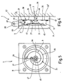
- FIGS. 1 to 3 shows a cross section of a second embodiment of the controller 1. Parts that with which correspond in FIGS. 1 to 3 provided with the same reference numerals so that the description of which refers to FIGS. 1 to 3 becomes.
- the Counter surface 23 'on which the first housing part 9 with its contact surface 19 and the second housing part 11 rest with its housing surface 21, of a surface one between the controller 1 and the housing 24 of the storage, threaded nut or guide arranged intermediate plate 61 is formed.
- Threading channel 62 introduced the hole 45 in the first housing part 9 of the controller 1 of the bearing 24 in the housing, threaded nut or guide arranged connecting line 26 connects that up to the hydro or aerostat pocket extends.
- the first, here formed by only one annular groove 35 Flow resistance 33 is also in the in Figure 4 illustrated embodiment in the Contact surface 19 of the first housing part 9 incorporated.
- the first flow resistance of the regulator to be worked into the intermediate plate 61 only, for example in the surface of the intermediate plate 61 attached to the housing 24 of the bearing, Threaded nut or guide is present. It is also possible to use the first flow resistance partially or fully into the housing 24 to integrate. It should be noted that the first flow resistance in the first housing part 9, the intermediate plate 61 and / or the housing 24 can be integrated.
- FIG. 5 shows a bottom view of the one in FIG. 4 shown controller 1, in which the first flow resistance of only one, here spiral Ring groove 35 is formed. This is outgoing from the contact surface 19 of the first housing part 9 introduced into this.
- FIG. 6 shows a cross section of a third embodiment of the controller 1. Same parts are provided with the same reference numerals, so that for their description to the previous figures is referred. In the following only the differences are discussed in more detail.
- the first housing part 9 of the controller 1 is in one circular blind hole 69 arranged in a only housing 24 indicated by dashed lines storage, lead screw nut or guide is introduced.
- the first housing part 9 lies with its contact surface 19 on the counter surface 23 of the Housing 24 at the bottom of the blind hole 69 is formed.
- controller 1 is disk-shaped formed and on the housing 24 of the Bearing, lead screw nut or guidance such attached that the blind bore 69 with the therein arranged first housing part 9 closed is.
- This embodiment of the controller 1 with the partially in the housing 24 of the bearing, threaded nut or guide integrated controller housing 7 is particularly space-saving.
- controller housing 7 comprises at least two housing parts, between which the first pressure chamber 27, the control element 25, the second pressure chamber 31 and the second Flow resistance 49 are arranged.
- the first flow resistance 33 is in the embodiment 6 in the first Housing part 9 of the controller housing 7 trained Contact surface 19 incorporated. It is also possible the first flow resistance 33 in the Incorporate counter surface 23 or 23 ', the counter surface 23 'a housing surface of the Bearing, lead screw nut or guide, or the surface one between the controller and the Bearing, threaded nut or guide arranged Intermediate plate 61 is. Another Embodiment is provided that the first Flow resistance 33 both in the contact surface 19 of the first housing part 9 of the controller housing 7, and also worked into the counter surface 23, 23 ' is. The first flow resistance 33 can be without further also in the housing surface 21 of the second housing part 11 or 11 'are introduced. Finally, it is also possible that the first Flow resistance 33 into the surface 17 of the first housing part 9 is integrated.
- the first flow resistance 33 can be one or more grooves are formed, which are linear and / or have a curved course, for example spiral or circular.
- the Groove or the grooves that the first Flow resistance can be practically any have any shape.
- the first flow resistance when disassembled of the controller can be cleaned very easily. This is also in one embodiment possible at which the first flow resistance into the housing surface 21 of the second housing part 11 or 11 'is introduced.
- the controller 1 can be replaced, for example, by that the controller housing at least two housing parts includes, very easily possible by at least one of the two housing parts by one other is exchanged, for example the first flow resistance and thus the control behavior of the controller can be changed.
- controller 1 direct media connection between controller and bag and / or media supply when mounting of controller 1 to one of the bearings, threaded nut or the counter surface assigned to the guide is formed immediately is an assembly of the controller can be carried out easily and quickly without that additional mounting elements are required. Furthermore, by the immediate arrangement of the controller on the hydro / aerostat pocket of the storage, Lead nut or guide short Connection lines between the controller and the Pocket can be realized so that the medium in the Connection lines not at all or only relatively vibrates slightly.
Description
- Figuren 1 bis 3
- eine Draufsicht, einen Querschnitt und eine Untersicht eines Ausführungsbeispiels des erfindungsgemäßen Reglers;
- Figuren 4 und 5
- eine Untersicht und einen Querschnitt eines weiteren Ausführungsbeispiels des Reglers und
- Figur 6
- Querschnitt eines dritten Ausführungsbeispiels des Reglers.
Claims (10)
- Regler (1) zur Regelung eines mindestens einer Hydrostatik- oder Aerostatiktasche einer Lagerung, Gewindespindelmutter oder einer Führung von einer Medienversorgung (5) zugeführten Medienstromes, mit einem Reglergehäuse (7), mit einer Gegenfläche (23;23') und mit von einem gegen die Kraft eines Federelements beweglichen Steuerelement (25) getrennten Druckräumen (27,31,45), von denen ein mit einem ersten Druckniveau (p1) beaufschlagter erster Druckraum (27) unmittelbar mit der Medienversorgung (5), ein mit einem niedrigeren zweiten Druckniveau (p2) beaufschlagter zweiter Druckraum (31) über einen ersten Strömungswiderstand (33) mit der Medienversorgung und ein dritter Druckraum(45), der mit einem dritten Druckniveau (p3) beaufschlagt ist, das dem in der Hydrostatik- oder Aerostatiktasche entspricht, mit der Hydrostatik- oder Aerostatiktasche verbunden ist, wobei durch das Steuerelement (25) ein zwischen dem zweiten und dritten Druckraum angeordneter, den der Tasche zugeführten Medienstrom beeinflussender, variabler zweiter Strömungswiderstand (49), dessen Größe durch die Kraftwirkung des ersten Druckraumes (27) angehoben, durch die Wirkung der Federkraft sowie die Kraftwirkungen des zweiten und dritten Druckraumes aber vermindert wird, ausgebildet ist, dadurch gekennzeichnet, daß die Gegenfläche (23;23') der Lagerung, Gewindespindelmutter oder der Führung zugeordnet ist und daß das Reglergehäuse (7) eine eine Durchlaßöffnung (30;46) für den Medienstrom umfassende Anlagefläche (19) aufweist, mit der das Reglergehäuse (7) im montierten Zustand an der der Lagerung, Gewindespindelmutter oder der Führung zugeordneten Gegenfläche (23;23') anliegt, so daß eine direkte Medienverbindung (3;3') zwischen Regler (1) und Tasche und gegebenenfalls zwischen Regler (1) und Medienversorgung geschaffen wird.
- Regler nach Anspruch 1, dadurch gekennzeichnet, daß das Reglergehäuse (7) mindestens drei Gehäuseteile (9,11,24;11,9,61;11',9,24) umfaßt, zwischen denen der erste Druckraum (27), das Steuerelement (25), der zweite Druckraum (31) und der zweite Strömungswiderstand (49) angeordnet sind.
- Regler nach Anspruch 1 oder 2, dadurch gekennzeichnet, daß der erste Strömungswiderstand (33) in die am ersten Gehäuseteil (9) ausgebildete Anlagefläche (19) und/oder in die Gegenfläche (23;23') eingearbeitet ist.
- Regler nach einem der vorhergehenden Ansprüche, dadurch gekennzeichnet, daß die Gegenfläche (23;23') eine Gehäusefläche der Lagerung, Gewindespindelmutter oder Führung, oder die Oberfläche einer zwischen dem Regler und der Lagerung, Gewindespindelmutter oder Führung angeordneten Zwischenplatte (61) ist.
- Regler nach einem der vorhergehenden Ansprüche 1, 2 oder 4, dadurch gekennzeichnet, daß der erste Strömungswiderstand in eine Gehäusefläche (21) des zweiten Gehäuseteils eingebracht ist.
- Regler nach einem der vorhergehenden Ansprüche 1, 2 oder 4, dadurch gekennzeichnet, daß der erste Strömungswiderstand in die der Anlagenfläche (19) abgewandte Oberfläche (17) des die Anlagefläche (19) aufweisenden ersten Gehäuseteils (9) eingebracht ist.
- Regler nach einem der vorhergehenden Ansprüche, dadurch gekennzeichnet, daß der erste Strömungswiderstand (33) über mindestens einen, in das erste Gehäuseteil (9) eingebrachten -vorzugsweise als kreisrunde Bohrung (41) ausgebildeten- Kanal mit dem zweiten Druckraum (31) verbunden ist.
- Regler nach einem der vorhergehenden Ansprüche, dadurch gekennzeichnet, daß die Medienverbindung (3') zwischen Medienversorgung und Regler (1) über das zweite Gehäuseteil (11) realisierbar ist.
- Regler nach einem der vorhergehenden Ansprüche, dadurch gekennzeichnet, daß das zweite -vorzugsweise topfförmig ausgebildete- Gehäuseteil (11) eine vorzugsweise kreisförmige Sackbohrung (13) aufweist, in der das erste -vorzugsweise runde- Gehäuseteil (9) angeordnet ist.
- Regler nach einem der vorhergehenden Ansprüche 1 bis 8, dadurch gekennzeichnet, daß das erste -vorzugsweise runde- Gehäuseteil (9) in einer in das Gehäuse (24) der Lagerung, Gewindespindelmutter oder Führung eingebrachten -vorzugsweise kreisrunden- Sackbohrung (69) angeordnet ist und daß die Sackbohrung (69) mittels des zweiten Gehäuseteils (11') verschließbar ist.
Applications Claiming Priority (3)
| Application Number | Priority Date | Filing Date | Title |
|---|---|---|---|
| DE19737781A DE19737781A1 (de) | 1997-08-29 | 1997-08-29 | Regler zur Regelung eines mindestens einer Hydrostatik- oder Aerostatiktasche einer Lagerung, Gewindespindelmutter, oder einer Führung zugeführten Medienstromes |
| DE19737781 | 1997-08-29 | ||
| PCT/EP1998/005080 WO1999011943A1 (de) | 1997-08-29 | 1998-08-11 | Regler zur regelung des fluidstromes einer hydrostatik- oder aerostatikvorrichtung |
Publications (2)
| Publication Number | Publication Date |
|---|---|
| EP1007861A1 EP1007861A1 (de) | 2000-06-14 |
| EP1007861B1 true EP1007861B1 (de) | 2002-09-04 |
Family
ID=7840621
Family Applications (1)
| Application Number | Title | Priority Date | Filing Date |
|---|---|---|---|
| EP98945208A Expired - Lifetime EP1007861B1 (de) | 1997-08-29 | 1998-08-11 | Regler zur regelung eines fluidstroms einer hydrostatik- oder aerostatiksvorrichtung |
Country Status (7)
| Country | Link |
|---|---|
| US (1) | US6276491B1 (de) |
| EP (1) | EP1007861B1 (de) |
| JP (1) | JP3660870B2 (de) |
| AT (1) | ATE223563T1 (de) |
| DE (2) | DE19737781A1 (de) |
| ES (1) | ES2181268T3 (de) |
| WO (1) | WO1999011943A1 (de) |
Cited By (1)
| Publication number | Priority date | Publication date | Assignee | Title |
|---|---|---|---|---|
| US8770841B2 (en) | 2012-08-21 | 2014-07-08 | Industrial Technology Research Institute | Hydrostatic plate bearing |
Families Citing this family (14)
| Publication number | Priority date | Publication date | Assignee | Title |
|---|---|---|---|---|
| JP4335697B2 (ja) * | 2004-01-06 | 2009-09-30 | 株式会社岡本工作機械製作所 | 油静圧直動案内装置 |
| EP2359886A1 (de) * | 2010-02-12 | 2011-08-24 | Debiotech S.A. | Mikromechanischer passiver Durchflussregler |
| GB2484924A (en) | 2010-10-25 | 2012-05-02 | Amirim Products Dev & Patents Ltd | An on line drip irrigation emitter having an inlet filtering dvice |
| TWI487851B (zh) * | 2012-09-28 | 2015-06-11 | Ind Tech Res Inst | 旋轉式流量控制裝置 |
| EP2754935A1 (de) | 2013-01-10 | 2014-07-16 | Debiotech S.A. | Einstellbarer passiver Durchflussregler |
| US20170030407A1 (en) * | 2014-04-10 | 2017-02-02 | Aktiebolaget Skf | Hydrostatic bearing for supporting a telescope |
| CN105537970B (zh) * | 2014-10-28 | 2018-07-27 | 东芝机械株式会社 | 机床的引导机构以及机床 |
| JP6559937B2 (ja) * | 2014-10-28 | 2019-08-14 | 東芝機械株式会社 | 油静圧案内機構および工作機械 |
| JP6674348B2 (ja) * | 2016-07-20 | 2020-04-01 | サーパス工業株式会社 | 流量調整装置 |
| EP3460273A1 (de) * | 2017-09-21 | 2019-03-27 | Etel S. A.. | Aktives aerostatisches lager |
| CN108916230B (zh) * | 2018-02-06 | 2020-10-27 | 西安交通大学 | 一种螺旋节流的静压气体轴承 |
| EP3653895B1 (de) * | 2018-11-15 | 2021-07-14 | Etel S.A. | Aerostatisches lager |
| TWI696767B (zh) | 2018-11-29 | 2020-06-21 | 財團法人工業技術研究院 | 液靜壓軸承總成 |
| WO2020250246A1 (en) * | 2019-06-11 | 2020-12-17 | INDIAN INSTITUTE OF TECHNOLOGY MADRAS (IIT Madras) | Hydrostatic controller for maintaining constant fluid film gap |
Family Cites Families (23)
| Publication number | Priority date | Publication date | Assignee | Title |
|---|---|---|---|---|
| US1972907A (en) * | 1933-04-27 | 1934-09-11 | Shaw Products Corp | Lubricant flow regulator |
| FR997880A (fr) * | 1945-08-18 | 1952-01-11 | Procédé et dispositifs pour la suppression du son ou du bruit | |
| FR931540A (fr) * | 1946-07-30 | 1948-02-25 | Soupape régulatrice de pression | |
| US2938756A (en) * | 1958-09-29 | 1960-05-31 | Franklin Institute | Bearings |
| US3047005A (en) * | 1960-05-06 | 1962-07-31 | Robert J Karr | Pressure regulator |
| US3432213A (en) * | 1966-04-08 | 1969-03-11 | Boeing Co | Self-leveling air bearing fixture |
| US3570522A (en) * | 1967-05-10 | 1971-03-16 | Caterpillar Tractor Co | Hydraulic pressure modulating transmission control system |
| US3656822A (en) * | 1968-09-13 | 1972-04-18 | Everett H Schwartzman | Servo-control gas-lubricated bearing system |
| US3621938A (en) * | 1969-04-07 | 1971-11-23 | Reef Baker Corp | Lubricating system for vehicles |
| DE2102110A1 (de) * | 1971-01-18 | 1972-07-27 | Joseph Vögele AG, 6800 Mannheim | Vorrichtung zur Überwachung des Schmiermittelflusses in einer hydrostatischen Gleitlagerung |
| FR2130997A5 (de) * | 1971-03-29 | 1972-11-10 | Etd Rech Machine Outil Centre | |
| US3779274A (en) | 1972-11-21 | 1973-12-18 | Robertshaw Controls Co | Pressure regulator |
| FR2252774A5 (de) * | 1973-11-28 | 1975-06-20 | Rech Machine Ou Centre Et | |
| CH606851A5 (de) * | 1975-12-02 | 1978-11-15 | Escher Wyss Ag | |
| GB1604050A (en) * | 1977-07-06 | 1981-12-02 | Staveley Mach Tools | Fluid-flow control valves |
| DE3150117A1 (de) * | 1981-12-18 | 1983-07-14 | Robert 7321 Albershausen Schönfeld | Durchflussmengenregler fuer fluessige und bzw. oder gasfoermige stoffe |
| US4694852A (en) * | 1985-01-22 | 1987-09-22 | Fsi Corporation | Flow regulating valve for controlling the flow of corrosive fluids |
| DE3533037C1 (de) * | 1985-09-17 | 1986-12-18 | Robert 7321 Albershausen Schönfeld | In die Lagerflüssigkeits-Zuleitung zur Lagertasche einer hydrostatischen Lagerung oder Führung einschaltbarer Regler |
| IT1185434B (it) * | 1985-10-14 | 1987-11-12 | Tetra Dev Co | Valvola a fortata costante asettica |
| US4922956A (en) * | 1988-06-30 | 1990-05-08 | Systems Specialties | Fluid flow control regulator |
| FR2651553B1 (fr) * | 1989-09-06 | 1991-12-13 | Sirven Jacques | Valve pour fluide hydraulique et amortisseur comportant une telle valve. |
| DE19518089A1 (de) * | 1995-05-17 | 1995-10-26 | Ruediger Prof Dr Ing Haberland | Passiv geregelte Düse für Gaslager und hydrostatische Lager |
| DE19645535C2 (de) * | 1996-11-05 | 1999-02-25 | Robert Schoenfeld | Regler zur Regelung eines mindestens einer Hydrostatik- oder Aerostatiktasche einer Lagerung, Gewindespindelmutter, oder einer Führung zugeführten Medienstromes |
-
1997
- 1997-08-29 DE DE19737781A patent/DE19737781A1/de not_active Ceased
-
1998
- 1998-08-11 EP EP98945208A patent/EP1007861B1/de not_active Expired - Lifetime
- 1998-08-11 US US09/486,622 patent/US6276491B1/en not_active Expired - Lifetime
- 1998-08-11 ES ES98945208T patent/ES2181268T3/es not_active Expired - Lifetime
- 1998-08-11 JP JP2000508917A patent/JP3660870B2/ja not_active Expired - Fee Related
- 1998-08-11 AT AT98945208T patent/ATE223563T1/de active
- 1998-08-11 WO PCT/EP1998/005080 patent/WO1999011943A1/de active IP Right Grant
- 1998-08-11 DE DE59805444T patent/DE59805444D1/de not_active Expired - Lifetime
Cited By (1)
| Publication number | Priority date | Publication date | Assignee | Title |
|---|---|---|---|---|
| US8770841B2 (en) | 2012-08-21 | 2014-07-08 | Industrial Technology Research Institute | Hydrostatic plate bearing |
Also Published As
| Publication number | Publication date |
|---|---|
| US6276491B1 (en) | 2001-08-21 |
| JP3660870B2 (ja) | 2005-06-15 |
| DE19737781A1 (de) | 1999-03-11 |
| ATE223563T1 (de) | 2002-09-15 |
| WO1999011943A1 (de) | 1999-03-11 |
| DE59805444D1 (de) | 2002-10-10 |
| ES2181268T3 (es) | 2003-02-16 |
| EP1007861A1 (de) | 2000-06-14 |
| JP2001515235A (ja) | 2001-09-18 |
Similar Documents
| Publication | Publication Date | Title |
|---|---|---|
| EP1007861B1 (de) | Regler zur regelung eines fluidstroms einer hydrostatik- oder aerostatiksvorrichtung | |
| DE69921434T2 (de) | Durchfluss-Regelventil | |
| EP0241880B1 (de) | Steuerventil mit einem Druckausgleichsstift und einem die Verbindung zwischen einem Einlass und einem Auslass steuernden Hauptventilteil | |
| DE3024150C2 (de) | Hydrostatisch entlasteter Führungsmechanismus für eine Maschine | |
| DE3122961A1 (de) | Elektro-hydraulisches wegeventil | |
| DE2029912A1 (de) | Ventil | |
| DE3507121A1 (de) | Mehrwegeventil mit druckwaage | |
| DE10059474B4 (de) | Dämpfkraftgesteuerter Hydraulikstoßdämpfer | |
| DE3625428A1 (de) | Proportional-drosselventil | |
| EP0103250A1 (de) | Steuerventil zur Flüssigkeitssteuerung | |
| DE2343675A1 (de) | Regelventilanordnung fuer ein stroemungsmittel | |
| EP0840190B1 (de) | Druckregler für den Medienstrom eines Hydrostatik-oder Aerostatik-Lagers | |
| DE3532592C2 (de) | ||
| DE2220728A1 (de) | Vorrichtung zum Regeln des Druckes von einem Druckmittel | |
| DE4032420C2 (de) | Hydraulisches Sicherheitsventil | |
| DE2156696C2 (de) | Steuervorrichtung mit einer Meßspindel und einem Mitlaufteil | |
| DE1924894A1 (de) | Maschinenlager | |
| EP1135614B1 (de) | Entsperrbares rückschlagventil für sehr hohe systemdrücke | |
| DE3011196C2 (de) | ||
| DE2723182A1 (de) | Ventil zum steuern bzw. regeln der stroemung einer fluessigkeit in einer leitung | |
| DE2639331C2 (de) | Hydraulische oder pneumatische Drei-Wege-Weiche | |
| DE4037665A1 (de) | Mehrstufige homogenisierungsvorrichtung mit regelbaren drosselquerschnitten | |
| EP2005272B1 (de) | Hydrostatische Profilschienenführung | |
| DE3626043C2 (de) | ||
| DE10156500C5 (de) | Druckminderungsventil |
Legal Events
| Date | Code | Title | Description |
|---|---|---|---|
| PUAI | Public reference made under article 153(3) epc to a published international application that has entered the european phase |
Free format text: ORIGINAL CODE: 0009012 |
|
| 17P | Request for examination filed |
Effective date: 20000329 |
|
| AK | Designated contracting states |
Kind code of ref document: A1 Designated state(s): AT CH DE ES FR GB IT LI |
|
| GRAG | Despatch of communication of intention to grant |
Free format text: ORIGINAL CODE: EPIDOS AGRA |
|
| GRAG | Despatch of communication of intention to grant |
Free format text: ORIGINAL CODE: EPIDOS AGRA |
|
| GRAH | Despatch of communication of intention to grant a patent |
Free format text: ORIGINAL CODE: EPIDOS IGRA |
|
| 17Q | First examination report despatched |
Effective date: 20020222 |
|
| GRAH | Despatch of communication of intention to grant a patent |
Free format text: ORIGINAL CODE: EPIDOS IGRA |
|
| GRAA | (expected) grant |
Free format text: ORIGINAL CODE: 0009210 |
|
| AK | Designated contracting states |
Kind code of ref document: B1 Designated state(s): AT CH DE ES FR GB IT LI |
|
| REF | Corresponds to: |
Ref document number: 223563 Country of ref document: AT Date of ref document: 20020915 Kind code of ref document: T |
|
| REG | Reference to a national code |
Ref country code: GB Ref legal event code: FG4D Free format text: NOT ENGLISH |
|
| REG | Reference to a national code |
Ref country code: CH Ref legal event code: NV Representative=s name: TROESCH SCHEIDEGGER WERNER AG Ref country code: CH Ref legal event code: EP |
|
| REF | Corresponds to: |
Ref document number: 59805444 Country of ref document: DE Date of ref document: 20021010 |
|
| GBT | Gb: translation of ep patent filed (gb section 77(6)(a)/1977) |
Effective date: 20021202 |
|
| REG | Reference to a national code |
Ref country code: ES Ref legal event code: FG2A Ref document number: 2181268 Country of ref document: ES Kind code of ref document: T3 |
|
| ET | Fr: translation filed | ||
| PLBE | No opposition filed within time limit |
Free format text: ORIGINAL CODE: 0009261 |
|
| STAA | Information on the status of an ep patent application or granted ep patent |
Free format text: STATUS: NO OPPOSITION FILED WITHIN TIME LIMIT |
|
| 26N | No opposition filed |
Effective date: 20030605 |
|
| REG | Reference to a national code |
Ref country code: FR Ref legal event code: PLFP Year of fee payment: 19 |
|
| REG | Reference to a national code |
Ref country code: FR Ref legal event code: PLFP Year of fee payment: 20 |
|
| PGFP | Annual fee paid to national office [announced via postgrant information from national office to epo] |
Ref country code: IT Payment date: 20170823 Year of fee payment: 20 Ref country code: DE Payment date: 20170825 Year of fee payment: 20 Ref country code: ES Payment date: 20170928 Year of fee payment: 20 Ref country code: CH Payment date: 20170821 Year of fee payment: 20 Ref country code: GB Payment date: 20170822 Year of fee payment: 20 Ref country code: FR Payment date: 20170822 Year of fee payment: 20 |
|
| PGFP | Annual fee paid to national office [announced via postgrant information from national office to epo] |
Ref country code: AT Payment date: 20170822 Year of fee payment: 20 |
|
| REG | Reference to a national code |
Ref country code: DE Ref legal event code: R071 Ref document number: 59805444 Country of ref document: DE |
|
| REG | Reference to a national code |
Ref country code: CH Ref legal event code: PL |
|
| REG | Reference to a national code |
Ref country code: GB Ref legal event code: PE20 Expiry date: 20180810 |
|
| REG | Reference to a national code |
Ref country code: AT Ref legal event code: MK07 Ref document number: 223563 Country of ref document: AT Kind code of ref document: T Effective date: 20180811 |
|
| PG25 | Lapsed in a contracting state [announced via postgrant information from national office to epo] |
Ref country code: GB Free format text: LAPSE BECAUSE OF EXPIRATION OF PROTECTION Effective date: 20180810 |
|
| REG | Reference to a national code |
Ref country code: ES Ref legal event code: FD2A Effective date: 20200724 |
|
| PG25 | Lapsed in a contracting state [announced via postgrant information from national office to epo] |
Ref country code: ES Free format text: LAPSE BECAUSE OF EXPIRATION OF PROTECTION Effective date: 20180812 |