EP1908659A2 - Système de freinage doté d'une installation de freinage hydraulique - Google Patents
Système de freinage doté d'une installation de freinage hydraulique Download PDFInfo
- Publication number
- EP1908659A2 EP1908659A2 EP07016149A EP07016149A EP1908659A2 EP 1908659 A2 EP1908659 A2 EP 1908659A2 EP 07016149 A EP07016149 A EP 07016149A EP 07016149 A EP07016149 A EP 07016149A EP 1908659 A2 EP1908659 A2 EP 1908659A2
- Authority
- EP
- European Patent Office
- Prior art keywords
- filling
- venting
- opening
- brake system
- boundary wall
- Prior art date
- Legal status (The legal status is an assumption and is not a legal conclusion. Google has not performed a legal analysis and makes no representation as to the accuracy of the status listed.)
- Granted
Links
Images


Classifications
-
- B—PERFORMING OPERATIONS; TRANSPORTING
- B60—VEHICLES IN GENERAL
- B60T—VEHICLE BRAKE CONTROL SYSTEMS OR PARTS THEREOF; BRAKE CONTROL SYSTEMS OR PARTS THEREOF, IN GENERAL; ARRANGEMENT OF BRAKING ELEMENTS ON VEHICLES IN GENERAL; PORTABLE DEVICES FOR PREVENTING UNWANTED MOVEMENT OF VEHICLES; VEHICLE MODIFICATIONS TO FACILITATE COOLING OF BRAKES
- B60T11/00—Transmitting braking action from initiating means to ultimate brake actuator without power assistance or drive or where such assistance or drive is irrelevant
- B60T11/10—Transmitting braking action from initiating means to ultimate brake actuator without power assistance or drive or where such assistance or drive is irrelevant transmitting by fluid means, e.g. hydraulic
- B60T11/16—Master control, e.g. master cylinders
- B60T11/22—Master control, e.g. master cylinders characterised by being integral with reservoir
-
- B—PERFORMING OPERATIONS; TRANSPORTING
- B60—VEHICLES IN GENERAL
- B60T—VEHICLE BRAKE CONTROL SYSTEMS OR PARTS THEREOF; BRAKE CONTROL SYSTEMS OR PARTS THEREOF, IN GENERAL; ARRANGEMENT OF BRAKING ELEMENTS ON VEHICLES IN GENERAL; PORTABLE DEVICES FOR PREVENTING UNWANTED MOVEMENT OF VEHICLES; VEHICLE MODIFICATIONS TO FACILITATE COOLING OF BRAKES
- B60T11/00—Transmitting braking action from initiating means to ultimate brake actuator without power assistance or drive or where such assistance or drive is irrelevant
- B60T11/10—Transmitting braking action from initiating means to ultimate brake actuator without power assistance or drive or where such assistance or drive is irrelevant transmitting by fluid means, e.g. hydraulic
- B60T11/28—Valves specially adapted therefor
- B60T11/30—Bleed valves for hydraulic brake systems
-
- B—PERFORMING OPERATIONS; TRANSPORTING
- B60—VEHICLES IN GENERAL
- B60T—VEHICLE BRAKE CONTROL SYSTEMS OR PARTS THEREOF; BRAKE CONTROL SYSTEMS OR PARTS THEREOF, IN GENERAL; ARRANGEMENT OF BRAKING ELEMENTS ON VEHICLES IN GENERAL; PORTABLE DEVICES FOR PREVENTING UNWANTED MOVEMENT OF VEHICLES; VEHICLE MODIFICATIONS TO FACILITATE COOLING OF BRAKES
- B60T17/00—Component parts, details, or accessories of power brake systems not covered by groups B60T8/00, B60T13/00 or B60T15/00, or presenting other characteristic features
- B60T17/18—Safety devices; Monitoring
- B60T17/22—Devices for monitoring or checking brake systems; Signal devices
- B60T17/221—Procedure or apparatus for checking or keeping in a correct functioning condition of brake systems
- B60T17/222—Procedure or apparatus for checking or keeping in a correct functioning condition of brake systems by filling or bleeding of hydraulic systems
-
- B—PERFORMING OPERATIONS; TRANSPORTING
- B62—LAND VEHICLES FOR TRAVELLING OTHERWISE THAN ON RAILS
- B62L—BRAKES SPECIALLY ADAPTED FOR CYCLES
- B62L3/00—Brake-actuating mechanisms; Arrangements thereof
- B62L3/02—Brake-actuating mechanisms; Arrangements thereof for control by a hand lever
- B62L3/023—Brake-actuating mechanisms; Arrangements thereof for control by a hand lever acting on fluid pressure systems
Definitions
- the invention relates to a brake system with a hydraulic brake system for two-wheelers, especially bicycles, with a filling device for the brake system, wherein the brake system has a filled with hydraulic fluid donor system and a hydraulically connected brake device, wherein the donor system a surge tank and a filling and Having vent.
- the hydraulic system can have a closable opening in the region of the brake device located on the wheel, in particular on the brake caliper, and the filling and venting opening of the compensation reservoir on the transmitter system.
- the brake fluid is filled under pressure through the opening on the brake calliper (brake caliper valve) until brake fluid escapes without bubbles when the expansion tank is removed from the top of the expansion tank and the filling and venting hole is removed.
- Object of the present invention is in a Braking system of the type mentioned to simplify the filling and bleeding of the hydraulic system and make it safer, so that a simple and while avoiding contamination of the environment with hydraulic fluid - sabberschreib - filling and venting of the brake system is possible.
- the brake system is associated with a venting and filling tool with a piston-cylinder assembly and that at least the filling and venting of the encoder system is designed for releasably connecting this venting and filling tool.
- the releasable connection between the venting and filling tool and the filling and venting of the encoder system is formed by sealing plugging.
- venting and filling tool By sealingly inserting the venting and filling tool, filling and / or venting of the hydraulic system can be carried out essentially without any further aids.
- the filling and venting opening of the donor system is expediently arranged on the upper side thereof and in particular in a cover of the compensation container.
- the filling and venting is thus at the top of the encoder system, whereby a favorable position for filling and venting is given.
- the direction of orientation of the filling and venting opening is, in particular, oriented substantially vertically or somewhat obliquely, so that the venting and filling tool can be inserted from above.
- the venting and filling tool has a connection piece or the like connection element for sealing insertion into the filling and vent opening (s).
- the venting and filling tool can be plugged with its connection piece directly into the filling and venting and is then held in approximately vertical or slightly inclined position. Additional. Tools for holding are not required.
- a conical connection between the connecting piece and filling and venting a tight and secure connection is alone by the insertion, which is pressure and vacuum tight and contributes to a simple and clean handling during filling and ventilation process.
- the connecting piece of the venting and filling tool has a Luerkonus or a Luer-Lock and if the filling and Vent opening of the expansion tank is designed to match the connection piece. Both the Luerkonus for insertion and the Luer-Lock for screwing form proven, easy to handle, tight and secure connections.
- Luerkonus or Luer-Lock cone compound When using a Luerkonus or Luer-Lock cone compound can be used in a particularly advantageous manner as a venting and filling a commercial syringe, which is practically everywhere available and inexpensive and their usual filling volume of, for example, 10 ml or 20 ml for a complete filling and / or venting a hydraulic system sufficient in particular for bicycles, without having to be on and off several times.
- the braking device has a filling and venting opening, which is designed for releasable connection of the venting and filling tool by preferably sealing plugging.
- the filling and venting opening of the braking device is designed to fit the connection piece of the venting and filling tool, which is formed in particular by a syringe.
- a syringe filled with hydraulic fluid or another container with hydraulic fluid can be connected to the brake device, while an empty syringe for the suction at the filling and venting opening is tightly docked.
- the hydraulic fluid is sucked through the hydraulic system, which if necessary supportive by simultaneously pressing the lower filled syringe rapid filling and venting is possible.
- the bleeding and filling tool can also be integrated in the encoder system, ie be part of the encoder system. It can be permanently connected to the expansion tank or held in a holder and removable for the filling and venting process or removable and can be tightly connected to the filling and venting.
- At least the filling and venting of the donor system in a surge tank cover have a plug-in for sealingly receiving the connection piece of the venting and filling, wherein the insertion in the insertion direction a preferably cup-shaped connection chamber in the encoder housing connects, in the one Part of the connecting piece protrudes and has at least one connection to the expansion tank.
- the filling and venting opening is arranged at the top of the encoder system and thus at a favorable position for filling and venting.
- the insertion section in the cover, and the cup-shaped connection chamber in the encoder housing are aligned with each other and are expediently oriented in Entformungscardi a mold for producing these parts, so that a simple production is possible.
- the venting and filling tool or its connection piece is securely held after insertion and via the connection chamber and the overflow opening a flow connection to the expansion tank is provided in a simple manner. Due to the secure mounting of the bleeding and filling tool, when draining, filling and bleeding the hydraulic system, no brake fluid is achieved or hydraulic fluid leaks and causes damage to vehicle parts or makes them useless. Also, a skin contact with hydraulic fluid is safely avoided. For the aforementioned reasons, a comparatively extensive, cumbersome to handle equipment is used for handling brake fluid during filling and venting that can cause problems for an untrained user.
- connection chamber expediently has a lateral boundary wall to the expansion tank, in which at least one overflow opening open at the top is provided as a connection to the expansion tank. Also, this open-edge overflow opening, which is likewise oriented in the removal direction of a mold as the insertion section and the connection chamber, contributes to a simple construction of the mold and to a simplified production.
- connection chamber has clear inner dimensions which are larger than the protruding part of the connection piece and that the edge-open overflow opening is arranged in the boundary wall of the connection chamber in the operating position of the encoder system in a region spaced from the highest point of the lateral boundary wall. Due to this dimensioning of the connection chamber, there is sufficient space around the connection piece for circulating the fluid (hydraulic fluid, air) so that it can reach the connection chamber via the overflow opening and vice versa. By the special. Position of the edge-open overflow opening, the connection chamber forms an air trap for air bubbles in the hydraulic fluid. These stay trapped by the deeper arrangement of the overflow in relation to the highest point of the interior or of its boundary wall in the connection chamber and can not get into the expansion tank and the other hydraulic circuit.
- two preferably oppositely arranged, open-top overflow openings may be provided in the boundary wall. These are then expediently positioned in each case offset to the highest point of the interior of the connection chamber by about 90 ° or more.
- the overflow opening (or several overflow openings) arranged in the boundary wall of the connection chamber is designed as a narrow edge slot, the slot width being dimensioned for retaining air bubbles contained in the hydraulic fluid. In particular, air bubbles which rise due to gravity in the hydraulic fluid are retained.
- the overflow opening may be arranged from the connection chamber to the expansion tank instead of in the boundary wall of the connection chamber in a resting on the boundary wall counterpart.
- the counterpart resting on the boundary wall may in particular be the cover or a seal between the cover and the expansion tank.
- the overflow opening (s) from the connection chamber to the expansion tank can in such a case be provided in the cover itself or in a seal between the cover and the expansion tank.
- the overflow opening (s) can be channel-shaped in their area covering the boundary wall as an open-edged groove which, with its opening, faces the boundary wall and overlaps it. It is preferably provided that the seal with the at least one overflow opening is the circumferential side flange of the elastic bellows.
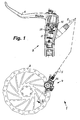
- hydraulic brake system 1 is especially for bicycles, but possibly also for other two-wheeled used. It has a donor system 2 and a braking device 4 attached to a brake disk 3.
- the brake system is filled with hydraulic fluid, wherein the encoder system 2 is connected via a dashed line indicated hydraulic line 5 to the brake device 4.
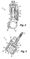
- the transmitter system 2 has a hand-operable brake lever 6, with which a master piston 7 guided in a cylinder 8 (cf., FIG. 2) can be moved while conveying hydraulic fluid via the hydraulic line 5 to the brake device 4.
- This brake device 4 has a brake caliper 36, which is arranged on the brake disc 3 connected to the wheel to be braked. The brake disc 3 is applied during braking on both sides with two brake pads 9 ( Figure 3).
- 10 brake pistons 11 are provided in brake cylinders, which are acted upon by hydraulic fluid on the back.
- the hydraulic fluid is thereby guided from the hydraulic line 5 via channels 12 to the pressure chambers 13 located behind the brake piston 11.
- the transmitter system 2 has a reservoir 14 for hydraulic fluid, which is connected to the cylinder 8 and thus the hydraulic circuit with the brake lever 6 unoperated.
- the donor system 2 on the upper side a filling and venting opening 15 and the braking device 4 also has a filling and venting opening 16 ( Figure 3).
- the brake system 1 is associated with a venting and filling tool 23 with a piston-cylinder assembly and the filling and Vent opening 15 of the encoder system 2 and preferably also the filling and venting opening 16 of the braking device 4 are designed for detachable and tight connection of this venting and filling tool 23.
- the detachable connection between the venting and filling tool 23 and the filling and venting opening 15,16 of the encoder system or the braking device 4 is formed by sealing plugging.
- the venting and filling tool 23 has for this purpose a connecting piece 22 or the like connecting element, which is inserted into the filling and venting opening (s).
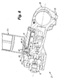
- the filling and vent opening 15 in the lid 17 has a plug-in portion 18, preferably followed by a connection chamber 19 in the encoder housing 20 in alignment with the axial extension.
- the connection chamber 19 is pot-shaped or cup-shaped and has slit-shaped, open-ended overflow openings 21 to the expansion tank 14 at its upper edge. As a result, there is a flow connection between this connection chamber 19 and the expansion tank 14.
- the insertion section 18 of the filling and venting opening 15 is designed to seal the connection piece 22 of the venting and filling tool 23 and has a receiving cone 25 for this purpose.
- the receiving cone 25 is designed for plug-in reception of a connection piece 22 of the venting and filling tool 23 designed as a Luerkonus 24 (FIG. 6).
- a connection piece 22 of the venting and filling tool 23 designed as a Luerkonus 24 (FIG. 6).
- FIGS. 4, 6 and 9 a commercially available syringe as a venting and filling tool 23, as can be seen in FIGS. 4, 6 and 9.
- the plug-in connection with the receiving cone 25 and the connecting piece 22 is dimensioned such that the connecting posts 22 in the inserted position partially projects into the connecting chamber 19, wherein it still has something with its inner end Distance to the bottom of the connection chamber 19 has, as can be seen well in Fig. 6.
- connection chamber 19 has clear dimensions which are larger than those of the protruding part of the connecting piece 22, so that there is still room for an overflow of hydraulic fluid through the overflow openings 21.
- the filling and vent opening 15 of the encoder system 2 is provided on the upper side of this and passes through a compensation tank 14 on the top closing lid 17 ( Figure 4 to 7), which is connected by screwing to the encoder housing 20.
- the formation of a feed channel to the expansion tank 14 forming filling 'and vent 15 on the one hand divided into two preferably axially aligned sections - plug-in section 18, connection chamber 19 and on the other hand arranged in two separately producible parts cover 17, encoder housing 17 has manufacturing technology significant advantages, because it is individual holes that are easy to produce by form pins.
- the feed channel of the filling and venting opening 15 in the functional position is a stepped bore with an inner, larger-diameter step, which in the case of a one-piece design would mean an increased outlay in terms of forming technology because of the undercut.
- the insertion section 18 in the cover 17 and the connection chamber 19 in the encoder housing 20 are aligned with respect to their longitudinal axes so that they each extend in Entformungscardi the lid or the encoder housing and thus enable easy demolding.
- the filling and venting opening 15 is arranged laterally next to the expansion tank 14 and is in filling and venting position according to Figure 6 on the highest side next to the surge tank 14.
- the lid 17 is designed so that it also this, laterally adjacent to the surge tank 14 area of the encoder housing 20 overlaps.
- FIG. 8 shows that the expansion tank 14, which is open without the cover 17 and the bellows 30 (FIG. 13), is well visible, that the connection chamber 19 of the filling and venting opening 15 in a bulge 26 of the transmitter housing 20 projecting laterally into the expansion tank 14 is arranged.
- the connection chamber 19 is surrounded by a boundary wall 27, in which the two slot-shaped, upwardly open-edge overflow openings 21 are located.
- the two overflow openings 21 are arranged laterally offset from the foremost, the surge tank 14 'facing the region of the bulge 26.
- connection chamber 19 It is thereby achieved that, after a filling or venting process, air bubbles which may still be present in the connection chamber 19 can not pass via the overflow openings 21 into the expansion tank 14 in the oblique operating position of the encoder system 2 shown in FIG. 7, but in the somewhat higher-lying part the connection chamber 19 remain trapped. This also contributes to the fact that the overflow openings 21 are formed as narrow edge slots, wherein the slot width for retaining is dimensioned by air bubbles contained in the hydraulic fluid.
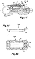
- an elastic bellows 30 is inserted, which, as can be seen in Figure 13, is trough-shaped and has at its opening edge a circumferential, formed as a flange seal 31.
- This bellows 31 is inserted into the expansion tank 14 and fills this area.
- the seal 31 rests on the edge region of the expansion tank and thus on the encoder housing 20.
- the lid 17 is then a closing and sealing both the bellows 30 and the surge tank 14 to the outside.
- the cavity of the bellows 30 is connected through a bellows vent 32 ( Figures 1 and 10) through the lid 17 to the outside atmosphere.
- the seal 31 is provided with a Ringwulst 33, as can be seen well in Figure 6 and 13.
- the lid portion surrounding the insertion portion 18 has an annular groove 34 for sealingly receiving this annular bead 33 (FIG. 12).
- the annular bead 33 rests with its underside on the upper edge of the connection chamber 19 or its boundary wall 27 (FIG. 6).
- the filling and venting opening 15 preferably has a plug-in section 18 with a receiving cone 25, into which the closure plug 35 provided with a matching outer cone can be inserted.
- the seal is made by the cone connection.
- the sealing plug 35 may have an externally accessible insertion cavity as a tool engagement point for a turning tool, which is preferably designed as a hexagon socket for a hexagon key as a turning tool.
- the closure plug 35 can thereby be slightly twisted after insertion of the rotary tool with this and thereby, supported by the cone connection, pulled out.
- the inserted sealing plug can be approximately flush with the outside of the lid or the opening of the Einsteckabêts 18 in the lid 17 or even slightly lower, so that accidental loosening or removal of the sealing plug is practically impossible.
- the closure plug can be made of hard plastic material, for example of the same material as the lid 17. Other materials are also possible, it being only necessary to ensure that the torque for rotating the closure plug 35 can be transmitted by the rotary tool.
- a sealing screw may be provided which is screwed into a threaded bore of the filling and venting opening 15, wherein the seal over the end face is achieved.
- overflow openings 21a are arranged from the connection chamber to the expansion tank instead, as described above, in the boundary wall 27 of the connection chamber 19, in a counterpart resting on the boundary wall, which seal 31 between the cover and the surge tank as part of the bellows 30a.
- the seal 31 is formed by the circumferential side flange of the elastic bellows 30 a (FIGS. 15 and 16).
- This sealing or side flange extends over the region of the connection chamber 19 and its boundary wall 27, wherein in the exemplary embodiment, three channel-shaped overflow 21a (Fig.16) in the bellows side flange and thus the seal 31 are arranged and cover the boundary wall 27, so with their ends on the one hand into the expansion tank 14 and on the other hand into the connection chamber 19 protrude.
- the overflow openings 21a are formed as open-edged grooves, which face the boundary wall 27 with their openings.
- the seal 31 is thickened in the support area on the boundary wall 27 of the connection chamber 19 (FIG. 15), so that on the one hand an increased intrinsic stability is present in this area and, on the other hand, there is space for overflow openings 21a which are adequately dimensioned in cross section.
- the at least one overflow opening 21 from the connection chamber 19 to the expansion tank 14 can also be provided directly in the cover 17, if it consists of suitable material in order to achieve a seal to the connection chamber 19.
- the overflow openings are arranged at the corresponding location as in the seal 31.
- the at least one overflow opening could also be designed as a bore in the side wall of the connection chamber 19. In shaping processes such as injection molding, however, edge-open overflow openings are easier to realize in terms of injection technology.
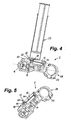
- the encoder system 2 can be connected by means of a holder 28 with the handlebar of a two-wheeler.
- the holder 28 is formed like a clamp and can be tightened or loosened by means of a clamping screw 29.
- the transmitter system can be easily adjusted to the appropriate position on the one hand for operation (FIGS. 5 and 7) and, correspondingly, for good operability and on the other hand for the filling and venting process (FIGS. 4 and 6).
- the donor system 2 from a position with nearly vertical venting and filling tool 23 as shown in Figure 4 and 6, to an approximately horizontal position of the venting and filling 23 well possible is.
- the syringe forming the venting and filling tool 23 can be attached to the top of the encoder system 2 as shown in FIGS. 4, 6 and 9 and tightly inserted into the receiving cone 25 of the filling and venting opening 15 with its connecting piece 22.
- a container with hydraulic fluid can be connected to the filling and venting opening 16, wherein this container can also be a syringe filled with hydraulic fluid.
- the filling and vent opening 16 of the braking device 4 is also provided with a Luer receiving cone, so that here also commercially available syringes can be used as a venting and filling tool 23.
Landscapes
- Engineering & Computer Science (AREA)
- Mechanical Engineering (AREA)
- Transportation (AREA)
- Physics & Mathematics (AREA)
- Fluid Mechanics (AREA)
- Valves And Accessory Devices For Braking Systems (AREA)
- Transmission Of Braking Force In Braking Systems (AREA)
- Braking Arrangements (AREA)
Applications Claiming Priority (1)
| Application Number | Priority Date | Filing Date | Title |
|---|---|---|---|
| DE102006040328A DE102006040328A1 (de) | 2006-08-29 | 2006-08-29 | Bremssystem mit einer hydraulischen Bremsanlage |
Publications (3)
| Publication Number | Publication Date |
|---|---|
| EP1908659A2 true EP1908659A2 (fr) | 2008-04-09 |
| EP1908659A3 EP1908659A3 (fr) | 2009-03-11 |
| EP1908659B1 EP1908659B1 (fr) | 2020-06-17 |
Family
ID=38989538
Family Applications (1)
| Application Number | Title | Priority Date | Filing Date |
|---|---|---|---|
| EP07016149.2A Active EP1908659B1 (fr) | 2006-08-29 | 2007-08-17 | Système de freinage doté d'une installation de freinage hydraulique |
Country Status (4)
| Country | Link |
|---|---|
| US (1) | US20080060885A1 (fr) |
| EP (1) | EP1908659B1 (fr) |
| DE (1) | DE102006040328A1 (fr) |
| TW (1) | TWI376332B (fr) |
Cited By (2)
| Publication number | Priority date | Publication date | Assignee | Title |
|---|---|---|---|---|
| EP3168121A1 (fr) * | 2015-11-13 | 2017-05-17 | Giant Manufacturing Co., Ltd | Dispositif de frein à disque hydraulique pour bicyclette |
| CN107010157A (zh) * | 2015-11-13 | 2017-08-04 | 巨大机械工业股份有限公司 | 自行车的油压碟煞装置 |
Families Citing this family (24)
| Publication number | Priority date | Publication date | Assignee | Title |
|---|---|---|---|---|
| DE102006040327A1 (de) * | 2006-08-29 | 2008-03-06 | Gustav Magenwirth Gmbh & Co. Kg | Bremssystem mit einer hydraulischen Bremsanlage |
| US7988173B2 (en) * | 2008-09-05 | 2011-08-02 | Sram, Llc | Bicycle suspension system |
| US7832531B2 (en) * | 2009-03-06 | 2010-11-16 | Shimano Inc. | Bicycle component fixing band |
| DE102009039620A1 (de) | 2009-09-01 | 2011-03-03 | Gustav Magenwirth Gmbh & Co. Kg | Gebervorrichtung für ein geschlossenes Hydrauliksystem lenkergeführter Fahrzeuge |
| TWI382943B (zh) * | 2010-08-20 | 2013-01-21 | Ashima Ltd | Hydraulic brake sealing device |
| USD641670S1 (en) | 2010-11-24 | 2011-07-19 | Hb Performance Systems, Inc. | Brake pad |
| US8943924B2 (en) | 2010-11-24 | 2015-02-03 | Hb Performance Systems, Inc. | System and method for an adjustable lever assembly |
| DE102010053009A1 (de) * | 2010-12-02 | 2012-06-06 | Jürgen Lauhoff | Betätigungsvorrichtung für eine Bremszange und Bremsanlage |
| US9550544B2 (en) | 2012-07-26 | 2017-01-24 | Shimano Inc. | Bicycle handlebar clamp assembly |
| US9199691B2 (en) * | 2012-08-03 | 2015-12-01 | Shimano Inc. | Hydraulic bicycle component kit |
| US10131339B2 (en) | 2012-08-03 | 2018-11-20 | Shimano Inc. | Hydraulic bicycle component |
| EP3038893B1 (fr) * | 2013-08-27 | 2019-11-20 | Gustav Magenwirth GmbH & Co. KG | Maître-cylindre |
| US20160059926A1 (en) * | 2014-08-29 | 2016-03-03 | Shimano Inc. | Hydraulic operating device for a bicycle |
| US9827968B2 (en) * | 2015-01-12 | 2017-11-28 | Sram, Llc | Hydraulic bicycle system |
| IT201600103768A1 (it) | 2016-10-17 | 2018-04-17 | Campagnolo Srl | Valvola di spurgo per impianto frenante idraulico di bicicletta |
| DE102016123358B4 (de) | 2016-12-02 | 2020-12-03 | Saf-Holland Gmbh | Vorrichtung zum Betätigen einer Bremse, eine Bremse und ein Verfahren zum Herstellen oder Aufrüsten einer Vorrichtung zum Betätigen einer Bremse |
| CN108679202B (zh) * | 2018-06-20 | 2024-06-21 | 唐泽制动器(天津)有限公司 | 一种变速器用制动盘组合件 |
| CN110203377A (zh) * | 2019-05-21 | 2019-09-06 | 成都飞机工业(集团)有限责任公司 | 一种无人机刹车油液免排气加注装置及方法 |
| IT201900023994A1 (it) | 2019-12-13 | 2021-06-13 | Campagnolo Srl | Serbatoio idraulico per bicicletta |
| IT201900023988A1 (it) * | 2019-12-13 | 2021-06-13 | Campagnolo Srl | Serbatoio idraulico per bicicletta |
| IT202100020564A1 (it) * | 2021-07-30 | 2023-01-30 | Campagnolo Srl | Sistema e metodo di diagnosi di un impianto frenante idraulico di bicicletta del tipo a disco |
| IT202100020558A1 (it) | 2021-07-30 | 2023-01-30 | Campagnolo Srl | Impianto frenante idraulico di bicicletta del tipo a disco e componenti e metodi correlati |
| DE102022121163A1 (de) * | 2022-08-22 | 2024-02-22 | Trickstuff Gmbh | Hydraulische Bremsanordnung für ein wenigstens teilweise muskelbetriebenes Fahrrad |
| US12037076B1 (en) * | 2023-03-09 | 2024-07-16 | Shimano Inc. | Hydraulic reservoir and operating device of human-powered vehicle |
Citations (1)
| Publication number | Priority date | Publication date | Assignee | Title |
|---|---|---|---|---|
| US4785629A (en) | 1987-06-04 | 1988-11-22 | Ennis Iii James F | Syringe-dispensed brake fluid for filling and purging master cylinder circuit from slave |
Family Cites Families (24)
| Publication number | Priority date | Publication date | Assignee | Title |
|---|---|---|---|---|
| DE676240C (de) * | 1936-09-30 | 1939-05-30 | Rotadisk Appbau G M B H | Geraet zum Fuellen von Bremsen und Bremsleitungsnetzen mit der Bremsfluessigkeit |
| US2524544A (en) * | 1948-03-02 | 1950-10-03 | Harry T Seawell | Hydraulic brake bleeder system |
| US4170280A (en) * | 1978-03-14 | 1979-10-09 | Parker-Hannifin Corporation | Bleeder harness for brake master cylinders |
| US4201056A (en) * | 1978-05-01 | 1980-05-06 | Kent-Moore Corporation | Brake bleeder adapter |
| US4236549A (en) * | 1978-05-12 | 1980-12-02 | Autoline Supply Company | Bleeder kit for bleeding a master cylinder |
| GB2111148B (en) * | 1981-06-09 | 1985-09-18 | Nisshin Kogyo Kk | Diaphragm assembly |
| US4788821A (en) * | 1983-11-28 | 1988-12-06 | Automotive Products, Plc | Hydraulic shift for motor vehicle transmission |
| GB8602486D0 (en) * | 1986-01-31 | 1986-03-05 | Liquid Levers Ltd | Fluid system bleeding apparatus |
| FR2654693B1 (fr) * | 1989-11-22 | 1992-02-28 | Ciliento Felice | Assortiment de pieces de rechange et d'entretien pour un circuit hydraulique de freinage, et procede pour remplir un tel circuit. |
| US5088529A (en) * | 1990-08-27 | 1992-02-18 | General Motors Corporation | Vehicle brake vacuum evacuation and brake fluid fill machine |
| AU635631B2 (en) * | 1991-01-15 | 1993-03-25 | Astra Pharmaceuticals Pty Ltd | Plastic syringe |
| US5497864A (en) * | 1995-06-20 | 1996-03-12 | Chrysler Corporation | Hydraulic brake bleeder apparatus |
| KR0120417B1 (en) * | 1995-07-19 | 1997-11-04 | Hyundai Motor Co Ltd | Oil-compensating device for brake device |
| US5950772A (en) * | 1997-08-29 | 1999-09-14 | Hayes Brake, Inc. | Bicycle brake system having a flexible disk |
| JP2002506408A (ja) * | 1998-04-28 | 2002-02-26 | ロックショックス インコーポレイテッド | ディスクブレーキシステム用の同心状の補正室とマスターシリンダ |
| US5967199A (en) * | 1998-05-13 | 1999-10-19 | General Motors Corporation | Pressurized brake bleed system |
| US6298961B1 (en) * | 2000-03-02 | 2001-10-09 | Delphi Technologies, Inc. | Reservoir cap and bleed mechanism |
| DE20015042U1 (de) * | 2000-08-30 | 2000-11-16 | Stalla & Dittrich GmbH, 71691 Freiberg | Entlüftereinrichtung |
| JP4965058B2 (ja) * | 2000-11-30 | 2012-07-04 | フレニ・ブレンボ エス・ピー・エー | ハンドルバーによって制御可能な車両用のマスターシリンダー |
| US6871729B2 (en) * | 2001-03-02 | 2005-03-29 | Freni Brembo S.P.A. | Master cylinder for a brake or clutch of a motorcycle or bike |
| DE20108558U1 (de) * | 2001-05-22 | 2001-08-09 | Krebs, Peter, Dr., 78048 Villingen-Schwenningen | Kombinationsnadel für die peripheren Nervenblockaden |
| US6581905B2 (en) * | 2001-11-21 | 2003-06-24 | Tenneco Automotive Inc. | Brake bleed tool |
| CN1930038A (zh) * | 2004-03-09 | 2007-03-14 | 海斯自行车集团公司 | 杆组件以及制动主缸 |
| DE102006040327A1 (de) * | 2006-08-29 | 2008-03-06 | Gustav Magenwirth Gmbh & Co. Kg | Bremssystem mit einer hydraulischen Bremsanlage |
-
2006
- 2006-08-29 DE DE102006040328A patent/DE102006040328A1/de not_active Withdrawn
-
2007
- 2007-08-17 EP EP07016149.2A patent/EP1908659B1/fr active Active
- 2007-08-24 TW TW096131339A patent/TWI376332B/zh active
- 2007-08-29 US US11/846,548 patent/US20080060885A1/en not_active Abandoned
Patent Citations (1)
| Publication number | Priority date | Publication date | Assignee | Title |
|---|---|---|---|---|
| US4785629A (en) | 1987-06-04 | 1988-11-22 | Ennis Iii James F | Syringe-dispensed brake fluid for filling and purging master cylinder circuit from slave |
Cited By (5)
| Publication number | Priority date | Publication date | Assignee | Title |
|---|---|---|---|---|
| EP3168121A1 (fr) * | 2015-11-13 | 2017-05-17 | Giant Manufacturing Co., Ltd | Dispositif de frein à disque hydraulique pour bicyclette |
| JP2017088169A (ja) * | 2015-11-13 | 2017-05-25 | 巨大機械工業股▲分▼有限公司 | 自転車用の油圧ディスクブレーキ装置 |
| CN107010157A (zh) * | 2015-11-13 | 2017-08-04 | 巨大机械工业股份有限公司 | 自行车的油压碟煞装置 |
| CN107010157B (zh) * | 2015-11-13 | 2019-06-07 | 巨大机械工业股份有限公司 | 自行车的油压碟煞装置 |
| US10407123B2 (en) | 2015-11-13 | 2019-09-10 | Giant Manufacturing Co., Ltd. | Hydraulic disc brake device for a bicycle |
Also Published As
| Publication number | Publication date |
|---|---|
| TW200846240A (en) | 2008-12-01 |
| US20080060885A1 (en) | 2008-03-13 |
| DE102006040328A1 (de) | 2008-03-06 |
| EP1908659A3 (fr) | 2009-03-11 |
| EP1908659B1 (fr) | 2020-06-17 |
| TWI376332B (en) | 2012-11-11 |
Similar Documents
| Publication | Publication Date | Title |
|---|---|---|
| EP1908659B1 (fr) | Système de freinage doté d'une installation de freinage hydraulique | |
| EP1894831B1 (fr) | Dispositif de freinage avec un système hydraulique de freinage | |
| EP1446232B1 (fr) | Recipient de pistolet-pulverisateur pourvu d'une piece interne solide | |
| EP1992395B1 (fr) | Filtre, en particulier filtre à air | |
| DE19511450A1 (de) | Nebenstromfilteraggregat | |
| DE3036076A1 (de) | Ausspuel- und absaughandstueck | |
| DE102008002765B4 (de) | Spendereinheit sowie Verfahren zum Befüllen und Evakuieren einer Spendereinheit und Fülleinsatz für eine Spendereinheit für pastöse, schaumförmige oder flüssige Medien | |
| DE19625372A1 (de) | Verfahren zum Entfernen von Pannen-Abdichtmitteln aus Reifen und Vorrichtungen zur Durchführung der Verfahren | |
| DE102007035386B4 (de) | Entlüftungsvorrichtung | |
| EP2440437A1 (fr) | Accouplement de raccordement pour une vis de purge d'un système hydraulique | |
| DE19832824A1 (de) | Abgabepumpe für die Abgabe von Flüssigkeiten, Gelen oder dgl. Medien | |
| DE202005021403U1 (de) | Einrichtung zum Zuführen von Dichtungsflüssigkeit in einen Luftreifen | |
| EP2594220B1 (fr) | Dispositif de raccordement pour un dispositif de nettoyage d'instruments dotés d'au moins une lumière devant être nettoyée | |
| DE20113129U1 (de) | Behälter für eine Reifenflickflüssigkeit in einem Reifenflicksatz | |
| DE69016953T2 (de) | Zusammenstellung von Ersatz- und Wartungsteilen für ein Flüssigkeitsbremssystem und Verfahren zum Füllen eines solchen Systems. | |
| DE202008012804U1 (de) | Dose für Autoreifenabdichtmittel | |
| DE3322226C1 (de) | Vorrichtung zur automatischen Spuelung von Melkeimern | |
| EP2688781A1 (fr) | Contenant de fluide hydraulique pour un système de freinage hydraulique d'automobile et procédé de remplissage | |
| EP1571101B1 (fr) | Dispositif de stockage et de distribution de fluide | |
| CH686527A5 (de) | Vorrichtung zum Aufpumpen von Reifen. | |
| EP2006021A1 (fr) | Partie supérieure de pipetage | |
| DE4445623C1 (de) | Handgerät zur Absaugung von Altöl aus Kraftfahrzeugen | |
| DE1455770C (de) | Flussigkeitstank fur Fahrzeuge | |
| DE927433C (de) | Druckluftanlage in Kraftfahrzeugen | |
| DE202021101834U1 (de) | Deckel für ein Wasseraufbereitungsmodul |
Legal Events
| Date | Code | Title | Description |
|---|---|---|---|
| PUAI | Public reference made under article 153(3) epc to a published international application that has entered the european phase |
Free format text: ORIGINAL CODE: 0009012 |
|
| AK | Designated contracting states |
Kind code of ref document: A2 Designated state(s): AT BE BG CH CY CZ DE DK EE ES FI FR GB GR HU IE IS IT LI LT LU LV MC MT NL PL PT RO SE SI SK TR |
|
| AX | Request for extension of the european patent |
Extension state: AL BA HR MK RS |
|
| PUAL | Search report despatched |
Free format text: ORIGINAL CODE: 0009013 |
|
| AK | Designated contracting states |
Kind code of ref document: A3 Designated state(s): AT BE BG CH CY CZ DE DK EE ES FI FR GB GR HU IE IS IT LI LT LU LV MC MT NL PL PT RO SE SI SK TR |
|
| AX | Request for extension of the european patent |
Extension state: AL BA HR MK RS |
|
| RIC1 | Information provided on ipc code assigned before grant |
Ipc: B60T 17/22 20060101ALI20090204BHEP Ipc: B62L 3/02 20060101ALI20090204BHEP Ipc: B60T 11/30 20060101ALI20090204BHEP Ipc: B60T 11/22 20060101AFI20080229BHEP |
|
| 17Q | First examination report despatched |
Effective date: 20090925 |
|
| 17P | Request for examination filed |
Effective date: 20090827 |
|
| AKX | Designation fees paid |
Designated state(s): AT BE BG CH CY CZ DE DK EE ES FI FR GB GR HU IE IS IT LI LT LU LV MC MT NL PL PT RO SE SI SK TR |
|
| STAA | Information on the status of an ep patent application or granted ep patent |
Free format text: STATUS: EXAMINATION IS IN PROGRESS |
|
| GRAP | Despatch of communication of intention to grant a patent |
Free format text: ORIGINAL CODE: EPIDOSNIGR1 |
|
| STAA | Information on the status of an ep patent application or granted ep patent |
Free format text: STATUS: GRANT OF PATENT IS INTENDED |
|
| INTG | Intention to grant announced |
Effective date: 20200303 |
|
| GRAS | Grant fee paid |
Free format text: ORIGINAL CODE: EPIDOSNIGR3 |
|
| GRAA | (expected) grant |
Free format text: ORIGINAL CODE: 0009210 |
|
| STAA | Information on the status of an ep patent application or granted ep patent |
Free format text: STATUS: THE PATENT HAS BEEN GRANTED |
|
| AK | Designated contracting states |
Kind code of ref document: B1 Designated state(s): AT BE BG CH CY CZ DE DK EE ES FI FR GB GR HU IE IS IT LI LT LU LV MC MT NL PL PT RO SE SI SK TR |
|
| REG | Reference to a national code |
Ref country code: GB Ref legal event code: FG4D Free format text: NOT ENGLISH |
|
| REG | Reference to a national code |
Ref country code: CH Ref legal event code: EP |
|
| REG | Reference to a national code |
Ref country code: DE Ref legal event code: R096 Ref document number: 502007016889 Country of ref document: DE |
|
| REG | Reference to a national code |
Ref country code: IE Ref legal event code: FG4D Free format text: LANGUAGE OF EP DOCUMENT: GERMAN |
|
| REG | Reference to a national code |
Ref country code: AT Ref legal event code: REF Ref document number: 1280944 Country of ref document: AT Kind code of ref document: T Effective date: 20200715 |
|
| PG25 | Lapsed in a contracting state [announced via postgrant information from national office to epo] |
Ref country code: LT Free format text: LAPSE BECAUSE OF FAILURE TO SUBMIT A TRANSLATION OF THE DESCRIPTION OR TO PAY THE FEE WITHIN THE PRESCRIBED TIME-LIMIT Effective date: 20200617 Ref country code: SE Free format text: LAPSE BECAUSE OF FAILURE TO SUBMIT A TRANSLATION OF THE DESCRIPTION OR TO PAY THE FEE WITHIN THE PRESCRIBED TIME-LIMIT Effective date: 20200617 Ref country code: FI Free format text: LAPSE BECAUSE OF FAILURE TO SUBMIT A TRANSLATION OF THE DESCRIPTION OR TO PAY THE FEE WITHIN THE PRESCRIBED TIME-LIMIT Effective date: 20200617 Ref country code: GR Free format text: LAPSE BECAUSE OF FAILURE TO SUBMIT A TRANSLATION OF THE DESCRIPTION OR TO PAY THE FEE WITHIN THE PRESCRIBED TIME-LIMIT Effective date: 20200918 |
|
| REG | Reference to a national code |
Ref country code: LT Ref legal event code: MG4D |
|
| REG | Reference to a national code |
Ref country code: NL Ref legal event code: MP Effective date: 20200617 |
|
| PG25 | Lapsed in a contracting state [announced via postgrant information from national office to epo] |
Ref country code: LV Free format text: LAPSE BECAUSE OF FAILURE TO SUBMIT A TRANSLATION OF THE DESCRIPTION OR TO PAY THE FEE WITHIN THE PRESCRIBED TIME-LIMIT Effective date: 20200617 Ref country code: BG Free format text: LAPSE BECAUSE OF FAILURE TO SUBMIT A TRANSLATION OF THE DESCRIPTION OR TO PAY THE FEE WITHIN THE PRESCRIBED TIME-LIMIT Effective date: 20200917 |
|
| PG25 | Lapsed in a contracting state [announced via postgrant information from national office to epo] |
Ref country code: NL Free format text: LAPSE BECAUSE OF FAILURE TO SUBMIT A TRANSLATION OF THE DESCRIPTION OR TO PAY THE FEE WITHIN THE PRESCRIBED TIME-LIMIT Effective date: 20200617 |
|
| PG25 | Lapsed in a contracting state [announced via postgrant information from national office to epo] |
Ref country code: PT Free format text: LAPSE BECAUSE OF FAILURE TO SUBMIT A TRANSLATION OF THE DESCRIPTION OR TO PAY THE FEE WITHIN THE PRESCRIBED TIME-LIMIT Effective date: 20201019 Ref country code: CZ Free format text: LAPSE BECAUSE OF FAILURE TO SUBMIT A TRANSLATION OF THE DESCRIPTION OR TO PAY THE FEE WITHIN THE PRESCRIBED TIME-LIMIT Effective date: 20200617 Ref country code: RO Free format text: LAPSE BECAUSE OF FAILURE TO SUBMIT A TRANSLATION OF THE DESCRIPTION OR TO PAY THE FEE WITHIN THE PRESCRIBED TIME-LIMIT Effective date: 20200617 Ref country code: EE Free format text: LAPSE BECAUSE OF FAILURE TO SUBMIT A TRANSLATION OF THE DESCRIPTION OR TO PAY THE FEE WITHIN THE PRESCRIBED TIME-LIMIT Effective date: 20200617 Ref country code: ES Free format text: LAPSE BECAUSE OF FAILURE TO SUBMIT A TRANSLATION OF THE DESCRIPTION OR TO PAY THE FEE WITHIN THE PRESCRIBED TIME-LIMIT Effective date: 20200617 |
|
| PG25 | Lapsed in a contracting state [announced via postgrant information from national office to epo] |
Ref country code: IS Free format text: LAPSE BECAUSE OF FAILURE TO SUBMIT A TRANSLATION OF THE DESCRIPTION OR TO PAY THE FEE WITHIN THE PRESCRIBED TIME-LIMIT Effective date: 20201017 Ref country code: PL Free format text: LAPSE BECAUSE OF FAILURE TO SUBMIT A TRANSLATION OF THE DESCRIPTION OR TO PAY THE FEE WITHIN THE PRESCRIBED TIME-LIMIT Effective date: 20200617 Ref country code: SK Free format text: LAPSE BECAUSE OF FAILURE TO SUBMIT A TRANSLATION OF THE DESCRIPTION OR TO PAY THE FEE WITHIN THE PRESCRIBED TIME-LIMIT Effective date: 20200617 |
|
| REG | Reference to a national code |
Ref country code: DE Ref legal event code: R097 Ref document number: 502007016889 Country of ref document: DE |
|
| PG25 | Lapsed in a contracting state [announced via postgrant information from national office to epo] |
Ref country code: MC Free format text: LAPSE BECAUSE OF FAILURE TO SUBMIT A TRANSLATION OF THE DESCRIPTION OR TO PAY THE FEE WITHIN THE PRESCRIBED TIME-LIMIT Effective date: 20200617 |
|
| REG | Reference to a national code |
Ref country code: CH Ref legal event code: PL |
|
| PLBE | No opposition filed within time limit |
Free format text: ORIGINAL CODE: 0009261 |
|
| STAA | Information on the status of an ep patent application or granted ep patent |
Free format text: STATUS: NO OPPOSITION FILED WITHIN TIME LIMIT |
|
| PG25 | Lapsed in a contracting state [announced via postgrant information from national office to epo] |
Ref country code: LI Free format text: LAPSE BECAUSE OF NON-PAYMENT OF DUE FEES Effective date: 20200831 Ref country code: DK Free format text: LAPSE BECAUSE OF FAILURE TO SUBMIT A TRANSLATION OF THE DESCRIPTION OR TO PAY THE FEE WITHIN THE PRESCRIBED TIME-LIMIT Effective date: 20200617 Ref country code: CH Free format text: LAPSE BECAUSE OF NON-PAYMENT OF DUE FEES Effective date: 20200831 Ref country code: LU Free format text: LAPSE BECAUSE OF NON-PAYMENT OF DUE FEES Effective date: 20200817 |
|
| 26N | No opposition filed |
Effective date: 20210318 |
|
| REG | Reference to a national code |
Ref country code: BE Ref legal event code: MM Effective date: 20200831 |
|
| PG25 | Lapsed in a contracting state [announced via postgrant information from national office to epo] |
Ref country code: SI Free format text: LAPSE BECAUSE OF FAILURE TO SUBMIT A TRANSLATION OF THE DESCRIPTION OR TO PAY THE FEE WITHIN THE PRESCRIBED TIME-LIMIT Effective date: 20200617 |
|
| PG25 | Lapsed in a contracting state [announced via postgrant information from national office to epo] |
Ref country code: BE Free format text: LAPSE BECAUSE OF NON-PAYMENT OF DUE FEES Effective date: 20200831 Ref country code: IE Free format text: LAPSE BECAUSE OF NON-PAYMENT OF DUE FEES Effective date: 20200817 |
|
| PG25 | Lapsed in a contracting state [announced via postgrant information from national office to epo] |
Ref country code: TR Free format text: LAPSE BECAUSE OF FAILURE TO SUBMIT A TRANSLATION OF THE DESCRIPTION OR TO PAY THE FEE WITHIN THE PRESCRIBED TIME-LIMIT Effective date: 20200617 Ref country code: MT Free format text: LAPSE BECAUSE OF FAILURE TO SUBMIT A TRANSLATION OF THE DESCRIPTION OR TO PAY THE FEE WITHIN THE PRESCRIBED TIME-LIMIT Effective date: 20200617 Ref country code: CY Free format text: LAPSE BECAUSE OF FAILURE TO SUBMIT A TRANSLATION OF THE DESCRIPTION OR TO PAY THE FEE WITHIN THE PRESCRIBED TIME-LIMIT Effective date: 20200617 |
|
| PGFP | Annual fee paid to national office [announced via postgrant information from national office to epo] |
Ref country code: DE Payment date: 20240819 Year of fee payment: 18 |
|
| PGFP | Annual fee paid to national office [announced via postgrant information from national office to epo] |
Ref country code: GB Payment date: 20240821 Year of fee payment: 18 |
|
| PGFP | Annual fee paid to national office [announced via postgrant information from national office to epo] |
Ref country code: FR Payment date: 20240823 Year of fee payment: 18 |
|
| PGFP | Annual fee paid to national office [announced via postgrant information from national office to epo] |
Ref country code: AT Payment date: 20240823 Year of fee payment: 18 |
|
| PGFP | Annual fee paid to national office [announced via postgrant information from national office to epo] |
Ref country code: IT Payment date: 20240827 Year of fee payment: 18 |
|
| REG | Reference to a national code |
Ref country code: DE Ref legal event code: R119 Ref document number: 502007016889 Country of ref document: DE |
|
| PG25 | Lapsed in a contracting state [announced via postgrant information from national office to epo] |
Ref country code: AT Free format text: LAPSE BECAUSE OF NON-PAYMENT OF DUE FEES Effective date: 20250817 |
|
| REG | Reference to a national code |
Ref country code: AT Ref legal event code: MM01 Ref document number: 1280944 Country of ref document: AT Kind code of ref document: T Effective date: 20250817 |