EP1908659A2 - Braking system with a hydraulic braking system - Google Patents
Braking system with a hydraulic braking system Download PDFInfo
- Publication number
- EP1908659A2 EP1908659A2 EP07016149A EP07016149A EP1908659A2 EP 1908659 A2 EP1908659 A2 EP 1908659A2 EP 07016149 A EP07016149 A EP 07016149A EP 07016149 A EP07016149 A EP 07016149A EP 1908659 A2 EP1908659 A2 EP 1908659A2
- Authority
- EP
- European Patent Office
- Prior art keywords
- filling
- venting
- opening
- brake system
- boundary wall
- Prior art date
- Legal status (The legal status is an assumption and is not a legal conclusion. Google has not performed a legal analysis and makes no representation as to the accuracy of the status listed.)
- Granted
Links
Images


Classifications
-
- B—PERFORMING OPERATIONS; TRANSPORTING
- B60—VEHICLES IN GENERAL
- B60T—VEHICLE BRAKE CONTROL SYSTEMS OR PARTS THEREOF; BRAKE CONTROL SYSTEMS OR PARTS THEREOF, IN GENERAL; ARRANGEMENT OF BRAKING ELEMENTS ON VEHICLES IN GENERAL; PORTABLE DEVICES FOR PREVENTING UNWANTED MOVEMENT OF VEHICLES; VEHICLE MODIFICATIONS TO FACILITATE COOLING OF BRAKES
- B60T11/00—Transmitting braking action from initiating means to ultimate brake actuator without power assistance or drive or where such assistance or drive is irrelevant
- B60T11/10—Transmitting braking action from initiating means to ultimate brake actuator without power assistance or drive or where such assistance or drive is irrelevant transmitting by fluid means, e.g. hydraulic
- B60T11/16—Master control, e.g. master cylinders
- B60T11/22—Master control, e.g. master cylinders characterised by being integral with reservoir
-
- B—PERFORMING OPERATIONS; TRANSPORTING
- B60—VEHICLES IN GENERAL
- B60T—VEHICLE BRAKE CONTROL SYSTEMS OR PARTS THEREOF; BRAKE CONTROL SYSTEMS OR PARTS THEREOF, IN GENERAL; ARRANGEMENT OF BRAKING ELEMENTS ON VEHICLES IN GENERAL; PORTABLE DEVICES FOR PREVENTING UNWANTED MOVEMENT OF VEHICLES; VEHICLE MODIFICATIONS TO FACILITATE COOLING OF BRAKES
- B60T11/00—Transmitting braking action from initiating means to ultimate brake actuator without power assistance or drive or where such assistance or drive is irrelevant
- B60T11/10—Transmitting braking action from initiating means to ultimate brake actuator without power assistance or drive or where such assistance or drive is irrelevant transmitting by fluid means, e.g. hydraulic
- B60T11/28—Valves specially adapted therefor
- B60T11/30—Bleed valves for hydraulic brake systems
-
- B—PERFORMING OPERATIONS; TRANSPORTING
- B60—VEHICLES IN GENERAL
- B60T—VEHICLE BRAKE CONTROL SYSTEMS OR PARTS THEREOF; BRAKE CONTROL SYSTEMS OR PARTS THEREOF, IN GENERAL; ARRANGEMENT OF BRAKING ELEMENTS ON VEHICLES IN GENERAL; PORTABLE DEVICES FOR PREVENTING UNWANTED MOVEMENT OF VEHICLES; VEHICLE MODIFICATIONS TO FACILITATE COOLING OF BRAKES
- B60T17/00—Component parts, details, or accessories of power brake systems not covered by groups B60T8/00, B60T13/00 or B60T15/00, or presenting other characteristic features
- B60T17/18—Safety devices; Monitoring
- B60T17/22—Devices for monitoring or checking brake systems; Signal devices
- B60T17/221—Procedure or apparatus for checking or keeping in a correct functioning condition of brake systems
- B60T17/222—Procedure or apparatus for checking or keeping in a correct functioning condition of brake systems by filling or bleeding of hydraulic systems
-
- B—PERFORMING OPERATIONS; TRANSPORTING
- B62—LAND VEHICLES FOR TRAVELLING OTHERWISE THAN ON RAILS
- B62L—BRAKES SPECIALLY ADAPTED FOR CYCLES
- B62L3/00—Brake-actuating mechanisms; Arrangements thereof
- B62L3/02—Brake-actuating mechanisms; Arrangements thereof for control by a hand lever
- B62L3/023—Brake-actuating mechanisms; Arrangements thereof for control by a hand lever acting on fluid pressure systems
Definitions
- the invention relates to a brake system with a hydraulic brake system for two-wheelers, especially bicycles, with a filling device for the brake system, wherein the brake system has a filled with hydraulic fluid donor system and a hydraulically connected brake device, wherein the donor system a surge tank and a filling and Having vent.
- the hydraulic system can have a closable opening in the region of the brake device located on the wheel, in particular on the brake caliper, and the filling and venting opening of the compensation reservoir on the transmitter system.
- the brake fluid is filled under pressure through the opening on the brake calliper (brake caliper valve) until brake fluid escapes without bubbles when the expansion tank is removed from the top of the expansion tank and the filling and venting hole is removed.
- Object of the present invention is in a Braking system of the type mentioned to simplify the filling and bleeding of the hydraulic system and make it safer, so that a simple and while avoiding contamination of the environment with hydraulic fluid - sabberschreib - filling and venting of the brake system is possible.
- the brake system is associated with a venting and filling tool with a piston-cylinder assembly and that at least the filling and venting of the encoder system is designed for releasably connecting this venting and filling tool.
- the releasable connection between the venting and filling tool and the filling and venting of the encoder system is formed by sealing plugging.
- venting and filling tool By sealingly inserting the venting and filling tool, filling and / or venting of the hydraulic system can be carried out essentially without any further aids.
- the filling and venting opening of the donor system is expediently arranged on the upper side thereof and in particular in a cover of the compensation container.
- the filling and venting is thus at the top of the encoder system, whereby a favorable position for filling and venting is given.
- the direction of orientation of the filling and venting opening is, in particular, oriented substantially vertically or somewhat obliquely, so that the venting and filling tool can be inserted from above.
- the venting and filling tool has a connection piece or the like connection element for sealing insertion into the filling and vent opening (s).
- the venting and filling tool can be plugged with its connection piece directly into the filling and venting and is then held in approximately vertical or slightly inclined position. Additional. Tools for holding are not required.
- a conical connection between the connecting piece and filling and venting a tight and secure connection is alone by the insertion, which is pressure and vacuum tight and contributes to a simple and clean handling during filling and ventilation process.
- the connecting piece of the venting and filling tool has a Luerkonus or a Luer-Lock and if the filling and Vent opening of the expansion tank is designed to match the connection piece. Both the Luerkonus for insertion and the Luer-Lock for screwing form proven, easy to handle, tight and secure connections.
- Luerkonus or Luer-Lock cone compound When using a Luerkonus or Luer-Lock cone compound can be used in a particularly advantageous manner as a venting and filling a commercial syringe, which is practically everywhere available and inexpensive and their usual filling volume of, for example, 10 ml or 20 ml for a complete filling and / or venting a hydraulic system sufficient in particular for bicycles, without having to be on and off several times.
- the braking device has a filling and venting opening, which is designed for releasable connection of the venting and filling tool by preferably sealing plugging.
- the filling and venting opening of the braking device is designed to fit the connection piece of the venting and filling tool, which is formed in particular by a syringe.
- a syringe filled with hydraulic fluid or another container with hydraulic fluid can be connected to the brake device, while an empty syringe for the suction at the filling and venting opening is tightly docked.
- the hydraulic fluid is sucked through the hydraulic system, which if necessary supportive by simultaneously pressing the lower filled syringe rapid filling and venting is possible.
- the bleeding and filling tool can also be integrated in the encoder system, ie be part of the encoder system. It can be permanently connected to the expansion tank or held in a holder and removable for the filling and venting process or removable and can be tightly connected to the filling and venting.
- At least the filling and venting of the donor system in a surge tank cover have a plug-in for sealingly receiving the connection piece of the venting and filling, wherein the insertion in the insertion direction a preferably cup-shaped connection chamber in the encoder housing connects, in the one Part of the connecting piece protrudes and has at least one connection to the expansion tank.
- the filling and venting opening is arranged at the top of the encoder system and thus at a favorable position for filling and venting.
- the insertion section in the cover, and the cup-shaped connection chamber in the encoder housing are aligned with each other and are expediently oriented in Entformungscardi a mold for producing these parts, so that a simple production is possible.
- the venting and filling tool or its connection piece is securely held after insertion and via the connection chamber and the overflow opening a flow connection to the expansion tank is provided in a simple manner. Due to the secure mounting of the bleeding and filling tool, when draining, filling and bleeding the hydraulic system, no brake fluid is achieved or hydraulic fluid leaks and causes damage to vehicle parts or makes them useless. Also, a skin contact with hydraulic fluid is safely avoided. For the aforementioned reasons, a comparatively extensive, cumbersome to handle equipment is used for handling brake fluid during filling and venting that can cause problems for an untrained user.
- connection chamber expediently has a lateral boundary wall to the expansion tank, in which at least one overflow opening open at the top is provided as a connection to the expansion tank. Also, this open-edge overflow opening, which is likewise oriented in the removal direction of a mold as the insertion section and the connection chamber, contributes to a simple construction of the mold and to a simplified production.
- connection chamber has clear inner dimensions which are larger than the protruding part of the connection piece and that the edge-open overflow opening is arranged in the boundary wall of the connection chamber in the operating position of the encoder system in a region spaced from the highest point of the lateral boundary wall. Due to this dimensioning of the connection chamber, there is sufficient space around the connection piece for circulating the fluid (hydraulic fluid, air) so that it can reach the connection chamber via the overflow opening and vice versa. By the special. Position of the edge-open overflow opening, the connection chamber forms an air trap for air bubbles in the hydraulic fluid. These stay trapped by the deeper arrangement of the overflow in relation to the highest point of the interior or of its boundary wall in the connection chamber and can not get into the expansion tank and the other hydraulic circuit.
- two preferably oppositely arranged, open-top overflow openings may be provided in the boundary wall. These are then expediently positioned in each case offset to the highest point of the interior of the connection chamber by about 90 ° or more.
- the overflow opening (or several overflow openings) arranged in the boundary wall of the connection chamber is designed as a narrow edge slot, the slot width being dimensioned for retaining air bubbles contained in the hydraulic fluid. In particular, air bubbles which rise due to gravity in the hydraulic fluid are retained.
- the overflow opening may be arranged from the connection chamber to the expansion tank instead of in the boundary wall of the connection chamber in a resting on the boundary wall counterpart.
- the counterpart resting on the boundary wall may in particular be the cover or a seal between the cover and the expansion tank.
- the overflow opening (s) from the connection chamber to the expansion tank can in such a case be provided in the cover itself or in a seal between the cover and the expansion tank.
- the overflow opening (s) can be channel-shaped in their area covering the boundary wall as an open-edged groove which, with its opening, faces the boundary wall and overlaps it. It is preferably provided that the seal with the at least one overflow opening is the circumferential side flange of the elastic bellows.
- hydraulic brake system 1 is especially for bicycles, but possibly also for other two-wheeled used. It has a donor system 2 and a braking device 4 attached to a brake disk 3.
- the brake system is filled with hydraulic fluid, wherein the encoder system 2 is connected via a dashed line indicated hydraulic line 5 to the brake device 4.
- the transmitter system 2 has a hand-operable brake lever 6, with which a master piston 7 guided in a cylinder 8 (cf., FIG. 2) can be moved while conveying hydraulic fluid via the hydraulic line 5 to the brake device 4.
- This brake device 4 has a brake caliper 36, which is arranged on the brake disc 3 connected to the wheel to be braked. The brake disc 3 is applied during braking on both sides with two brake pads 9 ( Figure 3).
- 10 brake pistons 11 are provided in brake cylinders, which are acted upon by hydraulic fluid on the back.
- the hydraulic fluid is thereby guided from the hydraulic line 5 via channels 12 to the pressure chambers 13 located behind the brake piston 11.
- the transmitter system 2 has a reservoir 14 for hydraulic fluid, which is connected to the cylinder 8 and thus the hydraulic circuit with the brake lever 6 unoperated.
- the donor system 2 on the upper side a filling and venting opening 15 and the braking device 4 also has a filling and venting opening 16 ( Figure 3).
- the brake system 1 is associated with a venting and filling tool 23 with a piston-cylinder assembly and the filling and Vent opening 15 of the encoder system 2 and preferably also the filling and venting opening 16 of the braking device 4 are designed for detachable and tight connection of this venting and filling tool 23.
- the detachable connection between the venting and filling tool 23 and the filling and venting opening 15,16 of the encoder system or the braking device 4 is formed by sealing plugging.
- the venting and filling tool 23 has for this purpose a connecting piece 22 or the like connecting element, which is inserted into the filling and venting opening (s).
- the filling and vent opening 15 in the lid 17 has a plug-in portion 18, preferably followed by a connection chamber 19 in the encoder housing 20 in alignment with the axial extension.
- the connection chamber 19 is pot-shaped or cup-shaped and has slit-shaped, open-ended overflow openings 21 to the expansion tank 14 at its upper edge. As a result, there is a flow connection between this connection chamber 19 and the expansion tank 14.
- the insertion section 18 of the filling and venting opening 15 is designed to seal the connection piece 22 of the venting and filling tool 23 and has a receiving cone 25 for this purpose.
- the receiving cone 25 is designed for plug-in reception of a connection piece 22 of the venting and filling tool 23 designed as a Luerkonus 24 (FIG. 6).
- a connection piece 22 of the venting and filling tool 23 designed as a Luerkonus 24 (FIG. 6).
- FIGS. 4, 6 and 9 a commercially available syringe as a venting and filling tool 23, as can be seen in FIGS. 4, 6 and 9.
- the plug-in connection with the receiving cone 25 and the connecting piece 22 is dimensioned such that the connecting posts 22 in the inserted position partially projects into the connecting chamber 19, wherein it still has something with its inner end Distance to the bottom of the connection chamber 19 has, as can be seen well in Fig. 6.
- connection chamber 19 has clear dimensions which are larger than those of the protruding part of the connecting piece 22, so that there is still room for an overflow of hydraulic fluid through the overflow openings 21.
- the filling and vent opening 15 of the encoder system 2 is provided on the upper side of this and passes through a compensation tank 14 on the top closing lid 17 ( Figure 4 to 7), which is connected by screwing to the encoder housing 20.
- the formation of a feed channel to the expansion tank 14 forming filling 'and vent 15 on the one hand divided into two preferably axially aligned sections - plug-in section 18, connection chamber 19 and on the other hand arranged in two separately producible parts cover 17, encoder housing 17 has manufacturing technology significant advantages, because it is individual holes that are easy to produce by form pins.
- the feed channel of the filling and venting opening 15 in the functional position is a stepped bore with an inner, larger-diameter step, which in the case of a one-piece design would mean an increased outlay in terms of forming technology because of the undercut.
- the insertion section 18 in the cover 17 and the connection chamber 19 in the encoder housing 20 are aligned with respect to their longitudinal axes so that they each extend in Entformungscardi the lid or the encoder housing and thus enable easy demolding.
- the filling and venting opening 15 is arranged laterally next to the expansion tank 14 and is in filling and venting position according to Figure 6 on the highest side next to the surge tank 14.
- the lid 17 is designed so that it also this, laterally adjacent to the surge tank 14 area of the encoder housing 20 overlaps.
- FIG. 8 shows that the expansion tank 14, which is open without the cover 17 and the bellows 30 (FIG. 13), is well visible, that the connection chamber 19 of the filling and venting opening 15 in a bulge 26 of the transmitter housing 20 projecting laterally into the expansion tank 14 is arranged.
- the connection chamber 19 is surrounded by a boundary wall 27, in which the two slot-shaped, upwardly open-edge overflow openings 21 are located.
- the two overflow openings 21 are arranged laterally offset from the foremost, the surge tank 14 'facing the region of the bulge 26.
- connection chamber 19 It is thereby achieved that, after a filling or venting process, air bubbles which may still be present in the connection chamber 19 can not pass via the overflow openings 21 into the expansion tank 14 in the oblique operating position of the encoder system 2 shown in FIG. 7, but in the somewhat higher-lying part the connection chamber 19 remain trapped. This also contributes to the fact that the overflow openings 21 are formed as narrow edge slots, wherein the slot width for retaining is dimensioned by air bubbles contained in the hydraulic fluid.
- an elastic bellows 30 is inserted, which, as can be seen in Figure 13, is trough-shaped and has at its opening edge a circumferential, formed as a flange seal 31.
- This bellows 31 is inserted into the expansion tank 14 and fills this area.
- the seal 31 rests on the edge region of the expansion tank and thus on the encoder housing 20.
- the lid 17 is then a closing and sealing both the bellows 30 and the surge tank 14 to the outside.
- the cavity of the bellows 30 is connected through a bellows vent 32 ( Figures 1 and 10) through the lid 17 to the outside atmosphere.
- the seal 31 is provided with a Ringwulst 33, as can be seen well in Figure 6 and 13.
- the lid portion surrounding the insertion portion 18 has an annular groove 34 for sealingly receiving this annular bead 33 (FIG. 12).
- the annular bead 33 rests with its underside on the upper edge of the connection chamber 19 or its boundary wall 27 (FIG. 6).
- the filling and venting opening 15 preferably has a plug-in section 18 with a receiving cone 25, into which the closure plug 35 provided with a matching outer cone can be inserted.
- the seal is made by the cone connection.
- the sealing plug 35 may have an externally accessible insertion cavity as a tool engagement point for a turning tool, which is preferably designed as a hexagon socket for a hexagon key as a turning tool.
- the closure plug 35 can thereby be slightly twisted after insertion of the rotary tool with this and thereby, supported by the cone connection, pulled out.
- the inserted sealing plug can be approximately flush with the outside of the lid or the opening of the Einsteckabêts 18 in the lid 17 or even slightly lower, so that accidental loosening or removal of the sealing plug is practically impossible.
- the closure plug can be made of hard plastic material, for example of the same material as the lid 17. Other materials are also possible, it being only necessary to ensure that the torque for rotating the closure plug 35 can be transmitted by the rotary tool.
- a sealing screw may be provided which is screwed into a threaded bore of the filling and venting opening 15, wherein the seal over the end face is achieved.
- overflow openings 21a are arranged from the connection chamber to the expansion tank instead, as described above, in the boundary wall 27 of the connection chamber 19, in a counterpart resting on the boundary wall, which seal 31 between the cover and the surge tank as part of the bellows 30a.
- the seal 31 is formed by the circumferential side flange of the elastic bellows 30 a (FIGS. 15 and 16).
- This sealing or side flange extends over the region of the connection chamber 19 and its boundary wall 27, wherein in the exemplary embodiment, three channel-shaped overflow 21a (Fig.16) in the bellows side flange and thus the seal 31 are arranged and cover the boundary wall 27, so with their ends on the one hand into the expansion tank 14 and on the other hand into the connection chamber 19 protrude.
- the overflow openings 21a are formed as open-edged grooves, which face the boundary wall 27 with their openings.
- the seal 31 is thickened in the support area on the boundary wall 27 of the connection chamber 19 (FIG. 15), so that on the one hand an increased intrinsic stability is present in this area and, on the other hand, there is space for overflow openings 21a which are adequately dimensioned in cross section.
- the at least one overflow opening 21 from the connection chamber 19 to the expansion tank 14 can also be provided directly in the cover 17, if it consists of suitable material in order to achieve a seal to the connection chamber 19.
- the overflow openings are arranged at the corresponding location as in the seal 31.
- the at least one overflow opening could also be designed as a bore in the side wall of the connection chamber 19. In shaping processes such as injection molding, however, edge-open overflow openings are easier to realize in terms of injection technology.
- the encoder system 2 can be connected by means of a holder 28 with the handlebar of a two-wheeler.
- the holder 28 is formed like a clamp and can be tightened or loosened by means of a clamping screw 29.
- the transmitter system can be easily adjusted to the appropriate position on the one hand for operation (FIGS. 5 and 7) and, correspondingly, for good operability and on the other hand for the filling and venting process (FIGS. 4 and 6).
- the donor system 2 from a position with nearly vertical venting and filling tool 23 as shown in Figure 4 and 6, to an approximately horizontal position of the venting and filling 23 well possible is.
- the syringe forming the venting and filling tool 23 can be attached to the top of the encoder system 2 as shown in FIGS. 4, 6 and 9 and tightly inserted into the receiving cone 25 of the filling and venting opening 15 with its connecting piece 22.
- a container with hydraulic fluid can be connected to the filling and venting opening 16, wherein this container can also be a syringe filled with hydraulic fluid.
- the filling and vent opening 16 of the braking device 4 is also provided with a Luer receiving cone, so that here also commercially available syringes can be used as a venting and filling tool 23.
Landscapes
- Engineering & Computer Science (AREA)
- Mechanical Engineering (AREA)
- Transportation (AREA)
- Physics & Mathematics (AREA)
- Fluid Mechanics (AREA)
- Valves And Accessory Devices For Braking Systems (AREA)
- Transmission Of Braking Force In Braking Systems (AREA)
- Braking Arrangements (AREA)
Abstract
Description
Die Erfindung bezieht sich auf ein Bremssystem mit einer hydraulischen Bremsanlage für Zweiräder, insbesondere Fahrräder, mit einer Befüllvorrichtung für die Bremsanlage, wobei die Bremsanlage ein mit Hydraulikflüssigkeit gefülltes Gebersystem und eine hydraulisch damit verbundene Bremsvorrichtung aufweist, wobei das Gebersystem einen Ausgleichsbehälter und eine Befüll- und Entlüftungsöffnung aufweist.The invention relates to a brake system with a hydraulic brake system for two-wheelers, especially bicycles, with a filling device for the brake system, wherein the brake system has a filled with hydraulic fluid donor system and a hydraulically connected brake device, wherein the donor system a surge tank and a filling and Having vent.
Bei Montage- oder Wartungsarbeiten an hydraulischen Bremsanlagen ist auch das Entleeren, Befüllen und Entlüften des Hydrauliksystem erforderlich.
Das Hydrauliksystem kann dazu im Bereich der am Rad befindlichen Bremsvorrichtung, insbesondere am Bremssattel eine verschließbare Öffnung aufweisen sowie am Gebersystem die Befüll- und Entlüftungsöffnung des Ausgleichsbehälters. Die Bremsflüssigkeit wird durch die Öffnung am Bremssattel (Bremssattelventil) unter Druck eingefüllt, bis oben im Ausgleichsbehälter bei abgenommenem Ausgleichsbehälter-Deckel oder an der Befüll- und Entlüftungsöffnung blasenfrei Bremsflüssigkeit austritt.During assembly or maintenance work on hydraulic brake systems, the emptying, filling and bleeding of the hydraulic system is required.
For this purpose, the hydraulic system can have a closable opening in the region of the brake device located on the wheel, in particular on the brake caliper, and the filling and venting opening of the compensation reservoir on the transmitter system. The brake fluid is filled under pressure through the opening on the brake calliper (brake caliper valve) until brake fluid escapes without bubbles when the expansion tank is removed from the top of the expansion tank and the filling and venting hole is removed.
Da beim Umgang mit Bremsflüssigkeit wegen deren Aggressivität höchste Vorsicht geboten ist, muss dafür gesorgt werden, dass beim Befüllen und Belüften keine Bremsflüssigkeit austritt und an Fahrzeugteilen Beschädigungen hervorruft oder diese unbrauchbar macht. Auch ein Hautkontakt sollte sicher vermieden werden. Aus den vorgenannten Gründen wird für den Umgang mit Bremsflüssigkeit beim Befüllen und Entlüften eine vergleichsweise umfangreiche, umständlich zu handhabende Ausrüstung eingesetzt, die einem ungeübten Benutzer Probleme bereiten kann.
Die einzufüllende Bremsflüssigkeit wird üblicherweise aus luftdicht verschlossenen Behältern in eine Kunststoffflasche umgefüllt, die dann über einen Schlauch mit dem Bremssattelventil verbunden wird. An die Befüll- und Entlüftungsöffnung des Gebersystems wird über einen Schlauch ein Auffangbehälter angeschlossen zum Auffangen von austretender Bremsflüssigkeit.
Durch Zusammendrücken der Kunststoffflasche wird die Bremsflüssigkeit durch das Hydrauliksystem gedrückt, bis es oben im Ausgleichsbehälter oder an der Befüll- und Entlüftungsöffnung blasenfrei austritt. Die Kunststoffflasche muss dabei mehrmals zusammengedrückt und wieder zurückverformt werden, bis keine Luftblasen aus dem Bremssattel kommen .
Insgesamt ist das Befüllen und Entlüften des Hydrauliksystem aufwendig bezüglich der Handhabung, insbesondere für Laien und auch hinsichtlich der erforderlichen Ausrüstung, wobei teilweise Provisorien als Hilfsmittel eingesetzt werden, um die verwendeten Behältnisse zu halten. Außerdem besteht erhöht die Gefahr, dass bei der Handhabung Hydraulikflüssigkeit verschüttet wird oder austritt und dass dabei Beschädigungen und/oder Verletzungen auftreten können.Because when dealing with brake fluid because of their Extreme care must be taken to ensure that when filling and aerating, no brake fluid escapes and causes damage to vehicle parts or makes them unusable. Skin contact should also be avoided. For the above reasons, a comparatively extensive, cumbersome to handle equipment is used for handling brake fluid during filling and bleeding, which can cause problems for an untrained user.
The einzufüllende brake fluid is usually transferred from hermetically sealed containers in a plastic bottle, which is then connected via a hose to the caliper valve. A collecting container is connected to the filling and venting opening of the encoder system via a hose to collect escaping brake fluid.
By squeezing the plastic bottle, the brake fluid is forced through the hydraulic system until it escapes without bubbles at the top of the expansion tank or at the filling and venting opening. The plastic bottle must be compressed several times and deformed again until no air bubbles come out of the caliper.
Overall, the filling and bleeding of the hydraulic system is complicated in terms of handling, especially for laymen and also in terms of the required equipment, with some temporaries are used as an aid to hold the containers used. In addition, there is an increased risk that during handling hydraulic fluid is spilled or leaks and that damage and / or injury may occur.
Aufgabe der vorliegenden Erfindung ist es, bei einem Bremssystem der eingangs genannten Art das Befüllen und Entlüften des Hydrauliksystem zu vereinfachen und sicherer zu gestalten, so dass eine einfache und unter Vermeidung von Verunreinigung der Umgebung mit Hydraulikflüssigkeit - sabberfreie - Befüllung und Entlüftung des Bremssystems möglich ist.Object of the present invention is in a Braking system of the type mentioned to simplify the filling and bleeding of the hydraulic system and make it safer, so that a simple and while avoiding contamination of the environment with hydraulic fluid - sabberfreie - filling and venting of the brake system is possible.
Zur Lösung dieser Aufgabe wird vorgeschlagen, dass der Bremsanlage ein Entlüftungs- und Befüllwerkzeug mit einer Kolben-Zylinderanordnung zugeordnet ist und dass zumindest die Befüll- und Entlüftungsöffnung des Gebersystems zum lösbaren Anschließen dieses Entlüftungs- und Befüllwerkzeugs ausgebildet ist.To solve this problem it is proposed that the brake system is associated with a venting and filling tool with a piston-cylinder assembly and that at least the filling and venting of the encoder system is designed for releasably connecting this venting and filling tool.
Mit einem solchen, eine Kolben-Zylinderanordnung aufweisenden Werkzeug ist eine besonders gute Dosierbarkeit der einzufüllenden Hydraulikflüssigkeit gegeben. Dies ist in Anbetracht der geringen Füllmenge, zum Beispiel bei hydraulischen Bremsanlagen für Fahrräder, von besonderer Bedeutung. Außerdem kann damit sowohl Druck als auch ein vergleichsweise hoher Unterdruck erzeugt werden, durch den außer einer spülenden auch eine saugende Befüllung des Hydrauliksystems möglich ist. Das Entlüftungs- und Befüllwerkzeug kann somit oben an der Befüll- und Entlüftungsöffnung des Gebersystems dicht angeschlossen werden und durch Ansaugen mit dessen Kolben-Zylinderanordnung wird dann Hydraulikflüssigkeit vom unteren Ende des Hydrauliksystems angesaugt, bis oben blasenfreie Hydraulikflüssigkeit austritt.With such a tool having a piston-cylinder arrangement, a particularly good meterability of the hydraulic fluid to be filled in is provided. This is in view of the small capacity, for example in hydraulic brake systems for bicycles, of particular importance. In addition, both pressure and a comparatively high negative pressure can be generated, by which, apart from a flushing and a sucking filling of the hydraulic system is possible. The venting and filling tool can thus be tightly connected at the top of the filling and venting of the donor system and by sucking with the piston-cylinder assembly then hydraulic fluid is sucked from the lower end of the hydraulic system until bubble-free hydraulic fluid exits.
Vorzugsweise ist die lösbare Verbindung zwischen dem Entlüftungs- und Befüllwerkzeug und der Befüll- und Entlüftungsöffnung des Gebersystems durch dichtendes Einstecken gebildet.Preferably, the releasable connection between the venting and filling tool and the filling and venting of the encoder system is formed by sealing plugging.
Durch das dichtende Einstecken des Entlüftungs- und Befüllwerkzeugs kann im wesentlichen ohne weitere Hilfsmittel ein Befüllen und/oder Entlüften des Hydrauliksystems vorgenommen werden.By sealingly inserting the venting and filling tool, filling and / or venting of the hydraulic system can be carried out essentially without any further aids.
Die Befüll- und Entlüftungsöffnung des Gebersystems ist zweckmäßigerweise oberseitig an diesem und insbesondere in einem Deckel des Ausgleichsbehälters angeordnet.
Die Befüll- und Entlüftungsöffnung befindet sich somit an der Oberseite des Gebersystems, wodurch eine für das Befüllen und Entlüften günstige Position gegeben ist.
Die Orientierungsrichtung der Befüll- und Entlüftungsöffnung ist dabei insbesondere im wesentlichen vertikal oder etwas schräg ausgerichtet, so dass das Entlüftungs- und Befüllwerkzeug von oben eingesteckt werden kann.The filling and venting opening of the donor system is expediently arranged on the upper side thereof and in particular in a cover of the compensation container.
The filling and venting is thus at the top of the encoder system, whereby a favorable position for filling and venting is given.
The direction of orientation of the filling and venting opening is, in particular, oriented substantially vertically or somewhat obliquely, so that the venting and filling tool can be inserted from above.
Zeckmäßigerweise hat das Entlüftungs- und Befüllwerkzeug einen Anschlussstutzen oder dergleichen Anschlusselement zum dichtenden Einstecken in die Befüll- und Entlüftungsöffnung(en).
Das Entlüftungs- und Befüllwerkzeug kann mit seinem Anschlussstutzen direkt in die Befüll- und Entlüftungsöffnung eingesteckt werden und ist dann in etwa vertikaler oder etwas schräger Lage gehalten. Zusätzliche. Hilfsmittel zum Halten sind nicht erforderlich.
Insbesondere durch eine Konusverbindung zwischen Anschlussstutzen und Befüll- und Entlüftungsöffnung ist alleine durch das Einstecken eine dichte und sichere Verbindung vorhanden, die druck- und vakuumdicht ist und mit zu einer einfachen und sauberen Handhabbarkeit beim Befüll- und Belüftungsvorgang beiträgt.
Besonders zweckmäßig ist es, wenn der Anschlussstutzen des Entlüftungs- und Befüllwerkzeugs einen Luerkonus oder einen Luer-Lock aufweist und wenn die Befüll- und Entlüftungsöffnung des Ausgleichsbehälters passend zu dem Anschlussstutzen ausgebildet ist. Sowohl der Luerkonus zum Einstecken als auch der Luer-Lock zum Eindrehen bilden bewährte, einfach zu handhabende, dichte und sichere Verbindungen.Zeckmäßigerweise the venting and filling tool has a connection piece or the like connection element for sealing insertion into the filling and vent opening (s).
The venting and filling tool can be plugged with its connection piece directly into the filling and venting and is then held in approximately vertical or slightly inclined position. Additional. Tools for holding are not required.
In particular, by a conical connection between the connecting piece and filling and venting a tight and secure connection is alone by the insertion, which is pressure and vacuum tight and contributes to a simple and clean handling during filling and ventilation process.
It is particularly useful if the connecting piece of the venting and filling tool has a Luerkonus or a Luer-Lock and if the filling and Vent opening of the expansion tank is designed to match the connection piece. Both the Luerkonus for insertion and the Luer-Lock for screwing form proven, easy to handle, tight and secure connections.
Bei Einsatz eines Luerkonus oder Luer-Lock als Konusverbindung kann in besonders vorteilhafter Weise als Entlüftungs- und Befüllwerkzeug eine handelsübliche Spritze verwendet werden, die praktisch überall erhältlich und kostengünstig ist und deren gängiges Füllvolumen von beispielsweise 10 ml oder 20 ml für eine vollständige Befüllung und/oder Entlüftung eines Hydrauliksystems insbesondere für Fahrräder ausreicht, ohne dass sie mehrfach an- und abgesetzt werden muss.When using a Luerkonus or Luer-Lock cone compound can be used in a particularly advantageous manner as a venting and filling a commercial syringe, which is practically everywhere available and inexpensive and their usual filling volume of, for example, 10 ml or 20 ml for a complete filling and / or venting a hydraulic system sufficient in particular for bicycles, without having to be on and off several times.
Vorzugsweise weist auch die Bremsvorrichtung eine Befüll- und Entlüftungsöffnung auf, die zum lösbaren Anschließen des Entlüftungs- und Befüllwerkzeugs durch vorzugsweise dichtendes Einstecken ausgebildet ist. Dabei ist auch hier die Befüll- und Entlüftungsöffnung der Bremsvorrichtung passend zu dem Anschlussstutzen des insbesondere durch eine Spritze gebildeten Entlüftungs- und Befüllwerkzeugs ausgebildet.
Für einen Befüll- und Entlüftungsvorgang kann bei der Bremsvorrichtung eine mit Hydraulikflüssigkeit gefüllte Spritze oder ein anderer Behälter mit Hydraulikflüssigkeit angeschlossen werden, während eine leere Spritze zum Ansaugen an der Befüll- und Entlüftungsöffnung dicht angedockt wird. Durch Aufziehen ' der oberen leeren Spritze wird die Hydraulikflüssigkeit durch das Hydrauliksystem gesaugt, wobei gegebenenfalls unterstützend durch gleichzeitiges Drücken der unteren gefüllten Spritze ein schnelles Befüllen und Entlüften möglich ist.Preferably, the braking device has a filling and venting opening, which is designed for releasable connection of the venting and filling tool by preferably sealing plugging. Here, too, the filling and venting opening of the braking device is designed to fit the connection piece of the venting and filling tool, which is formed in particular by a syringe.
For a filling and bleeding process, a syringe filled with hydraulic fluid or another container with hydraulic fluid can be connected to the brake device, while an empty syringe for the suction at the filling and venting opening is tightly docked. By drawing 'the upper empty syringe, the hydraulic fluid is sucked through the hydraulic system, which if necessary supportive by simultaneously pressing the lower filled syringe rapid filling and venting is possible.
Das Entlüftungs- und Befüllwerkzeug kann auch in das Gebersystem integriert, also Teil des Gebersystems sein. Es kann dabei permanent an den Ausgleichsbehälter angeschlossen sein oder aber in einer Halterung gehalten und für den Befüll- und Entlüftungsvorgang entnehmbar oder abnehmbar und an die Befüll- und Entlüftungsöffnung dicht anschließbar sein.The bleeding and filling tool can also be integrated in the encoder system, ie be part of the encoder system. It can be permanently connected to the expansion tank or held in a holder and removable for the filling and venting process or removable and can be tightly connected to the filling and venting.
Nach einer Ausgestaltung der Erfindung kann zumindest die Befüll- und Entlüftungsöffnung des Gebersystems in einem Ausgleichsbehälterdeckel einen Einsteckabschnitt zur dichten Aufnahme des Anschlussstutzens des Entlüftungs- und Befüllwerkzeugs aufweisen, wobei sich an den Einsteckabschnitt in Einsteckrichtung eine vorzugsweise napfförmig ausgebildete Anschlusskammer im Gebergehäuse anschließt, in die ein Teil des Anschlussstutzens hineinragt und die wenigstens eine Verbindung zum Ausgleichsbehälter hat.According to one embodiment of the invention, at least the filling and venting of the donor system in a surge tank cover have a plug-in for sealingly receiving the connection piece of the venting and filling, wherein the insertion in the insertion direction a preferably cup-shaped connection chamber in the encoder housing connects, in the one Part of the connecting piece protrudes and has at least one connection to the expansion tank.
Die Befüll- und Entlüftungsöffnung ist an der Oberseite des Gebersystems angeordnet und somit an einer für das Befüllen und Entlüften günstigen Position. Der Einsteckabschnitt im Deckel, und die napfförmige Anschlusskammer im Gebergehäuse fluchten miteinander und sind zweckmäßigerweise in Entformungsrichtung eines Formwerkzeugs zur Herstellung dieser Teile orientiert, so dass eine einfache Herstellung möglich ist.
In dem Einsteckabschnitt im Deckel wird das Entlüftungs- und Befüllwerkzeug oder dessen Anschlussstutzen nach dem Einstecken sicher gehalten und über die Anschlusskammer und die Überströmöffnung ist auf einfache Weise eine Strömungsverbindung zum Ausgleichsbehälter vorhanden.
Durch die sichere Halterung des Entlüftungs- und Befüllwerkzeugs wird beim Entleeren, Befüllen und Entlüften des Hydrauliksystem erreicht, dass keine Bremsflüssigkeit beziehungsweise Hydraulikflüssigkeit austritt und an Fahrzeugteilen Beschädigungen hervorruft oder diese unbrauchbar macht. Auch wird so ein Hautkontakt mit Hydraulikflüssigkeit sicher vermieden. Aus den vorgenannten Gründen wird bisher für den Umgang mit Bremsflüssigkeit beim Befüllen und Entlüften eine vergleichsweise umfangreiche, umständlich zu handhabende Ausrüstung eingesetzt, die einem ungeübten Benutzer Probleme bereiten kann.The filling and venting opening is arranged at the top of the encoder system and thus at a favorable position for filling and venting. The insertion section in the cover, and the cup-shaped connection chamber in the encoder housing are aligned with each other and are expediently oriented in Entformungsrichtung a mold for producing these parts, so that a simple production is possible.
In the plug-in portion in the lid, the venting and filling tool or its connection piece is securely held after insertion and via the connection chamber and the overflow opening a flow connection to the expansion tank is provided in a simple manner.
Due to the secure mounting of the bleeding and filling tool, when draining, filling and bleeding the hydraulic system, no brake fluid is achieved or hydraulic fluid leaks and causes damage to vehicle parts or makes them useless. Also, a skin contact with hydraulic fluid is safely avoided. For the aforementioned reasons, a comparatively extensive, cumbersome to handle equipment is used for handling brake fluid during filling and venting that can cause problems for an untrained user.
Die Anschlusskammer hat zweckmäßigerweise eine seitliche Begrenzungswand zum Ausgleichsbehälter, in der wenigstens eine oben randoffene Überströmöffnung als Verbindung zum Ausgleichsbehälter vorgesehen ist.
Auch diese randoffene Überströmöffnung, die ebenfalls wie der Einsteckabschnitt und die Anschlusskammer in Entformungsrichtung eines Formwerkzeugs orientiert ist, trägt mit zu einem einfachen Aufbau des Formwerkzeugs und zu einer vereinfachten Herstellung bei.The connection chamber expediently has a lateral boundary wall to the expansion tank, in which at least one overflow opening open at the top is provided as a connection to the expansion tank.
Also, this open-edge overflow opening, which is likewise oriented in the removal direction of a mold as the insertion section and the connection chamber, contributes to a simple construction of the mold and to a simplified production.
Eine vorteilhafte Ausgestaltung sieht vor, dass die Anschlusskammer lichte Innenabmessungen hat, die größer sind als das hineinragende Teil des Anschlussstutzens und dass die randoffene Überströmöffnung in der Begrenzungswand der Anschlusskammer in Betriebsposition des Gebersystems in einem der höchsten Stelle der seitlichen Begrenzungswand beabstandeten Bereich angeordnet ist.
Durch diese Dimensionierung der Anschlusskammer ist um den Anschlussstutzen herum genügend Platz für ein Umströmen des Fluids (Hydraulikflüssigkeit, Luft) vorhanden, so dass dieses über die Überströmöffnung zur Anschlusskammer und umgekehrt gelangen kann.
Durch die spezielle. Lage der randoffenen Überströmöffnung bildet die Anschlusskammer eine Luftfalle für in der Hydraulikflüssigkeit befindliche Luftbläschen. Diese bleiben durch die tiefere Anordnung der Überströmöffnung in Relation zu der höchsten Stelle des Innenraums beziehungsweise von deren Begrenzungswand in der Anschlusskammer gefangen und können nicht in den Ausgleichsbehälter und den weiteren Hydraulikkreislauf gelangen.An advantageous embodiment provides that the connection chamber has clear inner dimensions which are larger than the protruding part of the connection piece and that the edge-open overflow opening is arranged in the boundary wall of the connection chamber in the operating position of the encoder system in a region spaced from the highest point of the lateral boundary wall.
Due to this dimensioning of the connection chamber, there is sufficient space around the connection piece for circulating the fluid (hydraulic fluid, air) so that it can reach the connection chamber via the overflow opening and vice versa.
By the special. Position of the edge-open overflow opening, the connection chamber forms an air trap for air bubbles in the hydraulic fluid. These stay trapped by the deeper arrangement of the overflow in relation to the highest point of the interior or of its boundary wall in the connection chamber and can not get into the expansion tank and the other hydraulic circuit.
Nach einer Ausführungsform können zwei vorzugsweise etwa gegenüberliegend angeordnete, randoffene Überströmöffnungen in der Begrenzungswand vorgesehen sein. Diese sind dann zweckmäßigerweise jeweils zur höchsten Stelle des Innenraums der Anschlusskammer um etwa 90° oder mehr versetzt positioniert.
Nach einer vorteilhaften Weiterbildung der Erfindung ist die in der Begrenzungswand der Anschlusskammer angeordnete Überströmöffnung (oder auch mehrere Überströmöffnungen) als schmaler Randschlitz ausgebildet, wobei die Schlitzbreite zum Zurückhalten von in der Hydraulikflüssigkeit enthaltenen Luftblasen dimensioniert ist.
Zurückgehalten werden dabei insbesondere Luftbläschen, die schwerkraftbedingt in der Hydraulikflüssigkeit aufsteigen.According to one embodiment, two preferably oppositely arranged, open-top overflow openings may be provided in the boundary wall. These are then expediently positioned in each case offset to the highest point of the interior of the connection chamber by about 90 ° or more.
According to an advantageous development of the invention, the overflow opening (or several overflow openings) arranged in the boundary wall of the connection chamber is designed as a narrow edge slot, the slot width being dimensioned for retaining air bubbles contained in the hydraulic fluid.
In particular, air bubbles which rise due to gravity in the hydraulic fluid are retained.
Nach einer Ausführungsform der Erfindung kann die Überströmöffnung von der Anschlusskammer zum Ausgleichsbehälter anstatt in der Begrenzungswand der Anschlusskammer in einem auf der Begrenzungswand aufliegenden Gegenstück angeordnet sein. Das auf der Begrenzungswand aufliegende Gegenstück kann insbesondere der Deckel oder eine Dichtung zwischen dem Deckel und dem Ausgleichsbehälter sein.According to one embodiment of the invention, the overflow opening may be arranged from the connection chamber to the expansion tank instead of in the boundary wall of the connection chamber in a resting on the boundary wall counterpart. The counterpart resting on the boundary wall may in particular be the cover or a seal between the cover and the expansion tank.
Dies ist vor allem dann vorgesehen, wenn das Einbringen einer oder mehrerer Überströmöffnungen in die Anschlusskammer-Begrenzungswand problematisch ist.
Beispielsweise kann dies bei einem Gebergehäuse aus Metall, insbesondere aus geschmiedetem. Metall der Fall sein, weil vergleichsweise filigrane Ein- und Ausformungen hierbei nur schwierig und insbesondere nicht ohne aufwendige Nacharbeiten realisierbar sind.
Die Überströmöffnung(en) von der Anschlusskammer zum Ausgleichsbehälter können in einem solchen Fall im Deckel selbst oder in einer Dichtung zwischen dem, Deckel und dem Ausgleichsbehälter vorgesehen sein.
Die Überströmöffnung(en) kann dabei in ihrem die Begrenzungswand überdeckenden Bereich kanalförmig als randoffene Nut ausgebildet sein, die mit ihrer Öffnung der Begrenzungswand zugewandt ist und diese übergreift.
Bevorzugt ist vorgesehen, dass die Dichtung mit der wenigstens einen Überströmöffnung der umlaufende Seitenflansch des elastischen Balgs ist.This is especially provided when the introduction of one or more overflow openings in the connection chamber boundary wall is problematic.
For example, this can be done with a transmitter housing made of metal, in particular of forged. Metal be the case because comparatively filigree indentations and formations are difficult and in particular can not be realized without expensive reworking.
The overflow opening (s) from the connection chamber to the expansion tank can in such a case be provided in the cover itself or in a seal between the cover and the expansion tank.
In this case, the overflow opening (s) can be channel-shaped in their area covering the boundary wall as an open-edged groove which, with its opening, faces the boundary wall and overlaps it.
It is preferably provided that the seal with the at least one overflow opening is the circumferential side flange of the elastic bellows.
Zusätzliche Ausgestaltungen der Erfindung sind in den weiteren Unteransprüchen aufgeführt. Nachstehend ist die Erfindung anhand der Zeichnungen in einem Ausführungsbeispiel näher erläutert. Es zeigt :
- Fig. 1
- eine Ansicht einer hydraulischen Bremsanlage mit einem Gebersystem und einer an einer Bremsscheiben angeordneten Bremsvorrichtung,
- Fig. 2
- eine Schnittdarstellung des in Fig. 1 gezeigten Gebersystems,
- Fig. 3
- eine Schnittdarstellung der in Fig.1 gezeigten Bremsvorrichtung,
- Fig. 4
- eine Schnittdarstellung eines Gebersystems in einer Befüll- und Entlüftungsposition mit angesetztem Entlüftungs- und Befüllwerkzeug,
- Fig. 5
- eine Schnittdarstellung des Gebersystems in Betriebsposition,
- Fig. 6
- eine vergrößerte Darstellung des Gebersystems gemäß Fig.4 in Befüll- und Entlüftungsposition,
- Fig. 7
- eine vergrößerte Schnittdarstellung des Gebersystems gemäß Fig.5 in Betriebsposition,
- Fig. 8
- eine Aufsicht eines Gebersystems mit offenem Ausgleichsbehälter,
- Fig. 9
- eine Aufsicht eines Gebersystems mit angesetztem Entlüftungs- und Befüllwerkzeug,
- Fig. 10
- eine Aufsicht eines Ausgleichsbehälter-Deckels,
- Fig. 11
- eine Seitenansicht des in Fig.10 gezeigten Deckels,
- Fig. 12
- eine vergrößerte Darstellung eines Deckelbereichs mit einer Befüll- und Entlüftungsöffnung,
- Fig. 13
- eine perspektivische Ansicht eines Balgs,
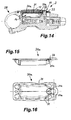
- Fig. 14
- eine Schnittdarstellung des Gebersystems mit Überströmöffnungen im umlaufenden Seitenflansch eines elastischen Balgs,
- Fig. 15
- eine Schmalseitenansicht eines Balgs mit Überströmöffnungen und
- Fig. 16
- eine Unterseitenansicht des in Fig.15 gezeigten Balgs.
- Fig. 1
- a view of a hydraulic brake system with a donor system and arranged on a brake discs brake device,
- Fig. 2
- a sectional view of the encoder system shown in Figure 1,
- Fig. 3
- a sectional view of the brake device shown in Figure 1,
- Fig. 4
- a sectional view of a sensor system in a filling and venting position with attached venting and filling tool,
- Fig. 5
- a sectional view of the encoder system in operating position,
- Fig. 6
- an enlarged view of the encoder system according to Figure 4 in the filling and venting position,
- Fig. 7
- an enlarged sectional view of the encoder system according to Figure 5 in the operating position,
- Fig. 8
- a plan view of an encoder system with open expansion tank,
- Fig. 9
- a view of a donor system with attached venting and filling tool,
- Fig. 10
- a top view of a surge tank cover,
- Fig. 11
- a side view of the lid shown in Fig.10,
- Fig. 12
- an enlarged view of a cover area with a filling and venting opening,
- Fig. 13
- a perspective view of a bellows,
- Fig. 14
- a sectional view of the encoder system with overflow openings in the circumferential side flange of an elastic bellows,
- Fig. 15
- a narrow side view of a bellows with overflow and
- Fig. 16
- a bottom view of the bellows shown in Fig15.
Eine in Fig.1 gezeigte, hydraulische Bremsanlage 1 ist insbesondere für Fahrräder, gegebenenfalls aber auch für andere Zweiräder einsetzbar. Sie weist ein Gebersystem 2 sowie eine an einer Bremsscheibe 3 angesetzte Bremsvorrichtung 4 auf. Die Bremsanlage ist mit Hydraulikflüssigkeit gefüllt, wobei das Gebersystem 2 über eine strichliniert angedeutete Hydraulikleitung 5 mit der Bremsvorrichtung 4 verbunden ist.
Das Gebersystem 2 weist einen handbetätigbaren Bremshebel 6 auf, mit dem ein in einem Zylinder 8 geführter Geberkolben 7 (vgl. Fig.2) bewegt werden kann und dabei Hydraulikflüssigkeit über die Hydraulikleitung 5 zu der Bremsvorrichtung 4 fördert. Diese Bremsvorrichtung 4 weist eine Bremszange 36 auf, die an der mit dem zu bremsenden Rad verbundenen Bremsscheibe 3 angeordnet ist. Die Bremsscheibe 3 wird beim Bremsen beidseitig mit zwei Bremsbelägen 9 beaufschlagt (Fig.3). Dazu sind in Bremszylindern 10 geführte Bremskolben 11 vorgesehen, die rückseitig mit Hydraulikflüssigkeit beaufschlagbar sind. Die Hydraulikflüssigkeit wird dabei von der Hydraulikleitung 5 über Kanäle 12 zu hinter den Bremskolben 11 befindlichen Druckkammern 13 geführt.
Das Gebersystem 2 weist einen Ausgleichsbehälter 14 für Hydraulikflüssigkeit auf, der bei unbetätigtem Bremshebel 6 mit dem Zylinder 8 und damit dem Hydraulikkreislauf verbunden ist.A shown in Figure 1,
The
The
Um das Hydrauliksystem befüllen und entlüften zu können, weist das Gebersystem 2 oberseitig eine Befüll- und Entlüftungsöffnung 15 und die Bremsvorrichtung 4 ebenfalls eine Befüll- und Entlüftungsöffnung 16 (Fig.3) auf.In order to fill and vent the hydraulic system, the
Der Bremsanlage 1 ist ein Entlüftungs- und Befüllwerkzeug 23 mit einer Kolben-Zylinderanordnung zugeordnet und die Befüll-und Entlüftungsöffnung 15 des Gebersystems 2 und vorzugsweise auch die Befüll- und Entlüftungsöffnung 16 der Bremsvorrichtung 4 sind zum lösbaren und dichten Anschließen dieses Entlüftungs- und Befüllwerkzeugs 23 ausgebildet. Die lösbare Verbindung zwischen dem Entlüftungs- und Befüllwerkzeug 23 und der Befüll- und Entlüftungsöffnung 15,16 des Gebersystems beziehungsweise der Bremsvorrichtung 4 wird dabei durch dichtendes Einstecken gebildet. Das Entlüftungs-und Befüllwerkzeug 23 hat dazu einen Anschlussstutzen 22 oder dergleichen Anschlusselement, der in die Befüll- und Entlüftungsöffnung(en) gesteckt wird.The
Insbesondere in Fig.7 ist gut erkennbar, dass die Befüll- und Entlüftungsöffnung 15 im Deckel 17 einen Einsteckabschnitt 18 aufweist, an den sich vorzugsweise fluchtend in axialer Verlängerung eine Anschlusskammer 19 im Gebergehäuse 20 anschließt. Die Anschlusskammer 19 ist topf- oder napfförmig ausgebildet und weist an ihrem Oberrand schlitzförmige, randoffene Überströmöffnungen 21 zu dem Ausgleichsbehälter 14 auf. Dadurch besteht eine Strömungsverbindung zwischen dieser Anschlusskammer 19 und dem Ausgleichsbehälter 14.
Der Einsteckabschnitt 18 der Befüll- und Entlüftungsöffnung 15 ist zur dichten Aufnahme des Anschlussstutzens 22 des Entlüftungs- und Befüllwerkzeugs 23 ausgebildet und weist dazu einen Aufnahmekonus 25 auf. Der Aufnahmekonus 25 ist zur Einsteck-Aufnahme eines als Luerkonus 24 ausgebildeten Anschlussstutzens 22 des Entlüftungs- und Befüllwerkzeugs 23 ausgebildet (Fig.6). Dadurch besteht die Möglichkeit, als Entlüftungs- und Befüllwerkzeug 23 eine handelsübliche Spritze, wie in Fig.4, 6 und 9 erkennbar, zu verwenden.
Die Einsteckverbindung mit dem Aufnahmekonus 25 und dem Anschlussstutzen 22 ist so dimensioniert, dass der Anschlussstützen 22 in Einstecklage bereichsweise in die Anschlusskammer 19 ragt, wobei er mit seinem inneren Ende noch etwas Abstand zum Grund der Anschlusskammer 19 hat, wie dies gut in Fig. 6 erkennbar ist. In dieser Einstecklage ist der Anschlussstutzen 22 des Entlüftungs- und Befüllwerkzeugs 23 sicher in dem Deckel 17 gehalten, so dass auch beim Manipulieren während eines Entlüftungs- oder Befüllvorganges ein unbeabsichtigtes Herausrutschen sicher vermieden wird.
Die Anschlusskammer 19 hat lichte Abmessungen, die größer als die des hineinragenden Teils des Anschlussstutzens 22 sind, so dass noch Platz für ein Überströmen von Hydraulikflüssigkeit durch die Überströmöffnungen 21 vorhanden ist.
Im gezeigten Ausführungsbeispiel ist die Befüll- und Entlüftungsöffnung 15 des Gebersystems 2 oberseitig an diesem vorgesehen und durchsetzt einen den Ausgleichsbehälter 14 oberseitig verschließenden Deckel 17 (Fig.4 bis 7), der durch Verschraubungen mit dem Gebergehäuse 20 verbunden ist.In particular, in Figure 7 can be clearly seen that the filling and vent
The
The plug-in connection with the receiving
The
In the illustrated embodiment, the filling and vent
Die Ausbildung der einen Zuführkanal zum Ausgleichsbehälter 14 bildenden Befüll-' und Entlüftungsöffnung 15 einerseits aufgeteilt in zwei vorzugsweise axial fluchtende Abschnitte - Einsteckabschnitt 18, Anschlusskammer 19- und andererseits angeordnet in zwei getrennt herstellbaren Teilen -Deckel 17, Gebergehäuse 17- hat fertigungstechnisch erhebliche Vorteile, weil es sich um Einzelbohrungen handelt, die durch Formstifte einfach herstellbar sind. Bei dem Zuführkanal der Befüll- und Entlüftungsöffnung 15 handelt es sich in Funktionslage um eine Stufenbohrung mit einer innenliegenden, im Durchmesser größeren Stufe, was bei einer einteiligen Ausführung formungstechnisch wegen des Hinterschnitts einen erhöhten Aufwand bedeuten würde.
Der Einsteckabschnitt 18 im Deckel 17 und die Anschlusskammer 19 im Gebergehäuse 20 sind bezüglich ihrer Längsachsen so ausgerichtet, dass sie jeweils in Entformungsrichtung des Deckels beziehungsweise des Gebergehäuses verlaufen und damit ein problemloses Entformen ermöglichen. Durch die randoffeneThe formation of a feed channel to the
The
Ausbildung der vorzugsweise schlitzförmigen Überströmöffnungen 21, die ebenfalls in Entformungsrichtung orientiert sind, sind diese ebenfalls einfach herstellbar.Formation of the preferably slot-shaped
In dem Ausführungsbeispiel ist die Befüll- und Entlüftungsöffnung 15 seitlich neben dem Ausgleichsbehälter 14 angeordnet und befindet sich in Befüll- und Entlüftungsposition gemäß Fig.6 auf der höchsten Seite neben dem Ausgleichsbehälter 14. Der Deckel 17 ist dabei so ausgebildet, dass er auch diesen, seitlich neben dem Ausgleichsbehälter 14 befindlichen Bereich des Gebergehäuses 20 übergreift.In the exemplary embodiment, the filling and venting
In Fig.8 ist gut bei oben offenem Ausgleichsbehälter 14, also ohne Deckel 17 und entferntem Balg 30 (Fig.13) erkennbar, dass die Anschlusskammer 19 der Befüll- und Entlüftungsöffnung 15 in einer seitlich in den Ausgleichsbehälter 14 ragenden Ausbuchtung 26 des Gebergehäuses 20 angeordnet ist. Die Anschlusskammer 19 ist dabei von einer Umgrenzungswand 27 umgeben, in der sich die zwei schlitzförmigen, nach oben randoffenen Überströmöffnungen 21 befinden. Die beiden Überströmöffnungen 21 sind dabei seitlich versetzt zu dem vordersten, dem Ausgleichsbehälter 14' zugewandten Bereich der Ausbuchtung 26 angeordnet. Dadurch wird erreicht, dass nach einem Befüll- oder Entlüftungsvorgang gegebenenfalls noch in der Anschlusskammer 19 befindliche Luftbläschen in der in Fig.7 gezeigten, schrägen Betriebsposition des Gebersystems 2 nicht über die Überströmöffnungen 21 in den Ausgleichsbehälter 14. gelangen können sondern im etwas höher liegenden Teil der Anschlusskammer 19 gefangen bleiben. Dazu trägt auch bei, dass die Überströmöffnungen 21 als schmale Randschlitze ausgebildet sind, wobei die Schlitzbreite zum Zurückhalten von in der Hydraulikflüssigkeit enthaltenen Luftblasen dimensioniert ist.FIG. 8 shows that the
In dem Ausgleichsbehälter 14 ist ein elastischer Balg 30 eingesetzt, der, wie in Fig.13 erkennbar, wannenförmig ausgebildet ist und an seinem Öffnungsrand eine umlaufende, als Flansch ausgebildeten Dichtung 31 aufweist. Dieser Balg 31 wird in den Ausgleichsbehälter 14 eingesetzt und füllt diesen bereichsweise aus. Die Dichtung 31 liegt auf dem Randbereich des Ausgleichsbehälters und damit auf dem Gebergehäuse 20 auf. Durch den aufgesetzten Deckel 17 erfolgt dann ein Verschließen und Abdichten sowohl des Balgs 30 als auch des Ausgleichsbehälters 14 nach außen. Der Hohlraum des Balgs 30 ist über eine Balgbelüftungsöffnung 32 (Fig. 1 und 10) durch den Deckel 17 hindurch mit der Außenatmosphäre verbunden.
Die zwischen dem Ausgleichsbehälter 14 und dem ihn oberseitig abdichtenden Deckel 17 umlaufende Dichtung 31, die durch den Seitenflansch des Balgs 30 gebildet ist, erstreckt sich auch in den Seitenbereich neben den Ausgleichsbehälter 14 und dabei zwischen den Einsteckabschnitt 18 und die Anschlusskammer 19 der Befüll- und Entlüftungsöffnung 15.
In diesem Bereich ist die Dichtung 31 mit einer Ringswulst 33 versehen, wie dies gut in Fig.6 und 13 erkennbar ist. In etwa komplementär zu dieser Ringwulst 33 weist der den Einsteckabschnitt 18 umgebende Deckelbereich eine Ringnut 34 zur dichtenden Aufnahme dieser Ringwulst 33 auf (Fig.12). Die Ringwulst 33 liegt mit ihrer Unterseite auf dem Oberrand der Anschlusskammer 19 beziehungsweise deren Begrenzungswand 27 auf (Fig.6). Die in der Begrenzungswand 27 befindlichen, randoffenen Überströmöffnungen 21 werden von der Ringwulst 33 überbrückt, wobei die erhöhte Eigenstabilität der Ringwulst 33 im Vergleich zu der flachen Ausführung der Dichtung im benachbarten Bereich auch im Überbrückungsbereich für eine gute Dichtigkeit sorgt.
Bei abgenommenem Entlüftungs- und Befüllwerkzeug 23 kann die Befüll- und Entlüftungsöffnung 15 mit einem elastischen, vorzugsweise mit einem Konus versehenen Verschlussstopfen 35 (Fig.5) verschlossen werden.In the
The between the
In this area, the
With removed ventilation and filling
Die Befüll- und Entlüftungsöffnung 15 weist vorzugsweise einen Einsteckabschnitt 18 mit einem Aufnahmekonus 25 auf, in den der mit einem dazu passenden Außenkonus versehene Verschlussstopfen 35 einsteckbar ist. Die Abdichtung erfolgt hierbei durch die Konusverbindung.The filling and venting
Der Verschlussstopfen 35 kann eine von außen zugängliche Einsteckhöhlung als Werkzeugangriffsstelle für ein Drehwerkzeug aufweisen, die bevorzugt als Innensechskant für einen Sechskantschlüssel als Drehwerkzeug ausgebildet ist.
Der Verschlussstopfen 35 kann dadurch nach dem Einsetzen des Drehwerkzeugs mit diesem etwas verdreht und dabei, unterstützt durch die Konusverbindung, herausgezogen werden.
Durch die innen liegende Werkzeugangriffsstelle kann der eingesteckte Verschlussstopfen etwa bündig mit der Außenseite des Deckels oder der Öffnung des Einsteckabschnitts 18 im Deckel 17 abschließen oder sogar etwas tiefer liegen, so dass ein unbeabsichtigtes Lösen oder Entfernen des Verschlussstopfens praktisch ausgeschlossen ist.The sealing
The closure plug 35 can thereby be slightly twisted after insertion of the rotary tool with this and thereby, supported by the cone connection, pulled out.
Through the internal tool engagement point, the inserted sealing plug can be approximately flush with the outside of the lid or the opening of the
Der Verschlussstopfen kann aus Hartkunststoffmaterial bestehen, beispielsweise aus dem gleichen Werkstoff wie der Deckel 17. Auch andere Materialien kommen in Frage, wobei nur sicher gestellt sein muss, dass das Moment zum Verdrehen des Verschlussstopfens 35 vom Drehwerkzeug übertragen werden kann.The closure plug can be made of hard plastic material, for example of the same material as the
Erwähnt sei noch, dass anstatt eines Verschlussstopfens 35 auch eine Dichtschraube vorgesehen sein kann, die in eine Gewindebohrung der Befüll- und Entlüftungsöffnung 15 einschraubbar ist, wobei die Abdichtung über die Stirnfläche erreicht wird.It should be mentioned that instead of a sealing
Bei dem in Fig. 14 im Schnitt dargestellten Gebersystem 2 sind Überströmöffnungen 21a von der Anschlusskammer zum Ausgleichsbehälter anstatt, wie vorbeschrieben, in der Begrenzungswand 27 der Anschlusskammer 19, in einem auf der Begrenzungswand aufliegenden Gegenstück angeordnet, welches im Ausführungsbeispiel die Dichtung 31 zwischen dem Deckel und dem Ausgleichsbehälter als Teil des Balgs 30a ist. Die Dichtung 31 ist dabei durch den umlaufenden Seitenflansch des elastischen Balgs 30a (Fig.15 und 16) gebildet.
Dieser Dichtungs- oder Seitenflansch erstreckt sich über den Bereich der Anschlusskammer 19 und deren Begrenzungswand 27, wobei die im Ausführungsbeispiel drei kanalförmigen Überströmöffnungen 21a (Fig.16) im Balg-Seitenflansch und damit der Dichtung 31 angeordnet sind und die Begrenzungswand 27 überdecken, also mit ihren Enden einerseits in den Ausgleichsbehälter 14 und andererseits in die Anschlusskammer 19 ragen. Durch diese Überströmöffnungen oder Überströmkanäle ist eine Strömungsverbindung zwischen der Anschlusskammer 19 und dem Ausgleichsbehälter 14 vorhanden.
Die Überströmöffnungen 21a sind als randoffene Nuten ausgebildet, die mit ihren Öffnungen der Begrenzungswand 27 zugewandt sind.
Die Dichtung 31 ist im Auflagebereich auf der Begrenzungswand 27 der Anschlusskammer 19 aufgedickt (Fig.15), so dass einerseits in diesem Bereich eine erhöhte Eigenstabilität vorhanden ist und andererseits die Platzverhältnisse für im Querschnitt ausreichend dimensionierte Überströmöffnungen 21a vorhanden sind.In the
This sealing or side flange extends over the region of the
The
The
Erwähnt sei noch, dass die wenigstens eine Überströmöffnung 21 von der Anschlusskammer 19 zum Ausgleichsbehälter 14 auch direkt im Deckel 17 vorgesehen sein kann, wenn dieser aus geeignetem Material besteht, um eine Abdichtung zur Anschlusskammer 19 zu erreichen. Auch hierbei sind die Überströmöffnungen an der entsprechenden Stelle wie bei der Dichtung 31 angeordnet. Weiterhin könnte die wenigstens eine Überströmöffnung auch als Bohrung in der Seitenwand der Anschlusskammer 19 ausgeführt sein. Bei formgebenden Verfahren wie zum Beispiel Spritzgießen sind jedoch randoffene Überströmöffnungen spritztechnisch einfacher realisierbar.It should also be mentioned that the at least one overflow opening 21 from the
Das Gebersystem 2 ist mittels einer Halterung 28 mit dem Lenker eines Zweirads verbindbar. Die Halterung 28 ist schellenartig ausgebildet und kann mit Hilfe einer Spannschraube 29 angezogen oder gelockert werden. Dadurch lässt sich das Gebersystem leicht in die passende Position einerseits für den Betrieb (Fig.5 und 7) und dementsprechend passend für eine gute Bedienbarkeit und andererseits für den Befüll- und Entlüftungsvorgang (Fig.4 und 6) entsprechend verstellen. Erwähnt sei noch, dass für den Befüll- und insbesondere den Entlüftungsvorgang das Gebersystem 2 von einer Lage mit nahezu vertikalem Entlüftungs- und Befüllwerkzeug 23 wie in Fig.4 und 6 dargestellt, bis zu einer etwa waagerechten Lage des Entlüftungs- und Befüllwerkzeugs 23 gut möglich ist.The
Zum Befüllen des Hydrauliksystems kann die das Entlüftungs-und Befüllwerkzeug 23 bildende Spritze gemäß Fig.4, 6 und 9 oberseitig auf das Gebersystem 2 aufgesteckt und dabei mit ihrem Anschlussstutzen 22 dicht in den Aufnahmekonus 25 der Befüll- und Entlüftungsöffnung 15 eingesetzt werden. Durch die vorgesehene Konusverbindung ergibt sich schon bei leichtem Eindrücken eine sichere und dichte Verbindung. Bei der Bremsvorrichtung 4 kann an die Befüll- und Entlüftungsöffnung 16 ein Behälter mit Hydraulikflüssigkeit angeschlossen werden, wobei dieser Behälter auch eine mit Hydraulikflüssigkeit gefüllte Spritze sein kann.
Vorzugsweise ist die Befüll- und Entlüftungsöffnung 16 der Bremsvorrichtung 4 ebenfalls mit einem Luer-Aufnahmekonus versehen, so dass auch hier handelsübliche Spritzen als Entlüftungs- und Befüllwerkzeug 23 angesetzt werden können.
Mit der oben bei dem Gebersystem 2 angesetzten Spritze wird die Hydraulikflüssigkeit angesaugt und strömt dann von unten in das Hydrauliksystem. Die untere, mit Hydraulikflüssigkeit gefüllte Spritze kann dabei unterstützend betätigt werden, so dass der Befüllvorgang schnell abgeschlossen werden kann.For filling the hydraulic system, the syringe forming the venting and filling
Preferably, the filling and vent
With the syringe attached above in the
Claims (26)
Applications Claiming Priority (1)
| Application Number | Priority Date | Filing Date | Title |
|---|---|---|---|
| DE102006040328A DE102006040328A1 (en) | 2006-08-29 | 2006-08-29 | Brake system with a hydraulic brake system |
Publications (3)
| Publication Number | Publication Date |
|---|---|
| EP1908659A2 true EP1908659A2 (en) | 2008-04-09 |
| EP1908659A3 EP1908659A3 (en) | 2009-03-11 |
| EP1908659B1 EP1908659B1 (en) | 2020-06-17 |
Family
ID=38989538
Family Applications (1)
| Application Number | Title | Priority Date | Filing Date |
|---|---|---|---|
| EP07016149.2A Active EP1908659B1 (en) | 2006-08-29 | 2007-08-17 | Braking system with a hydraulic braking system |
Country Status (4)
| Country | Link |
|---|---|
| US (1) | US20080060885A1 (en) |
| EP (1) | EP1908659B1 (en) |
| DE (1) | DE102006040328A1 (en) |
| TW (1) | TWI376332B (en) |
Cited By (2)
| Publication number | Priority date | Publication date | Assignee | Title |
|---|---|---|---|---|
| EP3168121A1 (en) * | 2015-11-13 | 2017-05-17 | Giant Manufacturing Co., Ltd | Hydraulic disc brake device for a bicycle |
| CN107010157A (en) * | 2015-11-13 | 2017-08-04 | 巨大机械工业股份有限公司 | Hydraulic disc brake device for bicycle |
Families Citing this family (24)
| Publication number | Priority date | Publication date | Assignee | Title |
|---|---|---|---|---|
| DE102006040327A1 (en) * | 2006-08-29 | 2008-03-06 | Gustav Magenwirth Gmbh & Co. Kg | Brake system with a hydraulic brake system |
| US7988173B2 (en) * | 2008-09-05 | 2011-08-02 | Sram, Llc | Bicycle suspension system |
| US7832531B2 (en) * | 2009-03-06 | 2010-11-16 | Shimano Inc. | Bicycle component fixing band |
| DE102009039620A1 (en) | 2009-09-01 | 2011-03-03 | Gustav Magenwirth Gmbh & Co. Kg | Encoder device for a closed hydraulic system of handlebar-guided vehicles |
| TWI382943B (en) * | 2010-08-20 | 2013-01-21 | Ashima Ltd | Hydraulic brake sealing device |
| USD641670S1 (en) | 2010-11-24 | 2011-07-19 | Hb Performance Systems, Inc. | Brake pad |
| US8943924B2 (en) | 2010-11-24 | 2015-02-03 | Hb Performance Systems, Inc. | System and method for an adjustable lever assembly |
| DE102010053009A1 (en) * | 2010-12-02 | 2012-06-06 | Jürgen Lauhoff | Actuating device for brake caliper of brake system, comprises actuating element and hydraulic cylinder, which has volume displacement element, where actuating device is connected to brake caliper by hydraulic line |
| US9550544B2 (en) | 2012-07-26 | 2017-01-24 | Shimano Inc. | Bicycle handlebar clamp assembly |
| US9199691B2 (en) * | 2012-08-03 | 2015-12-01 | Shimano Inc. | Hydraulic bicycle component kit |
| US10131339B2 (en) | 2012-08-03 | 2018-11-20 | Shimano Inc. | Hydraulic bicycle component |
| EP3038893B1 (en) * | 2013-08-27 | 2019-11-20 | Gustav Magenwirth GmbH & Co. KG | Master cylinder fitting |
| US20160059926A1 (en) * | 2014-08-29 | 2016-03-03 | Shimano Inc. | Hydraulic operating device for a bicycle |
| US9827968B2 (en) * | 2015-01-12 | 2017-11-28 | Sram, Llc | Hydraulic bicycle system |
| IT201600103768A1 (en) | 2016-10-17 | 2018-04-17 | Campagnolo Srl | Drain valve for hydraulic bicycle brake system |
| DE102016123358B4 (en) | 2016-12-02 | 2020-12-03 | Saf-Holland Gmbh | Device for actuating a brake, a brake and a method for manufacturing or upgrading a device for actuating a brake |
| CN108679202B (en) * | 2018-06-20 | 2024-06-21 | 唐泽制动器(天津)有限公司 | Brake disc assembly for transmission |
| CN110203377A (en) * | 2019-05-21 | 2019-09-06 | 成都飞机工业(集团)有限责任公司 | A kind of unmanned plane brake oil liquid exempts to be vented filling apparatus and method |
| IT201900023994A1 (en) | 2019-12-13 | 2021-06-13 | Campagnolo Srl | Hydraulic tank for bicycle |
| IT201900023988A1 (en) * | 2019-12-13 | 2021-06-13 | Campagnolo Srl | Hydraulic tank for bicycle |
| IT202100020564A1 (en) * | 2021-07-30 | 2023-01-30 | Campagnolo Srl | Diagnosis system and method of a hydraulic disc-type bicycle braking system |
| IT202100020558A1 (en) | 2021-07-30 | 2023-01-30 | Campagnolo Srl | Disc-type bicycle hydraulic brake system and related components and methods |
| DE102022121163A1 (en) * | 2022-08-22 | 2024-02-22 | Trickstuff Gmbh | Hydraulic brake arrangement for an at least partially muscle-powered bicycle |
| US12037076B1 (en) * | 2023-03-09 | 2024-07-16 | Shimano Inc. | Hydraulic reservoir and operating device of human-powered vehicle |
Citations (1)
| Publication number | Priority date | Publication date | Assignee | Title |
|---|---|---|---|---|
| US4785629A (en) | 1987-06-04 | 1988-11-22 | Ennis Iii James F | Syringe-dispensed brake fluid for filling and purging master cylinder circuit from slave |
Family Cites Families (24)
| Publication number | Priority date | Publication date | Assignee | Title |
|---|---|---|---|---|
| DE676240C (en) * | 1936-09-30 | 1939-05-30 | Rotadisk Appbau G M B H | Device for filling brakes and brake line networks with the brake fluid |
| US2524544A (en) * | 1948-03-02 | 1950-10-03 | Harry T Seawell | Hydraulic brake bleeder system |
| US4170280A (en) * | 1978-03-14 | 1979-10-09 | Parker-Hannifin Corporation | Bleeder harness for brake master cylinders |
| US4201056A (en) * | 1978-05-01 | 1980-05-06 | Kent-Moore Corporation | Brake bleeder adapter |
| US4236549A (en) * | 1978-05-12 | 1980-12-02 | Autoline Supply Company | Bleeder kit for bleeding a master cylinder |
| GB2111148B (en) * | 1981-06-09 | 1985-09-18 | Nisshin Kogyo Kk | Diaphragm assembly |
| US4788821A (en) * | 1983-11-28 | 1988-12-06 | Automotive Products, Plc | Hydraulic shift for motor vehicle transmission |
| GB8602486D0 (en) * | 1986-01-31 | 1986-03-05 | Liquid Levers Ltd | Fluid system bleeding apparatus |
| FR2654693B1 (en) * | 1989-11-22 | 1992-02-28 | Ciliento Felice | ASSORTMENT OF SPARE PARTS AND MAINTENANCE FOR A HYDRAULIC BRAKING CIRCUIT, AND METHOD FOR FILLING SUCH A CIRCUIT. |
| US5088529A (en) * | 1990-08-27 | 1992-02-18 | General Motors Corporation | Vehicle brake vacuum evacuation and brake fluid fill machine |
| AU635631B2 (en) * | 1991-01-15 | 1993-03-25 | Astra Pharmaceuticals Pty Ltd | Plastic syringe |
| US5497864A (en) * | 1995-06-20 | 1996-03-12 | Chrysler Corporation | Hydraulic brake bleeder apparatus |
| KR0120417B1 (en) * | 1995-07-19 | 1997-11-04 | Hyundai Motor Co Ltd | Oil-compensating device for brake device |
| US5950772A (en) * | 1997-08-29 | 1999-09-14 | Hayes Brake, Inc. | Bicycle brake system having a flexible disk |
| JP2002506408A (en) * | 1998-04-28 | 2002-02-26 | ロックショックス インコーポレイテッド | Concentric correction chamber and master cylinder for disc brake systems |
| US5967199A (en) * | 1998-05-13 | 1999-10-19 | General Motors Corporation | Pressurized brake bleed system |
| US6298961B1 (en) * | 2000-03-02 | 2001-10-09 | Delphi Technologies, Inc. | Reservoir cap and bleed mechanism |
| DE20015042U1 (en) * | 2000-08-30 | 2000-11-16 | Stalla & Dittrich GmbH, 71691 Freiberg | Breather device |
| JP4965058B2 (en) * | 2000-11-30 | 2012-07-04 | フレニ・ブレンボ エス・ピー・エー | Master cylinder for vehicles that can be controlled by a handlebar |
| US6871729B2 (en) * | 2001-03-02 | 2005-03-29 | Freni Brembo S.P.A. | Master cylinder for a brake or clutch of a motorcycle or bike |
| DE20108558U1 (en) * | 2001-05-22 | 2001-08-09 | Krebs, Peter, Dr., 78048 Villingen-Schwenningen | Combination needle for the peripheral nerve blocks |
| US6581905B2 (en) * | 2001-11-21 | 2003-06-24 | Tenneco Automotive Inc. | Brake bleed tool |
| CN1930038A (en) * | 2004-03-09 | 2007-03-14 | 海斯自行车集团公司 | Lever assembly and master cylinder |
| DE102006040327A1 (en) * | 2006-08-29 | 2008-03-06 | Gustav Magenwirth Gmbh & Co. Kg | Brake system with a hydraulic brake system |
-
2006
- 2006-08-29 DE DE102006040328A patent/DE102006040328A1/en not_active Withdrawn
-
2007
- 2007-08-17 EP EP07016149.2A patent/EP1908659B1/en active Active
- 2007-08-24 TW TW096131339A patent/TWI376332B/en active
- 2007-08-29 US US11/846,548 patent/US20080060885A1/en not_active Abandoned
Patent Citations (1)
| Publication number | Priority date | Publication date | Assignee | Title |
|---|---|---|---|---|
| US4785629A (en) | 1987-06-04 | 1988-11-22 | Ennis Iii James F | Syringe-dispensed brake fluid for filling and purging master cylinder circuit from slave |
Cited By (5)
| Publication number | Priority date | Publication date | Assignee | Title |
|---|---|---|---|---|
| EP3168121A1 (en) * | 2015-11-13 | 2017-05-17 | Giant Manufacturing Co., Ltd | Hydraulic disc brake device for a bicycle |
| JP2017088169A (en) * | 2015-11-13 | 2017-05-25 | 巨大機械工業股▲分▼有限公司 | Hydraulic disc brake device for bicycle |
| CN107010157A (en) * | 2015-11-13 | 2017-08-04 | 巨大机械工业股份有限公司 | Hydraulic disc brake device for bicycle |
| CN107010157B (en) * | 2015-11-13 | 2019-06-07 | 巨大机械工业股份有限公司 | Hydraulic disc brake device for bicycle |
| US10407123B2 (en) | 2015-11-13 | 2019-09-10 | Giant Manufacturing Co., Ltd. | Hydraulic disc brake device for a bicycle |
Also Published As
| Publication number | Publication date |
|---|---|
| TW200846240A (en) | 2008-12-01 |
| US20080060885A1 (en) | 2008-03-13 |
| DE102006040328A1 (en) | 2008-03-06 |
| EP1908659A3 (en) | 2009-03-11 |
| EP1908659B1 (en) | 2020-06-17 |
| TWI376332B (en) | 2012-11-11 |
Similar Documents
| Publication | Publication Date | Title |
|---|---|---|
| EP1908659B1 (en) | Braking system with a hydraulic braking system | |
| EP1894831B1 (en) | Brake device with hydraulic brake system | |
| EP1446232B1 (en) | Spray gun tank with a fixed liner | |
| EP1992395B1 (en) | Filter, particularly air filter | |
| DE19511450A1 (en) | Bypass filter unit | |
| DE3036076A1 (en) | RINSING AND SUCTION HANDPIECE | |
| DE102008002765B4 (en) | Dispenser unit and method for filling and evacuating a dispenser unit and filling insert for a dispenser unit for pasty, foamy or liquid media | |
| DE19625372A1 (en) | Process for removing puncture sealants from tires and devices for carrying out the process | |
| DE102007035386B4 (en) | venting device | |
| EP2440437A1 (en) | Connection coupling for a venting screw of a hydraulic system | |
| DE19832824A1 (en) | Issuing pump for fluids, gels etc., with issuing tube of issuing pump able to move axially in pump body | |
| DE202005021403U1 (en) | Device for feeding sealing liquid into a pneumatic tire | |
| EP2594220B1 (en) | Connection device for a cleaning device for cleaning instruments with at least one lumen to be cleaned | |
| DE20113129U1 (en) | Tire patch fluid container in a tire patch kit | |
| DE69016953T2 (en) | Compilation of replacement and maintenance parts for a liquid brake system and method for filling such a system. | |
| DE202008012804U1 (en) | Can for car tire sealant | |
| DE3322226C1 (en) | Device for the automatic flushing of milk pails | |
| EP2688781A1 (en) | Pressure medium reservoir for a hydraulic motor vehicle brake system, and filling method | |
| EP1571101B1 (en) | Device for storage and dispense of fluids | |
| CH686527A5 (en) | Pumping equipment for automotive tyres | |
| EP2006021A1 (en) | Pipette tip | |
| DE4445623C1 (en) | Hand tool for sucking out waste oil from vehicles | |
| DE1455770C (en) | Liquid tank for vehicles | |
| DE927433C (en) | Compressed air system in motor vehicles | |
| DE202021101834U1 (en) | Lid for a water treatment module |
Legal Events
| Date | Code | Title | Description |
|---|---|---|---|
| PUAI | Public reference made under article 153(3) epc to a published international application that has entered the european phase |
Free format text: ORIGINAL CODE: 0009012 |
|
| AK | Designated contracting states |
Kind code of ref document: A2 Designated state(s): AT BE BG CH CY CZ DE DK EE ES FI FR GB GR HU IE IS IT LI LT LU LV MC MT NL PL PT RO SE SI SK TR |
|
| AX | Request for extension of the european patent |
Extension state: AL BA HR MK RS |
|
| PUAL | Search report despatched |
Free format text: ORIGINAL CODE: 0009013 |
|
| AK | Designated contracting states |
Kind code of ref document: A3 Designated state(s): AT BE BG CH CY CZ DE DK EE ES FI FR GB GR HU IE IS IT LI LT LU LV MC MT NL PL PT RO SE SI SK TR |
|
| AX | Request for extension of the european patent |
Extension state: AL BA HR MK RS |
|
| RIC1 | Information provided on ipc code assigned before grant |
Ipc: B60T 17/22 20060101ALI20090204BHEP Ipc: B62L 3/02 20060101ALI20090204BHEP Ipc: B60T 11/30 20060101ALI20090204BHEP Ipc: B60T 11/22 20060101AFI20080229BHEP |
|
| 17Q | First examination report despatched |
Effective date: 20090925 |
|
| 17P | Request for examination filed |
Effective date: 20090827 |
|
| AKX | Designation fees paid |
Designated state(s): AT BE BG CH CY CZ DE DK EE ES FI FR GB GR HU IE IS IT LI LT LU LV MC MT NL PL PT RO SE SI SK TR |
|
| STAA | Information on the status of an ep patent application or granted ep patent |
Free format text: STATUS: EXAMINATION IS IN PROGRESS |
|
| GRAP | Despatch of communication of intention to grant a patent |
Free format text: ORIGINAL CODE: EPIDOSNIGR1 |
|
| STAA | Information on the status of an ep patent application or granted ep patent |
Free format text: STATUS: GRANT OF PATENT IS INTENDED |
|
| INTG | Intention to grant announced |
Effective date: 20200303 |
|
| GRAS | Grant fee paid |
Free format text: ORIGINAL CODE: EPIDOSNIGR3 |
|
| GRAA | (expected) grant |
Free format text: ORIGINAL CODE: 0009210 |
|
| STAA | Information on the status of an ep patent application or granted ep patent |
Free format text: STATUS: THE PATENT HAS BEEN GRANTED |
|
| AK | Designated contracting states |
Kind code of ref document: B1 Designated state(s): AT BE BG CH CY CZ DE DK EE ES FI FR GB GR HU IE IS IT LI LT LU LV MC MT NL PL PT RO SE SI SK TR |
|
| REG | Reference to a national code |
Ref country code: GB Ref legal event code: FG4D Free format text: NOT ENGLISH |
|
| REG | Reference to a national code |
Ref country code: CH Ref legal event code: EP |
|
| REG | Reference to a national code |
Ref country code: DE Ref legal event code: R096 Ref document number: 502007016889 Country of ref document: DE |
|
| REG | Reference to a national code |
Ref country code: IE Ref legal event code: FG4D Free format text: LANGUAGE OF EP DOCUMENT: GERMAN |
|
| REG | Reference to a national code |
Ref country code: AT Ref legal event code: REF Ref document number: 1280944 Country of ref document: AT Kind code of ref document: T Effective date: 20200715 |
|
| PG25 | Lapsed in a contracting state [announced via postgrant information from national office to epo] |
Ref country code: LT Free format text: LAPSE BECAUSE OF FAILURE TO SUBMIT A TRANSLATION OF THE DESCRIPTION OR TO PAY THE FEE WITHIN THE PRESCRIBED TIME-LIMIT Effective date: 20200617 Ref country code: SE Free format text: LAPSE BECAUSE OF FAILURE TO SUBMIT A TRANSLATION OF THE DESCRIPTION OR TO PAY THE FEE WITHIN THE PRESCRIBED TIME-LIMIT Effective date: 20200617 Ref country code: FI Free format text: LAPSE BECAUSE OF FAILURE TO SUBMIT A TRANSLATION OF THE DESCRIPTION OR TO PAY THE FEE WITHIN THE PRESCRIBED TIME-LIMIT Effective date: 20200617 Ref country code: GR Free format text: LAPSE BECAUSE OF FAILURE TO SUBMIT A TRANSLATION OF THE DESCRIPTION OR TO PAY THE FEE WITHIN THE PRESCRIBED TIME-LIMIT Effective date: 20200918 |
|
| REG | Reference to a national code |
Ref country code: LT Ref legal event code: MG4D |
|
| REG | Reference to a national code |
Ref country code: NL Ref legal event code: MP Effective date: 20200617 |
|
| PG25 | Lapsed in a contracting state [announced via postgrant information from national office to epo] |
Ref country code: LV Free format text: LAPSE BECAUSE OF FAILURE TO SUBMIT A TRANSLATION OF THE DESCRIPTION OR TO PAY THE FEE WITHIN THE PRESCRIBED TIME-LIMIT Effective date: 20200617 Ref country code: BG Free format text: LAPSE BECAUSE OF FAILURE TO SUBMIT A TRANSLATION OF THE DESCRIPTION OR TO PAY THE FEE WITHIN THE PRESCRIBED TIME-LIMIT Effective date: 20200917 |
|
| PG25 | Lapsed in a contracting state [announced via postgrant information from national office to epo] |
Ref country code: NL Free format text: LAPSE BECAUSE OF FAILURE TO SUBMIT A TRANSLATION OF THE DESCRIPTION OR TO PAY THE FEE WITHIN THE PRESCRIBED TIME-LIMIT Effective date: 20200617 |
|
| PG25 | Lapsed in a contracting state [announced via postgrant information from national office to epo] |
Ref country code: PT Free format text: LAPSE BECAUSE OF FAILURE TO SUBMIT A TRANSLATION OF THE DESCRIPTION OR TO PAY THE FEE WITHIN THE PRESCRIBED TIME-LIMIT Effective date: 20201019 Ref country code: CZ Free format text: LAPSE BECAUSE OF FAILURE TO SUBMIT A TRANSLATION OF THE DESCRIPTION OR TO PAY THE FEE WITHIN THE PRESCRIBED TIME-LIMIT Effective date: 20200617 Ref country code: RO Free format text: LAPSE BECAUSE OF FAILURE TO SUBMIT A TRANSLATION OF THE DESCRIPTION OR TO PAY THE FEE WITHIN THE PRESCRIBED TIME-LIMIT Effective date: 20200617 Ref country code: EE Free format text: LAPSE BECAUSE OF FAILURE TO SUBMIT A TRANSLATION OF THE DESCRIPTION OR TO PAY THE FEE WITHIN THE PRESCRIBED TIME-LIMIT Effective date: 20200617 Ref country code: ES Free format text: LAPSE BECAUSE OF FAILURE TO SUBMIT A TRANSLATION OF THE DESCRIPTION OR TO PAY THE FEE WITHIN THE PRESCRIBED TIME-LIMIT Effective date: 20200617 |
|
| PG25 | Lapsed in a contracting state [announced via postgrant information from national office to epo] |
Ref country code: IS Free format text: LAPSE BECAUSE OF FAILURE TO SUBMIT A TRANSLATION OF THE DESCRIPTION OR TO PAY THE FEE WITHIN THE PRESCRIBED TIME-LIMIT Effective date: 20201017 Ref country code: PL Free format text: LAPSE BECAUSE OF FAILURE TO SUBMIT A TRANSLATION OF THE DESCRIPTION OR TO PAY THE FEE WITHIN THE PRESCRIBED TIME-LIMIT Effective date: 20200617 Ref country code: SK Free format text: LAPSE BECAUSE OF FAILURE TO SUBMIT A TRANSLATION OF THE DESCRIPTION OR TO PAY THE FEE WITHIN THE PRESCRIBED TIME-LIMIT Effective date: 20200617 |
|
| REG | Reference to a national code |
Ref country code: DE Ref legal event code: R097 Ref document number: 502007016889 Country of ref document: DE |
|
| PG25 | Lapsed in a contracting state [announced via postgrant information from national office to epo] |
Ref country code: MC Free format text: LAPSE BECAUSE OF FAILURE TO SUBMIT A TRANSLATION OF THE DESCRIPTION OR TO PAY THE FEE WITHIN THE PRESCRIBED TIME-LIMIT Effective date: 20200617 |
|
| REG | Reference to a national code |
Ref country code: CH Ref legal event code: PL |
|
| PLBE | No opposition filed within time limit |
Free format text: ORIGINAL CODE: 0009261 |
|
| STAA | Information on the status of an ep patent application or granted ep patent |
Free format text: STATUS: NO OPPOSITION FILED WITHIN TIME LIMIT |
|
| PG25 | Lapsed in a contracting state [announced via postgrant information from national office to epo] |
Ref country code: LI Free format text: LAPSE BECAUSE OF NON-PAYMENT OF DUE FEES Effective date: 20200831 Ref country code: DK Free format text: LAPSE BECAUSE OF FAILURE TO SUBMIT A TRANSLATION OF THE DESCRIPTION OR TO PAY THE FEE WITHIN THE PRESCRIBED TIME-LIMIT Effective date: 20200617 Ref country code: CH Free format text: LAPSE BECAUSE OF NON-PAYMENT OF DUE FEES Effective date: 20200831 Ref country code: LU Free format text: LAPSE BECAUSE OF NON-PAYMENT OF DUE FEES Effective date: 20200817 |
|
| 26N | No opposition filed |
Effective date: 20210318 |
|
| REG | Reference to a national code |
Ref country code: BE Ref legal event code: MM Effective date: 20200831 |
|
| PG25 | Lapsed in a contracting state [announced via postgrant information from national office to epo] |
Ref country code: SI Free format text: LAPSE BECAUSE OF FAILURE TO SUBMIT A TRANSLATION OF THE DESCRIPTION OR TO PAY THE FEE WITHIN THE PRESCRIBED TIME-LIMIT Effective date: 20200617 |
|
| PG25 | Lapsed in a contracting state [announced via postgrant information from national office to epo] |
Ref country code: BE Free format text: LAPSE BECAUSE OF NON-PAYMENT OF DUE FEES Effective date: 20200831 Ref country code: IE Free format text: LAPSE BECAUSE OF NON-PAYMENT OF DUE FEES Effective date: 20200817 |
|
| PG25 | Lapsed in a contracting state [announced via postgrant information from national office to epo] |
Ref country code: TR Free format text: LAPSE BECAUSE OF FAILURE TO SUBMIT A TRANSLATION OF THE DESCRIPTION OR TO PAY THE FEE WITHIN THE PRESCRIBED TIME-LIMIT Effective date: 20200617 Ref country code: MT Free format text: LAPSE BECAUSE OF FAILURE TO SUBMIT A TRANSLATION OF THE DESCRIPTION OR TO PAY THE FEE WITHIN THE PRESCRIBED TIME-LIMIT Effective date: 20200617 Ref country code: CY Free format text: LAPSE BECAUSE OF FAILURE TO SUBMIT A TRANSLATION OF THE DESCRIPTION OR TO PAY THE FEE WITHIN THE PRESCRIBED TIME-LIMIT Effective date: 20200617 |
|
| PGFP | Annual fee paid to national office [announced via postgrant information from national office to epo] |
Ref country code: DE Payment date: 20240819 Year of fee payment: 18 |
|
| PGFP | Annual fee paid to national office [announced via postgrant information from national office to epo] |
Ref country code: GB Payment date: 20240821 Year of fee payment: 18 |
|
| PGFP | Annual fee paid to national office [announced via postgrant information from national office to epo] |
Ref country code: FR Payment date: 20240823 Year of fee payment: 18 |
|
| PGFP | Annual fee paid to national office [announced via postgrant information from national office to epo] |
Ref country code: AT Payment date: 20240823 Year of fee payment: 18 |
|
| PGFP | Annual fee paid to national office [announced via postgrant information from national office to epo] |
Ref country code: IT Payment date: 20240827 Year of fee payment: 18 |
|
| REG | Reference to a national code |
Ref country code: DE Ref legal event code: R119 Ref document number: 502007016889 Country of ref document: DE |
|
| PG25 | Lapsed in a contracting state [announced via postgrant information from national office to epo] |
Ref country code: AT Free format text: LAPSE BECAUSE OF NON-PAYMENT OF DUE FEES Effective date: 20250817 |
|
| REG | Reference to a national code |
Ref country code: AT Ref legal event code: MM01 Ref document number: 1280944 Country of ref document: AT Kind code of ref document: T Effective date: 20250817 |