EP1908374B1 - Synchron-Bürostuhl - Google Patents
Synchron-Bürostuhl Download PDFInfo
- Publication number
- EP1908374B1 EP1908374B1 EP07405286A EP07405286A EP1908374B1 EP 1908374 B1 EP1908374 B1 EP 1908374B1 EP 07405286 A EP07405286 A EP 07405286A EP 07405286 A EP07405286 A EP 07405286A EP 1908374 B1 EP1908374 B1 EP 1908374B1
- Authority
- EP
- European Patent Office
- Prior art keywords
- support
- synchronised
- seat support
- office chair
- stop
- Prior art date
- Legal status (The legal status is an assumption and is not a legal conclusion. Google has not performed a legal analysis and makes no representation as to the accuracy of the status listed.)
- Active
Links
- 230000001360 synchronised effect Effects 0.000 title claims description 75
- 230000007246 mechanism Effects 0.000 claims description 16
- 238000005096 rolling process Methods 0.000 claims description 7
- 239000003365 glass fiber Substances 0.000 claims description 4
- 239000002131 composite material Substances 0.000 claims description 3
- 230000004913 activation Effects 0.000 claims description 2
- 238000006073 displacement reaction Methods 0.000 claims description 2
- 230000000694 effects Effects 0.000 description 5
- 230000008859 change Effects 0.000 description 2
- 238000005352 clarification Methods 0.000 description 2
- 239000000463 material Substances 0.000 description 2
- 229910000831 Steel Inorganic materials 0.000 description 1
- 230000009849 deactivation Effects 0.000 description 1
- 239000011521 glass Substances 0.000 description 1
- 210000003127 knee Anatomy 0.000 description 1
- 230000036316 preload Effects 0.000 description 1
- 239000010959 steel Substances 0.000 description 1
Images


Classifications
-
- A—HUMAN NECESSITIES
- A47—FURNITURE; DOMESTIC ARTICLES OR APPLIANCES; COFFEE MILLS; SPICE MILLS; SUCTION CLEANERS IN GENERAL
- A47C—CHAIRS; SOFAS; BEDS
- A47C1/00—Chairs adapted for special purposes
- A47C1/02—Reclining or easy chairs
- A47C1/031—Reclining or easy chairs having coupled concurrently adjustable supporting parts
- A47C1/032—Reclining or easy chairs having coupled concurrently adjustable supporting parts the parts being movably-coupled seat and back-rest
- A47C1/03205—Reclining or easy chairs having coupled concurrently adjustable supporting parts the parts being movably-coupled seat and back-rest having adjustable and lockable inclination
- A47C1/03238—Reclining or easy chairs having coupled concurrently adjustable supporting parts the parts being movably-coupled seat and back-rest having adjustable and lockable inclination by means of peg-and-notch or pawl-and-ratchet mechanism
-
- A—HUMAN NECESSITIES
- A47—FURNITURE; DOMESTIC ARTICLES OR APPLIANCES; COFFEE MILLS; SPICE MILLS; SUCTION CLEANERS IN GENERAL
- A47C—CHAIRS; SOFAS; BEDS
- A47C1/00—Chairs adapted for special purposes
- A47C1/02—Reclining or easy chairs
- A47C1/031—Reclining or easy chairs having coupled concurrently adjustable supporting parts
- A47C1/032—Reclining or easy chairs having coupled concurrently adjustable supporting parts the parts being movably-coupled seat and back-rest
- A47C1/03255—Reclining or easy chairs having coupled concurrently adjustable supporting parts the parts being movably-coupled seat and back-rest with a central column, e.g. rocking office chairs
-
- A—HUMAN NECESSITIES
- A47—FURNITURE; DOMESTIC ARTICLES OR APPLIANCES; COFFEE MILLS; SPICE MILLS; SUCTION CLEANERS IN GENERAL
- A47C—CHAIRS; SOFAS; BEDS
- A47C1/00—Chairs adapted for special purposes
- A47C1/02—Reclining or easy chairs
- A47C1/031—Reclining or easy chairs having coupled concurrently adjustable supporting parts
- A47C1/032—Reclining or easy chairs having coupled concurrently adjustable supporting parts the parts being movably-coupled seat and back-rest
- A47C1/03261—Reclining or easy chairs having coupled concurrently adjustable supporting parts the parts being movably-coupled seat and back-rest characterised by elastic means
- A47C1/03277—Reclining or easy chairs having coupled concurrently adjustable supporting parts the parts being movably-coupled seat and back-rest characterised by elastic means with bar or leaf springs
-
- A—HUMAN NECESSITIES
- A47—FURNITURE; DOMESTIC ARTICLES OR APPLIANCES; COFFEE MILLS; SPICE MILLS; SUCTION CLEANERS IN GENERAL
- A47C—CHAIRS; SOFAS; BEDS
- A47C1/00—Chairs adapted for special purposes
- A47C1/02—Reclining or easy chairs
- A47C1/031—Reclining or easy chairs having coupled concurrently adjustable supporting parts
- A47C1/032—Reclining or easy chairs having coupled concurrently adjustable supporting parts the parts being movably-coupled seat and back-rest
- A47C1/03294—Reclining or easy chairs having coupled concurrently adjustable supporting parts the parts being movably-coupled seat and back-rest slidingly movable in the base frame, e.g. by rollers
Definitions
- the invention relates to a synchronous office chair according to claim 1.
- a synchronous office chair is commonly referred to a chair in which a seat part and a backrest part can perform coupled movements.
- such an office chair can be designed so that the inclination of the backrest part is coupled with a smaller inclination of the seat surface part.
- the present invention relates to a synchronous office chair having substantially three main parts cooperating to provide synchronous movement of the synchronous office chair.
- These three main parts are arranged on a support column and comprise a support fixedly connected to the support column, a seat support hinged to the support on a tilting axis and a back part which is coupled to the support and the seat support.
- the tilting axis is located under the front area of the seat, ie approximately in the knee area of the seated person.
- the object of the invention is to provide an improved synchronous office chair, in which the undesirable "pull-out" effect is largely avoided.
- the synchronous movement i. the positively driven relative movement of seat support and back part is achieved by the leadership of the roller bearings in the curved paths.
- the disclosed arrangement of the roller bearings and the cam tracks causes the instantaneous pivot point of the tilting movement of the back part about the virtual axis to be essentially always approximately the same distance above the rear central part of the seat carrier.
- the improved synchronous mechanism can also be well combined with a device for slowing down the synchronous movement - namely in the form of a bias voltage.
- the goal is to achieve an adjustable cushioning of the seat support and the back part, which is optimally suitable and adjustable for very light as well as for very heavy people, and also has a very high reliability and durability.
- leaf springs made of a glass fiber plastic composite material with unidirectionally directed glass fibers provide the necessary strength values and in particular the desired service life.
- Other materials, such as steel springs and the like, on the other hand, tend to break fatigue much more quickly and, moreover, can not usually be used for the entire range of applications from very light to very heavy Persons are suitably dimensioned.
- the improved synchronous mechanism can also be combined well with a device for limiting the synchronous movement - here in the form of a tilt stop.
- the user of the synchronous office chair according to the invention should be able to adjust and change the maximum inclination of the back part or of the seat support in a simple manner.
- a toothed segment on the support and a gear with a stop disc and a grid lever in a tilting mechanism holder on the seat support and an actuator for actuating the grid lever can be achieved here the desired simple and reliable mechanical structure.
- the mentioned elements for realizing the inclination stop ultimately cause the gear that runs on the toothed segment - depending on the setting of the inclination stop - can only depart a certain way on the whole available path on the sector gear.
- the entire available path on the toothed segment can be utilized.
- the user can therefore, for example by means of a push button on a cable, solve the grid lever of the stop disc and tilt the synchronous office chair in any tilt position (within the entire possible range of synchronous movement) to the rear to pick a new stop position.
- a push button on a cable solves the grid lever of the stop disc and tilt the synchronous office chair in any tilt position (within the entire possible range of synchronous movement) to the rear to pick a new stop position.
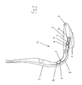
- FIG. 1 shows a schematic side view of a synchronous office chair with a support 1, a seat support 2 and a back part 3 at a Weglichn Trent of 0 °.
- Two of these three "main parts”, namely the seat support 2 and the back part 3 are movable in such a way that a synchronous movement is created.
- the FIG. 1 (as well as the FIG. 2 ) serve mainly to clarify the basic arrangement of the main parts, the carrier 1, the seat support 2 and the back part 3 for the purpose of representing their shape in the Figures 3-5 also shown in spatial representations.
- the carrier 1 is fixedly connected to a support column (not shown).
- the support column can be mounted in a manner customary for office chairs on an office chair foot part.
- the seat support 2 is articulated on a tilting axis 4.
- the seat support 2 has a rearwardly and upwardly toward the back part 3 extending horn 5.
- Seat support 2 and horn 5 are firmly connected.
- the back part 3 has a back bracket 6 extending downwards and toward the direction of the seat support 2.
- Back part 3 and back bar 6 are also firmly connected.
- the back bar 6 of the back part 3 engages in a space between the carrier 1 and the seat support 2, and the horn 5 of the seat support 2 engages in the back strap 6 a.
- the back yoke 6 has a first curved track 7, a second curved track 8, and a third curved track 9.
- the curved paths 7, 8, 9 are all approximately circular-arc-like and concave from the point of view of a viewer standing in front of and above the synchronous office chair.
- the second and third curved paths 8, 9 are brought together so closely from a lateral view (as shown here) that there is an overlap.
- a first roller bearing 10 is mounted, which engages in the first curved path 7 of the back yoke 6 and is guided in the synchronous movement of the office chair in the first curved path 7.
- a second roller bearing 11 is mounted, which engages in the second curved path 8 of the back yoke 6 and is guided in the synchronous movement of the office chair in the second curved path 8.
- a third roller bearing 12 is mounted, which engages in the third curved path 9 of the back bracket 6 and is guided in the synchronous movement of the office chair in the third curved path 9.
- the seat support 2 with the horn 5 makes a first tilting movement about the tilting axis 4.
- the back part 3 with the back yoke 6 makes a second tilting movement about a virtual axis 13 which is about two to three times as large as the first tilting movement.
- the back part 3 with the back bar 6 is still a translational movement down and forward.
- FIG. 2 shows a schematic side view of the synchronous office chair according Fig. 1 at a seat post inclination of 11 °.
- the back part 3 with the back bar 6 has made a sliding movement downwards and forwards and simultaneously also a rotational movement about the virtual axis 13.
- the instantaneous position of the virtual axis 13 is also shown here. It should be noted that the distance of the virtual axis 13 to the upper edge of the seat support 2 has barely changed.
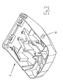
- FIG. 3 shows for clarity a spatial view of the carrier according to Fig. 1 , in the view from above and behind. Particularly clearly visible here is the third roller bearing 12th
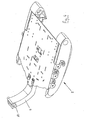
- FIG. 4 shows for clarity a spatial view of the seat support according to Fig. 1 , in the view from above and in front.
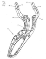
- FIG. 5 shows for clarity a spatial view of the back according to Fig. 1 , in the view from the front and above. Particularly clearly visible here are first, second and third curved path 7,8,9.
- FIG. 6 shows a schematic side view of the carrier 1 and the seat support 2 with the basic arrangement of the elements of the bias.
- the most important elements of the prestressing comprise at least one leaf spring 20, a support device 21, a support 22, a support surface 23 and a positioning device 24 for the support 22 on the support surface 23.
- the at least one leaf spring 20 is used to generate a biasing force for the bias and is fixed to a first leaf spring end 25 in the region of the tilting axis 4 on the carrier 1.
- the second (opposite) leaf spring end 26 is arranged vertically movable and resilient in the area below the rear middle part of the seat support 2.
- the seat support 2 is supported by means of the support means 21 attached thereto at the rear central part of the seat support 2 rolling or sliding on the / the leaf spring (s) or can be supported thereon.
- the at least one leaf spring 20 in turn is supported on the support surface 23 rolling or slidingly displaceable support 22.
- the positioning device 24 for the support 22 on the support surface 23 may be configured in various ways, but advantageously it is adjustable via a bevel gear 27 whose drive axis is arranged coaxially to the tilting axis 4.
- the at least one leaf spring 20 preferably consists of a glass fiber-plastic composite material with unidirectionally directed glass fibers.
- the strength values and the reliability of these (today common) materials are so good that can be realized with the disclosed leaf spring design preloads in a range of forces that can cover the entire range of application of very light to very heavy people.
- FIG. 7 shows for the sake of further clarification an exemption of the elements of the bias. Shown here is a bias with two parallel leaf springs 20, wherein the support means for the leaf springs 20 are formed here as a substantially cylindrical, slidable supports 22, and wherein the two supports 22 together by means of a shaft 28 and a threaded spindle 29 via the bevel gear 27th on the support surface 23 (see Fig. 6 ) can be slidably positioned.
- rolling supports could also be provided.
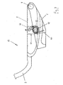
- FIG. 8 shows a spatial view of the carrier 1 with the elements of the bias voltage.
- plastic inserts 30 in which the leaf springs 20 at the first leaf spring ends 25th be held and fixed.
- the threaded spindle 29 via the bevel gear 27 is rotatable. Since the threaded spindle 29 is guided in a threaded hole of the shaft 28, by rotation on the crank 31, the position of the supports 22 on the bearing surface - and thus the biasing force for the bias - can be adjusted.
- FIG. 9 shows a schematic side view of the carrier 1 and the seat support 2 with the basic arrangement of the elements of the inclination stop.
- the most important elements of the inclination stop include a toothed segment 40 attached to the carrier 1 and a tilting mechanism holder 41 attached to the seat carrier 2.
- the tilting mechanism holder 41 in turn essentially contains a toothed wheel 42, a stop disc 43 and a ratchet lever 44 Tilting axis 4 moves the gear 42 on the sector gear 40 a certain way - here, of course, a circular arc segment - from.
- this path, or the circular arc segment is approximately 11 ° (angle degree) at a maximum when the inclination stop is fully released (deactivated).
- the gear 42 (in the present geometric conditions and because of the relatively narrow arc segment) when rolling on the sector gear 40 undergoes no complete revolution, it does not need to be provided with a toothing over the entire circumference.
- the activation / deactivation of the inclination stop is carried out via an actuation of the grid lever 44, which can be done for example by means of a push button via a cable.
- Other actuation mechanisms for example via linkage, are well known to those skilled in the art and of course, of course, may also be used.
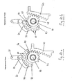
- FIG. 10a shows a schematic representation of the elements of the inclination stop in the 0 ° position (the maximum inclination of the seat support 2 about the tilting axis 4 is here 0 °).
- the remaining parts of the synchronous office chair are omitted in this drawing.
- the inclination of the seat support 2 (not shown here) has a tilt angle of 0 ° (inclination about the tilting axis 4).
- the tilt stop is activated because the locking cam 50 of the grid lever 44 engages in the ratchet teeth 47 of the stop plate 43 and therefore prevents rotation of the stop plate 43. If a person sat down on the synchronous office chair, the gear 42 would go down in a counter-clockwise rotation on the toothed segment 40 when the tilt stop was not activated. This movement is blocked here but because of the abutting gear stop 45 and disc stop 46. The synchronous movement of the office chair is thus completely prevented here.
- the locking cam 50 of the grid lever 44 does not engage in the ratchet teeth 47 of the stop disc 43.
- the user of the synchronous office chair can recline with the tilt stop disabled, for example, up to a tilt of the seat support 2 by a tilt angle of 6 ° (inclination about the tilt axis 4), whereby the gear 42 and the stop plate 43 in the FIG. 10b reach shown position. If the user of the synchronous office chair decides that this position should be the maximum tilt position desired by him, he can in turn activate the inclination stop in this position, ie he can let snap the grid lever 44 with the locking cam 50 in this position again in the grid teeth 47 of the stop plate. This is so in the FIG. 10b shown.
- the Fig. 10b thus, finally shows a schematic representation of the elements of the inclination stop in the 6 ° position (the maximum inclination of the seat support 2 about the tilting axis 4 is here 6 °).
- the tilt stop is activated because the locking cam 50 of the grid lever 44 engages in the ratchet teeth 47 of the stop plate 43 and therefore prevents rotation of the stop plate 43.
- here is the tilting movement of the seat support 2 in the inclination range between 0 ° and 6 ° possible because the gear 42 and the stop plate 43 are at least partially mutually rotatable on the axis 48 are arranged.
- the disclosed inclination stop acts as a means for limiting the synchronous movement, ie the synchronous movement can be limited in one of the selectable rotational position of the stop disc 43 corresponding inclination position of the seat support 2 and the back part 3.
- the geometry and the design of the inventive tilt stop need not necessarily correspond exactly to the embodiment shown.
- the gear 42 with gear stopper 45 and the stopper plate 43 with the disc stopper 46 must not be made in one piece and neither the gear 42 nor the stopper plate 43 need only be provided on a part of its circumference with a toothing.
- both the device for the tilt stop as well as the device for the bias voltage are particularly suitable to be used in an office chair with a synchronous movement designed according to the invention.
- the inclination stop allows an optional and particularly easy-to-use limitation of the synchronous movement with simple means, while the bias is mainly due to the very large adjustment range, but certainly also because of the basic simplicity, well suited.
- the seat support 2 and the horn 5 are firmly connected together, as well as the back part 3 and the back bar 6.
- the corresponding parts it is structurally readily possible to make the corresponding parts either assemblable or in one piece.
Landscapes
- Health & Medical Sciences (AREA)
- Dentistry (AREA)
- General Health & Medical Sciences (AREA)
- Chairs Characterized By Structure (AREA)
- Chairs For Special Purposes, Such As Reclining Chairs (AREA)
- Exchange Systems With Centralized Control (AREA)
- Liquid Crystal Substances (AREA)
- Chair Legs, Seat Parts, And Backrests (AREA)
- Organic Low-Molecular-Weight Compounds And Preparation Thereof (AREA)
Applications Claiming Priority (1)
| Application Number | Priority Date | Filing Date | Title |
|---|---|---|---|
| CH16002006 | 2006-10-06 |
Publications (2)
| Publication Number | Publication Date |
|---|---|
| EP1908374A1 EP1908374A1 (de) | 2008-04-09 |
| EP1908374B1 true EP1908374B1 (de) | 2009-02-11 |
Family
ID=38050193
Family Applications (1)
| Application Number | Title | Priority Date | Filing Date |
|---|---|---|---|
| EP07405286A Active EP1908374B1 (de) | 2006-10-06 | 2007-09-26 | Synchron-Bürostuhl |
Country Status (8)
| Country | Link |
|---|---|
| US (1) | US7513569B2 (pt) |
| EP (1) | EP1908374B1 (pt) |
| JP (1) | JP2008093447A (pt) |
| AT (1) | ATE422315T1 (pt) |
| BR (1) | BRPI0704231B8 (pt) |
| DE (1) | DE502007000434D1 (pt) |
| ES (1) | ES2322301T3 (pt) |
| PT (1) | PT1908374E (pt) |
Families Citing this family (23)
| Publication number | Priority date | Publication date | Assignee | Title |
|---|---|---|---|---|
| AR057387A1 (es) * | 2005-06-20 | 2007-12-05 | Humanscale Corp | Aparato de asiento con movimiento reclinable |
| GB0708053D0 (en) | 2007-04-26 | 2007-06-06 | Leuven | Adjustable furniture |
| DE202008006179U1 (de) * | 2008-05-06 | 2008-07-17 | Design Ballendat Gmbh | Stuhl mit schwenkbarer Rückenlehne |
| US20100141002A1 (en) * | 2008-06-04 | 2010-06-10 | Kurrasch Andrew J | Biasing mechanism |
| DE102009050903B4 (de) * | 2009-10-27 | 2014-02-13 | Siemens Aktiengesellschaft | Fahrzeugsitz |
| DE102009052111B4 (de) | 2009-11-05 | 2012-05-16 | Johnson Controls Gmbh | Sitzkissenneigungseinstellung |
| GB201014953D0 (en) | 2010-09-08 | 2010-10-20 | Birkbeck Hilary R | Slide chair action |
| GB201015414D0 (en) | 2010-09-15 | 2010-10-27 | Birkbeck Hilary R | Link chair action |
| EP2739183B1 (en) * | 2011-08-04 | 2017-10-04 | Cramer LLC | Ergonomic seating assemblies and methods |
| US9504326B1 (en) | 2012-04-10 | 2016-11-29 | Humanscale Corporation | Reclining chair |
| USD697726S1 (en) | 2012-09-20 | 2014-01-21 | Steelcase Inc. | Chair |
| US11304528B2 (en) | 2012-09-20 | 2022-04-19 | Steelcase Inc. | Chair assembly with upholstery covering |
| WO2014163581A1 (en) * | 2013-04-05 | 2014-10-09 | Singapore Technologies Aerospace Ltd | Seat structure for a passenger seat and passenger seat |
| EP2981190B1 (en) * | 2013-04-05 | 2021-11-17 | St Engineering Aerospace Ltd. | Passenger seat for an aircraft |
| US11596235B2 (en) | 2015-02-11 | 2023-03-07 | Aaron DeJule | Apparatus with weight responsive changeable adjusting characteristics |
| JP6840675B2 (ja) | 2015-03-14 | 2021-03-10 | ハーマン、ミラー、インコーポレイテッドHerman Miller Incorporated | 椅子用の機械的組立体及びその機械的組立体を有する椅子 |
| DE102017105398A1 (de) | 2016-03-14 | 2017-09-14 | Burkhard Schmitz | Stuhl |
| DE102016104638A1 (de) | 2016-03-14 | 2017-09-14 | Burkhard Schmitz | Stuhl |
| JP7107902B2 (ja) * | 2019-02-26 | 2022-07-27 | トヨタ自動車株式会社 | 車両用シート |
| EP3702209B1 (en) | 2019-02-26 | 2023-06-21 | Toyota Jidosha Kabushiki Kaisha | Vehicle seat |
| US12089741B2 (en) * | 2019-06-17 | 2024-09-17 | Quali Co., Ltd. | Tiltable chair |
| NL2026485B1 (en) | 2020-09-16 | 2022-05-16 | Npk Design B V | Adjustable chair |
| US11812870B2 (en) | 2021-02-10 | 2023-11-14 | Steelcase Inc. | Body support structure |
Family Cites Families (19)
| Publication number | Priority date | Publication date | Assignee | Title |
|---|---|---|---|---|
| FR1596508A (pt) * | 1968-07-18 | 1970-06-22 | ||
| BR8203375A (pt) * | 1981-06-15 | 1983-05-31 | Budd Co | Folha de mola para suspensao de estruturas recipocas e processo de sua fabricacao |
| JPH0436675Y2 (pt) * | 1986-04-03 | 1992-08-28 | ||
| NL8601457A (nl) * | 1986-06-05 | 1988-01-04 | Huka Bv Developments | Rolstoel met kantelbaar zitgedeelte. |
| US5058954A (en) * | 1988-07-07 | 1991-10-22 | Kan Chee Lee | Body contour support structure for travelers and audiences |
| JPH0520199Y2 (pt) * | 1988-11-30 | 1993-05-26 | ||
| JPH0779742B2 (ja) * | 1989-07-27 | 1995-08-30 | 株式会社イトーキクレビオ | 椅子の傾動装置 |
| DE4135948C2 (de) * | 1991-10-31 | 1993-12-23 | Rolf Voelkle | Stuhl, insbesondere Bürodrehstuhl |
| EP0726723B1 (en) * | 1993-11-01 | 1998-11-25 | Labofa A/S | A working chair with synchronous seat and back adjustment |
| US5558399A (en) * | 1994-09-13 | 1996-09-24 | Serber; Hector | Seat and lumbar motion chair, assembly and method |
| NO300754B1 (no) * | 1994-10-14 | 1997-07-21 | Handicare Ind As | Anordning ved stillbar stol |
| GB9500022D0 (en) * | 1995-01-04 | 1995-03-01 | Unwalla Jamshed | Integrated seat and back and mechanism for chairs |
| JPH0998849A (ja) * | 1995-10-03 | 1997-04-15 | Minerva:Kk | 椅子の傾動装置 |
| US6106065A (en) * | 1997-10-24 | 2000-08-22 | Reliance Medical Products, Inc. | Examination chair with lifting and tilting mechanism |
| IT1306152B1 (it) * | 1999-06-02 | 2001-05-30 | Aviointeriors Spa | Poltrona con movimento a culla perfezionato, in particolare peraeromobili. |
| US6607244B2 (en) * | 2001-04-02 | 2003-08-19 | Edward L. Stulik | Reclining chair |
| DE10122946C1 (de) * | 2001-05-11 | 2003-01-30 | Armin Sander | Stuhl, insbesondere Bürostuhl |
| US7090240B2 (en) * | 2002-10-28 | 2006-08-15 | Plainsense Wheelchairs, Inc. | Tiltable seating apparatus for wheelchair |
| US7073860B2 (en) * | 2003-07-07 | 2006-07-11 | Isidoro Natalio Markus | Reclinable chair mechanism |
-
2007
- 2007-09-26 EP EP07405286A patent/EP1908374B1/de active Active
- 2007-09-26 AT AT07405286T patent/ATE422315T1/de not_active IP Right Cessation
- 2007-09-26 DE DE502007000434T patent/DE502007000434D1/de active Active
- 2007-09-26 ES ES07405286T patent/ES2322301T3/es active Active
- 2007-09-26 PT PT07405286T patent/PT1908374E/pt unknown
- 2007-10-01 BR BRPI0704231A patent/BRPI0704231B8/pt not_active IP Right Cessation
- 2007-10-05 US US11/973,231 patent/US7513569B2/en not_active Expired - Fee Related
- 2007-10-09 JP JP2007263480A patent/JP2008093447A/ja active Pending
Also Published As
| Publication number | Publication date |
|---|---|
| JP2008093447A (ja) | 2008-04-24 |
| BRPI0704231B1 (pt) | 2018-01-30 |
| DE502007000434D1 (de) | 2009-03-26 |
| PT1908374E (pt) | 2009-05-18 |
| ES2322301T3 (es) | 2009-06-18 |
| ATE422315T1 (de) | 2009-02-15 |
| US7513569B2 (en) | 2009-04-07 |
| US20080084100A1 (en) | 2008-04-10 |
| BRPI0704231B8 (pt) | 2018-02-27 |
| EP1908374A1 (de) | 2008-04-09 |
| BRPI0704231A (pt) | 2008-05-27 |
Similar Documents
| Publication | Publication Date | Title |
|---|---|---|
| EP1908374B1 (de) | Synchron-Bürostuhl | |
| DE19853156B4 (de) | Sitz | |
| DE69600110T2 (de) | Verbesserungen an Verstell- und Bedienungsvorrichtungen von bewegenden und verformbaren Teilen eines Bürostuhls | |
| EP1454568B1 (de) | Stuhl, insbesondere Bürostuhl | |
| DE102006047889B4 (de) | Sitzmöbel, insbesondere Bürostuhl | |
| EP3965617B1 (de) | Sitzmöbel mit zweimotoriger wallaway-funktion | |
| DE1779707A1 (de) | Sessel oder aehnliches Sitzmoebel mit Verstellvorrichtung | |
| DE2724725A1 (de) | Sitz | |
| CH661647A5 (en) | Chair | |
| DE2541559A1 (de) | Rueckenstuetze fuer sitze aller art | |
| DE10306851A1 (de) | Stuhl, insbesondere Büro- oder Arbeitsstuhl | |
| DE69208275T2 (de) | Mechanische Vorrichtung, insbesondere für das Bewegen und selektive Verriegeln von Stühlen | |
| DE69306938T2 (de) | Stuhl | |
| EP0537542A1 (de) | Vorrichtung zur Gewichtseinstellung für die Einstellung von Sitzflächen und Rückenlehnen bei Stühlen, insbesondere Bürodrehstühlen | |
| EP2046165A1 (de) | Sitzmöbel | |
| DE69607655T2 (de) | Vorrichtung zum einstellen des neigungswinkels der sitzflächen im allgemeinen | |
| WO2006136400A1 (de) | Armlehne für einen fahrzeugsitz und fahrzeugsitz | |
| DE10123231C2 (de) | Bürostuhl | |
| EP2989931B1 (de) | Sitzmöbel | |
| DE19528649C2 (de) | Stuhl mit Rückenlehnenrückstellung | |
| DE102016209121A1 (de) | Sitzvorrichtung | |
| WO2010028412A1 (de) | Vorrichtung zur verstellung des schwenkwiderstandes einer rückenlehne | |
| DE1265367B (de) | Verstellbarer Lehnstuhl | |
| DE19900454C2 (de) | Stuhl, insbesondere Bürostuhl | |
| DE10103569B4 (de) | Bürostuhl mit Armlehnen |
Legal Events
| Date | Code | Title | Description |
|---|---|---|---|
| PUAI | Public reference made under article 153(3) epc to a published international application that has entered the european phase |
Free format text: ORIGINAL CODE: 0009012 |
|
| AK | Designated contracting states |
Kind code of ref document: A1 Designated state(s): AT BE BG CH CY CZ DE DK EE ES FI FR GB GR HU IE IS IT LI LT LU LV MC MT NL PL PT RO SE SI SK TR |
|
| AX | Request for extension of the european patent |
Extension state: AL BA HR MK RS |
|
| 17P | Request for examination filed |
Effective date: 20080611 |
|
| GRAP | Despatch of communication of intention to grant a patent |
Free format text: ORIGINAL CODE: EPIDOSNIGR1 |
|
| AKX | Designation fees paid |
Designated state(s): AT BE BG CH CY CZ DE DK EE ES FI FR GB GR HU IE IS IT LI LT LU LV MC MT NL PL PT RO SE SI SK TR |
|
| GRAS | Grant fee paid |
Free format text: ORIGINAL CODE: EPIDOSNIGR3 |
|
| GRAA | (expected) grant |
Free format text: ORIGINAL CODE: 0009210 |
|
| AK | Designated contracting states |
Kind code of ref document: B1 Designated state(s): AT BE BG CH CY CZ DE DK EE ES FI FR GB GR HU IE IS IT LI LT LU LV MC MT NL PL PT RO SE SI SK TR |
|
| REG | Reference to a national code |
Ref country code: GB Ref legal event code: FG4D Free format text: NOT ENGLISH |
|
| REG | Reference to a national code |
Ref country code: CH Ref legal event code: EP |
|
| REG | Reference to a national code |
Ref country code: IE Ref legal event code: FG4D Free format text: LANGUAGE OF EP DOCUMENT: GERMAN |
|
| REF | Corresponds to: |
Ref document number: 502007000434 Country of ref document: DE Date of ref document: 20090326 Kind code of ref document: P |
|
| REG | Reference to a national code |
Ref country code: CH Ref legal event code: NV Representative=s name: R. A. EGLI & CO. PATENTANWAELTE |
|
| REG | Reference to a national code |
Ref country code: PT Ref legal event code: SC4A Free format text: AVAILABILITY OF NATIONAL TRANSLATION Effective date: 20090511 |
|
| REG | Reference to a national code |
Ref country code: GR Ref legal event code: EP Ref document number: 20090401260 Country of ref document: GR |
|
| REG | Reference to a national code |
Ref country code: ES Ref legal event code: FG2A Ref document number: 2322301 Country of ref document: ES Kind code of ref document: T3 |
|
| PG25 | Lapsed in a contracting state [announced via postgrant information from national office to epo] |
Ref country code: SI Free format text: LAPSE BECAUSE OF FAILURE TO SUBMIT A TRANSLATION OF THE DESCRIPTION OR TO PAY THE FEE WITHIN THE PRESCRIBED TIME-LIMIT Effective date: 20090211 Ref country code: FI Free format text: LAPSE BECAUSE OF FAILURE TO SUBMIT A TRANSLATION OF THE DESCRIPTION OR TO PAY THE FEE WITHIN THE PRESCRIBED TIME-LIMIT Effective date: 20090211 Ref country code: LT Free format text: LAPSE BECAUSE OF FAILURE TO SUBMIT A TRANSLATION OF THE DESCRIPTION OR TO PAY THE FEE WITHIN THE PRESCRIBED TIME-LIMIT Effective date: 20090211 |
|
| PG25 | Lapsed in a contracting state [announced via postgrant information from national office to epo] |
Ref country code: PL Free format text: LAPSE BECAUSE OF FAILURE TO SUBMIT A TRANSLATION OF THE DESCRIPTION OR TO PAY THE FEE WITHIN THE PRESCRIBED TIME-LIMIT Effective date: 20090211 Ref country code: LV Free format text: LAPSE BECAUSE OF FAILURE TO SUBMIT A TRANSLATION OF THE DESCRIPTION OR TO PAY THE FEE WITHIN THE PRESCRIBED TIME-LIMIT Effective date: 20090211 Ref country code: IS Free format text: LAPSE BECAUSE OF FAILURE TO SUBMIT A TRANSLATION OF THE DESCRIPTION OR TO PAY THE FEE WITHIN THE PRESCRIBED TIME-LIMIT Effective date: 20090611 Ref country code: SE Free format text: LAPSE BECAUSE OF FAILURE TO SUBMIT A TRANSLATION OF THE DESCRIPTION OR TO PAY THE FEE WITHIN THE PRESCRIBED TIME-LIMIT Effective date: 20090511 |
|
| REG | Reference to a national code |
Ref country code: IE Ref legal event code: FD4D |
|
| PG25 | Lapsed in a contracting state [announced via postgrant information from national office to epo] |
Ref country code: IE Free format text: LAPSE BECAUSE OF FAILURE TO SUBMIT A TRANSLATION OF THE DESCRIPTION OR TO PAY THE FEE WITHIN THE PRESCRIBED TIME-LIMIT Effective date: 20090211 Ref country code: DK Free format text: LAPSE BECAUSE OF FAILURE TO SUBMIT A TRANSLATION OF THE DESCRIPTION OR TO PAY THE FEE WITHIN THE PRESCRIBED TIME-LIMIT Effective date: 20090211 Ref country code: EE Free format text: LAPSE BECAUSE OF FAILURE TO SUBMIT A TRANSLATION OF THE DESCRIPTION OR TO PAY THE FEE WITHIN THE PRESCRIBED TIME-LIMIT Effective date: 20090211 Ref country code: CZ Free format text: LAPSE BECAUSE OF FAILURE TO SUBMIT A TRANSLATION OF THE DESCRIPTION OR TO PAY THE FEE WITHIN THE PRESCRIBED TIME-LIMIT Effective date: 20090211 |
|
| PG25 | Lapsed in a contracting state [announced via postgrant information from national office to epo] |
Ref country code: SK Free format text: LAPSE BECAUSE OF FAILURE TO SUBMIT A TRANSLATION OF THE DESCRIPTION OR TO PAY THE FEE WITHIN THE PRESCRIBED TIME-LIMIT Effective date: 20090211 Ref country code: RO Free format text: LAPSE BECAUSE OF FAILURE TO SUBMIT A TRANSLATION OF THE DESCRIPTION OR TO PAY THE FEE WITHIN THE PRESCRIBED TIME-LIMIT Effective date: 20090211 |
|
| PLBE | No opposition filed within time limit |
Free format text: ORIGINAL CODE: 0009261 |
|
| STAA | Information on the status of an ep patent application or granted ep patent |
Free format text: STATUS: NO OPPOSITION FILED WITHIN TIME LIMIT |
|
| 26N | No opposition filed |
Effective date: 20091112 |
|
| PG25 | Lapsed in a contracting state [announced via postgrant information from national office to epo] |
Ref country code: BG Free format text: LAPSE BECAUSE OF FAILURE TO SUBMIT A TRANSLATION OF THE DESCRIPTION OR TO PAY THE FEE WITHIN THE PRESCRIBED TIME-LIMIT Effective date: 20090511 |
|
| PG25 | Lapsed in a contracting state [announced via postgrant information from national office to epo] |
Ref country code: MC Free format text: LAPSE BECAUSE OF NON-PAYMENT OF DUE FEES Effective date: 20090930 |
|
| PG25 | Lapsed in a contracting state [announced via postgrant information from national office to epo] |
Ref country code: AT Free format text: LAPSE BECAUSE OF NON-PAYMENT OF DUE FEES Effective date: 20090926 |
|
| PG25 | Lapsed in a contracting state [announced via postgrant information from national office to epo] |
Ref country code: LU Free format text: LAPSE BECAUSE OF NON-PAYMENT OF DUE FEES Effective date: 20090926 |
|
| PG25 | Lapsed in a contracting state [announced via postgrant information from national office to epo] |
Ref country code: HU Free format text: LAPSE BECAUSE OF FAILURE TO SUBMIT A TRANSLATION OF THE DESCRIPTION OR TO PAY THE FEE WITHIN THE PRESCRIBED TIME-LIMIT Effective date: 20090812 |
|
| PG25 | Lapsed in a contracting state [announced via postgrant information from national office to epo] |
Ref country code: TR Free format text: LAPSE BECAUSE OF FAILURE TO SUBMIT A TRANSLATION OF THE DESCRIPTION OR TO PAY THE FEE WITHIN THE PRESCRIBED TIME-LIMIT Effective date: 20090211 |
|
| PG25 | Lapsed in a contracting state [announced via postgrant information from national office to epo] |
Ref country code: CY Free format text: LAPSE BECAUSE OF FAILURE TO SUBMIT A TRANSLATION OF THE DESCRIPTION OR TO PAY THE FEE WITHIN THE PRESCRIBED TIME-LIMIT Effective date: 20090211 |
|
| PGFP | Annual fee paid to national office [announced via postgrant information from national office to epo] |
Ref country code: PT Payment date: 20110921 Year of fee payment: 5 Ref country code: GR Payment date: 20110923 Year of fee payment: 5 |
|
| PGFP | Annual fee paid to national office [announced via postgrant information from national office to epo] |
Ref country code: GB Payment date: 20120920 Year of fee payment: 6 |
|
| PGFP | Annual fee paid to national office [announced via postgrant information from national office to epo] |
Ref country code: ES Payment date: 20120919 Year of fee payment: 6 |
|
| PGFP | Annual fee paid to national office [announced via postgrant information from national office to epo] |
Ref country code: FR Payment date: 20121010 Year of fee payment: 6 Ref country code: BE Payment date: 20120920 Year of fee payment: 6 Ref country code: NL Payment date: 20120920 Year of fee payment: 6 |
|
| PGFP | Annual fee paid to national office [announced via postgrant information from national office to epo] |
Ref country code: IT Payment date: 20120925 Year of fee payment: 6 |
|
| REG | Reference to a national code |
Ref country code: PT Ref legal event code: MM4A Free format text: LAPSE DUE TO NON-PAYMENT OF FEES Effective date: 20130326 |
|
| REG | Reference to a national code |
Ref country code: GR Ref legal event code: ML Ref document number: 20090401260 Country of ref document: GR Effective date: 20130404 |
|
| PG25 | Lapsed in a contracting state [announced via postgrant information from national office to epo] |
Ref country code: PT Free format text: LAPSE BECAUSE OF NON-PAYMENT OF DUE FEES Effective date: 20130326 |
|
| PG25 | Lapsed in a contracting state [announced via postgrant information from national office to epo] |
Ref country code: GR Free format text: LAPSE BECAUSE OF NON-PAYMENT OF DUE FEES Effective date: 20130404 |
|
| BERE | Be: lapsed |
Owner name: STOLL GIROFLEX A.G. Effective date: 20130930 |
|
| REG | Reference to a national code |
Ref country code: NL Ref legal event code: V1 Effective date: 20140401 |
|
| GBPC | Gb: european patent ceased through non-payment of renewal fee |
Effective date: 20130926 |
|
| REG | Reference to a national code |
Ref country code: FR Ref legal event code: ST Effective date: 20140530 |
|
| PG25 | Lapsed in a contracting state [announced via postgrant information from national office to epo] |
Ref country code: GB Free format text: LAPSE BECAUSE OF NON-PAYMENT OF DUE FEES Effective date: 20130926 Ref country code: BE Free format text: LAPSE BECAUSE OF NON-PAYMENT OF DUE FEES Effective date: 20130930 |
|
| PG25 | Lapsed in a contracting state [announced via postgrant information from national office to epo] |
Ref country code: NL Free format text: LAPSE BECAUSE OF NON-PAYMENT OF DUE FEES Effective date: 20140401 Ref country code: IT Free format text: LAPSE BECAUSE OF NON-PAYMENT OF DUE FEES Effective date: 20130926 Ref country code: FR Free format text: LAPSE BECAUSE OF NON-PAYMENT OF DUE FEES Effective date: 20130930 |
|
| REG | Reference to a national code |
Ref country code: ES Ref legal event code: FD2A Effective date: 20141007 |
|
| PG25 | Lapsed in a contracting state [announced via postgrant information from national office to epo] |
Ref country code: ES Free format text: LAPSE BECAUSE OF NON-PAYMENT OF DUE FEES Effective date: 20130927 |
|
| REG | Reference to a national code |
Ref country code: DE Ref legal event code: R082 Ref document number: 502007000434 Country of ref document: DE Representative=s name: HUMBOLDT-PATENT HUEBNER NEUMANN RADWER WENZEL, DE |
|
| PGFP | Annual fee paid to national office [announced via postgrant information from national office to epo] |
Ref country code: DE Payment date: 20170928 Year of fee payment: 11 |
|
| PGFP | Annual fee paid to national office [announced via postgrant information from national office to epo] |
Ref country code: CH Payment date: 20171227 Year of fee payment: 11 |
|
| REG | Reference to a national code |
Ref country code: DE Ref legal event code: R119 Ref document number: 502007000434 Country of ref document: DE |
|
| REG | Reference to a national code |
Ref country code: CH Ref legal event code: PL |
|
| PG25 | Lapsed in a contracting state [announced via postgrant information from national office to epo] |
Ref country code: DE Free format text: LAPSE BECAUSE OF NON-PAYMENT OF DUE FEES Effective date: 20190402 |
|
| PG25 | Lapsed in a contracting state [announced via postgrant information from national office to epo] |
Ref country code: CH Free format text: LAPSE BECAUSE OF NON-PAYMENT OF DUE FEES Effective date: 20180930 Ref country code: LI Free format text: LAPSE BECAUSE OF NON-PAYMENT OF DUE FEES Effective date: 20180930 |