EP3702209B1 - Vehicle seat - Google Patents
Vehicle seat Download PDFInfo
- Publication number
- EP3702209B1 EP3702209B1 EP20156398.8A EP20156398A EP3702209B1 EP 3702209 B1 EP3702209 B1 EP 3702209B1 EP 20156398 A EP20156398 A EP 20156398A EP 3702209 B1 EP3702209 B1 EP 3702209B1
- Authority
- EP
- European Patent Office
- Prior art keywords
- leaf spring
- seat cushion
- support frame
- ridge
- suspension member
- Prior art date
- Legal status (The legal status is an assumption and is not a legal conclusion. Google has not performed a legal analysis and makes no representation as to the accuracy of the status listed.)
- Active
Links
- 239000000725 suspension Substances 0.000 claims description 83
- 230000008878 coupling Effects 0.000 claims description 25
- 238000010168 coupling process Methods 0.000 claims description 25
- 238000005859 coupling reaction Methods 0.000 claims description 25
- 230000007423 decrease Effects 0.000 claims description 14
- 239000000835 fiber Substances 0.000 claims description 9
- 239000011347 resin Substances 0.000 claims description 9
- 229920005989 resin Polymers 0.000 claims description 9
- 210000000689 upper leg Anatomy 0.000 claims description 3
- 238000010586 diagram Methods 0.000 description 31
- 230000007935 neutral effect Effects 0.000 description 9
- 238000005452 bending Methods 0.000 description 4
- OKTJSMMVPCPJKN-UHFFFAOYSA-N Carbon Chemical compound [C] OKTJSMMVPCPJKN-UHFFFAOYSA-N 0.000 description 3
- 229910001315 Tool steel Inorganic materials 0.000 description 3
- 230000000712 assembly Effects 0.000 description 3
- 238000000429 assembly Methods 0.000 description 3
- 229910052799 carbon Inorganic materials 0.000 description 3
- 210000002414 leg Anatomy 0.000 description 3
- 230000002787 reinforcement Effects 0.000 description 3
- 229910001220 stainless steel Inorganic materials 0.000 description 3
- 239000010935 stainless steel Substances 0.000 description 3
- 229920000049 Carbon (fiber) Polymers 0.000 description 2
- 239000004917 carbon fiber Substances 0.000 description 2
- 230000000052 comparative effect Effects 0.000 description 2
- 239000012141 concentrate Substances 0.000 description 2
- VNWKTOKETHGBQD-UHFFFAOYSA-N methane Chemical compound C VNWKTOKETHGBQD-UHFFFAOYSA-N 0.000 description 2
- 230000036541 health Effects 0.000 description 1
- 238000010030 laminating Methods 0.000 description 1
- 230000007246 mechanism Effects 0.000 description 1
Images


Classifications
-
- B—PERFORMING OPERATIONS; TRANSPORTING
- B60—VEHICLES IN GENERAL
- B60N—SEATS SPECIALLY ADAPTED FOR VEHICLES; VEHICLE PASSENGER ACCOMMODATION NOT OTHERWISE PROVIDED FOR
- B60N2/00—Seats specially adapted for vehicles; Arrangement or mounting of seats in vehicles
- B60N2/02—Seats specially adapted for vehicles; Arrangement or mounting of seats in vehicles the seat or part thereof being movable, e.g. adjustable
- B60N2/04—Seats specially adapted for vehicles; Arrangement or mounting of seats in vehicles the seat or part thereof being movable, e.g. adjustable the whole seat being movable
- B60N2/06—Seats specially adapted for vehicles; Arrangement or mounting of seats in vehicles the seat or part thereof being movable, e.g. adjustable the whole seat being movable slidable
- B60N2/062—Seats specially adapted for vehicles; Arrangement or mounting of seats in vehicles the seat or part thereof being movable, e.g. adjustable the whole seat being movable slidable transversally slidable
-
- B—PERFORMING OPERATIONS; TRANSPORTING
- B60—VEHICLES IN GENERAL
- B60N—SEATS SPECIALLY ADAPTED FOR VEHICLES; VEHICLE PASSENGER ACCOMMODATION NOT OTHERWISE PROVIDED FOR
- B60N2/00—Seats specially adapted for vehicles; Arrangement or mounting of seats in vehicles
- B60N2/50—Seat suspension devices
- B60N2/54—Seat suspension devices using mechanical springs
- B60N2/546—Leaf- or flexion springs
-
- B—PERFORMING OPERATIONS; TRANSPORTING
- B60—VEHICLES IN GENERAL
- B60N—SEATS SPECIALLY ADAPTED FOR VEHICLES; VEHICLE PASSENGER ACCOMMODATION NOT OTHERWISE PROVIDED FOR
- B60N2/00—Seats specially adapted for vehicles; Arrangement or mounting of seats in vehicles
- B60N2/02—Seats specially adapted for vehicles; Arrangement or mounting of seats in vehicles the seat or part thereof being movable, e.g. adjustable
- B60N2/04—Seats specially adapted for vehicles; Arrangement or mounting of seats in vehicles the seat or part thereof being movable, e.g. adjustable the whole seat being movable
- B60N2/06—Seats specially adapted for vehicles; Arrangement or mounting of seats in vehicles the seat or part thereof being movable, e.g. adjustable the whole seat being movable slidable
-
- B—PERFORMING OPERATIONS; TRANSPORTING
- B60—VEHICLES IN GENERAL
- B60N—SEATS SPECIALLY ADAPTED FOR VEHICLES; VEHICLE PASSENGER ACCOMMODATION NOT OTHERWISE PROVIDED FOR
- B60N2/00—Seats specially adapted for vehicles; Arrangement or mounting of seats in vehicles
- B60N2/02—Seats specially adapted for vehicles; Arrangement or mounting of seats in vehicles the seat or part thereof being movable, e.g. adjustable
- B60N2002/0204—Seats specially adapted for vehicles; Arrangement or mounting of seats in vehicles the seat or part thereof being movable, e.g. adjustable characterised by the seat or seat part turning about or moving along a non-standard, particular axis, i.e. an axis different from the axis characterising the conventional movement
- B60N2002/0208—Seats specially adapted for vehicles; Arrangement or mounting of seats in vehicles the seat or part thereof being movable, e.g. adjustable characterised by the seat or seat part turning about or moving along a non-standard, particular axis, i.e. an axis different from the axis characterising the conventional movement the seat or seat part turning about or moving along an inclined axis
Definitions
- the invention relates to a vehicle seat, and more particularly, to a seat cushion.
- US 2016/355238 A describes a seat base comprising a first mounting surface face adapted to couple a seat to the seat base; a second mounting surface adapted to couple the seat base to a surface of a small marine vessel; and a spring/damper assembly positioned between and connected to the first and second mounting surfaces.
- the spring/damper assembly comprises at least one spring/damper element, the at least one spring/damper element comprising a first flexible member having a first end connected to the first mounting surface and a second flexible member having a first end connected to the second mounting surface and a second end coupled to a second end of the first flexible member.
- US2002/145321 A describes a seating structure which provides improved comfort and includes a single, pair, or multiple numbers of moving seating assemblies with independent platforms, especially suited for the automotive or aircraft seating environments.
- a motion mechanism provides each seating assembly with at least one of total rocking, vertical up and down movement, lateral, and limited slight turning movement and in one embodiment generally constrains the seat members of the seat assemblies from interference with each other.
- the seating assemblies are provided at a neutral angle that corresponds to the particular application of the seat. Independent up and down movement, and rocking, improves seating comfort health, and safety especially as applied to a seating environment, where a user is likely to be seated for an extended period, such as in an automobile or aircraft.
- JP 2015-229442 A Japanese Unexamined Patent Application Publication No. 2015-229442 describes a movable cushion 18 supported on a seat cushion frame 16 via leaf springs 26.
- the leaf spring 26 extends rearward from the front end of the seat cushion frame 16, and supports the movable cushion 18 at the rear end.
- the movable cushion 18 is movable in a lateral direction through deflection of the leaf spring 26.
- the leaf spring 26 functions as a beam that supports the movable cushion 18 in a cantilever manner.
- the reference symbols described above are used in JP 2015-229442 A , and are not related to reference symbols to be used in the description of an embodiment herein.
- the weight of a seated occupant or the like acts as a bending load on the leaf spring that supports the movable cushion in a cantilever manner. It is necessary to increase the stiffness of the leaf spring in order to bear the bending load. When the stiffness of the leaf spring is increased, lateral movement of the movable cushion is restricted.
- the invention provides a simple support structure that supports a seat cushion while permitting lateral movement.
- a distance between upper ends of the suspension members may be smaller than a distance between lower ends of the rear suspension members.
- the seat cushion pivots. When the seat cushion moves rightward, the seat cushion is tilted so that the right edge is higher. When the seat cushion moves leftward, the seat cushion is tilted so that the left edge is higher.
- the front suspension members may be provided at the two positions. According to this aspect, a load on one front suspension member is reduced as compared to a case where the front suspension member is provided at one position. Thus, the durability can be improved.
- the front suspension member is provided at one position, it is necessary to arrange the front suspension member at the center.
- the degree of freedom increases in terms of arrangement positions of the front suspension members.
- the front suspension members may be provided at the two positions, and a distance between upper ends of the front suspension members may be smaller than a distance between lower ends of the front suspension members.
- the seat cushion pivots. When the seat cushion moves rightward, the seat cushion is tilted so that the right edge is higher. When the seat cushion moves leftward, the seat cushion is tilted so that the left edge is higher.
- the front suspension member may be located at a center of the vehicle seat in the lateral direction.
- the seat cushion support frame may include two side members located on right and left sides and a coupling bar that extends in the lateral direction and couples the side members. Upper ends of the rear suspension members may be fixed to the coupling bar.
- the vehicle seat may further include a seatback support frame coupled to the seat cushion support frame.
- the seatback may be supported on the seatback support frame so as to be swingable in the lateral direction.
- one of the rear suspension member and the front suspension member or each of the rear suspension member and the front suspension member may be a leaf spring.
- One end of the leaf spring may be fixed to a member on a seat cushion support frame side.
- the moved seat cushion can be returned by an elastic force of the leaf spring.
- one of the rear suspension member and the front suspension member or each of the rear suspension member and the front suspension member may be a leaf spring.
- An upper end of the leaf spring may be fixed to a member on a seat cushion support frame side, and a lower end of the leaf spring may be fixed to a member on a seat cushion side.
- a ridge may be formed on a plate surface of the leaf spring so as to project from the plate surface and extend along a longitudinal direction of the leaf spring.
- a height of the ridge may gradually decrease from an upper end portion and a lower end portion toward a center in the longitudinal direction of the leaf spring.
- the ridge of the leaf spring may have two ridge lines extending in parallel along the longitudinal direction of the leaf spring.
- each of the front suspension members may be a leaf spring in which an upper end is fixed to a member on a seat cushion support frame side and a lower end is fixed to a member on a seat cushion side.
- the upper end of the leaf spring may be located ahead of the lower end of the leaf spring.
- the leaf spring may have a C-shape open to a rear.
- a ridge may be formed on a plate surface of the leaf spring so as to project from the plate surface and extend along a longitudinal direction of the leaf spring.
- a height of the ridge may gradually decrease from an upper end portion and a lower end portion toward a center in the longitudinal direction of the leaf spring.
- the ridge may have two ridge lines extending in parallel along the longitudinal direction of the leaf spring. The height of the ridge may be larger on the ridge line located at a rear than the ridge line located at a front.
- one of the rear suspension member and the front suspension member or each of the rear suspension member and the front suspension member may be a leaf spring.
- An upper end of the leaf spring may be fixed to a member on a seat cushion support frame side, and a lower end of the leaf spring may be fixed to a member on a seat cushion side.
- the leaf spring may have a thick portion that is provided at least at each end in a longitudinal direction of the leaf spring and the thick portion has a large dimension in a thickness direction at least in part in a width direction of the leaf spring. The dimension of the thick portion in the thickness direction may gradually decrease from the end toward a center in the longitudinal direction of the leaf spring.
- the leaf spring may be made of a fiber reinforced resin.
- the bending load acting on the suspension member can be reduced, and the support structure for the seat cushion can be simplified.
- a vehicle seat 10 of an embodiment of the invention is described below with reference to the drawings.
- terms “front”, “rear”, “right”, “left”, “up”, and “down” mean directions or orientations in relation to an occupant seated on the vehicle seat 10 (hereinafter referred to as a seated person) unless otherwise noted.
- a direction indicated by an arrow FR is a front side
- a direction indicated by an arrow UP is an upper side
- a direction indicated by an arrow LH is a left side.
- FIG. 1 is a perspective view schematically illustrating the overall structure of the vehicle seat 10.
- the vehicle seat 10 is a front seat applied to an automobile such as a passenger car.
- the vehicle seat 10 includes a main frame 12, a seat cushion 14, and a seatback 16.
- the main frame 12 is directly mounted on a vehicle body.
- the seat cushion 14 and the seatback 16 are movably supported on the main frame 12.
- FIG. 1 illustrates the seat cushion 14 without a cushion pad.
- the seat cushion 14 supports the hip and thighs of the seated person from the bottom.
- the seatback 16 supports the upper body of the seated person from the rear.
- the main frame 12 includes a seat cushion support frame 18 and a seatback support frame 20.
- the seat cushion support frame 18 supports the seat cushion 14.
- the seatback support frame 20 supports the seatback 16.
- the seat cushion support frame 18 has seat legs 22 at four corners in the bottom.
- the seat legs 22 are arranged on a floor 24 of the vehicle, and are coupled to a pair of seat tracks 26 extending in a front-rear direction of the vehicle.
- the seat track 26 includes a lower rail 28 and an upper rail 30.
- the lower rail 28 is fixed to the floor 24.
- the upper rail 30 is slidable relative to the lower rail 28.
- the seat legs 22 are coupled to the upper rail 30.
- the vehicle seat 10 is mounted on the floor 24 so as to be slidable in the front-rear direction of the vehicle.
- the seatback support frame 20 has an inverted U-shape in front view.
- the lower end of the seatback support frame 20 is coupled to the rear end of the seat cushion support frame 18.
- the seatback support frame 20 is coupled to the seat cushion support frame 18 so as to be pivotable about an axis extending along a lateral direction. By pivoting the seatback support frame 20 relative to the seat cushion support frame 18, the tilt of the seatback 16 can be adjusted.
- the seatback support frame 20 may stationarily be coupled to the seat cushion support frame 18.
- the seat cushion 14 includes a cushion pan 32 and a cushion pad 34 (see FIG. 2A ).
- the cushion pan 32 is movably supported on the seat cushion support frame 18.
- the cushion pad 34 is attached onto the cushion pan 32.
- a structure that supports the cushion pan 32 is described later in detail.
- FIG. 1 illustrates a seatback pad 36 where the back of the seated person is in contact.
- a seatback frame (not illustrated) to which the seatback pad 36 is attached is arranged at the back of the seatback pad 36.
- the seatback frame is supported while being suspended from the seatback support frame 20 by a wire (not illustrated).
- the seatback 16 is supported so as to be swingable in the lateral direction relative to the main frame 12.
- FIG. 2A to FIG. 7 are diagrams illustrating the seat cushion 14, the seat cushion support frame 18, and surrounding structures.
- FIG. 2A and FIG. 2B are diagrams illustrating a state in which the seat cushion 14 and the seat cushion support frame 18 are assembled.
- FIG. 2A illustrates a state in which the seat cushion 14 and the seat cushion support frame 18 are viewed downward focusing mainly on the rear of the seat cushion 14.
- FIG. 2B illustrates a state in which the seat cushion 14 and the seat cushion support frame 18 are viewed upward focusing mainly on the front of the seat cushion 14.
- FIG. 2A illustrates the cushion pan 32 and the seat cushion support frame 18 below the cushion pad 34 in a transparent representation indicated by long dashed short dashed lines. In FIG. 3 and other subsequent figures, the cushion pad 34 is omitted.
- FIG. 3 and FIG. 5 illustrate a movable part
- FIG. 4 and FIG. 6 illustrate a stationary part.
- the seat cushion support frame 18 includes a pair of side members 38 and two coupling bars 40 and 42.
- the side members 38 are arranged at the right and left of the seat cushion 14, and extend in the front-rear direction.
- the coupling bars 40 and 42 couple the right and left side members 38.
- the side member 38 is a roughly plate-shaped member, and is arranged such that its thickness direction corresponds to the lateral direction.
- the front coupling bar 40 out of the two coupling bars 40 and 42 couples the side members 38 at their front ends.
- the rear coupling bar 42 couples the side members 38 at their rear ends.
- the seat cushion support frame 18 further includes a front member 44 arranged at the front so as to bridge the right and left side members 38.
- the front member 44 is a roughly plate-shaped or tray-shaped member, and is arranged such that its thickness direction corresponds to an up-down direction.
- the front member 44 is coupled to the upper front ends of the right and left side members 38, and projects forward from the front ends of the side members 38 like a canopy.
- Support structures 46 and 48 that support the seat cushion 14 are provided at two right and left positions on the rear of the seat cushion 14, and at one central position on the front of the seat cushion 14.
- the support structures 46 provided at the rear are referred to as rear support structures 46
- the support structure 48 provided at the front is referred to as a front support structure 48.
- Each of the right and left rear support structures 46 includes a rear support bracket 50, a rear suspension bracket 52, and two rear leaf springs 54.
- the rear support bracket 50 is fixed to the rear coupling bar 42 in terms of the front-rear, up-down, and lateral directions, and is coupled to the rear coupling bar 42 so as to be pivotable about an axis extending in the lateral direction.
- the rear suspension bracket 52 is fixed to the rear end of the cushion pan 32.
- the rear leaf springs 54 are arranged so as to sandwich the rear coupling bar 42. The upper ends of the rear leaf springs 54 are fixed to the rear support bracket 50, and the lower ends of the rear leaf springs 54 are fixed to the rear suspension bracket 52.
- the rear leaf spring 54 functions as a rear suspension member that supports the seat cushion 14 at its rear, that is, at a rear edge where the seatback 16 is provided, while the seat cushion 14 is suspended from the seat cushion support frame 18.
- the right and left rear leaf springs 54 are arranged such that the distance between the upper ends is smaller than the distance between the lower ends, and assume an inverted V-shape in rear view.
- the rear leaf spring 54 is arranged such that its thickness direction is orthogonal to the front-rear direction.
- the rear leaf spring 54 may be made of carbon tool steel or stainless steel having a thickness of 0.8 to 1.0 mm.
- the upper end of the rear leaf spring 54 is sandwiched in the thickness direction between two plate members that are parts of the rear support bracket 50. Thus, the upper end of the rear leaf spring 54 is a fixed end.
- the lower end of the rear leaf spring 54 is sandwiched between two plate members that are parts of the rear suspension bracket 52. Thus, the lower end of the rear leaf spring 54 is a fixed end.
- the front support structure 48 includes a front support bracket 56, a front suspension bracket 58, and a front leaf spring 60.
- the front support bracket 56 is fixed to the lower surface of the front member 44 of the seat cushion support frame 18.
- the front suspension bracket 58 is fixed to the front end of the cushion pan 32, and extends forward.
- the upper end of the front leaf spring 60 is fixed to the front support bracket 56, and the lower end of the front leaf spring 60 is fixed to the front suspension bracket 58.
- the front leaf spring 60 functions as a front suspension member that supports the seat cushion 14 at its front while the seat cushion 14 is suspended from the seat cushion support frame 18.
- the front leaf spring 60 is vertically arranged in front view, and is arranged such that its thickness direction corresponds to the lateral direction.
- the front leaf spring 60 may be made of carbon tool steel or stainless steel having a thickness of 0.8 to 1.0 mm.
- the upper end of the front leaf spring 60 is sandwiched in the thickness direction between the front support bracket 56 and a holding plate. Thus, the upper end of the front leaf spring 60 is a fixed end.
- the lower end of the front leaf spring 60 is sandwiched in the thickness direction between the front suspension bracket 58 and a holding plate. Thus, the lower end of the front leaf spring 60 is a fixed end.
- the seat cushion 14 is supported at three positions by the rear support structures 46 and the front support structure 48 while being suspended from the seat cushion support frame 18, and is movable in the lateral direction.
- the seat cushion 14 roughly pivots about an axis A illustrated in FIG. 1 . Through the pivot, movement of the seated person at a part near the pivot axis A can be reduced as compared to movement of the seated person at a part near the seat cushion 14, specifically, hip and thighs.
- FIG. 8 is an explanatory drawing of movement of the seat cushion 14.
- FIG. 8 is a schematic rear view of the seat cushion 14 and the rear leaf springs 54. Continuous lines indicate the seat cushion 14 located at a central position in the lateral direction (hereinafter referred to as a neutral position), and the rear leaf springs 54 at this time. At the neutral position, the seat cushion 14 is located horizontally.
- the two rear leaf springs 54 are arranged in the inverted V-shape, and lines extending from the rear leaf springs 54 intersect at a point O.
- the seat cushion 14 moves leftward, the left end is higher and the right end is lower as compared to the case where the seat cushion 14 is located at the neutral position because the rear leaf springs 54 are arranged in the inverted V-shape. Thus, the seat cushion 14 is tilted rightward. This state is indicated by long dashed short dashed lines. When the seat cushion 14 moves rightward, the seat cushion 14 is tilted leftward in turn. This movement may be regarded as a pivot about the point O if the movement range is a narrow range, for example, a range of about 3° in terms of a half amplitude.
- the upper end and the lower end of the rear leaf spring 54 are fixed ends, and the rear leaf spring 54 is deflected through the lateral movement of the seat cushion 14. An elastic force generated by the deflection may return the seat cushion 14 to the neutral position.
- the elastic force for returning the seat cushion 14 to the neutral position that is, a restoration force is generated.
- movement of the front of the seat cushion 14 may be regarded as a pivot about the upper end of the front leaf spring 60, that is, the end on the stationary side if the movement range is a narrow range.
- the upper end and the lower end of the front leaf spring 60 are fixed ends, and the front leaf spring 60 is deflected when the seat cushion moves in the lateral direction, thereby generating a restoration force for returning the seat cushion to the neutral position.
- the upper end of the front leaf spring 60 that is, the end on the stationary side is a fixed end, the restoration force for returning the seat cushion to the neutral position is generated.
- the center of the pivot of the seat cushion 14 is higher at the rear and lower at the front.
- the pivot axis of the seat cushion 14 corresponds to the axis A in FIG. 1 that is lower at the front.
- the rear leaf springs 54 and the front leaf spring 60 may be arranged such that their longitudinal directions are orthogonal to the axis A.
- the rear leaf springs 54 and the front leaf spring 60 may also be arranged such that their longitudinal directions correspond to a vertical direction in side view.
- the rear support structure 46 suspends the seat cushion by the pair of rear leaf springs 54 arranged so as to sandwich the rear coupling bar 42, but the invention is not limited to this case.
- the seat cushion may be suspended by one rear leaf spring alone.
- a rear support structure 62 illustrated in FIG. 9 includes one rear leaf spring 64 alone.
- a rear support bracket 66 is fixed to the rear coupling bar 42 in terms of the front-rear, up-down, and lateral directions, and is coupled to the rear coupling bar 42 so as to be pivotable about an axis extending in the lateral direction.
- a rear suspension bracket 68 is fixed to the rear edge of the cushion pan 32.
- rear leaf spring 64 The upper end of the rear leaf spring 64 is fixed to the rear support bracket 66, and the lower end of the rear leaf spring 64 is fixed to the rear suspension bracket 68. Similarly to the rear support structures 46, right and left rear leaf springs 64 are arranged in an inverted V-shape in rear view.
- the front support structure 48 is arranged at the center in the lateral direction, but the invention is not limited to this case.
- front support structures may be arranged at two right and left positions.
- front leaf springs may be arranged in an inverted V-shape similarly to the rear leaf springs 54.
- An intersection of lines extending from the two front leaf springs arranged in the inverted V-shape is a center of a pivot of the front of the seat cushion.
- a line connecting the centers of the pivot of the front and the rear is a pivot axis of the seat cushion. In this case as well, the pivot axis may be lower at the front.
- FIG. 10 and FIG. 11 are diagrams illustrating an example in which front support structures 70 are arranged at two right and left positions.
- FIG. 10 is a diagram illustrating the cushion pan 32 that is viewed obliquely downward from the rear in a state in which a bottom plate is partially cut away
- FIG. 11 is a diagram illustrating the cushion pan 32 that is viewed obliquely upward from the front.
- Each front support structure 70 includes a front support bracket 72, a front suspension bracket 74, and a front leaf spring 76.
- the front support bracket 72 is fixed to the front coupling bar 40 (see FIG.
- the front suspension bracket 74 in terms of the front-rear, up-down, and lateral directions, and is coupled to the front coupling bar 40 so as to be pivotable about an axis extending in the lateral direction.
- the upper end of the front suspension bracket 74 is fixed to a reinforcement bar 78 provided at the front edge of the cushion pan 32, and the front suspension bracket 74 extends downward.
- the upper end of the front leaf spring 76 is fixed to the front support bracket 72, and the lower end of the front leaf spring 76 is fixed to the lower end of the front suspension bracket 74.
- the front leaf spring 76 functions as the front suspension member that supports the seat cushion 14 at its front while the seat cushion 14 is suspended from the seat cushion support frame 18.
- Two right and left front leaf springs 76 are arranged in an inverted V-shape in front view.
- the front leaf spring 76 is arranged such that its thickness direction is orthogonal to the front-rear direction. Thus, lateral movement of the front of the seat cushion 14 is permitted, but front-rear movement of the front of the seat cushion 14 is restricted.
- the front leaf spring 76 may be made of carbon tool steel or stainless steel having a thickness of 0.8 to 1.0 mm.
- the upper end of the front leaf spring 76 is sandwiched in the thickness direction between the front support bracket 72 and a holding plate. Thus, the upper end of the front leaf spring 76 is a fixed end.
- the lower end of the front leaf spring 76 is sandwiched in the thickness direction between the front suspension bracket 74 and a holding plate. Thus, the lower end of the front leaf spring 76 is a fixed end.
- FIG. 12 and FIG. 13 are diagrams illustrating retaining members.
- FIG. 12 and FIG. 13 illustrate the rear support structure 46 in which the leaf spring 54 on the front side out of the two leaf springs 54 is omitted and the leaf spring 54 on the rear side is left alone.
- FIG. 12 is a diagram illustrating a retaining structure using wires.
- a retaining wire 80 is looped around the rear suspension bracket 52 and the rear coupling bar 42.
- a retaining wire 82 is looped around the rear suspension bracket 52 and the rear support bracket 50.
- the rear suspension bracket 52 is a member integrated with the seat cushion 14.
- the rear coupling bar 42 and the rear support bracket 50 are parts of the seat cushion support frame 18 or members integrated with the seat cushion support frame 18. Thus, when the rear leaf spring 54 is broken, the seat cushion 14 is suspended by the retaining wires 80 and 82, thereby being restrained from falling.
- FIG. 13 is a diagram illustrating a retaining structure using a hook.
- a retaining hook 84 is coupled to the rear suspension bracket 52, and is arranged such that the distal end is hooked on the rear coupling bar 42.
- the rear suspension bracket 52 is a member integrated with the seat cushion 14. When the rear leaf spring 54 is broken, the retaining hook 84 is hooked on the rear coupling bar 42, whereby the seat cushion 14 is restrained from falling.
- Wires or rods each movably coupled at the upper end and the lower end like a joint may be used in place of the leaf springs of the rear support structure 46 or 62 and the front support structure 48 or 70.
- the wire or the like may be used only for the front support structure or for the rear support structure.
- an elastic member such as a leaf spring may additionally be used in order to apply a restoration force toward the neutral position.
- the leaf spring is an elastic member that does not extend or contract in its longitudinal direction but only bends in its thickness direction. Any elastic member having such a characteristic may be used in place of the leaf springs of the rear support structure 46 or 62 and the front support structure 48 or 70.
- the rear support bracket 50 or 66 of the rear support structure 46 or 62 is fixed to the rear coupling bar 42 of the seat cushion support frame 18, but may be fixed to another portion of the seat cushion support frame 18.
- the front support bracket 72 of the front support structure 70 may be fixed to a portion of the seat cushion support frame 18 other than the front coupling bar 40.
- FIG. 14 to FIG. 19 are diagrams illustrating another example of the front leaf spring.
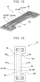
- FIG. 14 is a perspective view illustrating a front support structure 90.
- the front support structure 90 is identical to the front support structure 70 except for a front leaf spring 92.
- the same components are represented by the same reference symbols to omit their description.
- a member indicated by long dashed short dashed lines is made transparent in order to clearly illustrate the shape of the front leaf spring 92.
- the front leaf spring 92 functions as the front suspension member that supports the seat cushion 14 at its front while the seat cushion 14 is suspended from the seat cushion support frame 18.
- Two right and left front leaf springs 92 are arranged in an inverted V-shape in front view, and are arranged such that the front leaf springs 92 are inclined forward in side view, that is, the upper ends are located on a front side with respect to the lower ends.
- the front leaf spring 92 is arranged such that its thickness direction is orthogonal to the front-rear direction.
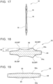
- FIG. 15 to FIG. 19 are diagrams illustrating the shape of the front leaf spring 92.
- FIG. 15 is a perspective view.
- FIG. 16 is a front view illustrating the widest surface (plate surface).
- FIG. 17 is a right-hand side view of FIG. 16 .
- FIG. 18 and FIG. 19 are sectional views taken along lines XVIII-XVIII and XIX-XIX in FIG. 16 , respectively.
- the front leaf spring 92 has a C-shape, and is arranged such that an open side of the C-shape is oriented rearward as illustrated in FIG. 14 when mounted.
- the front leaf spring 92 includes a base plate 94 and ridges 96.
- the base plate 94 has a uniform thickness.
- the ridges 96 project from the base plate 94, and extends in a longitudinal direction of the front leaf spring 92.
- the thickness of the base plate 94 is defined at the thinnest portion of the front leaf spring 92.
- the ridges 96 project from a plate surface 94a orthogonal to the thickness direction.
- the ridges 96 are formed on both front and back surfaces of the base plate 94, but the ridges 96 may be formed on one surface alone.
- the height of the ridges 96 that is, the distance from the plate surface 94a to the top is large at both ends in the longitudinal direction of the front leaf spring 92, and gradually decreases toward the center.
- the ridge 96 is provided at the center of the front leaf spring 92 in its width direction, and the front leaf spring 92 is thin at both edges in the width direction.
- the stress increases at the ridge 96, and decreases at the edges. It may be likely that the edge is cracked.
- the ridge 96 has two ridge lines 98 extending in parallel along the longitudinal direction. By providing the two ridge lines 98 spaced away from each other in the width direction, torsional stiffness can be increased as compared to a case of one ridge line.
- the height of the ridge 96 may be set larger on a rear ridge line 98R than a front ridge line 98F.
- the stress increases at inner corners 100 of the C-shape.
- the stress at the corners 100 can further be reduced.
- the front leaf spring 92 may be made of a fiber reinforced resin.
- the front leaf spring 92 may be made of a carbon fiber reinforced resin.
- the front leaf spring 92 may be made of a unidirectional fiber reinforced resin in which reinforcement fibers extend in the longitudinal direction of the front leaf spring 92.
- FIG. 20 is a diagram illustrating distribution of a stress that occurs when the front leaf spring 92 is deflected.
- FIG. 21 illustrates, as a comparative example, stress distribution of a front leaf spring 92B having a uniform thickness. The stress is highest at a cross-hatched portion. The stress decreases in order from a hatched portion to a dotted portion. In the case of a uniform thickness (see FIG. 21 ), a high stress occurs at the corner 100. When the ridges 96 are provided, the stress increases at the ridges 96, and decreases at the edge including the corners 100.
- FIG. 22 to FIG. 27 are diagrams illustrating another example of the rear leaf spring.
- FIG. 22 is a perspective view illustrating a rear support structure 102.
- the rear support structure 102 is identical to the rear support structure 46 or 62 except for a rear leaf spring 104.
- the same components are represented by the same reference symbols to omit their description.
- one rear leaf spring 104 is arranged behind the rear coupling bar 42.
- the rear leaf spring 104 functions as the rear suspension member that supports the seat cushion 14 at its rear while the seat cushion 14 is suspended from the seat cushion support frame 18.
- Two right and left rear leaf springs 104 are arranged in an inverted V-shape in front view, and are arranged such that the rear leaf springs 104 are inclined forward in side view, that is, the upper ends are located on a front side with respect to the lower ends.
- FIG. 23 to FIG. 27 are diagrams illustrating the shape of the rear leaf spring 104.
- FIG. 23 is a perspective view.
- FIG. 24 is a front view illustrating the widest surface (plate surface).
- FIG. 25 is a right-hand side view of FIG. 24 .
- FIG. 26 and FIG. 27 are sectional views taken along lines XXVI-XXVI and XXVII-XXVII in FIG. 24 , respectively.
- the rear leaf spring 104 has an elongated rectangular shape.
- the rear leaf spring 104 includes a base plate 106 and ridges 108.
- the base plate 106 has a uniform thickness.
- the ridge 108 projects from the base plate 106, and extends in a longitudinal direction of the rear leaf spring 104.
- the thickness of the base plate 106 is defined at the thinnest portion of the rear leaf spring 104.
- the ridge 108 projects from a plate surface 106a orthogonal to a thickness direction.
- the ridges 108 are formed on both front and back surfaces of the base plate 106, but the ridges 108 may be formed on one surface alone.
- the height of the ridges 108 that is, the distance from the plate surface 106a to the top is large at both ends in the longitudinal direction of the rear leaf spring 104, and gradually decreases toward the center.
- the ridge 108 is provided at the center of the rear leaf spring 104 in its width direction, and the rear leaf spring 104 is thin at both edges in the width direction.
- the stress increases at the ridge 108, and decreases at the edges. It may be likely that the edge is cracked.
- the ridge 108 has two ridge lines 110 extending in parallel along the longitudinal direction. By providing the two ridge lines 110 spaced away from each other in the width direction, torsional stiffness can be increased as compared to a case of one ridge line.
- the heights of the two ridge lines 110 may be substantially equal.
- the rear leaf spring 104 may be made of a fiber reinforced resin.
- the rear leaf spring 104 may be made of a carbon fiber reinforced resin.
- the rear leaf spring 104 may be made of a unidirectional fiber reinforced resin in which reinforcement fibers extend in the longitudinal direction of the rear leaf spring 104.
- FIG. 28 is a diagram illustrating distribution of a stress that occurs when the rear leaf spring 104 is deflected.
- FIG. 29 illustrates, as a comparative example, stress distribution of a rear leaf spring 104B having a uniform thickness. The stress is highest at a cross-hatched portion. The stress decreases in order from a hatched portion to a dotted portion. In the case of a uniform thickness (see FIG. 29 ), a high stress occurs over the total width of the end. When the ridges 108 are provided, the stress increases at the ridges 108, and decreases at the edge.
- FIG. 30 is a diagram illustrating the sectional shape of a front leaf spring 112.
- the front leaf spring 112 has the same shape as that of the front leaf spring 92 except for the sectional shape.
- the ridge lines are formed sharply.
- ridge lines 114 are formed gently.
- FIG. 31 is a diagram illustrating the sectional shape of a rear leaf spring 116.
- the rear leaf spring 116 has the same shape as that of the rear leaf spring 104 except for the sectional shape.
- the ridge lines are formed sharply.
- ridge lines 118 are formed gently.
- Each of the front leaf spring and the rear leaf spring may have a shape in which the thickness is uniform in the width direction, large at the ends in the longitudinal direction, and small at the center in the longitudinal direction
- the vehicle seat 10 is a front seat that is slidable in the front-rear direction and of which the angle of the seatback is adjustable.
- the support structures for the seat cushion and the seatback may also be employed in a slidable rear seat or the like, and may also be applied to a seat such as a rear seat of a sedan without one or both of the slide function and the seatback angle adjusting function.
Landscapes
- Engineering & Computer Science (AREA)
- Aviation & Aerospace Engineering (AREA)
- Transportation (AREA)
- Mechanical Engineering (AREA)
- Seats For Vehicles (AREA)
Description
- The invention relates to a vehicle seat, and more particularly, to a seat cushion.
-
US 2016/355238 A describes a seat base comprising a first mounting surface face adapted to couple a seat to the seat base; a second mounting surface adapted to couple the seat base to a surface of a small marine vessel; and a spring/damper assembly positioned between and connected to the first and second mounting surfaces. The spring/damper assembly comprises at least one spring/damper element, the at least one spring/damper element comprising a first flexible member having a first end connected to the first mounting surface and a second flexible member having a first end connected to the second mounting surface and a second end coupled to a second end of the first flexible member.US2002/145321 A describes a seating structure which provides improved comfort and includes a single, pair, or multiple numbers of moving seating assemblies with independent platforms, especially suited for the automotive or aircraft seating environments. A motion mechanism provides each seating assembly with at least one of total rocking, vertical up and down movement, lateral, and limited slight turning movement and in one embodiment generally constrains the seat members of the seat assemblies from interference with each other. The seating assemblies are provided at a neutral angle that corresponds to the particular application of the seat. Independent up and down movement, and rocking, improves seating comfort health, and safety especially as applied to a seating environment, where a user is likely to be seated for an extended period, such as in an automobile or aircraft. There is known a vehicle seat in which lateral movement of a seat cushion relative to a frame of the vehicle seat is permitted. For example,Japanese Unexamined Patent Application Publication No. 2015-229442 JP 2015-229442 A movable cushion 18 supported on aseat cushion frame 16 vialeaf springs 26. Theleaf spring 26 extends rearward from the front end of theseat cushion frame 16, and supports themovable cushion 18 at the rear end. Themovable cushion 18 is movable in a lateral direction through deflection of theleaf spring 26. Theleaf spring 26 functions as a beam that supports themovable cushion 18 in a cantilever manner. The reference symbols described above are used inJP 2015-229442 A - In
JP 2015-229442 A - The invention provides a simple support structure that supports a seat cushion while permitting lateral movement.
- According to the present invention, there is provided a vehicle seat as defined in appended claim 1.
- By supporting the seat cushion in a suspended manner, a bending load acting on the suspension member can be reduced, and the stiffness of the suspension member can be reduced.
- In the aspect described above, a distance between upper ends of the suspension members may be smaller than a distance between lower ends of the rear suspension members. Thus, the seat cushion pivots. When the seat cushion moves rightward, the seat cushion is tilted so that the right edge is higher. When the seat cushion moves leftward, the seat cushion is tilted so that the left edge is higher.
- In the aspect described above, the front suspension members may be provided at the two positions. According to this aspect, a load on one front suspension member is reduced as compared to a case where the front suspension member is provided at one position. Thus, the durability can be improved. When the front suspension member is provided at one position, it is necessary to arrange the front suspension member at the center. By providing the front suspension members at the two positions, the degree of freedom increases in terms of arrangement positions of the front suspension members.
- In the aspect described above, the front suspension members may be provided at the two positions, and a distance between upper ends of the front suspension members may be smaller than a distance between lower ends of the front suspension members. Thus, the seat cushion pivots. When the seat cushion moves rightward, the seat cushion is tilted so that the right edge is higher. When the seat cushion moves leftward, the seat cushion is tilted so that the left edge is higher.
- In the aspect described above, the front suspension member may be located at a center of the vehicle seat in the lateral direction.
- In the aspect described above, the seat cushion support frame may include two side members located on right and left sides and a coupling bar that extends in the lateral direction and couples the side members. Upper ends of the rear suspension members may be fixed to the coupling bar.
- In the aspect described above, the vehicle seat may further include a seatback support frame coupled to the seat cushion support frame. The seatback may be supported on the seatback support frame so as to be swingable in the lateral direction.
- In the aspect described above, one of the rear suspension member and the front suspension member or each of the rear suspension member and the front suspension member may be a leaf spring. One end of the leaf spring may be fixed to a member on a seat cushion support frame side. Thus, the moved seat cushion can be returned by an elastic force of the leaf spring.
- In the aspect described above, one of the rear suspension member and the front suspension member or each of the rear suspension member and the front suspension member may be a leaf spring. An upper end of the leaf spring may be fixed to a member on a seat cushion support frame side, and a lower end of the leaf spring may be fixed to a member on a seat cushion side. A ridge may be formed on a plate surface of the leaf spring so as to project from the plate surface and extend along a longitudinal direction of the leaf spring. A height of the ridge may gradually decrease from an upper end portion and a lower end portion toward a center in the longitudinal direction of the leaf spring. In the aspect described above, the ridge of the leaf spring may have two ridge lines extending in parallel along the longitudinal direction of the leaf spring.
- In the aspect described above, each of the front suspension members may be a leaf spring in which an upper end is fixed to a member on a seat cushion support frame side and a lower end is fixed to a member on a seat cushion side. The upper end of the leaf spring may be located ahead of the lower end of the leaf spring. The leaf spring may have a C-shape open to a rear. A ridge may be formed on a plate surface of the leaf spring so as to project from the plate surface and extend along a longitudinal direction of the leaf spring. A height of the ridge may gradually decrease from an upper end portion and a lower end portion toward a center in the longitudinal direction of the leaf spring. The ridge may have two ridge lines extending in parallel along the longitudinal direction of the leaf spring. The height of the ridge may be larger on the ridge line located at a rear than the ridge line located at a front.
- In the aspect described above, one of the rear suspension member and the front suspension member or each of the rear suspension member and the front suspension member may be a leaf spring. An upper end of the leaf spring may be fixed to a member on a seat cushion support frame side, and a lower end of the leaf spring may be fixed to a member on a seat cushion side. The leaf spring may have a thick portion that is provided at least at each end in a longitudinal direction of the leaf spring and the thick portion has a large dimension in a thickness direction at least in part in a width direction of the leaf spring. The dimension of the thick portion in the thickness direction may gradually decrease from the end toward a center in the longitudinal direction of the leaf spring.
- In the aspect described above, the leaf spring may be made of a fiber reinforced resin.
- The bending load acting on the suspension member can be reduced, and the support structure for the seat cushion can be simplified.
- Features, advantages, and technical and industrial significance of exemplary embodiments of the invention will be described below with reference to the accompanying drawings, in which like numerals denote like elements, and wherein:
-
FIG. 1 is a perspective view illustrating an overall vehicle seat of an embodiment; -
FIG. 2A is a diagram illustrating a seat cushion, a seat cushion support frame, and support structures that suspend the seat cushion, and illustrating an upper side of the seat cushion; -
FIG. 2B is a diagram illustrating the seat cushion, the seat cushion support frame, and the support structures that suspend the seat cushion, and illustrating a lower side of the seat cushion; -
FIG. 3 is a local view illustrating the support structures and the seat cushion that is a component on a movement side inFIG. 2A ; -
FIG. 4 is a local view illustrating the support structures and the seat cushion support frame that is a component on a stationary side inFIG. 2A ; -
FIG. 5 is a local view illustrating the support structures and the seat cushion that is a component on the movement side inFIG. 2B ; -
FIG. 6 is a local view illustrating the support structures and the seat cushion support frame that is a component on the stationary side inFIG. 2B ; -
FIG. 7 is a rear view illustrating the seat cushion and the seat cushion support frame; -
FIG. 8 is an explanatory drawing of movement of the seat cushion; -
FIG. 9 is a diagram illustrating another form of a rear support structure; -
FIG. 10 is a diagram illustrating another form of a front support structure that is viewed obliquely downward from the rear; -
FIG. 11 is a diagram illustrating the other form of the front support structure that is viewed obliquely upward from the front; -
FIG. 12 is a diagram illustrating a retaining structure for the seat cushion using wires; -
FIG. 13 is a diagram illustrating a retaining structure for the seat cushion using a hook; -
FIG. 14 is a diagram illustrating still another form of the front support structure; -
FIG. 15 is a perspective view illustrating an example of a front leaf spring; -
FIG. 16 is a front view of the front leaf spring illustrated inFIG. 15 ; -
FIG. 17 is a side view of the front leaf spring illustrated inFIG. 15 ; -
FIG. 18 is a sectional view of the front leaf spring taken along a line XVIII-XVIII inFIG. 16 ; -
FIG. 19 is a sectional view of the front leaf spring taken along a line XIX-XIX inFIG. 16 ; -
FIG. 20 is a diagram illustrating stress distribution of the front leaf spring illustrated inFIG. 15 ; -
FIG. 21 is a diagram illustrating stress distribution of a front leaf spring having a uniform thickness; -
FIG. 22 is a diagram illustrating still another form of the rear support structure; -
FIG. 23 is a perspective view illustrating an example of a rear leaf spring; -
FIG. 24 is a front view of the rear leaf spring illustrated inFIG. 23 ; -
FIG. 25 is a side view of the rear leaf spring illustrated inFIG. 23 ; -
FIG. 26 is a sectional view of the rear leaf spring taken along a line XXVI-XXVI inFIG. 24 ; -
FIG. 27 is a sectional view of the rear leaf spring taken along a line XXVII-XXVII inFIG. 24 ; -
FIG. 28 is a diagram illustrating stress distribution of the rear leaf spring illustrated inFIG. 23 ; -
FIG. 29 is a diagram illustrating stress distribution of a rear leaf spring having a uniform thickness; -
FIG. 30 is a diagram illustrating an example of the sectional shape of the front leaf spring; and -
FIG. 31 is a diagram illustrating an example of the sectional shape of the rear leaf spring. - A
vehicle seat 10 of an embodiment of the invention is described below with reference to the drawings. In the following description, terms "front", "rear", "right", "left", "up", and "down" mean directions or orientations in relation to an occupant seated on the vehicle seat 10 (hereinafter referred to as a seated person) unless otherwise noted. In the drawings, a direction indicated by an arrow FR is a front side, a direction indicated by an arrow UP is an upper side, and a direction indicated by an arrow LH is a left side. -
FIG. 1 is a perspective view schematically illustrating the overall structure of thevehicle seat 10. InFIG. 1 , components are omitted in part. Thevehicle seat 10 is a front seat applied to an automobile such as a passenger car. Thevehicle seat 10 includes amain frame 12, aseat cushion 14, and aseatback 16. Themain frame 12 is directly mounted on a vehicle body. Theseat cushion 14 and theseatback 16 are movably supported on themain frame 12.FIG. 1 illustrates theseat cushion 14 without a cushion pad. Theseat cushion 14 supports the hip and thighs of the seated person from the bottom. Theseatback 16 supports the upper body of the seated person from the rear. - The
main frame 12 includes a seatcushion support frame 18 and aseatback support frame 20. The seatcushion support frame 18 supports theseat cushion 14. Theseatback support frame 20 supports theseatback 16. The seatcushion support frame 18 hasseat legs 22 at four corners in the bottom. Theseat legs 22 are arranged on afloor 24 of the vehicle, and are coupled to a pair of seat tracks 26 extending in a front-rear direction of the vehicle. Theseat track 26 includes alower rail 28 and anupper rail 30. Thelower rail 28 is fixed to thefloor 24. Theupper rail 30 is slidable relative to thelower rail 28. Theseat legs 22 are coupled to theupper rail 30. Thus, thevehicle seat 10 is mounted on thefloor 24 so as to be slidable in the front-rear direction of the vehicle. Theseatback support frame 20 has an inverted U-shape in front view. The lower end of theseatback support frame 20 is coupled to the rear end of the seatcushion support frame 18. Theseatback support frame 20 is coupled to the seatcushion support frame 18 so as to be pivotable about an axis extending along a lateral direction. By pivoting theseatback support frame 20 relative to the seatcushion support frame 18, the tilt of theseatback 16 can be adjusted. Theseatback support frame 20 may stationarily be coupled to the seatcushion support frame 18. - The
seat cushion 14 includes acushion pan 32 and a cushion pad 34 (seeFIG. 2A ). Thecushion pan 32 is movably supported on the seatcushion support frame 18. Thecushion pad 34 is attached onto thecushion pan 32. A structure that supports thecushion pan 32 is described later in detail. - The
seatback 16 is supported on theseatback support frame 20.FIG. 1 illustrates aseatback pad 36 where the back of the seated person is in contact. A seatback frame (not illustrated) to which theseatback pad 36 is attached is arranged at the back of theseatback pad 36. The seatback frame is supported while being suspended from theseatback support frame 20 by a wire (not illustrated). Thus, theseatback 16 is supported so as to be swingable in the lateral direction relative to themain frame 12. -
FIG. 2A to FIG. 7 are diagrams illustrating theseat cushion 14, the seatcushion support frame 18, and surrounding structures.FIG. 2A and FIG. 2B are diagrams illustrating a state in which theseat cushion 14 and the seatcushion support frame 18 are assembled.FIG. 2A illustrates a state in which theseat cushion 14 and the seatcushion support frame 18 are viewed downward focusing mainly on the rear of theseat cushion 14.FIG. 2B illustrates a state in which theseat cushion 14 and the seatcushion support frame 18 are viewed upward focusing mainly on the front of theseat cushion 14.FIG. 2A illustrates thecushion pan 32 and the seatcushion support frame 18 below thecushion pad 34 in a transparent representation indicated by long dashed short dashed lines. InFIG. 3 and other subsequent figures, thecushion pad 34 is omitted.FIG. 3 andFIG. 5 illustrate a movable part, andFIG. 4 andFIG. 6 illustrate a stationary part. - The seat
cushion support frame 18 includes a pair ofside members 38 and twocoupling bars side members 38 are arranged at the right and left of theseat cushion 14, and extend in the front-rear direction. The coupling bars 40 and 42 couple the right and leftside members 38. Theside member 38 is a roughly plate-shaped member, and is arranged such that its thickness direction corresponds to the lateral direction. Thefront coupling bar 40 out of the twocoupling bars side members 38 at their front ends. Therear coupling bar 42 couples theside members 38 at their rear ends. The seatcushion support frame 18 further includes afront member 44 arranged at the front so as to bridge the right and leftside members 38. Thefront member 44 is a roughly plate-shaped or tray-shaped member, and is arranged such that its thickness direction corresponds to an up-down direction. Thefront member 44 is coupled to the upper front ends of the right and leftside members 38, and projects forward from the front ends of theside members 38 like a canopy. -
Support structures seat cushion 14 are provided at two right and left positions on the rear of theseat cushion 14, and at one central position on the front of theseat cushion 14. Thesupport structures 46 provided at the rear are referred to asrear support structures 46, and thesupport structure 48 provided at the front is referred to as afront support structure 48. - Each of the right and left
rear support structures 46 includes arear support bracket 50, arear suspension bracket 52, and two rear leaf springs 54. Therear support bracket 50 is fixed to therear coupling bar 42 in terms of the front-rear, up-down, and lateral directions, and is coupled to therear coupling bar 42 so as to be pivotable about an axis extending in the lateral direction. Therear suspension bracket 52 is fixed to the rear end of thecushion pan 32. Therear leaf springs 54 are arranged so as to sandwich therear coupling bar 42. The upper ends of therear leaf springs 54 are fixed to therear support bracket 50, and the lower ends of therear leaf springs 54 are fixed to therear suspension bracket 52. That is, the upper ends of therear leaf springs 54 are fixed to therear coupling bar 42 by being fixed to therear support bracket 50, and the lower ends of therear leaf springs 54 are fixed to thecushion pan 32 by being fixed to therear suspension bracket 52. Therear leaf spring 54 functions as a rear suspension member that supports theseat cushion 14 at its rear, that is, at a rear edge where theseatback 16 is provided, while theseat cushion 14 is suspended from the seatcushion support frame 18. The right and leftrear leaf springs 54 are arranged such that the distance between the upper ends is smaller than the distance between the lower ends, and assume an inverted V-shape in rear view. Therear leaf spring 54 is arranged such that its thickness direction is orthogonal to the front-rear direction. Thus, lateral movement of the rear of theseat cushion 14 is permitted, but front-rear movement of the rear of theseat cushion 14 is restricted. For example, therear leaf spring 54 may be made of carbon tool steel or stainless steel having a thickness of 0.8 to 1.0 mm. - The upper end of the
rear leaf spring 54 is sandwiched in the thickness direction between two plate members that are parts of therear support bracket 50. Thus, the upper end of therear leaf spring 54 is a fixed end. The lower end of therear leaf spring 54 is sandwiched between two plate members that are parts of therear suspension bracket 52. Thus, the lower end of therear leaf spring 54 is a fixed end. - The
front support structure 48 includes afront support bracket 56, afront suspension bracket 58, and afront leaf spring 60. Thefront support bracket 56 is fixed to the lower surface of thefront member 44 of the seatcushion support frame 18. Thefront suspension bracket 58 is fixed to the front end of thecushion pan 32, and extends forward. The upper end of thefront leaf spring 60 is fixed to thefront support bracket 56, and the lower end of thefront leaf spring 60 is fixed to thefront suspension bracket 58. Thefront leaf spring 60 functions as a front suspension member that supports theseat cushion 14 at its front while theseat cushion 14 is suspended from the seatcushion support frame 18. Thefront leaf spring 60 is vertically arranged in front view, and is arranged such that its thickness direction corresponds to the lateral direction. Thus, lateral movement of the front of theseat cushion 14 is permitted, but front-rear movement of the front of theseat cushion 14 is restricted. For example, thefront leaf spring 60 may be made of carbon tool steel or stainless steel having a thickness of 0.8 to 1.0 mm. - The upper end of the
front leaf spring 60 is sandwiched in the thickness direction between thefront support bracket 56 and a holding plate. Thus, the upper end of thefront leaf spring 60 is a fixed end. The lower end of thefront leaf spring 60 is sandwiched in the thickness direction between thefront suspension bracket 58 and a holding plate. Thus, the lower end of thefront leaf spring 60 is a fixed end. - The
seat cushion 14 is supported at three positions by therear support structures 46 and thefront support structure 48 while being suspended from the seatcushion support frame 18, and is movable in the lateral direction. In particular, theseat cushion 14 roughly pivots about an axis A illustrated inFIG. 1 . Through the pivot, movement of the seated person at a part near the pivot axis A can be reduced as compared to movement of the seated person at a part near theseat cushion 14, specifically, hip and thighs. -
FIG. 8 is an explanatory drawing of movement of theseat cushion 14.FIG. 8 is a schematic rear view of theseat cushion 14 and the rear leaf springs 54. Continuous lines indicate theseat cushion 14 located at a central position in the lateral direction (hereinafter referred to as a neutral position), and therear leaf springs 54 at this time. At the neutral position, theseat cushion 14 is located horizontally. As described above, the tworear leaf springs 54 are arranged in the inverted V-shape, and lines extending from therear leaf springs 54 intersect at a point O. When theseat cushion 14 moves leftward, the left end is higher and the right end is lower as compared to the case where theseat cushion 14 is located at the neutral position because therear leaf springs 54 are arranged in the inverted V-shape. Thus, theseat cushion 14 is tilted rightward. This state is indicated by long dashed short dashed lines. When theseat cushion 14 moves rightward, theseat cushion 14 is tilted leftward in turn. This movement may be regarded as a pivot about the point O if the movement range is a narrow range, for example, a range of about 3° in terms of a half amplitude. - The upper end and the lower end of the
rear leaf spring 54 are fixed ends, and therear leaf spring 54 is deflected through the lateral movement of theseat cushion 14. An elastic force generated by the deflection may return theseat cushion 14 to the neutral position. When the upper end of therear leaf spring 54, that is, the end on the stationary side is a fixed end, the elastic force for returning theseat cushion 14 to the neutral position, that is, a restoration force is generated. - When the
seat cushion 14 moves in the lateral direction, movement of the front of theseat cushion 14 may be regarded as a pivot about the upper end of thefront leaf spring 60, that is, the end on the stationary side if the movement range is a narrow range. The upper end and the lower end of thefront leaf spring 60 are fixed ends, and thefront leaf spring 60 is deflected when the seat cushion moves in the lateral direction, thereby generating a restoration force for returning the seat cushion to the neutral position. When the upper end of thefront leaf spring 60, that is, the end on the stationary side is a fixed end, the restoration force for returning the seat cushion to the neutral position is generated. - Through the arrangement of the
rear leaf springs 54 and thefront leaf spring 60, the center of the pivot of theseat cushion 14 is higher at the rear and lower at the front. As a result, the pivot axis of theseat cushion 14 corresponds to the axis A inFIG. 1 that is lower at the front. Therear leaf springs 54 and thefront leaf spring 60 may be arranged such that their longitudinal directions are orthogonal to the axis A. Therear leaf springs 54 and thefront leaf spring 60 may also be arranged such that their longitudinal directions correspond to a vertical direction in side view. - The
rear support structure 46 suspends the seat cushion by the pair ofrear leaf springs 54 arranged so as to sandwich therear coupling bar 42, but the invention is not limited to this case. The seat cushion may be suspended by one rear leaf spring alone. Arear support structure 62 illustrated inFIG. 9 includes onerear leaf spring 64 alone. Arear support bracket 66 is fixed to therear coupling bar 42 in terms of the front-rear, up-down, and lateral directions, and is coupled to therear coupling bar 42 so as to be pivotable about an axis extending in the lateral direction. Arear suspension bracket 68 is fixed to the rear edge of thecushion pan 32. The upper end of therear leaf spring 64 is fixed to therear support bracket 66, and the lower end of therear leaf spring 64 is fixed to therear suspension bracket 68. Similarly to therear support structures 46, right and leftrear leaf springs 64 are arranged in an inverted V-shape in rear view. - The
front support structure 48 is arranged at the center in the lateral direction, but the invention is not limited to this case. Similarly to therear support structures 46, front support structures may be arranged at two right and left positions. In this case, front leaf springs may be arranged in an inverted V-shape similarly to the rear leaf springs 54. An intersection of lines extending from the two front leaf springs arranged in the inverted V-shape is a center of a pivot of the front of the seat cushion. A line connecting the centers of the pivot of the front and the rear is a pivot axis of the seat cushion. In this case as well, the pivot axis may be lower at the front. -
FIG. 10 andFIG. 11 are diagrams illustrating an example in whichfront support structures 70 are arranged at two right and left positions.FIG. 10 is a diagram illustrating thecushion pan 32 that is viewed obliquely downward from the rear in a state in which a bottom plate is partially cut awayFIG. 11 is a diagram illustrating thecushion pan 32 that is viewed obliquely upward from the front. Eachfront support structure 70 includes afront support bracket 72, afront suspension bracket 74, and afront leaf spring 76. Thefront support bracket 72 is fixed to the front coupling bar 40 (seeFIG. 4 ) in terms of the front-rear, up-down, and lateral directions, and is coupled to thefront coupling bar 40 so as to be pivotable about an axis extending in the lateral direction. The upper end of thefront suspension bracket 74 is fixed to areinforcement bar 78 provided at the front edge of thecushion pan 32, and thefront suspension bracket 74 extends downward. The upper end of thefront leaf spring 76 is fixed to thefront support bracket 72, and the lower end of thefront leaf spring 76 is fixed to the lower end of thefront suspension bracket 74. Thefront leaf spring 76 functions as the front suspension member that supports theseat cushion 14 at its front while theseat cushion 14 is suspended from the seatcushion support frame 18. Two right and leftfront leaf springs 76 are arranged in an inverted V-shape in front view. Thefront leaf spring 76 is arranged such that its thickness direction is orthogonal to the front-rear direction. Thus, lateral movement of the front of theseat cushion 14 is permitted, but front-rear movement of the front of theseat cushion 14 is restricted. For example, thefront leaf spring 76 may be made of carbon tool steel or stainless steel having a thickness of 0.8 to 1.0 mm. - The upper end of the
front leaf spring 76 is sandwiched in the thickness direction between thefront support bracket 72 and a holding plate. Thus, the upper end of thefront leaf spring 76 is a fixed end. The lower end of thefront leaf spring 76 is sandwiched in the thickness direction between thefront suspension bracket 74 and a holding plate. Thus, the lower end of thefront leaf spring 76 is a fixed end. - It is desirable that the
seat cushion 14 be prevented from falling when the suspension member such as the leaf spring is broken.FIG. 12 andFIG. 13 are diagrams illustrating retaining members.FIG. 12 andFIG. 13 illustrate therear support structure 46 in which theleaf spring 54 on the front side out of the twoleaf springs 54 is omitted and theleaf spring 54 on the rear side is left alone.FIG. 12 is a diagram illustrating a retaining structure using wires. A retainingwire 80 is looped around therear suspension bracket 52 and therear coupling bar 42. A retainingwire 82 is looped around therear suspension bracket 52 and therear support bracket 50. Therear suspension bracket 52 is a member integrated with theseat cushion 14. Therear coupling bar 42 and therear support bracket 50 are parts of the seatcushion support frame 18 or members integrated with the seatcushion support frame 18. Thus, when therear leaf spring 54 is broken, theseat cushion 14 is suspended by the retainingwires -
FIG. 13 is a diagram illustrating a retaining structure using a hook. A retaininghook 84 is coupled to therear suspension bracket 52, and is arranged such that the distal end is hooked on therear coupling bar 42. Therear suspension bracket 52 is a member integrated with theseat cushion 14. When therear leaf spring 54 is broken, the retaininghook 84 is hooked on therear coupling bar 42, whereby theseat cushion 14 is restrained from falling. - Wires or rods each movably coupled at the upper end and the lower end like a joint may be used in place of the leaf springs of the
rear support structure front support structure rear support structure front support structure - The
rear support bracket rear support structure rear coupling bar 42 of the seatcushion support frame 18, but may be fixed to another portion of the seatcushion support frame 18. Similarly, thefront support bracket 72 of thefront support structure 70 may be fixed to a portion of the seatcushion support frame 18 other than thefront coupling bar 40. -
FIG. 14 to FIG. 19 are diagrams illustrating another example of the front leaf spring.FIG. 14 is a perspective view illustrating afront support structure 90. Thefront support structure 90 is identical to thefront support structure 70 except for afront leaf spring 92. The same components are represented by the same reference symbols to omit their description. InFIG. 14 , a member indicated by long dashed short dashed lines is made transparent in order to clearly illustrate the shape of thefront leaf spring 92. Similarly to thefront leaf spring 76, thefront leaf spring 92 functions as the front suspension member that supports theseat cushion 14 at its front while theseat cushion 14 is suspended from the seatcushion support frame 18. Two right and leftfront leaf springs 92 are arranged in an inverted V-shape in front view, and are arranged such that thefront leaf springs 92 are inclined forward in side view, that is, the upper ends are located on a front side with respect to the lower ends. Thefront leaf spring 92 is arranged such that its thickness direction is orthogonal to the front-rear direction. -
FIG. 15 to FIG. 19 are diagrams illustrating the shape of thefront leaf spring 92.FIG. 15 is a perspective view.FIG. 16 is a front view illustrating the widest surface (plate surface).FIG. 17 is a right-hand side view ofFIG. 16 .FIG. 18 and FIG. 19 are sectional views taken along lines XVIII-XVIII and XIX-XIX inFIG. 16 , respectively. - As illustrated in
FIG. 16 , thefront leaf spring 92 has a C-shape, and is arranged such that an open side of the C-shape is oriented rearward as illustrated inFIG. 14 when mounted. Thefront leaf spring 92 includes abase plate 94 andridges 96. Thebase plate 94 has a uniform thickness. Theridges 96 project from thebase plate 94, and extends in a longitudinal direction of thefront leaf spring 92. The thickness of thebase plate 94 is defined at the thinnest portion of thefront leaf spring 92. Theridges 96 project from aplate surface 94a orthogonal to the thickness direction. In thefront leaf spring 92, theridges 96 are formed on both front and back surfaces of thebase plate 94, but theridges 96 may be formed on one surface alone. The height of theridges 96, that is, the distance from theplate surface 94a to the top is large at both ends in the longitudinal direction of thefront leaf spring 92, and gradually decreases toward the center. By increasing the height of theridges 96, that is, the thickness of thefront leaf spring 92 at the ends, the strength of each end where a stress concentrates is increased. By reducing the thickness at the center, overall deflection of thefront leaf spring 92 is secured. - As illustrated in
FIG. 18 , theridge 96 is provided at the center of thefront leaf spring 92 in its width direction, and thefront leaf spring 92 is thin at both edges in the width direction. Thus, the stress increases at theridge 96, and decreases at the edges. It may be likely that the edge is cracked. By reducing the stress at the edge, it is possible to reduce the occurrence of a case where thefront leaf spring 92 is torn off due to the crack in the edge. Theridge 96 has two ridge lines 98 extending in parallel along the longitudinal direction. By providing the two ridge lines 98 spaced away from each other in the width direction, torsional stiffness can be increased as compared to a case of one ridge line. The height of theridge 96 may be set larger on a rear ridge line 98R than a front ridge line 98F. In thefront leaf spring 92, the stress increases atinner corners 100 of the C-shape. By increasing the height of the rear ridge line 98R, the stress at thecorners 100 can further be reduced. - The
front leaf spring 92 may be made of a fiber reinforced resin. In particular, thefront leaf spring 92 may be made of a carbon fiber reinforced resin. Further, thefront leaf spring 92 may be made of a unidirectional fiber reinforced resin in which reinforcement fibers extend in the longitudinal direction of thefront leaf spring 92. -
FIG. 20 is a diagram illustrating distribution of a stress that occurs when thefront leaf spring 92 is deflected.FIG. 21 illustrates, as a comparative example, stress distribution of afront leaf spring 92B having a uniform thickness. The stress is highest at a cross-hatched portion. The stress decreases in order from a hatched portion to a dotted portion. In the case of a uniform thickness (seeFIG. 21 ), a high stress occurs at thecorner 100. When theridges 96 are provided, the stress increases at theridges 96, and decreases at the edge including thecorners 100. -
FIG. 22 to FIG. 27 are diagrams illustrating another example of the rear leaf spring.FIG. 22 is a perspective view illustrating arear support structure 102. Therear support structure 102 is identical to therear support structure rear leaf spring 104. The same components are represented by the same reference symbols to omit their description. In therear support structure 102, onerear leaf spring 104 is arranged behind therear coupling bar 42. Similarly to therear leaf spring 54, therear leaf spring 104 functions as the rear suspension member that supports theseat cushion 14 at its rear while theseat cushion 14 is suspended from the seatcushion support frame 18. Two right and leftrear leaf springs 104 are arranged in an inverted V-shape in front view, and are arranged such that therear leaf springs 104 are inclined forward in side view, that is, the upper ends are located on a front side with respect to the lower ends. -
FIG. 23 to FIG. 27 are diagrams illustrating the shape of therear leaf spring 104.FIG. 23 is a perspective view.FIG. 24 is a front view illustrating the widest surface (plate surface).FIG. 25 is a right-hand side view ofFIG. 24 .FIG. 26 and FIG. 27 are sectional views taken along lines XXVI-XXVI and XXVII-XXVII inFIG. 24 , respectively. - As illustrated in
FIG. 23 , therear leaf spring 104 has an elongated rectangular shape. Therear leaf spring 104 includes abase plate 106 andridges 108. Thebase plate 106 has a uniform thickness. Theridge 108 projects from thebase plate 106, and extends in a longitudinal direction of therear leaf spring 104. The thickness of thebase plate 106 is defined at the thinnest portion of therear leaf spring 104. Theridge 108 projects from aplate surface 106a orthogonal to a thickness direction. In therear leaf spring 104, theridges 108 are formed on both front and back surfaces of thebase plate 106, but theridges 108 may be formed on one surface alone. The height of theridges 108, that is, the distance from theplate surface 106a to the top is large at both ends in the longitudinal direction of therear leaf spring 104, and gradually decreases toward the center. By increasing the height of theridges 108, that is, the thickness of therear leaf spring 104 at the ends, the strength of each end where a stress concentrates is increased. By reducing the thickness at the center, overall deflection of therear leaf spring 104 is secured. - As illustrated in
FIG. 26 , theridge 108 is provided at the center of therear leaf spring 104 in its width direction, and therear leaf spring 104 is thin at both edges in the width direction. Thus, the stress increases at theridge 108, and decreases at the edges. It may be likely that the edge is cracked. By reducing the stress at the edge, it is possible to reduce the occurrence of a case where therear leaf spring 104 is torn off due to the crack in the edge. Theridge 108 has tworidge lines 110 extending in parallel along the longitudinal direction. By providing the tworidge lines 110 spaced away from each other in the width direction, torsional stiffness can be increased as compared to a case of one ridge line. The heights of the tworidge lines 110 may be substantially equal. - The
rear leaf spring 104 may be made of a fiber reinforced resin. In particular, therear leaf spring 104 may be made of a carbon fiber reinforced resin. Therear leaf spring 104 may be made of a unidirectional fiber reinforced resin in which reinforcement fibers extend in the longitudinal direction of therear leaf spring 104. -
FIG. 28 is a diagram illustrating distribution of a stress that occurs when therear leaf spring 104 is deflected.FIG. 29 illustrates, as a comparative example, stress distribution of arear leaf spring 104B having a uniform thickness. The stress is highest at a cross-hatched portion. The stress decreases in order from a hatched portion to a dotted portion. In the case of a uniform thickness (seeFIG. 29 ), a high stress occurs over the total width of the end. When theridges 108 are provided, the stress increases at theridges 108, and decreases at the edge. -
FIG. 30 is a diagram illustrating the sectional shape of afront leaf spring 112. Thefront leaf spring 112 has the same shape as that of thefront leaf spring 92 except for the sectional shape. In the sectional shape of thefront leaf spring 92 indicated by long dashed short dashed lines, the ridge lines are formed sharply. In thefront leaf spring 112,ridge lines 114 are formed gently.FIG. 31 is a diagram illustrating the sectional shape of arear leaf spring 116. Therear leaf spring 116 has the same shape as that of therear leaf spring 104 except for the sectional shape. In the sectional shape of therear leaf spring 104 indicated by long dashed short dashed lines, the ridge lines are formed sharply. In therear leaf spring 116,ridge lines 118 are formed gently. When a leaf spring made of a fiber reinforced resin is manufactured by laminating pre-pregs, gentle ridge lines are advantageous. - Each of the front leaf spring and the rear leaf spring may have a shape in which the thickness is uniform in the width direction, large at the ends in the longitudinal direction, and small at the center in the longitudinal direction
- The
vehicle seat 10 is a front seat that is slidable in the front-rear direction and of which the angle of the seatback is adjustable. The support structures for the seat cushion and the seatback may also be employed in a slidable rear seat or the like, and may also be applied to a seat such as a rear seat of a sedan without one or both of the slide function and the seatback angle adjusting function.
Claims (13)
- A vehicle seat (10), comprising:a seat cushion (14) that supports a hip and thighs of a seated person;a seatback (16) that supports an upper body of the seated person from a rear;a seat cushion support frame (18) stationarily or slidably attached to a vehicle body;wherein the seat cushion (14) is suspended from the seat cushion support frame (18);characterized in that:rear suspension members (54; 64; 104; 116) are provided at two positions spaced away from each other in a lateral direction on an edge of the seat cushion (14) near the seatback, the rear suspension members (54; 64; 104; 116) supporting the seat cushion (14) while the seat cushion (14) is suspended from the seat cushion support frame (18) so that the seat cushion (14) is movable in the lateral direction; anda front suspension member (60; 76; 92; 112) is provided at one position or at each of two positions spaced away from each other in the lateral direction andahead of the rear suspension members (54; 64; 104; 116), the front suspension member (60; 76; 92; 112) supporting the seat cushion (14) while the seat cushion (14) is suspended from the seat cushion support frame (18) so that the seat cushion (14) is movable in the lateral direction.
- The vehicle seat according to claim 1, wherein a distance between upper ends of the rear suspension members (54; 64; 104; 116) is smaller than a distance between lower ends of the rear suspension members (54; 64; 104; 116).
- The vehicle seat according to claim 1, wherein the front suspension members (76; 92; 112) are provided at the two positions.
- The vehicle seat according to claim 2, wherein:the front suspension members (76; 92; 112) are provided at the two positions; anda distance between upper ends of the front suspension members (76; 92; 112) is smaller than a distance between lower ends of the front suspension members (76; 92; 112).
- The vehicle seat according to claim 2, wherein the front suspension member (60) is located at a center of the vehicle seat (10) in the lateral direction.
- The vehicle seat according to any one of claims 1 to 5, whereinthe seat cushion support frame (18) includes two side members (38) located on right and left sides and a coupling bar (42) that extends in the lateral direction and couples the side members (38), andupper ends of the rear suspension members (54; 64; 104; 116) are fixed to the coupling bar (42).
- The vehicle seat according to any one of claims 1 to 6, further comprising a seatback support frame (20) coupled to the seat cushion support frame (18), wherein the seatback (16) is supported on the seatback support frame (20) so as to be swingable in the lateral direction.
- The vehicle seat according to any one of claims 1 to 7, whereinone of the rear suspension member (54; 64; 104; 116) and the front suspension member (60; 76; 92; 112) or each of the rear suspension member (54; 64; 104; 116) and the front suspension member (60; 76; 92; 112) is a leaf spring, andone end of the leaf spring is fixed to a member on a seat cushion support frame side.
- The vehicle seat according to any one of claims 1 to 7, whereinone of the rear suspension member (104; 116) and the front suspension member (92; 112) or each of the rear suspension member (104; 116) and the front suspension member (92; 112) is a leaf spring,an upper end of the leaf spring is fixed to a member on a seat cushion support frame side, and a lower end of the leaf spring is fixed to a member on a seat cushion side,a ridge (96; 108) is formed on a plate surface of the leaf spring so as to project from the plate surface and extend along a longitudinal direction of the leaf spring, anda height of the ridge (96; 108) gradually decreases from an upper end portion and a lower end portion toward a center in the longitudinal direction of the leaf spring.
- The vehicle seat according to claim 9, wherein the ridge (96; 108) of the leaf spring has two ridge lines (98; 110; 114; 118) extending in parallel along the longitudinal direction of the leaf spring.
- The vehicle seat according to claim 4, wherein:each of the front suspension members (92; 112) is a leaf spring in which an upper end is fixed to a member on a seat cushion support frame side and a lower end is fixed to a member on a seat cushion side;the upper end of the leaf spring is located ahead of the lower end of the leaf spring;the leaf spring has a C-shape open to a rear;a ridge (96) is formed on a plate surface of the leaf spring so as to project from the plate surface and extend along a longitudinal direction of the leaf spring;a height of the ridge (96) gradually decreases from an upper end portion and a lower end portion toward a center in the longitudinal direction of the leaf spring;the ridge (96) has two ridge lines (98; 114) extending in parallel along the longitudinal direction of the leaf spring; andthe height of the ridge (96) is larger on the ridge line (98; 114) located at a rear than the ridge line (98; 114) located at a front.
- The vehicle seat according to any one of claims 1 to 7, wherein:one of the rear suspension member (54; 64; 104; 116) and the front suspension member (60; 76; 92; 112) or each of the rear suspension member and the front suspension member is a leaf spring;an upper end of the leaf spring is fixed to a member on a seat cushion support frame side, and a lower end of the leaf spring is fixed to a member on a seat cushion side;the leaf spring has a thick portion that is provided at least at each end in a longitudinal direction of the leaf spring and the thick portion has a large dimension in a thickness direction at least in part in a width direction of the leaf spring; andthe dimension of the thick portion in the thickness direction gradually decreases from the end toward a center in the longitudinal direction of the leaf spring.
- The vehicle seat according to any one of claims 8 to 12, wherein the leaf spring is made of a fiber reinforced resin.
Applications Claiming Priority (2)
| Application Number | Priority Date | Filing Date | Title |
|---|---|---|---|
| JP2019033162 | 2019-02-26 | ||
| JP2019155694A JP7107902B2 (en) | 2019-02-26 | 2019-08-28 | vehicle seat |
Publications (2)
| Publication Number | Publication Date |
|---|---|
| EP3702209A1 EP3702209A1 (en) | 2020-09-02 |
| EP3702209B1 true EP3702209B1 (en) | 2023-06-21 |
Family
ID=69570542
Family Applications (1)
| Application Number | Title | Priority Date | Filing Date |
|---|---|---|---|
| EP20156398.8A Active EP3702209B1 (en) | 2019-02-26 | 2020-02-10 | Vehicle seat |
Country Status (3)
| Country | Link |
|---|---|
| US (1) | US11472320B2 (en) |
| EP (1) | EP3702209B1 (en) |
| CN (1) | CN111605447B (en) |
Families Citing this family (1)
| Publication number | Priority date | Publication date | Assignee | Title |
|---|---|---|---|---|
| JP7059896B2 (en) * | 2018-11-01 | 2022-04-26 | トヨタ自動車株式会社 | Vehicle seat |
Family Cites Families (30)
| Publication number | Priority date | Publication date | Assignee | Title |
|---|---|---|---|---|
| US2568832A (en) * | 1950-07-26 | 1951-09-25 | Marshall E Stone | Wagon and truck body seat |
| US2638965A (en) * | 1950-11-29 | 1953-05-19 | Walter F Woodin | Tractor seat mount |
| JPH0388850U (en) | 1989-12-27 | 1991-09-11 | ||
| US5474353A (en) * | 1993-12-01 | 1995-12-12 | Hoover Universal, Inc. | Pivoting seat cushion arrangement for vehicle seat assemblies |
| US5913568A (en) * | 1997-09-30 | 1999-06-22 | Brightbill; Stephen T. | Two platform motion seat |
| KR20040046612A (en) * | 2002-11-28 | 2004-06-05 | 현대자동차주식회사 | Structure of seatcusion for adjusting sitting-sense in automobile |
| DE102006038298B3 (en) * | 2006-05-08 | 2007-12-13 | Johnson Controls Gmbh | Vehicle seat, seat assembly and motor vehicle |
| PT1908374E (en) | 2006-10-06 | 2009-05-18 | Stoll Giroflex Ag | Synchronous office chair |
| SE531594C2 (en) * | 2007-10-26 | 2009-06-02 | Scania Cv Abp | chair base |
| DE102008059999A1 (en) * | 2008-12-02 | 2010-06-10 | GM Global Technology Operations, Inc., Detroit | Motor vehicle seat with an adjustment |
| WO2010075900A1 (en) * | 2008-12-31 | 2010-07-08 | Fundacion Robotiker | Articulating device for vehicle seat |
| CN101712288B (en) * | 2009-10-17 | 2012-01-11 | 周正 | Lightningproof damping chair |
| US9022475B2 (en) * | 2010-11-11 | 2015-05-05 | Faurecia Automotive Seating, Inc. | Compliant shell for vehicle seat |
| US8662585B2 (en) * | 2011-06-30 | 2014-03-04 | Industrial Smoke & Mirrors, Inc. | Motion seat |
| US9108553B2 (en) * | 2011-11-14 | 2015-08-18 | Ford Global Technologies, Llc | Vehicle seat suspension system |
| JP5598557B2 (en) * | 2013-01-10 | 2014-10-01 | トヨタ自動車株式会社 | Vehicle seat device |
| JP6036364B2 (en) * | 2013-02-08 | 2016-11-30 | トヨタ紡織株式会社 | Vehicle seat |
| JP6056602B2 (en) * | 2013-03-28 | 2017-01-11 | トヨタ紡織株式会社 | Vehicle seat |
| JP6020376B2 (en) | 2013-07-24 | 2016-11-02 | トヨタ自動車株式会社 | Sheet |
| GB2521656B (en) * | 2013-12-27 | 2016-02-10 | Jankel Armouring Ltd | Seat base with spring/damper elements |
| JP6237480B2 (en) | 2014-06-05 | 2017-11-29 | トヨタ自動車株式会社 | Vehicle seat |
| JP6001009B2 (en) * | 2014-06-10 | 2016-10-05 | トヨタ紡織株式会社 | Vehicle seat |
| CN104325910A (en) * | 2014-10-31 | 2015-02-04 | 重庆长安汽车股份有限公司 | Assembling structure of automobile seat bent spring |
| JP2016124414A (en) * | 2014-12-29 | 2016-07-11 | トヨタ紡織株式会社 | Vehicle air-conditioning seat |
| JP6347244B2 (en) * | 2015-09-29 | 2018-06-27 | マツダ株式会社 | Vehicle seat structure |
| JP6512189B2 (en) * | 2016-07-25 | 2019-05-15 | トヨタ自動車株式会社 | Vehicle seat |
| US9796310B1 (en) * | 2016-07-28 | 2017-10-24 | Ford Global Technologies, Llc | Composite one-piece cushion nose |
| JP6512196B2 (en) * | 2016-09-15 | 2019-05-15 | トヨタ自動車株式会社 | Vehicle seat |
| JP6814019B2 (en) * | 2016-10-21 | 2021-01-13 | 日本発條株式会社 | Cushion pan and vehicle seat |
| DE102017208601A1 (en) * | 2017-05-22 | 2018-11-22 | Bayerische Motoren Werke Aktiengesellschaft | Adjustable seat |
-
2020
- 2020-02-10 EP EP20156398.8A patent/EP3702209B1/en active Active
- 2020-02-20 US US16/796,485 patent/US11472320B2/en active Active
- 2020-02-24 CN CN202010111148.8A patent/CN111605447B/en active Active
Also Published As
| Publication number | Publication date |
|---|---|
| CN111605447A (en) | 2020-09-01 |
| US11472320B2 (en) | 2022-10-18 |
| CN111605447B (en) | 2022-07-15 |
| EP3702209A1 (en) | 2020-09-02 |
| US20200269735A1 (en) | 2020-08-27 |
Similar Documents
| Publication | Publication Date | Title |
|---|---|---|
| CN102205807B (en) | Seat back for vehicle and seat for vehicle including the same | |
| JP2001149176A (en) | Seat back frame structure | |
| US11135944B2 (en) | Vehicle seat | |
| JP5956592B2 (en) | Vehicle seat | |
| US20170008432A1 (en) | Vehicle seat | |
| EP3702209B1 (en) | Vehicle seat | |
| US10543767B2 (en) | Cushion pan and vehicle seat | |
| JPS61247419A (en) | Seat back spring for car | |
| JP7107902B2 (en) | vehicle seat | |
| JP3008492B2 (en) | Seat device | |
| JP5730105B2 (en) | Seat cushion and vehicle seat | |
| JP2020152358A (en) | Vehicle seat | |
| JP2006193010A (en) | Seat cushion | |
| WO2019022238A1 (en) | Vehicle seat and design method for same | |
| JP5956594B2 (en) | Vehicle seat | |
| JP6070433B2 (en) | Vehicle seat | |
| JP5956593B2 (en) | Vehicle seat | |
| JP6254642B2 (en) | Vehicle seat | |
| JP2018027781A (en) | Vehicle seat | |
| JP6322501B2 (en) | Vehicle seat | |
| JP3146544B2 (en) | Cab-over type car seat structure | |
| JP2024118931A (en) | Seat cushion for vehicle seat | |
| JP2013189108A (en) | Vehicle seat | |
| CN118219951A (en) | Vehicle seat | |
| JP2021142867A (en) | Vehicle seat |
Legal Events
| Date | Code | Title | Description |
|---|---|---|---|
| PUAI | Public reference made under article 153(3) epc to a published international application that has entered the european phase |
Free format text: ORIGINAL CODE: 0009012 |
|
| STAA | Information on the status of an ep patent application or granted ep patent |
Free format text: STATUS: REQUEST FOR EXAMINATION WAS MADE |
|
| 17P | Request for examination filed |
Effective date: 20200210 |
|
| AK | Designated contracting states |
Kind code of ref document: A1 Designated state(s): AL AT BE BG CH CY CZ DE DK EE ES FI FR GB GR HR HU IE IS IT LI LT LU LV MC MK MT NL NO PL PT RO RS SE SI SK SM TR |
|
| AX | Request for extension of the european patent |
Extension state: BA ME |
|
| GRAP | Despatch of communication of intention to grant a patent |
Free format text: ORIGINAL CODE: EPIDOSNIGR1 |
|
| STAA | Information on the status of an ep patent application or granted ep patent |
Free format text: STATUS: GRANT OF PATENT IS INTENDED |
|
| INTG | Intention to grant announced |
Effective date: 20230309 |
|
| GRAS | Grant fee paid |
Free format text: ORIGINAL CODE: EPIDOSNIGR3 |
|
| GRAA | (expected) grant |
Free format text: ORIGINAL CODE: 0009210 |
|
| STAA | Information on the status of an ep patent application or granted ep patent |
Free format text: STATUS: THE PATENT HAS BEEN GRANTED |
|
| AK | Designated contracting states |
Kind code of ref document: B1 Designated state(s): AL AT BE BG CH CY CZ DE DK EE ES FI FR GB GR HR HU IE IS IT LI LT LU LV MC MK MT NL NO PL PT RO RS SE SI SK SM TR |
|
| RIN1 | Information on inventor provided before grant (corrected) |
Inventor name: HADA, MASATOSHI Inventor name: TAKINAMI, AKIRA Inventor name: IIDA, KENJI Inventor name: SEKI, RYUNOSUKE Inventor name: ODA, OSAMU Inventor name: SUGIMOTO, TAKASHI Inventor name: KATOH, KOHSHI Inventor name: NAGAI, TETSUYA |
|
| REG | Reference to a national code |
Ref country code: CH Ref legal event code: EP |
|
| REG | Reference to a national code |
Ref country code: DE Ref legal event code: R096 Ref document number: 602020012636 Country of ref document: DE |
|
| REG | Reference to a national code |
Ref country code: AT Ref legal event code: REF Ref document number: 1580702 Country of ref document: AT Kind code of ref document: T Effective date: 20230715 |
|
| REG | Reference to a national code |
Ref country code: IE Ref legal event code: FG4D |
|
| REG | Reference to a national code |
Ref country code: LT Ref legal event code: MG9D |
|
| REG | Reference to a national code |
Ref country code: NL Ref legal event code: MP Effective date: 20230621 |
|
| PG25 | Lapsed in a contracting state [announced via postgrant information from national office to epo] |
Ref country code: SE Free format text: LAPSE BECAUSE OF FAILURE TO SUBMIT A TRANSLATION OF THE DESCRIPTION OR TO PAY THE FEE WITHIN THE PRESCRIBED TIME-LIMIT Effective date: 20230621 Ref country code: NO Free format text: LAPSE BECAUSE OF FAILURE TO SUBMIT A TRANSLATION OF THE DESCRIPTION OR TO PAY THE FEE WITHIN THE PRESCRIBED TIME-LIMIT Effective date: 20230921 |
|
| REG | Reference to a national code |
Ref country code: AT Ref legal event code: MK05 Ref document number: 1580702 Country of ref document: AT Kind code of ref document: T Effective date: 20230621 |
|
| P01 | Opt-out of the competence of the unified patent court (upc) registered |
Effective date: 20231024 |
|
| PG25 | Lapsed in a contracting state [announced via postgrant information from national office to epo] |
Ref country code: RS Free format text: LAPSE BECAUSE OF FAILURE TO SUBMIT A TRANSLATION OF THE DESCRIPTION OR TO PAY THE FEE WITHIN THE PRESCRIBED TIME-LIMIT Effective date: 20230621 Ref country code: NL Free format text: LAPSE BECAUSE OF FAILURE TO SUBMIT A TRANSLATION OF THE DESCRIPTION OR TO PAY THE FEE WITHIN THE PRESCRIBED TIME-LIMIT Effective date: 20230621 Ref country code: LV Free format text: LAPSE BECAUSE OF FAILURE TO SUBMIT A TRANSLATION OF THE DESCRIPTION OR TO PAY THE FEE WITHIN THE PRESCRIBED TIME-LIMIT Effective date: 20230621 Ref country code: LT Free format text: LAPSE BECAUSE OF FAILURE TO SUBMIT A TRANSLATION OF THE DESCRIPTION OR TO PAY THE FEE WITHIN THE PRESCRIBED TIME-LIMIT Effective date: 20230621 Ref country code: HR Free format text: LAPSE BECAUSE OF FAILURE TO SUBMIT A TRANSLATION OF THE DESCRIPTION OR TO PAY THE FEE WITHIN THE PRESCRIBED TIME-LIMIT Effective date: 20230621 Ref country code: GR Free format text: LAPSE BECAUSE OF FAILURE TO SUBMIT A TRANSLATION OF THE DESCRIPTION OR TO PAY THE FEE WITHIN THE PRESCRIBED TIME-LIMIT Effective date: 20230922 |
|
| PG25 | Lapsed in a contracting state [announced via postgrant information from national office to epo] |
Ref country code: FI Free format text: LAPSE BECAUSE OF FAILURE TO SUBMIT A TRANSLATION OF THE DESCRIPTION OR TO PAY THE FEE WITHIN THE PRESCRIBED TIME-LIMIT Effective date: 20230621 |
|
| PG25 | Lapsed in a contracting state [announced via postgrant information from national office to epo] |
Ref country code: SK Free format text: LAPSE BECAUSE OF FAILURE TO SUBMIT A TRANSLATION OF THE DESCRIPTION OR TO PAY THE FEE WITHIN THE PRESCRIBED TIME-LIMIT Effective date: 20230621 |
|
| PG25 | Lapsed in a contracting state [announced via postgrant information from national office to epo] |
Ref country code: ES Free format text: LAPSE BECAUSE OF FAILURE TO SUBMIT A TRANSLATION OF THE DESCRIPTION OR TO PAY THE FEE WITHIN THE PRESCRIBED TIME-LIMIT Effective date: 20230621 |
|
| PG25 | Lapsed in a contracting state [announced via postgrant information from national office to epo] |
Ref country code: IS Free format text: LAPSE BECAUSE OF FAILURE TO SUBMIT A TRANSLATION OF THE DESCRIPTION OR TO PAY THE FEE WITHIN THE PRESCRIBED TIME-LIMIT Effective date: 20231021 |
|
| PG25 | Lapsed in a contracting state [announced via postgrant information from national office to epo] |
Ref country code: SM Free format text: LAPSE BECAUSE OF FAILURE TO SUBMIT A TRANSLATION OF THE DESCRIPTION OR TO PAY THE FEE WITHIN THE PRESCRIBED TIME-LIMIT Effective date: 20230621 Ref country code: SK Free format text: LAPSE BECAUSE OF FAILURE TO SUBMIT A TRANSLATION OF THE DESCRIPTION OR TO PAY THE FEE WITHIN THE PRESCRIBED TIME-LIMIT Effective date: 20230621 Ref country code: RO Free format text: LAPSE BECAUSE OF FAILURE TO SUBMIT A TRANSLATION OF THE DESCRIPTION OR TO PAY THE FEE WITHIN THE PRESCRIBED TIME-LIMIT Effective date: 20230621 Ref country code: PT Free format text: LAPSE BECAUSE OF FAILURE TO SUBMIT A TRANSLATION OF THE DESCRIPTION OR TO PAY THE FEE WITHIN THE PRESCRIBED TIME-LIMIT Effective date: 20231023 Ref country code: IS Free format text: LAPSE BECAUSE OF FAILURE TO SUBMIT A TRANSLATION OF THE DESCRIPTION OR TO PAY THE FEE WITHIN THE PRESCRIBED TIME-LIMIT Effective date: 20231021 Ref country code: ES Free format text: LAPSE BECAUSE OF FAILURE TO SUBMIT A TRANSLATION OF THE DESCRIPTION OR TO PAY THE FEE WITHIN THE PRESCRIBED TIME-LIMIT Effective date: 20230621 Ref country code: EE Free format text: LAPSE BECAUSE OF FAILURE TO SUBMIT A TRANSLATION OF THE DESCRIPTION OR TO PAY THE FEE WITHIN THE PRESCRIBED TIME-LIMIT Effective date: 20230621 Ref country code: CZ Free format text: LAPSE BECAUSE OF FAILURE TO SUBMIT A TRANSLATION OF THE DESCRIPTION OR TO PAY THE FEE WITHIN THE PRESCRIBED TIME-LIMIT Effective date: 20230621 Ref country code: AT Free format text: LAPSE BECAUSE OF FAILURE TO SUBMIT A TRANSLATION OF THE DESCRIPTION OR TO PAY THE FEE WITHIN THE PRESCRIBED TIME-LIMIT Effective date: 20230621 |
|
| PG25 | Lapsed in a contracting state [announced via postgrant information from national office to epo] |
Ref country code: PL Free format text: LAPSE BECAUSE OF FAILURE TO SUBMIT A TRANSLATION OF THE DESCRIPTION OR TO PAY THE FEE WITHIN THE PRESCRIBED TIME-LIMIT Effective date: 20230621 |
|
| REG | Reference to a national code |
Ref country code: DE Ref legal event code: R097 Ref document number: 602020012636 Country of ref document: DE |
|
| REG | Reference to a national code |
Ref country code: DE Ref legal event code: R084 Ref document number: 602020012636 Country of ref document: DE |
|
| PLBE | No opposition filed within time limit |
Free format text: ORIGINAL CODE: 0009261 |
|
| STAA | Information on the status of an ep patent application or granted ep patent |
Free format text: STATUS: NO OPPOSITION FILED WITHIN TIME LIMIT |
|
| PG25 | Lapsed in a contracting state [announced via postgrant information from national office to epo] |
Ref country code: DK Free format text: LAPSE BECAUSE OF FAILURE TO SUBMIT A TRANSLATION OF THE DESCRIPTION OR TO PAY THE FEE WITHIN THE PRESCRIBED TIME-LIMIT Effective date: 20230621 |
|
| PGFP | Annual fee paid to national office [announced via postgrant information from national office to epo] |
Ref country code: DE Payment date: 20231228 Year of fee payment: 5 Ref country code: GB Payment date: 20240108 Year of fee payment: 5 |
|
| PG25 | Lapsed in a contracting state [announced via postgrant information from national office to epo] |
Ref country code: SI Free format text: LAPSE BECAUSE OF FAILURE TO SUBMIT A TRANSLATION OF THE DESCRIPTION OR TO PAY THE FEE WITHIN THE PRESCRIBED TIME-LIMIT Effective date: 20230621 |
|
| 26N | No opposition filed |
Effective date: 20240322 |
|
| PG25 | Lapsed in a contracting state [announced via postgrant information from national office to epo] |
Ref country code: SI Free format text: LAPSE BECAUSE OF FAILURE TO SUBMIT A TRANSLATION OF THE DESCRIPTION OR TO PAY THE FEE WITHIN THE PRESCRIBED TIME-LIMIT Effective date: 20230621 Ref country code: IT Free format text: LAPSE BECAUSE OF FAILURE TO SUBMIT A TRANSLATION OF THE DESCRIPTION OR TO PAY THE FEE WITHIN THE PRESCRIBED TIME-LIMIT Effective date: 20230621 |
|
| PGFP | Annual fee paid to national office [announced via postgrant information from national office to epo] |
Ref country code: FR Payment date: 20240103 Year of fee payment: 5 |
|
| REG | Reference to a national code |
Ref country code: GB Ref legal event code: 746 Effective date: 20240530 |
|
| PG25 | Lapsed in a contracting state [announced via postgrant information from national office to epo] |
Ref country code: MC Free format text: LAPSE BECAUSE OF FAILURE TO SUBMIT A TRANSLATION OF THE DESCRIPTION OR TO PAY THE FEE WITHIN THE PRESCRIBED TIME-LIMIT Effective date: 20230621 |