EP1908374B1 - Synchronous office chair - Google Patents
Synchronous office chair Download PDFInfo
- Publication number
- EP1908374B1 EP1908374B1 EP07405286A EP07405286A EP1908374B1 EP 1908374 B1 EP1908374 B1 EP 1908374B1 EP 07405286 A EP07405286 A EP 07405286A EP 07405286 A EP07405286 A EP 07405286A EP 1908374 B1 EP1908374 B1 EP 1908374B1
- Authority
- EP
- European Patent Office
- Prior art keywords
- support
- synchronised
- seat support
- office chair
- stop
- Prior art date
- Legal status (The legal status is an assumption and is not a legal conclusion. Google has not performed a legal analysis and makes no representation as to the accuracy of the status listed.)
- Active
Links
- 230000001360 synchronised effect Effects 0.000 title claims description 75
- 230000007246 mechanism Effects 0.000 claims description 16
- 238000005096 rolling process Methods 0.000 claims description 7
- 239000003365 glass fiber Substances 0.000 claims description 4
- 239000002131 composite material Substances 0.000 claims description 3
- 230000004913 activation Effects 0.000 claims description 2
- 238000006073 displacement reaction Methods 0.000 claims description 2
- 230000000694 effects Effects 0.000 description 5
- 230000008859 change Effects 0.000 description 2
- 238000005352 clarification Methods 0.000 description 2
- 239000000463 material Substances 0.000 description 2
- 229910000831 Steel Inorganic materials 0.000 description 1
- 230000009849 deactivation Effects 0.000 description 1
- 239000011521 glass Substances 0.000 description 1
- 210000003127 knee Anatomy 0.000 description 1
- 230000036316 preload Effects 0.000 description 1
- 239000010959 steel Substances 0.000 description 1
Images


Classifications
-
- A—HUMAN NECESSITIES
- A47—FURNITURE; DOMESTIC ARTICLES OR APPLIANCES; COFFEE MILLS; SPICE MILLS; SUCTION CLEANERS IN GENERAL
- A47C—CHAIRS; SOFAS; BEDS
- A47C1/00—Chairs adapted for special purposes
- A47C1/02—Reclining or easy chairs
- A47C1/031—Reclining or easy chairs having coupled concurrently adjustable supporting parts
- A47C1/032—Reclining or easy chairs having coupled concurrently adjustable supporting parts the parts being movably-coupled seat and back-rest
- A47C1/03205—Reclining or easy chairs having coupled concurrently adjustable supporting parts the parts being movably-coupled seat and back-rest having adjustable and lockable inclination
- A47C1/03238—Reclining or easy chairs having coupled concurrently adjustable supporting parts the parts being movably-coupled seat and back-rest having adjustable and lockable inclination by means of peg-and-notch or pawl-and-ratchet mechanism
-
- A—HUMAN NECESSITIES
- A47—FURNITURE; DOMESTIC ARTICLES OR APPLIANCES; COFFEE MILLS; SPICE MILLS; SUCTION CLEANERS IN GENERAL
- A47C—CHAIRS; SOFAS; BEDS
- A47C1/00—Chairs adapted for special purposes
- A47C1/02—Reclining or easy chairs
- A47C1/031—Reclining or easy chairs having coupled concurrently adjustable supporting parts
- A47C1/032—Reclining or easy chairs having coupled concurrently adjustable supporting parts the parts being movably-coupled seat and back-rest
- A47C1/03255—Reclining or easy chairs having coupled concurrently adjustable supporting parts the parts being movably-coupled seat and back-rest with a central column, e.g. rocking office chairs
-
- A—HUMAN NECESSITIES
- A47—FURNITURE; DOMESTIC ARTICLES OR APPLIANCES; COFFEE MILLS; SPICE MILLS; SUCTION CLEANERS IN GENERAL
- A47C—CHAIRS; SOFAS; BEDS
- A47C1/00—Chairs adapted for special purposes
- A47C1/02—Reclining or easy chairs
- A47C1/031—Reclining or easy chairs having coupled concurrently adjustable supporting parts
- A47C1/032—Reclining or easy chairs having coupled concurrently adjustable supporting parts the parts being movably-coupled seat and back-rest
- A47C1/03261—Reclining or easy chairs having coupled concurrently adjustable supporting parts the parts being movably-coupled seat and back-rest characterised by elastic means
- A47C1/03277—Reclining or easy chairs having coupled concurrently adjustable supporting parts the parts being movably-coupled seat and back-rest characterised by elastic means with bar or leaf springs
-
- A—HUMAN NECESSITIES
- A47—FURNITURE; DOMESTIC ARTICLES OR APPLIANCES; COFFEE MILLS; SPICE MILLS; SUCTION CLEANERS IN GENERAL
- A47C—CHAIRS; SOFAS; BEDS
- A47C1/00—Chairs adapted for special purposes
- A47C1/02—Reclining or easy chairs
- A47C1/031—Reclining or easy chairs having coupled concurrently adjustable supporting parts
- A47C1/032—Reclining or easy chairs having coupled concurrently adjustable supporting parts the parts being movably-coupled seat and back-rest
- A47C1/03294—Reclining or easy chairs having coupled concurrently adjustable supporting parts the parts being movably-coupled seat and back-rest slidingly movable in the base frame, e.g. by rollers
Definitions
- the invention relates to a synchronous office chair according to claim 1.
- a synchronous office chair is commonly referred to a chair in which a seat part and a backrest part can perform coupled movements.
- such an office chair can be designed so that the inclination of the backrest part is coupled with a smaller inclination of the seat surface part.
- the present invention relates to a synchronous office chair having substantially three main parts cooperating to provide synchronous movement of the synchronous office chair.
- These three main parts are arranged on a support column and comprise a support fixedly connected to the support column, a seat support hinged to the support on a tilting axis and a back part which is coupled to the support and the seat support.
- the tilting axis is located under the front area of the seat, ie approximately in the knee area of the seated person.
- the object of the invention is to provide an improved synchronous office chair, in which the undesirable "pull-out" effect is largely avoided.
- the synchronous movement i. the positively driven relative movement of seat support and back part is achieved by the leadership of the roller bearings in the curved paths.
- the disclosed arrangement of the roller bearings and the cam tracks causes the instantaneous pivot point of the tilting movement of the back part about the virtual axis to be essentially always approximately the same distance above the rear central part of the seat carrier.
- the improved synchronous mechanism can also be well combined with a device for slowing down the synchronous movement - namely in the form of a bias voltage.
- the goal is to achieve an adjustable cushioning of the seat support and the back part, which is optimally suitable and adjustable for very light as well as for very heavy people, and also has a very high reliability and durability.
- leaf springs made of a glass fiber plastic composite material with unidirectionally directed glass fibers provide the necessary strength values and in particular the desired service life.
- Other materials, such as steel springs and the like, on the other hand, tend to break fatigue much more quickly and, moreover, can not usually be used for the entire range of applications from very light to very heavy Persons are suitably dimensioned.
- the improved synchronous mechanism can also be combined well with a device for limiting the synchronous movement - here in the form of a tilt stop.
- the user of the synchronous office chair according to the invention should be able to adjust and change the maximum inclination of the back part or of the seat support in a simple manner.
- a toothed segment on the support and a gear with a stop disc and a grid lever in a tilting mechanism holder on the seat support and an actuator for actuating the grid lever can be achieved here the desired simple and reliable mechanical structure.
- the mentioned elements for realizing the inclination stop ultimately cause the gear that runs on the toothed segment - depending on the setting of the inclination stop - can only depart a certain way on the whole available path on the sector gear.
- the entire available path on the toothed segment can be utilized.
- the user can therefore, for example by means of a push button on a cable, solve the grid lever of the stop disc and tilt the synchronous office chair in any tilt position (within the entire possible range of synchronous movement) to the rear to pick a new stop position.
- a push button on a cable solves the grid lever of the stop disc and tilt the synchronous office chair in any tilt position (within the entire possible range of synchronous movement) to the rear to pick a new stop position.
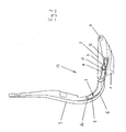
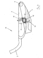
- FIG. 1 shows a schematic side view of a synchronous office chair with a support 1, a seat support 2 and a back part 3 at a Weglichn Trent of 0 °.
- Two of these three "main parts”, namely the seat support 2 and the back part 3 are movable in such a way that a synchronous movement is created.
- the FIG. 1 (as well as the FIG. 2 ) serve mainly to clarify the basic arrangement of the main parts, the carrier 1, the seat support 2 and the back part 3 for the purpose of representing their shape in the Figures 3-5 also shown in spatial representations.
- the carrier 1 is fixedly connected to a support column (not shown).
- the support column can be mounted in a manner customary for office chairs on an office chair foot part.
- the seat support 2 is articulated on a tilting axis 4.
- the seat support 2 has a rearwardly and upwardly toward the back part 3 extending horn 5.
- Seat support 2 and horn 5 are firmly connected.
- the back part 3 has a back bracket 6 extending downwards and toward the direction of the seat support 2.
- Back part 3 and back bar 6 are also firmly connected.
- the back bar 6 of the back part 3 engages in a space between the carrier 1 and the seat support 2, and the horn 5 of the seat support 2 engages in the back strap 6 a.
- the back yoke 6 has a first curved track 7, a second curved track 8, and a third curved track 9.
- the curved paths 7, 8, 9 are all approximately circular-arc-like and concave from the point of view of a viewer standing in front of and above the synchronous office chair.
- the second and third curved paths 8, 9 are brought together so closely from a lateral view (as shown here) that there is an overlap.
- a first roller bearing 10 is mounted, which engages in the first curved path 7 of the back yoke 6 and is guided in the synchronous movement of the office chair in the first curved path 7.
- a second roller bearing 11 is mounted, which engages in the second curved path 8 of the back yoke 6 and is guided in the synchronous movement of the office chair in the second curved path 8.
- a third roller bearing 12 is mounted, which engages in the third curved path 9 of the back bracket 6 and is guided in the synchronous movement of the office chair in the third curved path 9.
- the seat support 2 with the horn 5 makes a first tilting movement about the tilting axis 4.
- the back part 3 with the back yoke 6 makes a second tilting movement about a virtual axis 13 which is about two to three times as large as the first tilting movement.
- the back part 3 with the back bar 6 is still a translational movement down and forward.
- FIG. 2 shows a schematic side view of the synchronous office chair according Fig. 1 at a seat post inclination of 11 °.
- the back part 3 with the back bar 6 has made a sliding movement downwards and forwards and simultaneously also a rotational movement about the virtual axis 13.
- the instantaneous position of the virtual axis 13 is also shown here. It should be noted that the distance of the virtual axis 13 to the upper edge of the seat support 2 has barely changed.
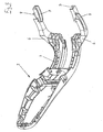
- FIG. 3 shows for clarity a spatial view of the carrier according to Fig. 1 , in the view from above and behind. Particularly clearly visible here is the third roller bearing 12th
- FIG. 4 shows for clarity a spatial view of the seat support according to Fig. 1 , in the view from above and in front.
- FIG. 5 shows for clarity a spatial view of the back according to Fig. 1 , in the view from the front and above. Particularly clearly visible here are first, second and third curved path 7,8,9.
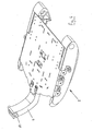
- FIG. 6 shows a schematic side view of the carrier 1 and the seat support 2 with the basic arrangement of the elements of the bias.
- the most important elements of the prestressing comprise at least one leaf spring 20, a support device 21, a support 22, a support surface 23 and a positioning device 24 for the support 22 on the support surface 23.
- the at least one leaf spring 20 is used to generate a biasing force for the bias and is fixed to a first leaf spring end 25 in the region of the tilting axis 4 on the carrier 1.
- the second (opposite) leaf spring end 26 is arranged vertically movable and resilient in the area below the rear middle part of the seat support 2.
- the seat support 2 is supported by means of the support means 21 attached thereto at the rear central part of the seat support 2 rolling or sliding on the / the leaf spring (s) or can be supported thereon.
- the at least one leaf spring 20 in turn is supported on the support surface 23 rolling or slidingly displaceable support 22.
- the positioning device 24 for the support 22 on the support surface 23 may be configured in various ways, but advantageously it is adjustable via a bevel gear 27 whose drive axis is arranged coaxially to the tilting axis 4.
- the at least one leaf spring 20 preferably consists of a glass fiber-plastic composite material with unidirectionally directed glass fibers.
- the strength values and the reliability of these (today common) materials are so good that can be realized with the disclosed leaf spring design preloads in a range of forces that can cover the entire range of application of very light to very heavy people.
- FIG. 7 shows for the sake of further clarification an exemption of the elements of the bias. Shown here is a bias with two parallel leaf springs 20, wherein the support means for the leaf springs 20 are formed here as a substantially cylindrical, slidable supports 22, and wherein the two supports 22 together by means of a shaft 28 and a threaded spindle 29 via the bevel gear 27th on the support surface 23 (see Fig. 6 ) can be slidably positioned.
- rolling supports could also be provided.
- FIG. 8 shows a spatial view of the carrier 1 with the elements of the bias voltage.
- plastic inserts 30 in which the leaf springs 20 at the first leaf spring ends 25th be held and fixed.
- the threaded spindle 29 via the bevel gear 27 is rotatable. Since the threaded spindle 29 is guided in a threaded hole of the shaft 28, by rotation on the crank 31, the position of the supports 22 on the bearing surface - and thus the biasing force for the bias - can be adjusted.
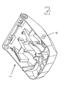
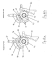
- FIG. 9 shows a schematic side view of the carrier 1 and the seat support 2 with the basic arrangement of the elements of the inclination stop.
- the most important elements of the inclination stop include a toothed segment 40 attached to the carrier 1 and a tilting mechanism holder 41 attached to the seat carrier 2.
- the tilting mechanism holder 41 in turn essentially contains a toothed wheel 42, a stop disc 43 and a ratchet lever 44 Tilting axis 4 moves the gear 42 on the sector gear 40 a certain way - here, of course, a circular arc segment - from.
- this path, or the circular arc segment is approximately 11 ° (angle degree) at a maximum when the inclination stop is fully released (deactivated).
- the gear 42 (in the present geometric conditions and because of the relatively narrow arc segment) when rolling on the sector gear 40 undergoes no complete revolution, it does not need to be provided with a toothing over the entire circumference.
- the activation / deactivation of the inclination stop is carried out via an actuation of the grid lever 44, which can be done for example by means of a push button via a cable.
- Other actuation mechanisms for example via linkage, are well known to those skilled in the art and of course, of course, may also be used.
- FIG. 10a shows a schematic representation of the elements of the inclination stop in the 0 ° position (the maximum inclination of the seat support 2 about the tilting axis 4 is here 0 °).
- the remaining parts of the synchronous office chair are omitted in this drawing.
- the inclination of the seat support 2 (not shown here) has a tilt angle of 0 ° (inclination about the tilting axis 4).
- the tilt stop is activated because the locking cam 50 of the grid lever 44 engages in the ratchet teeth 47 of the stop plate 43 and therefore prevents rotation of the stop plate 43. If a person sat down on the synchronous office chair, the gear 42 would go down in a counter-clockwise rotation on the toothed segment 40 when the tilt stop was not activated. This movement is blocked here but because of the abutting gear stop 45 and disc stop 46. The synchronous movement of the office chair is thus completely prevented here.
- the locking cam 50 of the grid lever 44 does not engage in the ratchet teeth 47 of the stop disc 43.
- the user of the synchronous office chair can recline with the tilt stop disabled, for example, up to a tilt of the seat support 2 by a tilt angle of 6 ° (inclination about the tilt axis 4), whereby the gear 42 and the stop plate 43 in the FIG. 10b reach shown position. If the user of the synchronous office chair decides that this position should be the maximum tilt position desired by him, he can in turn activate the inclination stop in this position, ie he can let snap the grid lever 44 with the locking cam 50 in this position again in the grid teeth 47 of the stop plate. This is so in the FIG. 10b shown.
- the Fig. 10b thus, finally shows a schematic representation of the elements of the inclination stop in the 6 ° position (the maximum inclination of the seat support 2 about the tilting axis 4 is here 6 °).
- the tilt stop is activated because the locking cam 50 of the grid lever 44 engages in the ratchet teeth 47 of the stop plate 43 and therefore prevents rotation of the stop plate 43.
- here is the tilting movement of the seat support 2 in the inclination range between 0 ° and 6 ° possible because the gear 42 and the stop plate 43 are at least partially mutually rotatable on the axis 48 are arranged.
- the disclosed inclination stop acts as a means for limiting the synchronous movement, ie the synchronous movement can be limited in one of the selectable rotational position of the stop disc 43 corresponding inclination position of the seat support 2 and the back part 3.
- the geometry and the design of the inventive tilt stop need not necessarily correspond exactly to the embodiment shown.
- the gear 42 with gear stopper 45 and the stopper plate 43 with the disc stopper 46 must not be made in one piece and neither the gear 42 nor the stopper plate 43 need only be provided on a part of its circumference with a toothing.
- both the device for the tilt stop as well as the device for the bias voltage are particularly suitable to be used in an office chair with a synchronous movement designed according to the invention.
- the inclination stop allows an optional and particularly easy-to-use limitation of the synchronous movement with simple means, while the bias is mainly due to the very large adjustment range, but certainly also because of the basic simplicity, well suited.
- the seat support 2 and the horn 5 are firmly connected together, as well as the back part 3 and the back bar 6.
- the corresponding parts it is structurally readily possible to make the corresponding parts either assemblable or in one piece.
Landscapes
- Health & Medical Sciences (AREA)
- Dentistry (AREA)
- General Health & Medical Sciences (AREA)
- Chairs Characterized By Structure (AREA)
- Chairs For Special Purposes, Such As Reclining Chairs (AREA)
- Exchange Systems With Centralized Control (AREA)
- Liquid Crystal Substances (AREA)
- Chair Legs, Seat Parts, And Backrests (AREA)
- Organic Low-Molecular-Weight Compounds And Preparation Thereof (AREA)
Abstract
Description
Die Erfindung betrifft einen Synchron-Bürostuhl nach Patentanspruch 1.The invention relates to a synchronous office chair according to claim 1.
Als Synchron-Bürostuhl bezeichnet man gängigerweise ein Sitzmöbel bei dem ein Sitzflächenteil und ein Rückenlehnenteil gekoppelte Bewegungen ausführen können. So kann ein derartiger Bürostuhl beispielsweise so ausgebildet sein, dass die Neigung des Rückenlehnenteils mit einer kleineren Neigung des Sitzflächenteils gekoppelt ist.As a synchronous office chair is commonly referred to a chair in which a seat part and a backrest part can perform coupled movements. For example, such an office chair can be designed so that the inclination of the backrest part is coupled with a smaller inclination of the seat surface part.
Die vorliegende Erfindung betrifft insbesondere einen Synchron-Bürostuhl mit im wesentlichen drei zum Zwecke der Erzeugung einer Synchronbewegung des Synchron-Bürostuhls zusammenwirkenden Hauptteilen. Diese drei Hauptteile sind auf einer Tragsäule angeordnet und umfassen einen mit der Tragsäule fest verbundenen Träger, einen am Träger an einer Kippachse angelenkten Sitzträger und ein Rückenteil, das an den Träger und den Sitzträger gekoppelt ist. Die Kippachse befindet sich dabei unter dem vorderen Bereich der Sitzfläche, also etwa im Kniebereich der sitzenden Person.More particularly, the present invention relates to a synchronous office chair having substantially three main parts cooperating to provide synchronous movement of the synchronous office chair. These three main parts are arranged on a support column and comprise a support fixedly connected to the support column, a seat support hinged to the support on a tilting axis and a back part which is coupled to the support and the seat support. The tilting axis is located under the front area of the seat, ie approximately in the knee area of the seated person.
Es sind zwar zahlreiche Synchron-Bürostühle bereits bekannt, die Synchron-Mechanismen aufweisen, so z.B. die
Aufgabe der Erfindung ist es, einen verbesserten Synchron-Bürostuhl anzugeben, bei dem der unerwünschte "pull-out"-Effekt weitgehend vermieden wird.The object of the invention is to provide an improved synchronous office chair, in which the undesirable "pull-out" effect is largely avoided.
Diese Aufgabe wird durch die Merkmalskombination des Patentanspruchs 1 gelöst.This object is achieved by the feature combination of claim 1.
Weiterhin sollen zudem auch eine in den verbesserten Synchron-Mechanismus gut integrierbare Vorrichtung zur Begrenzung der Synchronbewegung in der Form eines Neigungsanschlages und eine Vorrichtung zur Abbremsung der Synchronbewegung in der Form einer Vorspannung angegeben werden.Furthermore, also a well integrated in the improved synchronous mechanism device for limiting the synchronous movement in the form of an inclination stop and a device for decelerating the synchronous movement in the form of a bias voltage should be specified.
Ein erfindungsgemässer Synchron-Bürostuhl besteht deshalb im wesentlichen aus den folgenden Teilen:
- einem mit einer Tragsäule fest verbundenen Träger,
- einem am Träger an einer Kippachse angelenkten Sitzträger und einem mit dem Sitzträger fest verbundenen Horn,
- einem Rückenteil und einem mit dem Rückenteil fest verbundenen Rückenbügel, wobei der Rückenbügel
- -- eine erste Kurvenbahn,
- -- eine zweite Kurvenbahn, und
- -- eine dritte Kurvenbahn aufweist, und
- -- wobei der Rückenbügel des Rückenteils in einen Zwischenraum zwischen dem Träger und dem Sitzträger eingreift und wobei das Horn des Sitzträgers in den Rückenbügel eingreift,
- a support fixedly connected to a support column,
- a seat support hinged to the support on a tilt axis and a horn fixedly connected to the seat support,
- a back part and a backrest fixedly connected to the back part, wherein the back strap
- a first curved track,
- - a second curved path, and
- - Has a third curved path, and
- - Wherein the back strap of the back part engages in a space between the carrier and the seat carrier and wherein the horn of the seat carrier engages in the back strap,
Weiterhin ist beim erfindungsgemässen Synchron-Bürostuhl:
- am Horn des Sitzträgers ein erstes Rollenlager angebracht, das in die erste Kurvenbahn des Rückenbügels eingreift und bei der Synchronbewegung des Bürostuhls in der ersten Kurvenbahn geführt wird,
- am Sitzträger ein zweites Rollenlager angebracht, das in die zweite Kurvenbahn des Rückenbügels eingreift und bei der Synchronbewegung des Bürostuhls in der zweiten Kurvenbahn geführt wird,
- am Träger ein drittes Rollenlager angebracht, das in die dritte Kurvenbahn des Rückenbügels eingreift und bei der Synchronbewegung des Bürostuhls in der dritten Kurvenbahn geführt wird.
- attached to the horn of the seat carrier, a first roller bearing, which engages in the first curved path of the back bracket and is guided in the synchronous movement of the office chair in the first curved path,
- attached to the seat support a second roller bearing which engages in the second curved path of the back bracket and is guided in the synchronous movement of the office chair in the second curved path,
- attached to the carrier a third roller bearing, which engages in the third curved path of the back bracket and is guided in the synchronous movement of the office chair in the third curved path.
Die Synchronbewegung beim Synchron-Bürostuhl ist mittels der vorstehend genannten Teile derart ausgebildet, dass
- der Sitzträger mit dem Horn eine erste Kippbewegung um die Kippachse ausführt,
- das Rückenteil mit dem Rückenbügel eine zweite Kippbewegung um eine virtuelle Achse ausführt, die betragsmässig etwa zwei- bis dreimal so gross ist wie die erste Kippbewegung und gleichzeitig auch eine translatorische Bewegung ausführt,
- und zudem der momentane Drehpunkt der zweiten Kippbewegung um die virtuelle Achse im wesentlichen stets etwa im gleichen Abstand über dem hinteren mittleren Teil des Sitzträgers liegt.
- the seat support with the horn performs a first tilting movement about the tilting axis,
- the back part carries out a second tilting movement about a virtual axis with the back strap, which amount is approximately two to three times as large as the first tilting movement and at the same time also performs a translatory movement,
- and moreover, the instantaneous pivot point of the second tilting movement about the virtual axis is substantially always approximately the same distance above the rear central part of the seat support.
Die Vorteile dieser Lösung liegen insbesondere darin, dass auf komplizierte Hebelmechanismen verichtet werden kann und insbesondere das Hauptziel, nämlich die Vermeidung des "pull-out"-Effektes erreicht wird. Mit nur zwei beweglichen Hauptteilen, nämlich dem Sitzträger und dem Rückenteil, lässt sich dieses Ziel bereits erreichen.The advantages of this solution are, in particular, that it can be adapted to complex lever mechanisms and in particular the main goal, namely the avoidance of the "pull-out" effect is achieved. With only two main moving parts, namely the seat support and the back part, this goal can already be achieved.
Die Synchronbewegung, d.h. die zwangsgeführte Relativbewegung von Sitzträger und Rückenteil, wird durch die Führung der Rollenlager in den Kurvenbahnen erreicht. Die offenbarte Anordnung der Rollenlager und der Kurvenbahnen bewirkt, dass der momentane Drehpunkt der Kippbewegung des Rückenteils um die virtuelle Achse im wesentlichen stets etwa im gleichen Abstand über dem hinteren mittleren Teil des Sitzträgers zu liegen kommt. Bei einem auf dem Synchron-Bürostuhls sitzenden und sich zurücklehnenden Menschen bleibt somit der Körperdrehpunkt und der momentane Drehpunkt der Kippbewegung des Rückenteils um die virtuelle Achse in weitgehender Übereinstimmung, was zum angestrebten Ziel führt.The synchronous movement, i. the positively driven relative movement of seat support and back part is achieved by the leadership of the roller bearings in the curved paths. The disclosed arrangement of the roller bearings and the cam tracks causes the instantaneous pivot point of the tilting movement of the back part about the virtual axis to be essentially always approximately the same distance above the rear central part of the seat carrier. Thus, in a human seated and reclining on the synchronous office chair, the body pivot point and the instantaneous pivot point of the back rest tilting about the virtual axis are largely in agreement, resulting in the desired goal.
Wie bereits erwähnt, kann der verbesserte Synchron-Mechanismus auch gut mit einer Vorrichtung zur Abbremsung der Synchronbewegung - nämlich in der Form einer Vorspannung - kombiniert werden. Hier besteht das Ziel darin, eine verstellbare Abfederung des Sitzträgers und des Rückenteils zu erreichen, die sowohl für sehr leichte wie auch für sehr schwere Personen optimal geeignet und einstellbar ist, und die zudem auch über eine sehr hohe Zuverlässigkeit und Lebensdauer verfügt. Durch den Einsatz von Blattfedern mit verschiebbarem Auflager sowie der Verwendung eines Kegelradantriebs zur Verschiebung bzw. Positionierung der Auflager erreicht man nicht nur einen einfachen mechanischen Aufbau sondern auch die gewünschte Anwendungsbreite.As already mentioned, the improved synchronous mechanism can also be well combined with a device for slowing down the synchronous movement - namely in the form of a bias voltage. Here, the goal is to achieve an adjustable cushioning of the seat support and the back part, which is optimally suitable and adjustable for very light as well as for very heavy people, and also has a very high reliability and durability. Through the use of leaf springs with sliding support and the use of a bevel gear for shifting or positioning of the supports not only achieves a simple mechanical structure but also the desired scope of application.
Es hat sich nämlich gezeigt, dass insbesondere Blattfedern aus einem Glasfaser-Kunststoffverbundmaterial mit unidirektional gerichteten Glasfasern die notwendigen Festigkeitswerte und insbesondere auch die gewünschte Lebensdauer erbringen. Andere Materialien, wie Stahlfedern und dergleichen neigen hingegen sehr viel schneller zu Ermüdungsbrüchen und können zudem in der Regel auch nicht für die gesamte Anwendungsbreite von sehr leichten bis sehr schweren Personen geeignet dimensioniert werden.In fact, it has been found that in particular leaf springs made of a glass fiber plastic composite material with unidirectionally directed glass fibers provide the necessary strength values and in particular the desired service life. Other materials, such as steel springs and the like, on the other hand, tend to break fatigue much more quickly and, moreover, can not usually be used for the entire range of applications from very light to very heavy Persons are suitably dimensioned.
Wie ebenfalls bereits erwähnt, kann der verbesserte Synchron-Mechanismus weiterhin auch gut mit einer Vorrichtung zur Begrenzung der Synchronbewegung - hier in der Form eines Neigungsanschlages - kombiniert werden. Der Benützer des erfindungsgemässen Synchron-Bürostuhls soll in einfacher Weise die maximale Neigung des Rückenteils bzw. des Sitzträgers einstellen und verändern können. Durch den Einsatz eines Zahnsegmentes am Träger sowie eines Zahnrad mit einer Anschlagscheibe und einem Rasterhebel in einer Neigungsmechanikhalterung am Sitzträger sowie einer Betätigungsvorrichtung zur Betätigung des Rasterhebels erreicht man auch hier den angestrebten einfachen und zuverlässigen mechanischen Aufbau. Die erwähnten Elemente zur Realisierung des Neigungsanschlages bewirken letztlich, dass das Zahnrad, das auf dem Zahnsegment läuft - je nach Einstellung des Neigungsanschlages - lediglich einen bestimmten Weg auf dem ganzen zum Verfügung stehenden Weg auf dem Zahnsegment abfahren kann. Bei nicht eingeklinktem Rasterhebel in der Anschlagscheibe kann der ganze zur Verfügung stehende Weg auf dem Zahnsegment ausgenützt werden. Der Benützer kann also, beispielsweise mittels eines Druckknopfes über einen Kabelzug, den Rasterhebel von der Anschlagscheibe lösen und den Synchron-Bürostuhl in eine beliebige Neigeposition (innerhalb des gesamten möglichen Bereiches der Synchronbewegung) nach hinten kippen um sich eine neue Anschlagposition auszusuchen. Somit ergibt sich auch hier eine sehr einfache und zweckmässige Bedienbarkeit.As already mentioned, the improved synchronous mechanism can also be combined well with a device for limiting the synchronous movement - here in the form of a tilt stop. The user of the synchronous office chair according to the invention should be able to adjust and change the maximum inclination of the back part or of the seat support in a simple manner. Through the use of a toothed segment on the support and a gear with a stop disc and a grid lever in a tilting mechanism holder on the seat support and an actuator for actuating the grid lever can be achieved here the desired simple and reliable mechanical structure. The mentioned elements for realizing the inclination stop ultimately cause the gear that runs on the toothed segment - depending on the setting of the inclination stop - can only depart a certain way on the whole available path on the sector gear. If the locking lever is not engaged in the stop disc, the entire available path on the toothed segment can be utilized. The user can therefore, for example by means of a push button on a cable, solve the grid lever of the stop disc and tilt the synchronous office chair in any tilt position (within the entire possible range of synchronous movement) to the rear to pick a new stop position. Thus, here too results in a very simple and convenient operation.
Im Folgenden wird ein Ausführungsbeispiel eines erfindungsgemässen Bürostuhls anhand von Zeichnungen näher erläutert.In the following, an embodiment of an inventive office chair will be explained in more detail with reference to drawings.
In den Zeichnungen zeigen:
- Fig. 1
- eine schematische Seitenansicht eines SynchronBürostuhls mit einem Träger, einem Sitzträger und einem Rückenteil bei einer Sitzträgerneigung von 0°,
- Fig. 2
- eine schematische Seitenansicht des Synchron-Bürostuhls gemäss
Fig. 1 bei einer Sitzträgerneigung von 11°, - Fig. 3
- eine räumliche Ansicht des Trägers gemäss
Fig. 1 von oben, - Fig. 4
- eine räumliche Ansicht des Sitzträgers gemäss
Fig. 1 von oben, - Fig. 5
- eine räumliche Ansicht des Rückenteils gemäss
Fig. 1 von vorne, - Fig. 6
- eine schematische Seitenansicht des Trägers und des Sitzträgers mit der prinzipiellen Anordnung der Elemente der Vorspannung,
- Fig. 7
- eine Freistellung der Elemente der Vorspannung,
- Fig. 8
- eine räumliche Ansicht des Trägers mit den Elementen der Vorspannung,
- Fig. 9
- eine schematische Seitenansicht des Trägers und des Sitzträgers mit der prinzipiellen Anordnung der Elemente des Neigungsanschlages,
- Fig. 10a
- eine schematische Darstellung der Elemente des Neigungsanschlages in
der 0°-Position, und - Fig. 10b
- eine schematische Darstellung der Elemente des Neigungsanschlages in
der 6°-Position.
- Fig. 1
- a schematic side view of a synchronous office chair with a carrier, a seat support and a back at a Sitzträgernigung of 0 °,
- Fig. 2
- a schematic side view of the synchronous office chair according
Fig. 1 at a seat post inclination of 11 °, - Fig. 3
- a spatial view of the carrier according to
Fig. 1 from above, - Fig. 4
- a spatial view of the seat support according
Fig. 1 from above, - Fig. 5
- a spatial view of the back according to
Fig. 1 from the front, - Fig. 6
- a schematic side view of the carrier and the seat carrier with the basic arrangement of the elements of the bias voltage,
- Fig. 7
- an exemption of the elements of the prestress,
- Fig. 8
- a spatial view of the carrier with the elements of the bias,
- Fig. 9
- a schematic side view of the carrier and the seat support with the basic arrangement of the elements of the inclination stop,
- Fig. 10a
- a schematic representation of the elements of the tilt stop in the 0 ° position, and
- Fig. 10b
- a schematic representation of the elements of the tilt stop in the 6 ° position.
Die
Der Träger 1 ist mit einer Tragsäule (nicht dargestellt) fest verbundenen. Die Tragsäule kann dabei in einer für Bürostühle üblichen Weise an einem Bürostuhl-Fussteil angebracht sein. Am Träger 1 ist an einer Kippachse 4 der Sitzträger 2 angelenkt. Der Sitzträger 2 weist ein sich nach hinten und oben Richtung Rückenteil 3 erstreckendes Horn 5 auf. Sitzträger 2 und Horn 5 sind fest miteinander verbunden. Das Rückenteil 3 weist einen sich nach unten und vorn Richtung Sitzträger 2 erstreckenden Rückenbügel 6 auf. Rückenteil 3 und Rückenbügel 6 sind ebenfalls fest miteinander verbunden. Der Rückenbügel 6 des Rückenteils 3 greift dabei in einen Zwischenraum zwischen dem Träger 1 und dem Sitzträger 2 ein, und das Horn 5 des Sitzträgers 2 greift in den Rückenbügel 6 ein.
Der Rückenbügel 6 weist eine erste Kurvenbahn 7, eine zweite Kurvenbahn 8, und eine dritte Kurvenbahn 9 auf.The carrier 1 is fixedly connected to a support column (not shown). The support column can be mounted in a manner customary for office chairs on an office chair foot part. On the support 1, the
The
Die Kurvenbahnen 7,8,9 sind dabei alle näherungsweise kreisbogenartig und aus der Sichtweise eines Betrachters, der vor und über dem Synchron-Bürostuhl steht, konkav. Zudem sind die zweite und dritte Kurvenbahn 8,9 aus seitlicher Ansicht (wie hier gezeigt) so nahe zusammengerückt, dass eine Überlappung besteht.The
Am Horn 5 des Sitzträgers 2 ist ein erstes Rollenlager 10 angebracht, das in die erste Kurvenbahn 7 des Rückenbügels 6 eingreift und bei der Synchronbewegung des Bürostuhls in der ersten Kurvenbahn 7 geführt wird.At the
Am Sitzträger 2 ist ein zweites Rollenlager 11 angebracht, das in die zweite Kurvenbahn 8 des Rückenbügels 6 eingreift und bei der Synchronbewegung des Bürostuhls in der zweiten Kurvenbahn 8 geführt wird.On the
Am Träger 1 ist ein drittes Rollenlager 12 angebracht, das in die dritte Kurvenbahn 9 des Rückenbügels 6 eingreift und bei der Synchronbewegung des Bürostuhls in der dritten Kurvenbahn 9 geführt wird.On the carrier 1, a
Wenn sich nun ein Benützer auf den Synchron-Bürostuhl setzt und zurücklehnt, so führen der Sitzträger 2 und das Rückenteil 3 die erwähnte Synchronbewegung aus. Der Sitzträger 2 mit dem Horn 5 macht eine erste Kippbewegung um die Kippachse 4. Das Rückenteil 3 mit dem Rückenbügel 6 macht eine zweite Kippbewegung um eine virtuelle Achse 13, die betragsmässig etwa zwei- bis dreimal so gross ist wie die erste Kippbewegung. Gleichzeitig macht das Rückenteil 3 mit dem Rückenbügel 6 noch eine translatorische Bewegung nach unten und vorne. Während der Synchronbewegung bleibt der momentane Drehpunkt der zweiten Kippbewegung um die virtuelle Achse 13 im wesentlichen stets etwa im gleichen Abstand über dem hinteren mittleren Teil des Sitzträgers. Dies ist aus den
Die Eigenschaft des erfindungsgemässen Synchron-Bürostuhls, dass während der Synchronbewegung der momentane Drehpunkt der zweiten Kippbewegung um die virtuelle Achse 13 im wesentlichen stets etwa im gleichen Abstand über dem hinteren mittleren Teil des Sitzträgers bleibt, ist beabsichtigt und wird durch die gezeigten Aufbau der Synchron-Mechanik, insbesondere der Anordung der Kurvenbahnen 7,8,9 und der Rollenlager 10,11,12 erreicht. Sie bewirkt, dass der eingangs erwähnte "pull-out"-Effekt nicht eintritt oder doch zumindest sehr stark minimiert wird.The property of the synchronous office chair according to the invention that during the synchronous movement the instantaneous pivot point of the second tilting movement about the
Die
Man beachte auch, dass hier (auch in Bezug auf
Die
Die
Die
Die
Die mindestens eine Blattfeder 20 dient zur Erzeugung einer Vorspannkraft für die Vorspannung und ist an einem ersten Blattfederende 25 im Bereich der Kippachse 4 am Träger 1 fixiert. Das zweite (gegenüberliegende) Blattfederende 26 ist im Bereich unter dem hinteren mittleren Teil des Sitzträgers 2 vertikal beweglich und federnd angeordnet. Der Sitzträger 2 ist mittels der daran befestigten Abstützeinrichtung 21 am hinteren mittleren Teil des Sitzträgers 2 rollend oder gleitend auf der/den Blattfeder(n) abgestützt oder darauf abstützbar. Die mindestens eine Blattfeder 20 stützt sich ihrerseits auf das auf der Auflagefläche 23 rollend oder gleitend verschiebbare Auflager 22. Somit lässt sich durch Verschiebung bzw. Positionierung des Auflagers 22 auf der Auflagefläche 23 die Vorspannkraft für die Vorspannung - also die der ersten Kippbewegung des Sitzträgers 2 entgegenwirkende Kraft - stufenlos einstellen.The at least one
Die Positionierungsvorrichtung 24 für das Auflager 22 auf der Auflagefläche 23 kann verschiedenartig ausgestaltet sein, vorteilhafterweise ist sie aber über einen Kegelradantrieb 27 einstellbar, dessen Antriebsachse koaxial zur Kippachse 4 angeordnet ist.The
Die mindestens eine Blattfeder 20 besteht dabei vorzugsweise aus einem Glasfaser-Kunststoffverbundmaterial mit unidirektional gerichteten Glasfasern. Die Festigkeitswerte und die Zuverlässigkeit dieser (heute gängigen) Materialien sind so gut, dass sich mit der offenbarten Blattfederkonstruktion Vorspannungen in einem Kräftebereich realisieren lassen, die den gesamten Anwendungsbereich von sehr leichten bis zu sehr schweren Personen abdecken können.The at least one
Die
Die
Die
Der Aufbau und die Wirkungsweise des Neigungsanschlags wird anhand der
Die
Die Teile in der Neigungsmechanikhalterung 41, also das Zahnrad 42, die Anschlagscheibe 43 und der Rasterhebel sind in diesem Ausführungsbeispiel wie folgt aufgebaut:
Das Zahnrad 42, weist einen Zahnradanschlag 45 auf. Wie bereits erwähnt, braucht das Zahnrad nicht über den ganzen Umfang verzahnt zu sein.Der Zahnradanschlag 45 wird hier durch eine Flanke eines ersten Zahnradzahnes gebildet, es kann aber auch ein separater, mit dem Zahnrad fest verbundener Zahnradanschlag vorhanden sein.- die
Anschlagscheibe 43 weist einen Scheibenanschlag 46 auf.Der Scheibenanschlag 46 ist zur Anlage bzw.Anschlag am Zahnradanschlag 45 ausgestaltet.Die Anschlagscheibe 43 weist zudem entlang ihres Umfangs eineReihe von Rasterzähnen 47 auf. Auch hier brauchen die Rasterzähne nicht auf dem gesamten Umfang der Anschlagscheibe vorhanden zu sein und auch hier könnte ein separater Scheibenanschlag vorgesehen sein. das Zahnrad 42 und dieAnschlagscheibe 43 sind koaxial und zumindest teilweise gegenseitig verdrehbar auf einer Achse 48 inder Neigungsmechanikhalterung 41, die ihrerseits amSitzträger 2 angebracht ist, gelagert. Die nur zumindest teilweise mögliche gegenseitige Verdrehbarkeit ergibt sich,wenn der Zahnradanschlag 45 und der Scheibenanschlag 46 gegenseitig in Anschlag stehen (was hier der Fall ist).der Rasterhebel 44 ist an einer Schwenkachse 49 in der Neigungsmechanikhalterung gelagert und greiftmit einem Arretiernocken 50 indie Rasterzähne 47 des Scheibenanschlages 46 ein.Der Rasterhebel 44 ist mittels eines (nicht dargestellten) Seilzuges über eine Oese 51 betätigbar.
- The
gear 42 has agear stop 45. As already mentioned, the gear need not be toothed over the entire circumference. Thegear stop 45 is formed here by an edge of a first gear tooth, but it may also be a separate, fixed to the gear gear stopper be present. - the
stop disc 43 has adisc stop 46. Thedisc stop 46 is designed for abutment or stop on thegear stop 45. Thestop disc 43 also has along its circumference a series ofraster teeth 47. Again, the grid teeth do not need to be present on the entire circumference of the stop plate and also here a separate disc stop could be provided. - the
gear 42 and thestopper plate 43 are coaxial and at least partially mutually rotatable on anaxis 48 in thetilting mechanism mount 41, which in turn is mounted on theseat support 2, stored. The only at least partially possible mutual rotatability results when thegear stopper 45 and thedisc stop 46 are mutually abutting (which is the case here). - the
grid lever 44 is mounted on a pivot axis 49 in the inclination mechanism holder and engages with a lockingcam 50 in thegrid teeth 47 of the disc stop 46 a. Thegrid lever 44 can be actuated by means of a cable (not shown) via aneyelet 51.
In der
Im Gegensatz zum vorstehend beschriebenen Zustand greift beim deaktiviertem Neigungsanschlag der Arretiernocken 50 des Rasterhebels 44 nicht in die Rasterzähne 47 der Anschlagscheibe 43 ein. Somit kann der Benützer des Synchron-Bürostuhls sich bei deaktiviertem Neigungsanschlag zurücklehnen, beispielsweise bis zu einer Neigung des Sitzträgers 2 um einen Kippwinkel von 6° (Neigung um die Kippachse 4), wodurch das Zahnrad 42 und die Anschlagscheibe 43 die in der
Die
Selbstverständlich müssen die Geometrie und die Ausgestaltung des erfindungsgemässen Neigungsanschlages nicht notwendigerweise genau dem gezeigten Ausführungsbeispiel entsprechen. So müssen beispielsweise das Zahnrad 42 mit Zahnradanschlag 45 und die Anschlagscheibe 43 mit dem Scheibenanschlag 46 nicht einteilig ausgeführt sein und weder das Zahnrad 42 noch die Anschlagscheibe 43 müssen nur an einem Teil ihres Umfanges mit einer Verzahnung versehen sein.Of course, the geometry and the design of the inventive tilt stop need not necessarily correspond exactly to the embodiment shown. For example, the
Insgesamt sind sowohl die Vorrichtung für den Neigungsanschlag wie auch die Vorrichtung für die Vorspannung besonders geeignet um in einem Bürostuhl mit einer erfindungsgemäss ausgestalteten Synchronbewegung eingesetzt zu werden. Der Neigungsanschlag erlaubt eine wahlfreie und besonders einfach bedienbare Begrenzung der Synchronbewegung mit einfachen Mitteln, während die Vorspannung hauptsächlich wegen des sehr grossen Einstellbereiches, sicher aber auch wegen der prinzipiellen Einfachheit, gut geeignet ist.Overall, both the device for the tilt stop as well as the device for the bias voltage are particularly suitable to be used in an office chair with a synchronous movement designed according to the invention. The inclination stop allows an optional and particularly easy-to-use limitation of the synchronous movement with simple means, while the bias is mainly due to the very large adjustment range, but certainly also because of the basic simplicity, well suited.
Wie bereits früher erwähnt, sind im dargestellten Ausführungsbeispiel der Sitzträger 2 und das Horn 5 fest miteinander verbunden, ebenso das Rückenteil 3 und der Rückenbügel 6. Selbstverständlich ist es konstruktiv ohne weiteres möglich, die entsprechenden Teile entweder zusammenbaubar oder einstückig zu gestalten.As mentioned earlier, in the illustrated embodiment, the
- 11
- Trägercarrier
- 22
- Sitzträgerseat support
- 33
- Rückenteilback
- 44
- Kippachsetilt axis
- 55
- Hornhorn
- 66
- Rückenbügelback support
- 77
- 1. Kurvenbahn1st curved track
- 88th
- 2. Kurvenbahn2nd curved path
- 99
- 3. Kurvenbahn3rd curved path
- 1010
- 1. Rollenlager1. Roller bearings
- 1111
- 2. Rollenlager2. Roller bearings
- 1212
- 3. Rollenlager3. Roller bearings
- 1313
- virtuelle Achsevirtual axis
- 14-1914-19
- nicht verwendetnot used
- 2020
- Blattfederleaf spring
- 2121
- Abstützeinrichtungsupport means
- 2222
- AuflagerIn stock
- 2323
- Auflageflächebearing surface
- 2424
- Positionierungsvorrichtung (für das Auflager)Positioning device (for the support)
- 2525
- 1. Blattfederende1. leaf spring end
- 2626
- 2. Blattfederende2nd leaf spring end
- 2727
- Kegelradantriebbevel gear
- 2828
- Wellewave
- 2929
- Gewindespindelscrew
- 3030
- KunststoffeinlagePlastic insert
- 3131
- Kurbelcrank
- 32-3932-39
- nicht verwendetnot used
- 4040
- Zahnradsegmentgear segment
- 4141
- NeigungsmechanikhalterungInclination mechanism holder
- 4242
- Zahnradgear
- 4343
- Anschlagscheibestop disc
- 4444
- Rasterhebelgrid lever
- 4545
- Zahnradanschlaggear stop
- 4646
- Scheibenanschlagglass-stop
- 4747
- Rasterzähnegrid teeth
- 4848
- Achseaxis
- 4949
- Schwenkachseswivel axis
- 5050
- Arretiernockenlocking boss
- 5151
- OeseEyelet
Claims (7)
- Synchronised office chair, having- a support (1) rigidly connected to a support column,- a seat support (2) hinge-jointed to the support (1) on a tilting axle (4), and a horn (5) that is rigidly connected to the seat support (2),- a back part (3) and a back frame (6), wherein the back frame (6) has- a first curved track (7),- a second curved track (8), and- a third curved track (9), and- wherein the back frame (6) of the back part (3) engages in a cavity between the support (1) and the seat support (2) and wherein the horn (5) of the seat support (3) engages in the back frame (6),and wherein the seat support (2) with the horn (5) and the back part (3) with the back frame (6) are constructed for executing a synchronised motion, and where additionally in said synchronised office chair- a first roller bearing (10) is mounted on the horn (5), which engages in the first curved track (7) of the back frame (6) and during the synchronised motion of the office chair is guided in the first curved track (7),- a second roller bearing (11) is mounted on the seat support (2), which engages in the second curved track (8) of the back frame (6) and during the synchronised motion of the office chair is guided in the second curved track (8),- a third roller bearing (12) is mounted on the support (1), which engages in the third curved track (9) of the back frame (6) and during the synchronised motion of the office chair is guided in the third curved track (9),and the synchronised motion of the synchronised office chair is configured in such a way that- said seat support (2) executes a first tilting movement with the horn (5) about the tilting axle (4),- said back part (3) executes a second tilting movement with the back frame (6) about a virtual axis (13), which in extent is about twice or three times as large as the first tilting movement, and simultaneously also executes a translational movement,- and in addition the instantaneous fulcrum of the second tilting movement about the virtual axis (13) is always substantially at about the same distance above the rear central part of the seat support (2).
- Synchronised office chair according to Claim 1, characterized in that a device for limiting the synchronised motion in the form of a reclining stop is present, and/or a device for slowing down the synchronised motion in the form of a pretension is present.
- Synchronised office chair according to Claim 2, characterized in that at least one leaf spring (20) is mounted on the support (1) for applying a pre-tensioning force for the pretension, wherein- the at least one leaf spring (20) is fixed at a first leaf spring end (25) in the region of the tilting axle (4) on the support (1), and at a second leaf spring end (26) is arranged in a moveable and elastic manner in the region below the rear central part of the seat support (2), and- said seat support (2) is or can be supported by means of a support device (21) on the rear central part of the seat support (2), rolling or sliding on the leaf spring (20), andwherein a support (22), displaceable in a rolling or sliding manner on a support surface (23), is present, on which the at least one leaf spring (20) is supported and wherein the pre-tensioning force can be adjusted by displacement of the support (22) on the support surface (23).
- Synchronised office chair according to Claim 3, characterized in that the positioning of the support (22) is adjustable by means of a conical gear drive (27).
- Synchronised office chair according to Claim 3 or 4, characterized in that the at least one leaf spring (20) consists of a fibreglass-plastic composite material with unidirectionally aligned glass fibres.
- Synchronised office chair according to Claim 2, characterized in that a toothed segment (40) is mounted on the base (1) and a cog (42) with a stop plate (43) and a locking lever (44) are mounted on the seat support (2) in a reclining mechanism support (41), wherein- said cog (42) engages in the toothed segment (40) and can be moved up and down during the synchronised motion,- the cog (42) comprises a cog stop (45),- the stop plate (43) comprises a plate stop (46),- the cog (42) and the stop plate (43) are mounted coaxially on an axle (48) and are at least partially mutually rotatable, and- the stop plate (43) can be locked by means of the locking lever (44) in a selectable rotary position with respect to the reclining mechanism support (41),wherein the synchronised motion can be limited in a reclining position of the seat support (2), or of the back part (3), corresponding to the selectable rotary position of the stop plate (43) in which the cog stop (45) and the plate stop (46) are mutually limited.
- Synchronised office chair according to Claim 6, characterized in that said locking lever (44) can be detached, or disengaged, from the stop plate (43) by means of an activation device and in the reclining position of the seat support (2), or of the back part (3), corresponding to the selectable rotary position of the stop plate can be reengaged into the stop plate (43).
Applications Claiming Priority (1)
| Application Number | Priority Date | Filing Date | Title |
|---|---|---|---|
| CH16002006 | 2006-10-06 |
Publications (2)
| Publication Number | Publication Date |
|---|---|
| EP1908374A1 EP1908374A1 (en) | 2008-04-09 |
| EP1908374B1 true EP1908374B1 (en) | 2009-02-11 |
Family
ID=38050193
Family Applications (1)
| Application Number | Title | Priority Date | Filing Date |
|---|---|---|---|
| EP07405286A Active EP1908374B1 (en) | 2006-10-06 | 2007-09-26 | Synchronous office chair |
Country Status (8)
| Country | Link |
|---|---|
| US (1) | US7513569B2 (en) |
| EP (1) | EP1908374B1 (en) |
| JP (1) | JP2008093447A (en) |
| AT (1) | ATE422315T1 (en) |
| BR (1) | BRPI0704231B8 (en) |
| DE (1) | DE502007000434D1 (en) |
| ES (1) | ES2322301T3 (en) |
| PT (1) | PT1908374E (en) |
Families Citing this family (23)
| Publication number | Priority date | Publication date | Assignee | Title |
|---|---|---|---|---|
| AR057387A1 (en) * | 2005-06-20 | 2007-12-05 | Humanscale Corp | SEAT APPLIANCE WITH RECLINING MOVEMENT |
| GB0708053D0 (en) | 2007-04-26 | 2007-06-06 | Leuven | Adjustable furniture |
| DE202008006179U1 (en) * | 2008-05-06 | 2008-07-17 | Design Ballendat Gmbh | Chair with swiveling backrest |
| US20100141002A1 (en) * | 2008-06-04 | 2010-06-10 | Kurrasch Andrew J | Biasing mechanism |
| DE102009050903B4 (en) * | 2009-10-27 | 2014-02-13 | Siemens Aktiengesellschaft | vehicle seat |
| DE102009052111B4 (en) | 2009-11-05 | 2012-05-16 | Johnson Controls Gmbh | Seat cushion tilt adjustment |
| GB201014953D0 (en) | 2010-09-08 | 2010-10-20 | Birkbeck Hilary R | Slide chair action |
| GB201015414D0 (en) | 2010-09-15 | 2010-10-27 | Birkbeck Hilary R | Link chair action |
| EP2739183B1 (en) * | 2011-08-04 | 2017-10-04 | Cramer LLC | Ergonomic seating assemblies and methods |
| US9504326B1 (en) | 2012-04-10 | 2016-11-29 | Humanscale Corporation | Reclining chair |
| USD697726S1 (en) | 2012-09-20 | 2014-01-21 | Steelcase Inc. | Chair |
| US11304528B2 (en) | 2012-09-20 | 2022-04-19 | Steelcase Inc. | Chair assembly with upholstery covering |
| WO2014163581A1 (en) * | 2013-04-05 | 2014-10-09 | Singapore Technologies Aerospace Ltd | Seat structure for a passenger seat and passenger seat |
| EP2981190B1 (en) * | 2013-04-05 | 2021-11-17 | St Engineering Aerospace Ltd. | Passenger seat for an aircraft |
| US11596235B2 (en) | 2015-02-11 | 2023-03-07 | Aaron DeJule | Apparatus with weight responsive changeable adjusting characteristics |
| JP6840675B2 (en) | 2015-03-14 | 2021-03-10 | ハーマン、ミラー、インコーポレイテッドHerman Miller Incorporated | A mechanical assembly for a chair and a chair with that mechanical assembly |
| DE102017105398A1 (en) | 2016-03-14 | 2017-09-14 | Burkhard Schmitz | chair |
| DE102016104638A1 (en) | 2016-03-14 | 2017-09-14 | Burkhard Schmitz | chair |
| JP7107902B2 (en) * | 2019-02-26 | 2022-07-27 | トヨタ自動車株式会社 | vehicle seat |
| EP3702209B1 (en) | 2019-02-26 | 2023-06-21 | Toyota Jidosha Kabushiki Kaisha | Vehicle seat |
| US12089741B2 (en) * | 2019-06-17 | 2024-09-17 | Quali Co., Ltd. | Tiltable chair |
| NL2026485B1 (en) | 2020-09-16 | 2022-05-16 | Npk Design B V | Adjustable chair |
| US11812870B2 (en) | 2021-02-10 | 2023-11-14 | Steelcase Inc. | Body support structure |
Family Cites Families (19)
| Publication number | Priority date | Publication date | Assignee | Title |
|---|---|---|---|---|
| FR1596508A (en) * | 1968-07-18 | 1970-06-22 | ||
| BR8203375A (en) * | 1981-06-15 | 1983-05-31 | Budd Co | SPRING SHEET FOR SUSPENSION OF RECIPOUS STRUCTURES AND THE PROCESS OF ITS MANUFACTURING |
| JPH0436675Y2 (en) * | 1986-04-03 | 1992-08-28 | ||
| NL8601457A (en) * | 1986-06-05 | 1988-01-04 | Huka Bv Developments | WHEELCHAIR WITH TILT SEAT. |
| US5058954A (en) * | 1988-07-07 | 1991-10-22 | Kan Chee Lee | Body contour support structure for travelers and audiences |
| JPH0520199Y2 (en) * | 1988-11-30 | 1993-05-26 | ||
| JPH0779742B2 (en) * | 1989-07-27 | 1995-08-30 | 株式会社イトーキクレビオ | Chair tilting device |
| DE4135948C2 (en) * | 1991-10-31 | 1993-12-23 | Rolf Voelkle | Chair, in particular office swivel chair |
| EP0726723B1 (en) * | 1993-11-01 | 1998-11-25 | Labofa A/S | A working chair with synchronous seat and back adjustment |
| US5558399A (en) * | 1994-09-13 | 1996-09-24 | Serber; Hector | Seat and lumbar motion chair, assembly and method |
| NO300754B1 (en) * | 1994-10-14 | 1997-07-21 | Handicare Ind As | Adjustable chair |
| GB9500022D0 (en) * | 1995-01-04 | 1995-03-01 | Unwalla Jamshed | Integrated seat and back and mechanism for chairs |
| JPH0998849A (en) * | 1995-10-03 | 1997-04-15 | Minerva:Kk | Tilting device for chair |
| US6106065A (en) * | 1997-10-24 | 2000-08-22 | Reliance Medical Products, Inc. | Examination chair with lifting and tilting mechanism |
| IT1306152B1 (en) * | 1999-06-02 | 2001-05-30 | Aviointeriors Spa | ARMCHAIR WITH PERFECTED CRADLE MOVEMENT, IN PARTICULAR AIRCRAFT. |
| US6607244B2 (en) * | 2001-04-02 | 2003-08-19 | Edward L. Stulik | Reclining chair |
| DE10122946C1 (en) * | 2001-05-11 | 2003-01-30 | Armin Sander | Chair, especially office chair |
| US7090240B2 (en) * | 2002-10-28 | 2006-08-15 | Plainsense Wheelchairs, Inc. | Tiltable seating apparatus for wheelchair |
| US7073860B2 (en) * | 2003-07-07 | 2006-07-11 | Isidoro Natalio Markus | Reclinable chair mechanism |
-
2007
- 2007-09-26 EP EP07405286A patent/EP1908374B1/en active Active
- 2007-09-26 AT AT07405286T patent/ATE422315T1/en not_active IP Right Cessation
- 2007-09-26 DE DE502007000434T patent/DE502007000434D1/en active Active
- 2007-09-26 ES ES07405286T patent/ES2322301T3/en active Active
- 2007-09-26 PT PT07405286T patent/PT1908374E/en unknown
- 2007-10-01 BR BRPI0704231A patent/BRPI0704231B8/en not_active IP Right Cessation
- 2007-10-05 US US11/973,231 patent/US7513569B2/en not_active Expired - Fee Related
- 2007-10-09 JP JP2007263480A patent/JP2008093447A/en active Pending
Also Published As
| Publication number | Publication date |
|---|---|
| JP2008093447A (en) | 2008-04-24 |
| BRPI0704231B1 (en) | 2018-01-30 |
| DE502007000434D1 (en) | 2009-03-26 |
| PT1908374E (en) | 2009-05-18 |
| ES2322301T3 (en) | 2009-06-18 |
| ATE422315T1 (en) | 2009-02-15 |
| US7513569B2 (en) | 2009-04-07 |
| US20080084100A1 (en) | 2008-04-10 |
| BRPI0704231B8 (en) | 2018-02-27 |
| EP1908374A1 (en) | 2008-04-09 |
| BRPI0704231A (en) | 2008-05-27 |
Similar Documents
| Publication | Publication Date | Title |
|---|---|---|
| EP1908374B1 (en) | Synchronous office chair | |
| DE19853156B4 (en) | Seat | |
| DE69600110T2 (en) | Improvements to the adjustment and operating devices of moving and deformable parts of an office chair | |
| EP1454568B1 (en) | Chair, particularly office-chair | |
| DE102006047889B4 (en) | Seating furniture, in particular office chair | |
| EP3965617B1 (en) | Seating furniture having dual-motor wall-away function | |
| DE1779707A1 (en) | Armchair or similar seating furniture with adjustment device | |
| DE2724725A1 (en) | SEAT | |
| CH661647A5 (en) | Chair | |
| DE2541559A1 (en) | Adjustable lumbar support for seat - has two arm linkage to seat frame for vertical and horizontal movement | |
| DE10306851A1 (en) | Office chair has back rest which reclines about axis at ends of L-shaped levers mounted on its base, seat sliding forward in synchronization with back rest and axis maintaining constant position above seat | |
| DE69208275T2 (en) | Mechanical device, in particular for moving and selectively locking chairs | |
| DE69306938T2 (en) | CHAIR | |
| EP0537542A1 (en) | Chair control for adjusting seats and backrests of chairs, especially office chairs | |
| EP2046165A1 (en) | Seating | |
| DE69607655T2 (en) | DEVICE FOR ADJUSTING THE TILTING ANGLE IN GENERAL | |
| WO2006136400A1 (en) | Armrest for a vehicle seat and corresponding vehicle seat | |
| DE10123231C2 (en) | office chair | |
| EP2989931B1 (en) | Seating | |
| DE19528649C2 (en) | Chair with backrest reset | |
| DE102016209121A1 (en) | seat device | |
| WO2010028412A1 (en) | Device for adjusting the pivoting resistance of a backrest | |
| DE1265367B (en) | Adjustable armchair | |
| DE19900454C2 (en) | Chair, especially office chair | |
| DE10103569B4 (en) | Office chair with armrests |
Legal Events
| Date | Code | Title | Description |
|---|---|---|---|
| PUAI | Public reference made under article 153(3) epc to a published international application that has entered the european phase |
Free format text: ORIGINAL CODE: 0009012 |
|
| AK | Designated contracting states |
Kind code of ref document: A1 Designated state(s): AT BE BG CH CY CZ DE DK EE ES FI FR GB GR HU IE IS IT LI LT LU LV MC MT NL PL PT RO SE SI SK TR |
|
| AX | Request for extension of the european patent |
Extension state: AL BA HR MK RS |
|
| 17P | Request for examination filed |
Effective date: 20080611 |
|
| GRAP | Despatch of communication of intention to grant a patent |
Free format text: ORIGINAL CODE: EPIDOSNIGR1 |
|
| AKX | Designation fees paid |
Designated state(s): AT BE BG CH CY CZ DE DK EE ES FI FR GB GR HU IE IS IT LI LT LU LV MC MT NL PL PT RO SE SI SK TR |
|
| GRAS | Grant fee paid |
Free format text: ORIGINAL CODE: EPIDOSNIGR3 |
|
| GRAA | (expected) grant |
Free format text: ORIGINAL CODE: 0009210 |
|
| AK | Designated contracting states |
Kind code of ref document: B1 Designated state(s): AT BE BG CH CY CZ DE DK EE ES FI FR GB GR HU IE IS IT LI LT LU LV MC MT NL PL PT RO SE SI SK TR |
|
| REG | Reference to a national code |
Ref country code: GB Ref legal event code: FG4D Free format text: NOT ENGLISH |
|
| REG | Reference to a national code |
Ref country code: CH Ref legal event code: EP |
|
| REG | Reference to a national code |
Ref country code: IE Ref legal event code: FG4D Free format text: LANGUAGE OF EP DOCUMENT: GERMAN |
|
| REF | Corresponds to: |
Ref document number: 502007000434 Country of ref document: DE Date of ref document: 20090326 Kind code of ref document: P |
|
| REG | Reference to a national code |
Ref country code: CH Ref legal event code: NV Representative=s name: R. A. EGLI & CO. PATENTANWAELTE |
|
| REG | Reference to a national code |
Ref country code: PT Ref legal event code: SC4A Free format text: AVAILABILITY OF NATIONAL TRANSLATION Effective date: 20090511 |
|
| REG | Reference to a national code |
Ref country code: GR Ref legal event code: EP Ref document number: 20090401260 Country of ref document: GR |
|
| REG | Reference to a national code |
Ref country code: ES Ref legal event code: FG2A Ref document number: 2322301 Country of ref document: ES Kind code of ref document: T3 |
|
| PG25 | Lapsed in a contracting state [announced via postgrant information from national office to epo] |
Ref country code: SI Free format text: LAPSE BECAUSE OF FAILURE TO SUBMIT A TRANSLATION OF THE DESCRIPTION OR TO PAY THE FEE WITHIN THE PRESCRIBED TIME-LIMIT Effective date: 20090211 Ref country code: FI Free format text: LAPSE BECAUSE OF FAILURE TO SUBMIT A TRANSLATION OF THE DESCRIPTION OR TO PAY THE FEE WITHIN THE PRESCRIBED TIME-LIMIT Effective date: 20090211 Ref country code: LT Free format text: LAPSE BECAUSE OF FAILURE TO SUBMIT A TRANSLATION OF THE DESCRIPTION OR TO PAY THE FEE WITHIN THE PRESCRIBED TIME-LIMIT Effective date: 20090211 |
|
| PG25 | Lapsed in a contracting state [announced via postgrant information from national office to epo] |
Ref country code: PL Free format text: LAPSE BECAUSE OF FAILURE TO SUBMIT A TRANSLATION OF THE DESCRIPTION OR TO PAY THE FEE WITHIN THE PRESCRIBED TIME-LIMIT Effective date: 20090211 Ref country code: LV Free format text: LAPSE BECAUSE OF FAILURE TO SUBMIT A TRANSLATION OF THE DESCRIPTION OR TO PAY THE FEE WITHIN THE PRESCRIBED TIME-LIMIT Effective date: 20090211 Ref country code: IS Free format text: LAPSE BECAUSE OF FAILURE TO SUBMIT A TRANSLATION OF THE DESCRIPTION OR TO PAY THE FEE WITHIN THE PRESCRIBED TIME-LIMIT Effective date: 20090611 Ref country code: SE Free format text: LAPSE BECAUSE OF FAILURE TO SUBMIT A TRANSLATION OF THE DESCRIPTION OR TO PAY THE FEE WITHIN THE PRESCRIBED TIME-LIMIT Effective date: 20090511 |
|
| REG | Reference to a national code |
Ref country code: IE Ref legal event code: FD4D |
|
| PG25 | Lapsed in a contracting state [announced via postgrant information from national office to epo] |
Ref country code: IE Free format text: LAPSE BECAUSE OF FAILURE TO SUBMIT A TRANSLATION OF THE DESCRIPTION OR TO PAY THE FEE WITHIN THE PRESCRIBED TIME-LIMIT Effective date: 20090211 Ref country code: DK Free format text: LAPSE BECAUSE OF FAILURE TO SUBMIT A TRANSLATION OF THE DESCRIPTION OR TO PAY THE FEE WITHIN THE PRESCRIBED TIME-LIMIT Effective date: 20090211 Ref country code: EE Free format text: LAPSE BECAUSE OF FAILURE TO SUBMIT A TRANSLATION OF THE DESCRIPTION OR TO PAY THE FEE WITHIN THE PRESCRIBED TIME-LIMIT Effective date: 20090211 Ref country code: CZ Free format text: LAPSE BECAUSE OF FAILURE TO SUBMIT A TRANSLATION OF THE DESCRIPTION OR TO PAY THE FEE WITHIN THE PRESCRIBED TIME-LIMIT Effective date: 20090211 |
|
| PG25 | Lapsed in a contracting state [announced via postgrant information from national office to epo] |
Ref country code: SK Free format text: LAPSE BECAUSE OF FAILURE TO SUBMIT A TRANSLATION OF THE DESCRIPTION OR TO PAY THE FEE WITHIN THE PRESCRIBED TIME-LIMIT Effective date: 20090211 Ref country code: RO Free format text: LAPSE BECAUSE OF FAILURE TO SUBMIT A TRANSLATION OF THE DESCRIPTION OR TO PAY THE FEE WITHIN THE PRESCRIBED TIME-LIMIT Effective date: 20090211 |
|
| PLBE | No opposition filed within time limit |
Free format text: ORIGINAL CODE: 0009261 |
|
| STAA | Information on the status of an ep patent application or granted ep patent |
Free format text: STATUS: NO OPPOSITION FILED WITHIN TIME LIMIT |
|
| 26N | No opposition filed |
Effective date: 20091112 |
|
| PG25 | Lapsed in a contracting state [announced via postgrant information from national office to epo] |
Ref country code: BG Free format text: LAPSE BECAUSE OF FAILURE TO SUBMIT A TRANSLATION OF THE DESCRIPTION OR TO PAY THE FEE WITHIN THE PRESCRIBED TIME-LIMIT Effective date: 20090511 |
|
| PG25 | Lapsed in a contracting state [announced via postgrant information from national office to epo] |
Ref country code: MC Free format text: LAPSE BECAUSE OF NON-PAYMENT OF DUE FEES Effective date: 20090930 |
|
| PG25 | Lapsed in a contracting state [announced via postgrant information from national office to epo] |
Ref country code: AT Free format text: LAPSE BECAUSE OF NON-PAYMENT OF DUE FEES Effective date: 20090926 |
|
| PG25 | Lapsed in a contracting state [announced via postgrant information from national office to epo] |
Ref country code: LU Free format text: LAPSE BECAUSE OF NON-PAYMENT OF DUE FEES Effective date: 20090926 |
|
| PG25 | Lapsed in a contracting state [announced via postgrant information from national office to epo] |
Ref country code: HU Free format text: LAPSE BECAUSE OF FAILURE TO SUBMIT A TRANSLATION OF THE DESCRIPTION OR TO PAY THE FEE WITHIN THE PRESCRIBED TIME-LIMIT Effective date: 20090812 |
|
| PG25 | Lapsed in a contracting state [announced via postgrant information from national office to epo] |
Ref country code: TR Free format text: LAPSE BECAUSE OF FAILURE TO SUBMIT A TRANSLATION OF THE DESCRIPTION OR TO PAY THE FEE WITHIN THE PRESCRIBED TIME-LIMIT Effective date: 20090211 |
|
| PG25 | Lapsed in a contracting state [announced via postgrant information from national office to epo] |
Ref country code: CY Free format text: LAPSE BECAUSE OF FAILURE TO SUBMIT A TRANSLATION OF THE DESCRIPTION OR TO PAY THE FEE WITHIN THE PRESCRIBED TIME-LIMIT Effective date: 20090211 |
|
| PGFP | Annual fee paid to national office [announced via postgrant information from national office to epo] |
Ref country code: PT Payment date: 20110921 Year of fee payment: 5 Ref country code: GR Payment date: 20110923 Year of fee payment: 5 |
|
| PGFP | Annual fee paid to national office [announced via postgrant information from national office to epo] |
Ref country code: GB Payment date: 20120920 Year of fee payment: 6 |
|
| PGFP | Annual fee paid to national office [announced via postgrant information from national office to epo] |
Ref country code: ES Payment date: 20120919 Year of fee payment: 6 |
|
| PGFP | Annual fee paid to national office [announced via postgrant information from national office to epo] |
Ref country code: FR Payment date: 20121010 Year of fee payment: 6 Ref country code: BE Payment date: 20120920 Year of fee payment: 6 Ref country code: NL Payment date: 20120920 Year of fee payment: 6 |
|
| PGFP | Annual fee paid to national office [announced via postgrant information from national office to epo] |
Ref country code: IT Payment date: 20120925 Year of fee payment: 6 |
|
| REG | Reference to a national code |
Ref country code: PT Ref legal event code: MM4A Free format text: LAPSE DUE TO NON-PAYMENT OF FEES Effective date: 20130326 |
|
| REG | Reference to a national code |
Ref country code: GR Ref legal event code: ML Ref document number: 20090401260 Country of ref document: GR Effective date: 20130404 |
|
| PG25 | Lapsed in a contracting state [announced via postgrant information from national office to epo] |
Ref country code: PT Free format text: LAPSE BECAUSE OF NON-PAYMENT OF DUE FEES Effective date: 20130326 |
|
| PG25 | Lapsed in a contracting state [announced via postgrant information from national office to epo] |
Ref country code: GR Free format text: LAPSE BECAUSE OF NON-PAYMENT OF DUE FEES Effective date: 20130404 |
|
| BERE | Be: lapsed |
Owner name: STOLL GIROFLEX A.G. Effective date: 20130930 |
|
| REG | Reference to a national code |
Ref country code: NL Ref legal event code: V1 Effective date: 20140401 |
|
| GBPC | Gb: european patent ceased through non-payment of renewal fee |
Effective date: 20130926 |
|
| REG | Reference to a national code |
Ref country code: FR Ref legal event code: ST Effective date: 20140530 |
|
| PG25 | Lapsed in a contracting state [announced via postgrant information from national office to epo] |
Ref country code: GB Free format text: LAPSE BECAUSE OF NON-PAYMENT OF DUE FEES Effective date: 20130926 Ref country code: BE Free format text: LAPSE BECAUSE OF NON-PAYMENT OF DUE FEES Effective date: 20130930 |
|
| PG25 | Lapsed in a contracting state [announced via postgrant information from national office to epo] |
Ref country code: NL Free format text: LAPSE BECAUSE OF NON-PAYMENT OF DUE FEES Effective date: 20140401 Ref country code: IT Free format text: LAPSE BECAUSE OF NON-PAYMENT OF DUE FEES Effective date: 20130926 Ref country code: FR Free format text: LAPSE BECAUSE OF NON-PAYMENT OF DUE FEES Effective date: 20130930 |
|
| REG | Reference to a national code |
Ref country code: ES Ref legal event code: FD2A Effective date: 20141007 |
|
| PG25 | Lapsed in a contracting state [announced via postgrant information from national office to epo] |
Ref country code: ES Free format text: LAPSE BECAUSE OF NON-PAYMENT OF DUE FEES Effective date: 20130927 |
|
| REG | Reference to a national code |
Ref country code: DE Ref legal event code: R082 Ref document number: 502007000434 Country of ref document: DE Representative=s name: HUMBOLDT-PATENT HUEBNER NEUMANN RADWER WENZEL, DE |
|
| PGFP | Annual fee paid to national office [announced via postgrant information from national office to epo] |
Ref country code: DE Payment date: 20170928 Year of fee payment: 11 |
|
| PGFP | Annual fee paid to national office [announced via postgrant information from national office to epo] |
Ref country code: CH Payment date: 20171227 Year of fee payment: 11 |
|
| REG | Reference to a national code |
Ref country code: DE Ref legal event code: R119 Ref document number: 502007000434 Country of ref document: DE |
|
| REG | Reference to a national code |
Ref country code: CH Ref legal event code: PL |
|
| PG25 | Lapsed in a contracting state [announced via postgrant information from national office to epo] |
Ref country code: DE Free format text: LAPSE BECAUSE OF NON-PAYMENT OF DUE FEES Effective date: 20190402 |
|
| PG25 | Lapsed in a contracting state [announced via postgrant information from national office to epo] |
Ref country code: CH Free format text: LAPSE BECAUSE OF NON-PAYMENT OF DUE FEES Effective date: 20180930 Ref country code: LI Free format text: LAPSE BECAUSE OF NON-PAYMENT OF DUE FEES Effective date: 20180930 |