EP1905992A1 - Verfahren zur steuerung eines abgasreinigungsystems und abgasreinigungssystem - Google Patents
Verfahren zur steuerung eines abgasreinigungsystems und abgasreinigungssystem Download PDFInfo
- Publication number
- EP1905992A1 EP1905992A1 EP06767011A EP06767011A EP1905992A1 EP 1905992 A1 EP1905992 A1 EP 1905992A1 EP 06767011 A EP06767011 A EP 06767011A EP 06767011 A EP06767011 A EP 06767011A EP 1905992 A1 EP1905992 A1 EP 1905992A1
- Authority
- EP
- European Patent Office
- Prior art keywords
- exhaust gas
- control
- regeneration
- gas temperature
- temperature raising
- Prior art date
- Legal status (The legal status is an assumption and is not a legal conclusion. Google has not performed a legal analysis and makes no representation as to the accuracy of the status listed.)
- Granted
Links
- 238000000746 purification Methods 0.000 title claims abstract description 61
- 238000000034 method Methods 0.000 title claims description 18
- 238000002347 injection Methods 0.000 claims abstract description 93
- 239000007924 injection Substances 0.000 claims abstract description 93
- 238000002485 combustion reaction Methods 0.000 claims abstract description 21
- 230000008929 regeneration Effects 0.000 claims description 133
- 238000011069 regeneration method Methods 0.000 claims description 133
- 239000003054 catalyst Substances 0.000 claims description 67
- 238000007254 oxidation reaction Methods 0.000 claims description 34
- 230000003647 oxidation Effects 0.000 claims description 33
- 239000000446 fuel Substances 0.000 claims description 20
- 238000011144 upstream manufacturing Methods 0.000 claims description 20
- 239000000779 smoke Substances 0.000 abstract description 18
- 238000011084 recovery Methods 0.000 abstract description 3
- 239000007789 gas Substances 0.000 description 203
- 239000013618 particulate matter Substances 0.000 description 35
- 238000001514 detection method Methods 0.000 description 10
- 238000004519 manufacturing process Methods 0.000 description 8
- 230000008859 change Effects 0.000 description 6
- 230000009467 reduction Effects 0.000 description 6
- BASFCYQUMIYNBI-UHFFFAOYSA-N platinum Chemical compound [Pt] BASFCYQUMIYNBI-UHFFFAOYSA-N 0.000 description 5
- QVGXLLKOCUKJST-UHFFFAOYSA-N atomic oxygen Chemical compound [O] QVGXLLKOCUKJST-UHFFFAOYSA-N 0.000 description 4
- 230000003111 delayed effect Effects 0.000 description 4
- 238000010586 diagram Methods 0.000 description 4
- 229910052760 oxygen Inorganic materials 0.000 description 4
- 239000001301 oxygen Substances 0.000 description 4
- 238000009825 accumulation Methods 0.000 description 3
- 230000004913 activation Effects 0.000 description 3
- 239000000919 ceramic Substances 0.000 description 3
- 230000003247 decreasing effect Effects 0.000 description 3
- 238000001704 evaporation Methods 0.000 description 3
- 230000008020 evaporation Effects 0.000 description 3
- NINIDFKCEFEMDL-UHFFFAOYSA-N Sulfur Chemical compound [S] NINIDFKCEFEMDL-UHFFFAOYSA-N 0.000 description 2
- 230000000694 effects Effects 0.000 description 2
- 239000012784 inorganic fiber Substances 0.000 description 2
- 239000010705 motor oil Substances 0.000 description 2
- 239000003921 oil Substances 0.000 description 2
- 230000001590 oxidative effect Effects 0.000 description 2
- 229910052717 sulfur Inorganic materials 0.000 description 2
- 239000011593 sulfur Substances 0.000 description 2
- PNEYBMLMFCGWSK-UHFFFAOYSA-N aluminium oxide Inorganic materials [O-2].[O-2].[O-2].[Al+3].[Al+3] PNEYBMLMFCGWSK-UHFFFAOYSA-N 0.000 description 1
- 229910000420 cerium oxide Inorganic materials 0.000 description 1
- 238000006243 chemical reaction Methods 0.000 description 1
- 230000006835 compression Effects 0.000 description 1
- 238000007906 compression Methods 0.000 description 1
- 239000002826 coolant Substances 0.000 description 1
- 238000010790 dilution Methods 0.000 description 1
- 239000012895 dilution Substances 0.000 description 1
- 238000005516 engineering process Methods 0.000 description 1
- 239000000835 fiber Substances 0.000 description 1
- 230000008018 melting Effects 0.000 description 1
- 238000002844 melting Methods 0.000 description 1
- 238000012544 monitoring process Methods 0.000 description 1
- BMMGVYCKOGBVEV-UHFFFAOYSA-N oxo(oxoceriooxy)cerium Chemical compound [Ce]=O.O=[Ce]=O BMMGVYCKOGBVEV-UHFFFAOYSA-N 0.000 description 1
- 229910052697 platinum Inorganic materials 0.000 description 1
- 229910003446 platinum oxide Inorganic materials 0.000 description 1
- 231100000572 poisoning Toxicity 0.000 description 1
- 230000000607 poisoning effect Effects 0.000 description 1
- 230000008569 process Effects 0.000 description 1
- 238000010926 purge Methods 0.000 description 1
- 230000009257 reactivity Effects 0.000 description 1
Images


Classifications
-
- F—MECHANICAL ENGINEERING; LIGHTING; HEATING; WEAPONS; BLASTING
- F02—COMBUSTION ENGINES; HOT-GAS OR COMBUSTION-PRODUCT ENGINE PLANTS
- F02D—CONTROLLING COMBUSTION ENGINES
- F02D41/00—Electrical control of supply of combustible mixture or its constituents
- F02D41/02—Circuit arrangements for generating control signals
- F02D41/021—Introducing corrections for particular conditions exterior to the engine
- F02D41/0235—Introducing corrections for particular conditions exterior to the engine in relation with the state of the exhaust gas treating apparatus
- F02D41/027—Introducing corrections for particular conditions exterior to the engine in relation with the state of the exhaust gas treating apparatus to purge or regenerate the exhaust gas treating apparatus
- F02D41/029—Introducing corrections for particular conditions exterior to the engine in relation with the state of the exhaust gas treating apparatus to purge or regenerate the exhaust gas treating apparatus the exhaust gas treating apparatus being a particulate filter
-
- B—PERFORMING OPERATIONS; TRANSPORTING
- B01—PHYSICAL OR CHEMICAL PROCESSES OR APPARATUS IN GENERAL
- B01D—SEPARATION
- B01D53/00—Separation of gases or vapours; Recovering vapours of volatile solvents from gases; Chemical or biological purification of waste gases, e.g. engine exhaust gases, smoke, fumes, flue gases, aerosols
- B01D53/34—Chemical or biological purification of waste gases
- B01D53/92—Chemical or biological purification of waste gases of engine exhaust gases
- B01D53/94—Chemical or biological purification of waste gases of engine exhaust gases by catalytic processes
- B01D53/9495—Controlling the catalytic process
-
- F—MECHANICAL ENGINEERING; LIGHTING; HEATING; WEAPONS; BLASTING
- F01—MACHINES OR ENGINES IN GENERAL; ENGINE PLANTS IN GENERAL; STEAM ENGINES
- F01N—GAS-FLOW SILENCERS OR EXHAUST APPARATUS FOR MACHINES OR ENGINES IN GENERAL; GAS-FLOW SILENCERS OR EXHAUST APPARATUS FOR INTERNAL COMBUSTION ENGINES
- F01N11/00—Monitoring or diagnostic devices for exhaust-gas treatment apparatus, e.g. for catalytic activity
- F01N11/002—Monitoring or diagnostic devices for exhaust-gas treatment apparatus, e.g. for catalytic activity the diagnostic devices measuring or estimating temperature or pressure in, or downstream of the exhaust apparatus
-
- F—MECHANICAL ENGINEERING; LIGHTING; HEATING; WEAPONS; BLASTING
- F01—MACHINES OR ENGINES IN GENERAL; ENGINE PLANTS IN GENERAL; STEAM ENGINES
- F01N—GAS-FLOW SILENCERS OR EXHAUST APPARATUS FOR MACHINES OR ENGINES IN GENERAL; GAS-FLOW SILENCERS OR EXHAUST APPARATUS FOR INTERNAL COMBUSTION ENGINES
- F01N3/00—Exhaust or silencing apparatus having means for purifying, rendering innocuous, or otherwise treating exhaust
- F01N3/02—Exhaust or silencing apparatus having means for purifying, rendering innocuous, or otherwise treating exhaust for cooling, or for removing solid constituents of, exhaust
- F01N3/021—Exhaust or silencing apparatus having means for purifying, rendering innocuous, or otherwise treating exhaust for cooling, or for removing solid constituents of, exhaust by means of filters
- F01N3/023—Exhaust or silencing apparatus having means for purifying, rendering innocuous, or otherwise treating exhaust for cooling, or for removing solid constituents of, exhaust by means of filters using means for regenerating the filters, e.g. by burning trapped particles
- F01N3/0235—Exhaust or silencing apparatus having means for purifying, rendering innocuous, or otherwise treating exhaust for cooling, or for removing solid constituents of, exhaust by means of filters using means for regenerating the filters, e.g. by burning trapped particles using exhaust gas throttling means
-
- F—MECHANICAL ENGINEERING; LIGHTING; HEATING; WEAPONS; BLASTING
- F01—MACHINES OR ENGINES IN GENERAL; ENGINE PLANTS IN GENERAL; STEAM ENGINES
- F01N—GAS-FLOW SILENCERS OR EXHAUST APPARATUS FOR MACHINES OR ENGINES IN GENERAL; GAS-FLOW SILENCERS OR EXHAUST APPARATUS FOR INTERNAL COMBUSTION ENGINES
- F01N3/00—Exhaust or silencing apparatus having means for purifying, rendering innocuous, or otherwise treating exhaust
- F01N3/02—Exhaust or silencing apparatus having means for purifying, rendering innocuous, or otherwise treating exhaust for cooling, or for removing solid constituents of, exhaust
- F01N3/021—Exhaust or silencing apparatus having means for purifying, rendering innocuous, or otherwise treating exhaust for cooling, or for removing solid constituents of, exhaust by means of filters
- F01N3/033—Exhaust or silencing apparatus having means for purifying, rendering innocuous, or otherwise treating exhaust for cooling, or for removing solid constituents of, exhaust by means of filters in combination with other devices
- F01N3/035—Exhaust or silencing apparatus having means for purifying, rendering innocuous, or otherwise treating exhaust for cooling, or for removing solid constituents of, exhaust by means of filters in combination with other devices with catalytic reactors, e.g. catalysed diesel particulate filters
-
- F—MECHANICAL ENGINEERING; LIGHTING; HEATING; WEAPONS; BLASTING
- F01—MACHINES OR ENGINES IN GENERAL; ENGINE PLANTS IN GENERAL; STEAM ENGINES
- F01N—GAS-FLOW SILENCERS OR EXHAUST APPARATUS FOR MACHINES OR ENGINES IN GENERAL; GAS-FLOW SILENCERS OR EXHAUST APPARATUS FOR INTERNAL COMBUSTION ENGINES
- F01N3/00—Exhaust or silencing apparatus having means for purifying, rendering innocuous, or otherwise treating exhaust
- F01N3/08—Exhaust or silencing apparatus having means for purifying, rendering innocuous, or otherwise treating exhaust for rendering innocuous
- F01N3/10—Exhaust or silencing apparatus having means for purifying, rendering innocuous, or otherwise treating exhaust for rendering innocuous by thermal or catalytic conversion of noxious components of exhaust
- F01N3/105—General auxiliary catalysts, e.g. upstream or downstream of the main catalyst
- F01N3/106—Auxiliary oxidation catalysts
-
- F—MECHANICAL ENGINEERING; LIGHTING; HEATING; WEAPONS; BLASTING
- F02—COMBUSTION ENGINES; HOT-GAS OR COMBUSTION-PRODUCT ENGINE PLANTS
- F02D—CONTROLLING COMBUSTION ENGINES
- F02D41/00—Electrical control of supply of combustible mixture or its constituents
- F02D41/02—Circuit arrangements for generating control signals
- F02D41/021—Introducing corrections for particular conditions exterior to the engine
- F02D41/0235—Introducing corrections for particular conditions exterior to the engine in relation with the state of the exhaust gas treating apparatus
- F02D41/024—Introducing corrections for particular conditions exterior to the engine in relation with the state of the exhaust gas treating apparatus to increase temperature of the exhaust gas treating apparatus
-
- F—MECHANICAL ENGINEERING; LIGHTING; HEATING; WEAPONS; BLASTING
- F02—COMBUSTION ENGINES; HOT-GAS OR COMBUSTION-PRODUCT ENGINE PLANTS
- F02D—CONTROLLING COMBUSTION ENGINES
- F02D41/00—Electrical control of supply of combustible mixture or its constituents
- F02D41/30—Controlling fuel injection
- F02D41/38—Controlling fuel injection of the high pressure type
- F02D41/40—Controlling fuel injection of the high pressure type with means for controlling injection timing or duration
- F02D41/402—Multiple injections
- F02D41/405—Multiple injections with post injections
-
- F—MECHANICAL ENGINEERING; LIGHTING; HEATING; WEAPONS; BLASTING
- F02—COMBUSTION ENGINES; HOT-GAS OR COMBUSTION-PRODUCT ENGINE PLANTS
- F02D—CONTROLLING COMBUSTION ENGINES
- F02D9/00—Controlling engines by throttling air or fuel-and-air induction conduits or exhaust conduits
- F02D9/04—Controlling engines by throttling air or fuel-and-air induction conduits or exhaust conduits concerning exhaust conduits
- F02D9/06—Exhaust brakes
-
- B—PERFORMING OPERATIONS; TRANSPORTING
- B01—PHYSICAL OR CHEMICAL PROCESSES OR APPARATUS IN GENERAL
- B01D—SEPARATION
- B01D2251/00—Reactants
- B01D2251/20—Reductants
- B01D2251/208—Hydrocarbons
-
- B—PERFORMING OPERATIONS; TRANSPORTING
- B01—PHYSICAL OR CHEMICAL PROCESSES OR APPARATUS IN GENERAL
- B01D—SEPARATION
- B01D2258/00—Sources of waste gases
- B01D2258/01—Engine exhaust gases
- B01D2258/012—Diesel engines and lean burn gasoline engines
-
- F—MECHANICAL ENGINEERING; LIGHTING; HEATING; WEAPONS; BLASTING
- F02—COMBUSTION ENGINES; HOT-GAS OR COMBUSTION-PRODUCT ENGINE PLANTS
- F02B—INTERNAL-COMBUSTION PISTON ENGINES; COMBUSTION ENGINES IN GENERAL
- F02B23/00—Other engines characterised by special shape or construction of combustion chambers to improve operation
- F02B23/08—Other engines characterised by special shape or construction of combustion chambers to improve operation with positive ignition
- F02B2023/085—Other engines characterised by special shape or construction of combustion chambers to improve operation with positive ignition using several spark plugs per cylinder
-
- F—MECHANICAL ENGINEERING; LIGHTING; HEATING; WEAPONS; BLASTING
- F02—COMBUSTION ENGINES; HOT-GAS OR COMBUSTION-PRODUCT ENGINE PLANTS
- F02D—CONTROLLING COMBUSTION ENGINES
- F02D2200/00—Input parameters for engine control
- F02D2200/60—Input parameters for engine control said parameters being related to the driver demands or status
- F02D2200/604—Engine control mode selected by driver, e.g. to manually start particle filter regeneration or to select driving style
-
- F—MECHANICAL ENGINEERING; LIGHTING; HEATING; WEAPONS; BLASTING
- F02—COMBUSTION ENGINES; HOT-GAS OR COMBUSTION-PRODUCT ENGINE PLANTS
- F02D—CONTROLLING COMBUSTION ENGINES
- F02D2250/00—Engine control related to specific problems or objectives
- F02D2250/38—Control for minimising smoke emissions, e.g. by applying smoke limitations on the fuel injection amount
-
- F—MECHANICAL ENGINEERING; LIGHTING; HEATING; WEAPONS; BLASTING
- F02—COMBUSTION ENGINES; HOT-GAS OR COMBUSTION-PRODUCT ENGINE PLANTS
- F02D—CONTROLLING COMBUSTION ENGINES
- F02D41/00—Electrical control of supply of combustible mixture or its constituents
- F02D41/02—Circuit arrangements for generating control signals
- F02D41/14—Introducing closed-loop corrections
- F02D41/1438—Introducing closed-loop corrections using means for determining characteristics of the combustion gases; Sensors therefor
- F02D41/1444—Introducing closed-loop corrections using means for determining characteristics of the combustion gases; Sensors therefor characterised by the characteristics of the combustion gases
- F02D41/1446—Introducing closed-loop corrections using means for determining characteristics of the combustion gases; Sensors therefor characterised by the characteristics of the combustion gases the characteristics being exhaust temperatures
-
- F—MECHANICAL ENGINEERING; LIGHTING; HEATING; WEAPONS; BLASTING
- F02—COMBUSTION ENGINES; HOT-GAS OR COMBUSTION-PRODUCT ENGINE PLANTS
- F02D—CONTROLLING COMBUSTION ENGINES
- F02D41/00—Electrical control of supply of combustible mixture or its constituents
- F02D41/30—Controlling fuel injection
- F02D41/38—Controlling fuel injection of the high pressure type
- F02D41/40—Controlling fuel injection of the high pressure type with means for controlling injection timing or duration
- F02D41/402—Multiple injections
-
- Y—GENERAL TAGGING OF NEW TECHNOLOGICAL DEVELOPMENTS; GENERAL TAGGING OF CROSS-SECTIONAL TECHNOLOGIES SPANNING OVER SEVERAL SECTIONS OF THE IPC; TECHNICAL SUBJECTS COVERED BY FORMER USPC CROSS-REFERENCE ART COLLECTIONS [XRACs] AND DIGESTS
- Y02—TECHNOLOGIES OR APPLICATIONS FOR MITIGATION OR ADAPTATION AGAINST CLIMATE CHANGE
- Y02T—CLIMATE CHANGE MITIGATION TECHNOLOGIES RELATED TO TRANSPORTATION
- Y02T10/00—Road transport of goods or passengers
- Y02T10/10—Internal combustion engine [ICE] based vehicles
- Y02T10/12—Improving ICE efficiencies
-
- Y—GENERAL TAGGING OF NEW TECHNOLOGICAL DEVELOPMENTS; GENERAL TAGGING OF CROSS-SECTIONAL TECHNOLOGIES SPANNING OVER SEVERAL SECTIONS OF THE IPC; TECHNICAL SUBJECTS COVERED BY FORMER USPC CROSS-REFERENCE ART COLLECTIONS [XRACs] AND DIGESTS
- Y02—TECHNOLOGIES OR APPLICATIONS FOR MITIGATION OR ADAPTATION AGAINST CLIMATE CHANGE
- Y02T—CLIMATE CHANGE MITIGATION TECHNOLOGIES RELATED TO TRANSPORTATION
- Y02T10/00—Road transport of goods or passengers
- Y02T10/10—Internal combustion engine [ICE] based vehicles
- Y02T10/40—Engine management systems
Definitions
- the present invention relates to a method of controlling an exhaust gas purification system and an exhaust gas purification system that performs a regeneration control including both an exhaust gas temperature raising control not performing post injection and an exhaust gas temperature raising control performing post injection in order to recover the purification ability of an exhaust gas purifier to purify components in the exhaust gas of an internal combustion engine of a diesel engine, etc.
- PM particulate matter
- DPF diesel particulate filter
- a regeneration control (referred to as PM regeneration control) is performed in which the collected PM is burned and removed forcibly by raising the exhaust gas temperature forcibly when clogging of the filter exceeds a predetermined amount.
- PM regeneration control a regeneration control
- the methods of detecting the clogging of this filter for example, there is a method of detecting by a pressure difference between the upstream side and the downstream side of the filter, and a method of detecting by obtaining a PM accumulated amount by calculating the PM amount collected in an operation state of the engine from map data set in advance, etc.
- the exhaust gas temperature raising control is performed in this PM regeneration control.
- this exhaust gas temperature raising control in the case where the exhaust gas temperature is lower than the active temperature of an oxidation catalyst provided upstream of the filter or an oxidation catalyst carried by the filter, the temperature of the exhaust gas flowing into the filter is raised to the temperature at which the PM collected by the filter burns or more by performing the exhaust gas temperature raising control. Thereby, the filter is regenerated by raising the filter temperature and by burning and removing PM.
- the exhaust gas temperature raising control there is a method of performing a multiple injection (multiple-stage delayed injection) and a post injection (after-injection) as in-cylinder fuel injections.
- This multiple injection is a multiple-stage delayed injection performed to raise the exhaust gas temperature to the active temperature of the oxidation catalyst or more.
- the post injection is performed to increase HC in the exhaust gas, the HC burns with the oxidation catalyst, and the exhaust gas temperature downstream of the oxidation catalyst becomes high. That is, in in-cylinder injection, after the main injection, an auxiliary injection is performed at a timing of later than a normal burning, that is, a timing delayed so that the burning is continued.
- an exhaust gas temperature raising device of an internal combustion engine as described in Japanese patent application Kokai publication No. 2003-83139 is proposed.
- the thermal capacity is increased by appropriately throttling an intake air flow amount concurrently when an exhaust gas temperature is raised by a post injection for regeneration of the catalyst regeneration type DPF and thereby reducing the flow amount of the exhaust gas.
- the exhaust gas temperature is raised by performing a pilot injection prior to the main injection and a post injection following the main injection to inject fuel at a little later timing than a compression top dead center.
- air-intake throttling is used together to enhance raising temperature.
- Patent Document 1 Japanese patent application Kokai publication No. 2003-83139
- the objective of the present invention is to provide a method of controlling an exhaust gas purification system and an exhaust gas purification system which is provided with an exhaust gas purifier to purify components in an exhaust gas of an internal combustion engine of a diesel engine, etc., and which is capable of raising the exhaust gas temperature efficiently while preventing production of white smoke in an exhaust gas temperature raising control for recovering the purification ability of this exhaust gas purifier.
- a method of controlling the exhaust gas purification system in the present invention to achieve the above-described objectives is characterized in that in an exhaust gas temperature raising control at the regeneration control, a first exhaust gas temperature raising control performing a control including air-intake throttling without including the post injection is performed in the case where a temperature of the exhaust gas flowing into the exhaust gas purifier is lower than a predetermined determination value and a second exhaust gas temperature raising control performing a control including the post injection and the air-intake throttling is performed in the case where the temperature of the exhaust gas flowing into the exhaust gas purifier is the predetermined determination value or more, so that the air-intake throttle amount in the case of the first exhaust gas temperature raising control becomes larger than the air-intake throttle amount in the case of
- the exhaust gas temperature raising control with/without the post injection depending on the temperature of the exhaust gas flowing into the exhaust gas purifier is performed.
- a control to change the air-intake throttle amount in other words, a control to change the valve opening of an air-intake throttle valve is performed.
- the temperature of the exhaust gas purifier can be raised to an objective temperature by quickly raising the exhaust gas temperature while preventing the production of white smoke, and a regeneration control can be performed efficiently.
- the exhaust gas purifier of the above-described exhaust gas purification system may be a NOx purification catalyst such as a NOx occlusion reduction type catalyst other than the continuous regeneration type diesel particulate filter device (continuous regeneration type DPF device) as long as it is an exhaust gas device to recover exhaust gas purification ability by using a post injection.
- a NOx purification catalyst such as a NOx occlusion reduction type catalyst other than the continuous regeneration type diesel particulate filter device (continuous regeneration type DPF device) as long as it is an exhaust gas device to recover exhaust gas purification ability by using a post injection.
- the purification ability of the exhaust gas purifier that is an ability to collect PM is recovered by raising the temperature of the filter to the temperature where PM (particulate matter) collected in the filter burns and thereby burning to remove PM such as by raising the exhaust gas temperature and oxidizing the exhaust gas with an oxidation catalyst.
- the present invention can apply to the exhaust gas purification system if it comprises the exhaust gas purifier to purify components in the exhaust gas in the exhaust gas passage of the internal combustion engine and the regeneration control means performing the regeneration control accompanied with the post injection in the in-cylinder fuel injection control to recover the purification ability of this exhaust gas purifier as described above.
- an exhaust gas purification system in the present invention to achieve the above-described objectives comprising an exhaust gas purifier to purify components in an exhaust gas and a regeneration control means performing a regeneration control accompanied with a post injection in an in-cylinder fuel injection control to recover the purification ability of the exhaust gas purifier in an exhaust gas passage of an internal combustion engine
- the exhaust gas purification system is configured such that in an exhaust gas temperature raising control at the regeneration control, the regeneration control means performs a first exhaust gas temperature raising control performing a control including air-intake throttling without including the post injection in the case where a temperature of the exhaust gas flowing into the exhaust gas purifier is lower than a predetermined determination value and performs a second exhaust gas temperature raising control performing a control including the post injection and the air-intake throttling in the case where the temperature of the exhaust gas flowing into the exhaust gas purifier is the predetermined determination value or more, so that an air-intake throttle amount in the case of the first exhaust gas temperature raising control becomes larger than an air-intake throttle amount in the case of the
- a control to change the air-intake throttle amount depending on whether there is a post injection or not in other words, a control to change the valve opening of an air-intake throttle valve is performed.
- the temperature of the exhaust gas purifier can be raised to an objective temperature by quickly raising the exhaust gas temperature, and a regeneration control can be performed efficiently.
- the above-described continuous regeneration type diesel particulate filter device can be formed with any one of a continuous regeneration type diesel particulate filter device in which an oxidation catalyst is carried on a filter, a continuous regeneration type diesel particulate filter device provided with a filter and an oxidation catalyst on the upstream side of the filter, and a continuous regeneration type diesel particulate filter device provided with a filter with catalyst and an oxidation catalyst on the upstream side of the filter, or with a combination of these devices.
- an exhaust gas purification system that can carry out the above-described method of controlling the exhaust gas purification system can be provided, and the same operation effects can be achieved.
- an exhaust gas temperature raising control of a regeneration control to recover the purification ability of the exhaust gas purifier in the exhaust gas purification system provided with an exhaust gas purifier to purify components in an exhaust gas of an internal combustion engine such as a diesel engine, in an exhaust gas temperature raising control of a regeneration control to recover the purification ability of the exhaust gas purifier, an exhaust gas temperature is quickly raised by performing a post injection with a deep air-intake throttling without performing the post injection so that white smoke is not produced by the post injection when the exhaust gas temperature is low and by performing the post injection with a shallow air-intake throttling because white smoke is not produced by the post injection when the exhaust gas temperature is high.
- a stable temperature control can be performed, and the regeneration control of the exhaust gas purifier can be performed efficiently.
- FIG. 1 The configuration of an exhaust gas purification system 1 of this embodiment is shown in Fig. 1 .
- This exhaust gas purification system 1 is configured to provide a continuous regeneration type DPF device 12 in an exhaust gas passage 11 of a diesel engine (an internal combustion engine) 10.
- This continuous regeneration type DPF device 12 is configured to have an oxidation catalyst 12a on the upstream side and a filter with catalyst 12b on the downstream side.
- an exhaust gas throttle valve (an exhaust gas throttle) 13 is provided on the downstream side of this continuous regeneration type DPF device 12.
- the oxidation catalyst 12a is formed by having oxidation catalyst such as platinum (Pt) carried by a carrier with such as a honeycomb structure of porous ceramics.
- the filter with catalyst 12b is formed of a filter of a monolithic honeycomb wall-flow type in which inlets and outlets of channels of porous ceramics honeycomb are plugged alternately, a felt-state filter in which inorganic fibers such as alumina are randomly laminated, etc. Catalyst such as platinum and cerium oxide is carried by this filter part.
- a differential pressure sensor 21 is provided at a conduit pipe connected on the upstream side and the downstream side of the continuous regeneration type DPF device 12. Furthermore, an oxidation catalyst inlet exhaust gas temperature sensor 22 is provided on the upstream side of the oxidation catalyst 12a for a regeneration control of the filter with catalyst 12b, and a filter inlet exhaust gas temperature sensor 23 is provided between the oxidation catalyst 12a and the filter with catalyst 12b.
- the output values of these sensors are input to a control device (ECU: Engine Control Unit) 30 performing overall control of the operation of the engine 10 and also performing a regeneration control of the continuous regeneration type DPF device 12.
- An air-intake throttle valve 16, a fuel injection device (injection nozzle) 17 of the engine 10, and an EGR valve (not shown), etc. are controlled with a control signal output from this control device 30.
- the air-intake throttle valve 16 is provided in an intake air passage 14 and adjusts the amount of intake air A flowing into an intake air manifold through an air cleaner 15.
- the fuel injection device 17 is connected to a common rail injection system (not shown) that temporarily stores a high-pressured fuel of which the pressure is increased with a fuel pump (not shown).
- the EGR valve is provided in an EGR passage (not shown) together with an EGR cooler (not shown) and adjusts the EGR amount.
- Information such as the speed of a vehicle and a coolant temperature is input to the control device 30 as well as information such as the accelerator opening from an accelerator position sensor (APS) 24 and the engine speed from a speed sensor 25 for the operation of the engine.
- a current supply time signal is output from the control device 30 so that a predetermined amount of fuel is injected from the fuel injection device 17.
- a flasher (a DPF lamp) 26 to draw a caution, a warning lamp 27, and a regeneration button (a manual regeneration switch) 28 are provided not only to perform a forced regeneration automatically while the vehicle is running, but also to draw a driver's attention so that the driver can arbitrarily stop the vehicle and can perform the forced regeneration, when the collection amount of PM in the filter with the catalyst 12b exceeds a certain amount and the filter with catalyst 12b is clogged up.
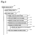
- control device 30 is configured to have an engine control means 20C controlling the operation of the engine 10, a diesel particulate filter (DPF) control means 30C for the exhaust gas purification system 1, etc. as shown in Fig. 2 .
- DPF control means 30C is configured to have a normal operation control means 31C, a collection amount detection means 32C, a running distance detection means 33C, a regeneration time determination means 34C, a regeneration control means 35C, a arbitrary regeneration warning means 36C, etc.
- the normal operation control means 31C is, in particular, a means for performing a normal operation that is performed without any relation to the regeneration of the continuous regeneration type DPF device 12.
- This means 31C performs a normal injection control in which a predetermined amount of the fuel is injected from the fuel injection device 17 into cylinders by the current supply time signal calculated in the control device 30 based on the signal of the accelerator position sensor 24 and the signal of the speed sensor 25. That is, this means 31C is a means that does not especially perform a control for the regeneration control.
- the collection amount detection means 32C is a means to detect the collection amount of PM collected in the filter with catalyst 12b in the continuous regeneration type DPF device 12.
- the collection amount of PM is detected using a pressure difference between the upstream side and the downstream side of the continuous regeneration type DPF device 12, that is, a measured value ⁇ Pm by the differential pressure sensor 21.
- the running distance detection means 33C is a means to detect a distance ⁇ Mc that the vehicle has run after the DPF regeneration. In the case where the forced regeneration has been performed, this running distance ⁇ Mc is reset at an appropriate time in a period from start of regeneration to end of the regeneration.
- the regeneration time determination means 34C is a means to determine the time to start the regeneration of the DPF by comparing each of the differential pressure detection value ⁇ Pm and the running distance ⁇ Mc detected by the running distance detection means 33C with a predetermined determination value.
- the regeneration control means 35C is configured to have an exhaust gas temperature raising means 351C although the control differs a little depending on the types of the continuous regeneration type DPF device 12.
- This exhaust gas temperature raising means 351C is a means to raise the exhaust gas temperature Tg1 to the active temperature of the oxidation catalyst 12a in the case where the exhaust gas temperature Tg1 detected with the oxidation catalyst inlet exhaust gas temperature sensor 22 is lower than a predetermined first determination temperature Tc.
- a first exhaust gas temperature raising control is performed in the case where the temperature Tg1 of the exhaust gas flowing into the continuous regeneration type DPF device 12 is lower than the predetermined first determination temperature Tc (the predetermined determination value).
- a multiple injection (multiple-stage delayed injection), an air-intake throttling, and an exhaust gas throttling are performed without performing the post injection.
- a second exhaust gas temperature raising control is performed in the case where the exhaust gas temperature Tg1 is higher than the predetermined first determination temperature Tc.
- the air-intake throttling and the exhaust gas throttling are performed together with performing the post injection (the after-injection) in addition to the multiple injection in in-cylinder (in-tube) injection of the engine 10.
- an air-intake throttle amount ⁇ in the first exhaust gas temperature raising control in which the post injection is not performed is made to be larger than an air-intake throttle amount ⁇ in the second exhaust gas temperature raising control in which the post injection is performed. That is, it is made to be a deeper air-intake throttling in the first exhaust gas temperature raising control.
- an EGR control together in this exhaust gas temperature raising control is a case of using an EGR control together in this exhaust gas temperature raising control.
- a control to change the air-intake throttle amount depending on whether there is a post injection amount or not that is, a control to change the ratio of an opening of the air-intake throttle valve 16 to a full opening of the air-intake throttle valve 16, is performed.
- the temperature of the oxidation catalyst 12a is raised by quickly raising the exhaust gas temperature while preventing white smoke from being produced. Together with this, the amount of intake oxygen is increased through decreasing the air-intake throttling.
- fuel oxidation reactivity of the oxidation catalyst is improved, and the regeneration control can be performed efficiently. That is, the temperature is raised quickly in the exhaust gas temperature raising control because when the exhaust gas temperature is low in which the post injection cannot be performed, the intake air is throttled further than when the post injection is possible in the first exhaust gas temperature raising control.
- the arbitrary regeneration warning means 36C is configured with a flasher (a DPF lamp) 26, a warning lamp 27, etc.
- This means 36C is a means to perform a warning to urge a driver to operate the regeneration control means 35C manually with flashing of the flasher 26 and to urge the driver to bring the vehicle to a service center with lighting of the warning lamp 27.
- the driver who received this warning can start the regeneration control by the regeneration control means 35C by operating the manual regeneration button (manual regeneration switch) 28.
- the DPF control means 30C having these various means is configured as a means to continue normal operation by the normal operation control means 31C, to perform a warning to urge a driver to manually operate the regeneration control means 35C, and to make the regeneration control means 35C operate automatically based on the differential pressure ⁇ Pm between the upstream side and the downstream side of the DPF detected by the collection amount detection means 32C and the running distance ⁇ Mc after the DPF regeneration detected by the running distance detection means 33C.
- the necessity of the arbitrary regeneration or the necessity of the running automatic regeneration is determined depending on whether the differential pressure ⁇ Pm between the upstream side and the downstream side of the DPF detected by the collection amount detection means 32C and the running distance ⁇ Mc detected by the running distance detection means 33C are in a predetermined range or not.
- a normal operation is performed by the normal operation control means 31C. Then, the operation of the vehicle is performed while repeating the normal operation and the DPF control.
- This DPF control is explained by referring to the map for the DPF control shown in Fig. 4 . Moreover, this DPF control can be carried out with the DPF control flow as exemplified in Fig. 5 .
- the flasher (DPF lamp) 26 is slowly flashed when the detected differential pressure ⁇ Pm between the upstream side and the downstream side of the DPF exceeds the first threshold ⁇ P1 (a manual flash 1) in order that the arbitrary regeneration (manual regeneration) performing the forced regeneration by stopping the vehicle and pushing the manual regeneration bottom 28 is urged without performing the automatic forced regeneration because the running is yet insufficient and the evaporation of the fuel mixed into the engine oil is not performed sufficiently.
- the flasher 26 is flashed quickly when the detected differential pressure ⁇ Pm between the upstream side and the downstream side of the DPF exceeds the second threshold ⁇ P2 (a manual flash 2) larger than the first threshold ⁇ P1.
- the forced regeneration with manual operation by stopping the vehicle is strongly urged to a driver.
- the regeneration control is performed automatically when the detected differential pressure ⁇ Pm between the upstream side and the downstream side of the DPF exceeds the first threshold ⁇ P1 (a running automatic regeneration 1) because the evaporation of the fuel mixed into the engine oil is performed sufficiently and the automatic forced regeneration during running (running automatic regeneration) is possible.
- a burden related to the forced regeneration with manual that is, a burden related to an on/off operation of the manual regeneration bottom 28 on the driver is reduced.
- the regeneration control is performed automatically to prevent thermal runaway caused by uneven accumulation of PM in the filter with catalyst 12b and melting damage of the DPF, without relating to the detected differential pressure ⁇ Pm between the upstream side and the downstream side of the DPF.
- the first exhaust gas temperature raising control is performed for a predetermined time (a time related to the interval of checking the exhaust gas temperature in the step S41) in a step S42, and the program returns to the step S41.
- a multiple injection control, the air-intake throttle control of the air-intake throttle amount ⁇ , and the exhaust gas throttle control are performed without performing the post injection.
- the second exhaust gas temperature raising control is performed for a predetermined time (a time related to an interval of checking the exhaust gas temperature in the step S43) in a step S44, and the program returns to the step S43.
- the air-intake throttle control of the air-intake throttle amount ⁇ and the exhaust gas throttle control are performed together with performing the post injection in addition to the multiple injection.
- the air-intake throttle amount a in the case of the first exhaust gas temperature raising control in which the post injection is not performed is made to be larger than the air-intake throttle amount ⁇ in the case of the second exhaust gas temperature raising control in which the post injection is performed. That is, ⁇ > ⁇ .
- an EGR control together in these exhaust gas temperature raising controls is a case of using an EGR control together in these exhaust gas temperature raising controls.
- the air-intake throttle amount is changed depending on whether there is a post injection amount or not. That is, the exhaust gas temperature is raised while avoiding the production of white smoke with a deep air-intake throttling ( ⁇ ) without performing the post injection in the first exhaust gas temperature raising control when the temperature is low in which white smoke is produced (Tg1 ⁇ Tc). Furthermore, in the second exhaust gas temperature raising control when the temperature is high in which white smoke is not produced (Tg1 ⁇ Tc), the post injection is performed with a shallow air-intake throttling ( ⁇ ), and an amount of intake oxygen is increased by decreasing the air-intake throttle amount.
- the post injection fuel is oxidized efficiently with the oxidation catalyst, and the temperature raising performance and the temperature controlling performance of the catalyst are improved.
- the exhaust gas temperature raising controls the exhaust gas temperature is raised quickly, the temperature of the exhaust gas purifier 12 is raised, and the regeneration control is performed efficiently.
- the program proceeds to a step S45 considering that PM has already reached to a temperature at which combustion is started.
- the step S45 whether the lapse time that the exhaust gas temperature Tg2 is the predetermined second determination temperature Tr or more is a predetermined time or more or not is determined. If the lapse time, is not the predetermined time or more in this determination, the program returns to the step S43, and if the lapse time is the predetermined time or more, the program proceeds to a step S46.
- the normal operation control is performed for a predetermined time (a time related to an interval of checking the completion of the regeneration control), and the program proceeds to a step S47.
- the exhaust gas temperature raising control is not especially performed in this normal operation control. That is, when the combustion of PM is started once by increasing the temperature of the filter with catalyst 12b by the exhaust gas temperature raising control, the combustion is continued by the combustion heat of PM. Therefore, the exhaust gas temperature raising control becomes unnecessary, and the program returns to the normal operation control.
- the determination whether the regeneration control is completed or not is performed in the step S47. This determination can be performed whether the lapse time that the temperature Tg2 of the exhaust gas flowing into the filter with catalyst 12b is the predetermined second determination temperature Tr or more exceeds the regeneration time that is set in advance or not, or whether the differential pressure between the upstream side and the downstream side of the filter is a predetermined value or less or not.
- the program returns to the step S41 and exhaust is repeated until the regeneration control completes. Then, the exhaust gas temperature Tg1 and the exhaust gas temperature Tg2 are observed in the step S41 and the step S43. When these temperatures are decreased, the exhaust gas temperature raising control is restarted.
- the combustion state of PM may be configured to restart the temperature raising control if needed while monitoring the oxygen concentration and the exhaust gas temperature on the downstream side of the continuous regeneration type DPF device 12.
- an operation to finish the regeneration control of a step S48 is performed and the program returns.
- finishing of the multiple injection and the post injection controls, finishing of the DPF regeneration control of the air-intake throttling, and finishing of the DPF regeneration control of the exhaust gas throttling are performed.
- a regeneration control flag may be reset in order to memorize that the regeneration control is finished if needed.
- the warning lamp 27 is lighted to urge a driver to bring the vehicle to a service center together with making a state in which the arbitrary regeneration and the running automatic regeneration are inhibited in order to avoid the thermal runaway that is a rapid combustion of PM.
- the first exhaust gas temperature raising control is performed with a deep air-intake throttling ( ⁇ ) without performing the post injection so that white smoke is not produced in the post injection when the exhaust gas temperature is low.
- the second exhaust gas temperature raising control in which the post injection is performed with a shallow air-intake throttling ( ⁇ ) is performed because white smoke is not produced in the post injection when the exhaust gas temperature is high.
- a device provided with the oxidation catalyst on the upstream side of the filter together with making the filter carry the catalyst is explained as an example of the continuous regeneration type DPF device in the exhaust gas purification system in the above-described explanation.
- the present invention is not limited to this and is applicable to the continuous regeneration type DPF device of other types such as a continuous regeneration type DPF device in which the catalyst is carried on the filter and a continuous regeneration type DPF device provided with the oxidation catalyst on the upstream side of the filter.
- the present invention is applicable in the regeneration control at the recovery of NOx purification ability of a NOx purification catalyst such as a NOx occlusion reduction type catalyst and a NOx direct reduction type catalyst. Furthermore, the present invention is applicable in a sulfur purge, etc. to recover from a sulfur poisoning in the case where the exhaust gas purifier is carrying an oxidation catalyst, a NOx occlusion reduction type catalyst, a NOx direct reduction type catalyst, a SCR catalyst (selective reduction type catalyst), etc.
- the exhaust gas temperature can be raised efficiently while preventing the production of white smoke at the exhaust gas temperature raising control to recover the purification ability of the exhaust gas purifier to purify components in the exhaust gas of an internal combustion engine such as a diesel engine. Therefore, they can be utilized extremely efficiently as a method of controlling an exhaust gas purification system and an exhaust gas purification system in an internal combustion engine mounted on an automobile.
Landscapes
- Engineering & Computer Science (AREA)
- Chemical & Material Sciences (AREA)
- Combustion & Propulsion (AREA)
- Mechanical Engineering (AREA)
- General Engineering & Computer Science (AREA)
- Chemical Kinetics & Catalysis (AREA)
- Materials Engineering (AREA)
- Health & Medical Sciences (AREA)
- Biomedical Technology (AREA)
- Environmental & Geological Engineering (AREA)
- Analytical Chemistry (AREA)
- General Chemical & Material Sciences (AREA)
- Oil, Petroleum & Natural Gas (AREA)
- Toxicology (AREA)
- Processes For Solid Components From Exhaust (AREA)
- Control Of Throttle Valves Provided In The Intake System Or In The Exhaust System (AREA)
- Exhaust Gas After Treatment (AREA)
- Electrical Control Of Air Or Fuel Supplied To Internal-Combustion Engine (AREA)
- Exhaust Gas Treatment By Means Of Catalyst (AREA)
Applications Claiming Priority (2)
| Application Number | Priority Date | Filing Date | Title |
|---|---|---|---|
| JP2005206825A JP3988776B2 (ja) | 2005-07-15 | 2005-07-15 | 排気ガス浄化システムの制御方法及び排気ガス浄化システム |
| PCT/JP2006/312352 WO2007010701A1 (ja) | 2005-07-15 | 2006-06-20 | 排気ガス浄化システムの制御方法及び排気ガス浄化システム |
Publications (3)
| Publication Number | Publication Date |
|---|---|
| EP1905992A1 true EP1905992A1 (de) | 2008-04-02 |
| EP1905992A4 EP1905992A4 (de) | 2015-04-15 |
| EP1905992B1 EP1905992B1 (de) | 2018-08-08 |
Family
ID=37668586
Family Applications (1)
| Application Number | Title | Priority Date | Filing Date |
|---|---|---|---|
| EP06767011.7A Active EP1905992B1 (de) | 2005-07-15 | 2006-06-20 | Verfahren zur steuerung eines abgasreinigungsystems und abgasreinigungssystem |
Country Status (5)
| Country | Link |
|---|---|
| US (1) | US8171725B2 (de) |
| EP (1) | EP1905992B1 (de) |
| JP (1) | JP3988776B2 (de) |
| CN (1) | CN101223348B (de) |
| WO (1) | WO2007010701A1 (de) |
Cited By (4)
| Publication number | Priority date | Publication date | Assignee | Title |
|---|---|---|---|---|
| WO2012126892A1 (en) | 2011-03-23 | 2012-09-27 | Umicore Ag & Co. Kg | Method for operating diesel engines to avoid the formation of white smoke during diesel particulate filter regeneration |
| WO2015023350A1 (en) * | 2013-08-14 | 2015-02-19 | Carrier Corporation | Diesel engine powered transportation refrigeration system |
| EP2857647A4 (de) * | 2012-06-01 | 2016-01-13 | Toyota Motor Co Ltd | Abgasreinigungsvorrichtung für einen verbrennungsmotor |
| EP3051086A4 (de) * | 2013-09-27 | 2017-04-26 | Mitsubishi Heavy Industries, Ltd. | Steuerungsvorrichtung für dpf-regeneration |
Families Citing this family (24)
| Publication number | Priority date | Publication date | Assignee | Title |
|---|---|---|---|---|
| JP2009036177A (ja) * | 2007-08-03 | 2009-02-19 | Denso Corp | 内燃機関の排気浄化装置 |
| US8126632B2 (en) * | 2007-10-26 | 2012-02-28 | Ford Global Technologies, Llc | Engine idle speed and turbocharger speed control |
| US8474247B2 (en) * | 2009-03-18 | 2013-07-02 | GM Global Technology Operations LLC | Particulate filter regeneration post-injection fuel rate control |
| JP5210995B2 (ja) * | 2009-08-20 | 2013-06-12 | 株式会社クボタ | ディーゼルエンジンの排気処理装置 |
| JP5155979B2 (ja) | 2009-10-21 | 2013-03-06 | ヤンマー株式会社 | ディーゼルエンジン |
| JP5206644B2 (ja) * | 2009-10-22 | 2013-06-12 | 株式会社豊田自動織機 | ディーゼルエンジンの排気ガス浄化装置 |
| KR20110062127A (ko) * | 2009-12-02 | 2011-06-10 | 현대자동차주식회사 | 매연필터의 재생 제어방법 |
| JP5325090B2 (ja) * | 2009-12-25 | 2013-10-23 | 三菱重工業株式会社 | 内燃機関の排気浄化装置 |
| JP5404460B2 (ja) | 2010-02-09 | 2014-01-29 | 三菱重工業株式会社 | エンジンの排気浄化装置及び方法、並びにエンジンの排気浄化装置に係るフィルタの再生システム |
| US8347612B2 (en) * | 2010-03-19 | 2013-01-08 | GM Global Technology Operations LLC | Method and apparatus for regenerating a particulate filter system |
| JP2011220232A (ja) * | 2010-04-09 | 2011-11-04 | Ud Trucks Corp | エンジンの排気浄化装置 |
| US10371027B2 (en) * | 2010-04-30 | 2019-08-06 | Yanmar Co., Ltd. | Exhaust gas purification system of working machine |
| US8429899B2 (en) * | 2010-08-09 | 2013-04-30 | GM Global Technology Operations LLC | Target particulate matter filter regeneration and temperature control system |
| KR101326812B1 (ko) * | 2011-05-17 | 2013-11-07 | 현대자동차 주식회사 | 배기가스 후처리 방법 |
| JP5864901B2 (ja) * | 2011-05-19 | 2016-02-17 | 日野自動車株式会社 | パティキュレートフィルタの手動再生方法 |
| JP5536837B2 (ja) * | 2012-08-03 | 2014-07-02 | ヤンマー株式会社 | ディーゼルエンジン |
| JP5990094B2 (ja) * | 2012-12-06 | 2016-09-07 | 株式会社クボタ | ディーゼルエンジンの排気処理装置 |
| WO2014087536A1 (ja) * | 2012-12-07 | 2014-06-12 | トヨタ自動車株式会社 | 排気浄化装置の異常検出装置 |
| JP5655114B2 (ja) * | 2013-06-24 | 2015-01-14 | ヤンマー株式会社 | 排気ガス浄化システム |
| JP6228525B2 (ja) * | 2014-09-29 | 2017-11-08 | 株式会社クボタ | ディーゼルエンジン |
| JP6546541B2 (ja) * | 2016-01-29 | 2019-07-17 | 三菱重工エンジン&ターボチャージャ株式会社 | 排ガス処理装置の再生制御装置 |
| US9689331B1 (en) * | 2016-03-24 | 2017-06-27 | GM Global Technology Operations LLC | Method and apparatus to control fuel injection in an internal combustion engine |
| CN107762653B (zh) * | 2017-10-10 | 2020-03-17 | 中国第一汽车股份有限公司 | 柴油机氧化催化器温度控制系统 |
| JP2024088294A (ja) * | 2022-12-20 | 2024-07-02 | 株式会社クボタ | ディーゼルエンジン |
Citations (4)
| Publication number | Priority date | Publication date | Assignee | Title |
|---|---|---|---|---|
| US20020073696A1 (en) * | 2000-11-03 | 2002-06-20 | Johannes Kuenstler | Method for regenerating a diesel particulate filter |
| US20020078684A1 (en) * | 2000-12-21 | 2002-06-27 | Carberry Brendan Patrick | Regeneration of diesel engine particulate filter only above low fuel levels |
| EP1431549A2 (de) * | 2002-12-20 | 2004-06-23 | Isuzu Motors Limited | Kraftstoffeinspritzsteuerungsvorrichtung |
| US20050039444A1 (en) * | 2003-07-31 | 2005-02-24 | Nissan Motor Co., Ltd. | Combustion control apparatus for internal combustion engine |
Family Cites Families (9)
| Publication number | Priority date | Publication date | Assignee | Title |
|---|---|---|---|---|
| EP0158887B1 (de) * | 1984-03-31 | 1990-11-22 | Mitsubishi Jidosha Kogyo Kabushiki Kaisha | Regenerationssystem für eine Diesel-Partikel-Oxydierungseinrichtung |
| JP2001115822A (ja) * | 1999-10-19 | 2001-04-24 | Hino Motors Ltd | ディーゼルエンジンのパティキュレートフィルタ再生装置 |
| JP4161546B2 (ja) * | 2001-06-26 | 2008-10-08 | いすゞ自動車株式会社 | 連続再生型ディーゼルパティキュレートフィルタ装置の再生制御方法 |
| JP2003083139A (ja) | 2001-09-10 | 2003-03-19 | Hino Motors Ltd | 内燃機関の排気昇温装置 |
| JP2003120353A (ja) | 2001-10-12 | 2003-04-23 | Nissan Motor Co Ltd | 内燃機関の過給圧制御装置 |
| JP4052178B2 (ja) * | 2003-05-15 | 2008-02-27 | 日産自動車株式会社 | 内燃機関の排気浄化装置 |
| JP4333289B2 (ja) * | 2003-09-03 | 2009-09-16 | いすゞ自動車株式会社 | 排気ガス浄化システム |
| JP4196872B2 (ja) * | 2004-04-09 | 2008-12-17 | いすゞ自動車株式会社 | エンジンの排気浄化装置 |
| JP4673226B2 (ja) * | 2006-01-27 | 2011-04-20 | いすゞ自動車株式会社 | 排気ガス浄化方法及び排気ガス浄化システム |
-
2005
- 2005-07-15 JP JP2005206825A patent/JP3988776B2/ja not_active Expired - Fee Related
-
2006
- 2006-06-20 EP EP06767011.7A patent/EP1905992B1/de active Active
- 2006-06-20 WO PCT/JP2006/312352 patent/WO2007010701A1/ja active Application Filing
- 2006-06-20 US US11/922,317 patent/US8171725B2/en not_active Expired - Fee Related
- 2006-06-20 CN CN200680025926XA patent/CN101223348B/zh active Active
Patent Citations (4)
| Publication number | Priority date | Publication date | Assignee | Title |
|---|---|---|---|---|
| US20020073696A1 (en) * | 2000-11-03 | 2002-06-20 | Johannes Kuenstler | Method for regenerating a diesel particulate filter |
| US20020078684A1 (en) * | 2000-12-21 | 2002-06-27 | Carberry Brendan Patrick | Regeneration of diesel engine particulate filter only above low fuel levels |
| EP1431549A2 (de) * | 2002-12-20 | 2004-06-23 | Isuzu Motors Limited | Kraftstoffeinspritzsteuerungsvorrichtung |
| US20050039444A1 (en) * | 2003-07-31 | 2005-02-24 | Nissan Motor Co., Ltd. | Combustion control apparatus for internal combustion engine |
Non-Patent Citations (1)
| Title |
|---|
| See also references of WO2007010701A1 * |
Cited By (9)
| Publication number | Priority date | Publication date | Assignee | Title |
|---|---|---|---|---|
| WO2012126892A1 (en) | 2011-03-23 | 2012-09-27 | Umicore Ag & Co. Kg | Method for operating diesel engines to avoid the formation of white smoke during diesel particulate filter regeneration |
| DE102011014718A1 (de) | 2011-03-23 | 2012-10-11 | Umicore Ag & Co. Kg | Verfahren zum Betrieb von Dieselmotoren zur Vermeidung von Weißrauchbildung während der DPF-Regeneration |
| DE102011014718B4 (de) * | 2011-03-23 | 2012-11-22 | Umicore Ag & Co. Kg | Verfahren zum Betrieb von Dieselmotoren zur Vermeidung von Weißrauchbildung während der DPF-Regeneration |
| EP2857647A4 (de) * | 2012-06-01 | 2016-01-13 | Toyota Motor Co Ltd | Abgasreinigungsvorrichtung für einen verbrennungsmotor |
| US9745877B2 (en) | 2012-06-01 | 2017-08-29 | Toyota Jidosha Kabushiki Kaisha | Exhaust gas purification apparatus for an internal combustion engine |
| WO2015023350A1 (en) * | 2013-08-14 | 2015-02-19 | Carrier Corporation | Diesel engine powered transportation refrigeration system |
| US9884539B2 (en) | 2013-08-14 | 2018-02-06 | Carrier Corporation | Diesel engine powered transportation refrigeration system |
| EP3051086A4 (de) * | 2013-09-27 | 2017-04-26 | Mitsubishi Heavy Industries, Ltd. | Steuerungsvorrichtung für dpf-regeneration |
| US9719440B2 (en) | 2013-09-27 | 2017-08-01 | Mitsubishi Heavy Industries, Ltd. | DPF regeneration control device |
Also Published As
| Publication number | Publication date |
|---|---|
| US8171725B2 (en) | 2012-05-08 |
| WO2007010701A1 (ja) | 2007-01-25 |
| CN101223348A (zh) | 2008-07-16 |
| CN101223348B (zh) | 2011-03-16 |
| EP1905992A4 (de) | 2015-04-15 |
| JP3988776B2 (ja) | 2007-10-10 |
| US20090235644A1 (en) | 2009-09-24 |
| EP1905992B1 (de) | 2018-08-08 |
| JP2007023883A (ja) | 2007-02-01 |
Similar Documents
| Publication | Publication Date | Title |
|---|---|---|
| EP1905992B1 (de) | Verfahren zur steuerung eines abgasreinigungsystems und abgasreinigungssystem | |
| EP1905991B1 (de) | Steuerverfahren für abgasreinigungssystem und abgasreinigungssystem | |
| JP4161932B2 (ja) | 排気ガス浄化システムの制御方法及び排気ガス浄化システム | |
| JP4100451B1 (ja) | 排気ガス浄化方法及び排気ガス浄化システム | |
| US7721534B2 (en) | Control method for an exhaust gas purification system and an exhaust gas purification system | |
| JP4175281B2 (ja) | 排気ガス浄化システムの制御方法及び排気ガス浄化システム | |
| US7992383B2 (en) | Method for controlling exhaust gas purification system and exhaust gas purification system | |
| JP4161930B2 (ja) | 排気ガス浄化システムの制御方法及び排気ガス浄化システム | |
| JP3979437B1 (ja) | 排気ガス浄化システムの制御方法及び排気ガス浄化システム | |
| JP4161931B2 (ja) | 排気ガス浄化システムの制御方法及び排気ガス浄化システム | |
| EP1400664B1 (de) | Verfahren und Vorrichtung zur Reinigung von Abgas | |
| US20090235647A1 (en) | Method for Controlling Exhaust Gas Purification System and Exhaust Gas Purification System | |
| WO2007086253A1 (ja) | 排気ガス浄化方法及び排気ガス浄化システム | |
| WO2007145044A1 (ja) | 排気ガス浄化システムの制御方法及び排気ガス浄化システム | |
| JP4466158B2 (ja) | 排気ガス浄化システムの制御方法及び排気ガス浄化システム | |
| JP4311253B2 (ja) | 排気ガス浄化システムの制御方法及び排気ガス浄化システム | |
| JP2007023876A (ja) | 排気ガス浄化システムの制御方法及び排気ガス浄化システム | |
| JP4517682B2 (ja) | 排気ガス浄化システム | |
| JP4352946B2 (ja) | 排気ガス浄化システム |
Legal Events
| Date | Code | Title | Description |
|---|---|---|---|
| PUAI | Public reference made under article 153(3) epc to a published international application that has entered the european phase |
Free format text: ORIGINAL CODE: 0009012 |
|
| 17P | Request for examination filed |
Effective date: 20080123 |
|
| AK | Designated contracting states |
Kind code of ref document: A1 Designated state(s): DE FR GB IT |
|
| DAX | Request for extension of the european patent (deleted) | ||
| RBV | Designated contracting states (corrected) |
Designated state(s): DE FR GB IT |
|
| DAX | Request for extension of the european patent (deleted) | ||
| RA4 | Supplementary search report drawn up and despatched (corrected) |
Effective date: 20150318 |
|
| RIC1 | Information provided on ipc code assigned before grant |
Ipc: F02D 41/04 20060101AFI20150312BHEP Ipc: F02D 41/02 20060101ALN20150312BHEP Ipc: F02D 9/02 20060101ALI20150312BHEP Ipc: F02D 41/40 20060101ALI20150312BHEP Ipc: F01N 3/24 20060101ALI20150312BHEP Ipc: F02D 41/14 20060101ALI20150312BHEP Ipc: B01D 53/94 20060101ALI20150312BHEP Ipc: F01N 3/28 20060101ALI20150312BHEP Ipc: F01N 3/02 20060101ALI20150312BHEP Ipc: F02D 41/38 20060101ALI20150312BHEP Ipc: F01N 3/023 20060101ALI20150312BHEP |
|
| GRAP | Despatch of communication of intention to grant a patent |
Free format text: ORIGINAL CODE: EPIDOSNIGR1 |
|
| INTG | Intention to grant announced |
Effective date: 20180208 |
|
| GRAS | Grant fee paid |
Free format text: ORIGINAL CODE: EPIDOSNIGR3 |
|
| GRAA | (expected) grant |
Free format text: ORIGINAL CODE: 0009210 |
|
| RAP1 | Party data changed (applicant data changed or rights of an application transferred) |
Owner name: ISUZU MOTORS LIMITED |
|
| AK | Designated contracting states |
Kind code of ref document: B1 Designated state(s): DE FR GB IT |
|
| REG | Reference to a national code |
Ref country code: GB Ref legal event code: FG4D |
|
| RIN1 | Information on inventor provided before grant (corrected) |
Inventor name: MASHIKO, TATSUO Inventor name: IKEDA, SHIGERU Inventor name: WU, WEI Inventor name: OCHI, NAOFUMI |
|
| REG | Reference to a national code |
Ref country code: DE Ref legal event code: R096 Ref document number: 602006056041 Country of ref document: DE |
|
| PG25 | Lapsed in a contracting state [announced via postgrant information from national office to epo] |
Ref country code: IT Free format text: LAPSE BECAUSE OF FAILURE TO SUBMIT A TRANSLATION OF THE DESCRIPTION OR TO PAY THE FEE WITHIN THE PRESCRIBED TIME-LIMIT Effective date: 20180808 |
|
| REG | Reference to a national code |
Ref country code: DE Ref legal event code: R097 Ref document number: 602006056041 Country of ref document: DE |
|
| PLBE | No opposition filed within time limit |
Free format text: ORIGINAL CODE: 0009261 |
|
| STAA | Information on the status of an ep patent application or granted ep patent |
Free format text: STATUS: NO OPPOSITION FILED WITHIN TIME LIMIT |
|
| 26N | No opposition filed |
Effective date: 20190509 |
|
| PGFP | Annual fee paid to national office [announced via postgrant information from national office to epo] |
Ref country code: GB Payment date: 20220428 Year of fee payment: 17 Ref country code: FR Payment date: 20220510 Year of fee payment: 17 |
|
| PGFP | Annual fee paid to national office [announced via postgrant information from national office to epo] |
Ref country code: DE Payment date: 20230502 Year of fee payment: 18 |
|
| GBPC | Gb: european patent ceased through non-payment of renewal fee |
Effective date: 20230620 |
|
| PG25 | Lapsed in a contracting state [announced via postgrant information from national office to epo] |
Ref country code: GB Free format text: LAPSE BECAUSE OF NON-PAYMENT OF DUE FEES Effective date: 20230620 |
|
| PG25 | Lapsed in a contracting state [announced via postgrant information from national office to epo] |
Ref country code: FR Free format text: LAPSE BECAUSE OF NON-PAYMENT OF DUE FEES Effective date: 20230630 |