EP1894883A2 - Crane vehicle - Google Patents
Crane vehicle Download PDFInfo
- Publication number
- EP1894883A2 EP1894883A2 EP07116452A EP07116452A EP1894883A2 EP 1894883 A2 EP1894883 A2 EP 1894883A2 EP 07116452 A EP07116452 A EP 07116452A EP 07116452 A EP07116452 A EP 07116452A EP 1894883 A2 EP1894883 A2 EP 1894883A2
- Authority
- EP
- European Patent Office
- Prior art keywords
- tower
- crane according
- vehicle crane
- jib
- vehicle
- Prior art date
- Legal status (The legal status is an assumption and is not a legal conclusion. Google has not performed a legal analysis and makes no representation as to the accuracy of the status listed.)
- Granted
Links
Images


Classifications
-
- B—PERFORMING OPERATIONS; TRANSPORTING
- B66—HOISTING; LIFTING; HAULING
- B66C—CRANES; LOAD-ENGAGING ELEMENTS OR DEVICES FOR CRANES, CAPSTANS, WINCHES, OR TACKLES
- B66C23/00—Cranes comprising essentially a beam, boom, or triangular structure acting as a cantilever and mounted for translatory of swinging movements in vertical or horizontal planes or a combination of such movements, e.g. jib-cranes, derricks, tower cranes
- B66C23/18—Cranes comprising essentially a beam, boom, or triangular structure acting as a cantilever and mounted for translatory of swinging movements in vertical or horizontal planes or a combination of such movements, e.g. jib-cranes, derricks, tower cranes specially adapted for use in particular purposes
- B66C23/26—Cranes comprising essentially a beam, boom, or triangular structure acting as a cantilever and mounted for translatory of swinging movements in vertical or horizontal planes or a combination of such movements, e.g. jib-cranes, derricks, tower cranes specially adapted for use in particular purposes for use on building sites; constructed, e.g. with separable parts, to facilitate rapid assembly or dismantling, for operation at successively higher levels, for transport by road or rail
- B66C23/34—Self-erecting cranes, i.e. with hoisting gear adapted for crane erection purposes
-
- B—PERFORMING OPERATIONS; TRANSPORTING
- B66—HOISTING; LIFTING; HAULING
- B66C—CRANES; LOAD-ENGAGING ELEMENTS OR DEVICES FOR CRANES, CAPSTANS, WINCHES, OR TACKLES
- B66C23/00—Cranes comprising essentially a beam, boom, or triangular structure acting as a cantilever and mounted for translatory of swinging movements in vertical or horizontal planes or a combination of such movements, e.g. jib-cranes, derricks, tower cranes
- B66C23/62—Constructional features or details
- B66C23/72—Counterweights or supports for balancing lifting couples
- B66C23/74—Counterweights or supports for balancing lifting couples separate from jib
-
- B—PERFORMING OPERATIONS; TRANSPORTING
- B66—HOISTING; LIFTING; HAULING
- B66C—CRANES; LOAD-ENGAGING ELEMENTS OR DEVICES FOR CRANES, CAPSTANS, WINCHES, OR TACKLES
- B66C23/00—Cranes comprising essentially a beam, boom, or triangular structure acting as a cantilever and mounted for translatory of swinging movements in vertical or horizontal planes or a combination of such movements, e.g. jib-cranes, derricks, tower cranes
- B66C23/18—Cranes comprising essentially a beam, boom, or triangular structure acting as a cantilever and mounted for translatory of swinging movements in vertical or horizontal planes or a combination of such movements, e.g. jib-cranes, derricks, tower cranes specially adapted for use in particular purposes
- B66C23/185—Cranes comprising essentially a beam, boom, or triangular structure acting as a cantilever and mounted for translatory of swinging movements in vertical or horizontal planes or a combination of such movements, e.g. jib-cranes, derricks, tower cranes specially adapted for use in particular purposes for use erecting wind turbines
-
- B—PERFORMING OPERATIONS; TRANSPORTING
- B66—HOISTING; LIFTING; HAULING
- B66C—CRANES; LOAD-ENGAGING ELEMENTS OR DEVICES FOR CRANES, CAPSTANS, WINCHES, OR TACKLES
- B66C23/00—Cranes comprising essentially a beam, boom, or triangular structure acting as a cantilever and mounted for translatory of swinging movements in vertical or horizontal planes or a combination of such movements, e.g. jib-cranes, derricks, tower cranes
- B66C23/18—Cranes comprising essentially a beam, boom, or triangular structure acting as a cantilever and mounted for translatory of swinging movements in vertical or horizontal planes or a combination of such movements, e.g. jib-cranes, derricks, tower cranes specially adapted for use in particular purposes
- B66C23/26—Cranes comprising essentially a beam, boom, or triangular structure acting as a cantilever and mounted for translatory of swinging movements in vertical or horizontal planes or a combination of such movements, e.g. jib-cranes, derricks, tower cranes specially adapted for use in particular purposes for use on building sites; constructed, e.g. with separable parts, to facilitate rapid assembly or dismantling, for operation at successively higher levels, for transport by road or rail
- B66C23/34—Self-erecting cranes, i.e. with hoisting gear adapted for crane erection purposes
- B66C23/342—Self-erecting cranes, i.e. with hoisting gear adapted for crane erection purposes with telescopic elements
-
- B—PERFORMING OPERATIONS; TRANSPORTING
- B66—HOISTING; LIFTING; HAULING
- B66C—CRANES; LOAD-ENGAGING ELEMENTS OR DEVICES FOR CRANES, CAPSTANS, WINCHES, OR TACKLES
- B66C23/00—Cranes comprising essentially a beam, boom, or triangular structure acting as a cantilever and mounted for translatory of swinging movements in vertical or horizontal planes or a combination of such movements, e.g. jib-cranes, derricks, tower cranes
- B66C23/18—Cranes comprising essentially a beam, boom, or triangular structure acting as a cantilever and mounted for translatory of swinging movements in vertical or horizontal planes or a combination of such movements, e.g. jib-cranes, derricks, tower cranes specially adapted for use in particular purposes
- B66C23/26—Cranes comprising essentially a beam, boom, or triangular structure acting as a cantilever and mounted for translatory of swinging movements in vertical or horizontal planes or a combination of such movements, e.g. jib-cranes, derricks, tower cranes specially adapted for use in particular purposes for use on building sites; constructed, e.g. with separable parts, to facilitate rapid assembly or dismantling, for operation at successively higher levels, for transport by road or rail
- B66C23/34—Self-erecting cranes, i.e. with hoisting gear adapted for crane erection purposes
- B66C23/344—Self-erecting cranes, i.e. with hoisting gear adapted for crane erection purposes adapted for transport purposes
-
- B—PERFORMING OPERATIONS; TRANSPORTING
- B66—HOISTING; LIFTING; HAULING
- B66C—CRANES; LOAD-ENGAGING ELEMENTS OR DEVICES FOR CRANES, CAPSTANS, WINCHES, OR TACKLES
- B66C23/00—Cranes comprising essentially a beam, boom, or triangular structure acting as a cantilever and mounted for translatory of swinging movements in vertical or horizontal planes or a combination of such movements, e.g. jib-cranes, derricks, tower cranes
- B66C23/18—Cranes comprising essentially a beam, boom, or triangular structure acting as a cantilever and mounted for translatory of swinging movements in vertical or horizontal planes or a combination of such movements, e.g. jib-cranes, derricks, tower cranes specially adapted for use in particular purposes
- B66C23/26—Cranes comprising essentially a beam, boom, or triangular structure acting as a cantilever and mounted for translatory of swinging movements in vertical or horizontal planes or a combination of such movements, e.g. jib-cranes, derricks, tower cranes specially adapted for use in particular purposes for use on building sites; constructed, e.g. with separable parts, to facilitate rapid assembly or dismantling, for operation at successively higher levels, for transport by road or rail
- B66C23/34—Self-erecting cranes, i.e. with hoisting gear adapted for crane erection purposes
- B66C23/348—Self-erecting cranes, i.e. with hoisting gear adapted for crane erection purposes the erection being operated by jacks
-
- B—PERFORMING OPERATIONS; TRANSPORTING
- B66—HOISTING; LIFTING; HAULING
- B66C—CRANES; LOAD-ENGAGING ELEMENTS OR DEVICES FOR CRANES, CAPSTANS, WINCHES, OR TACKLES
- B66C23/00—Cranes comprising essentially a beam, boom, or triangular structure acting as a cantilever and mounted for translatory of swinging movements in vertical or horizontal planes or a combination of such movements, e.g. jib-cranes, derricks, tower cranes
- B66C23/18—Cranes comprising essentially a beam, boom, or triangular structure acting as a cantilever and mounted for translatory of swinging movements in vertical or horizontal planes or a combination of such movements, e.g. jib-cranes, derricks, tower cranes specially adapted for use in particular purposes
- B66C23/36—Cranes comprising essentially a beam, boom, or triangular structure acting as a cantilever and mounted for translatory of swinging movements in vertical or horizontal planes or a combination of such movements, e.g. jib-cranes, derricks, tower cranes specially adapted for use in particular purposes mounted on road or rail vehicles; Manually-movable jib-cranes for use in workshops; Floating cranes
-
- B—PERFORMING OPERATIONS; TRANSPORTING
- B66—HOISTING; LIFTING; HAULING
- B66C—CRANES; LOAD-ENGAGING ELEMENTS OR DEVICES FOR CRANES, CAPSTANS, WINCHES, OR TACKLES
- B66C23/00—Cranes comprising essentially a beam, boom, or triangular structure acting as a cantilever and mounted for translatory of swinging movements in vertical or horizontal planes or a combination of such movements, e.g. jib-cranes, derricks, tower cranes
- B66C23/62—Constructional features or details
- B66C23/72—Counterweights or supports for balancing lifting couples
- B66C23/78—Supports, e.g. outriggers, for mobile cranes
-
- B—PERFORMING OPERATIONS; TRANSPORTING
- B66—HOISTING; LIFTING; HAULING
- B66C—CRANES; LOAD-ENGAGING ELEMENTS OR DEVICES FOR CRANES, CAPSTANS, WINCHES, OR TACKLES
- B66C23/00—Cranes comprising essentially a beam, boom, or triangular structure acting as a cantilever and mounted for translatory of swinging movements in vertical or horizontal planes or a combination of such movements, e.g. jib-cranes, derricks, tower cranes
- B66C23/62—Constructional features or details
- B66C23/82—Luffing gear
Abstract
Description
Die Erfindung betrifft einen Fahrzeugkran, insbesondere einen Mobil-, Auto- oder Raupenkran.The invention relates to a vehicle crane, in particular a mobile, car or crawler crane.
In der Krantechnologie unterscheidet man gemäß einer gängigen Einteilung zwischen Turmdrehkranen oder Turmkranen einerseits und Fahrzeugkranen andererseits.In crane technology, a distinction is made according to a common classification between tower cranes or tower cranes on the one hand and mobile cranes on the other.
Turmdrehkrane besitzen einen auf einem Unterbau stehenden vertikalen Turm, der meist als Gitterfachwerk ausgebildet ist, und sind - obwohl sie beispielsweise auf Baustellen z.B. mittels eines Gleisfahrwerkes bewegbar sein können - nicht als im normalen Straßenverkehr bewegbare Fahrzeuge konzipiert. Dagegen handelt es sich bei Fahrzeugkranen um selbstfahrende Straßenfahrzeuge, die gerade für den mobilen Einsatz gedacht sind.Tower cranes have a vertical tower standing on a substructure, which is usually designed as a lattice framework, and although they are used, for example, on construction sites, e.g. be movable by means of a track undercarriage - not designed as a vehicle movable in normal traffic. By contrast, mobile cranes are self-propelled road vehicles that are currently being designed for mobile use.
Fahrzeugkrane bestehen aus einem das Fahrgestell umfassenden Unterwagen und einem auf dem Unterwagen drehbaren Oberwagen, der ein Drehwerk und einen Ausleger umfasst. Der Ausleger kann als Teleskopausleger in Kastenbauweise oder als Gittermastausleger ausgebildet sein.Mobile cranes consist of a chassis comprising the chassis and a superstructure rotatable on the undercarriage, comprising a slewing gear and a jib. The boom can be designed as a telescopic boom in box construction or as a lattice boom.
An Krane werden zunehmend höhere Anforderungen gestellt, und zwar sowohl hinsichtlich der Tragkraft oder Hebekapazität als auch hinsichtlich der Höhe, in welche die Lasten gehoben werden müssen.Cranes are increasingly demanding, both in terms of capacity or lifting capacity and in terms of the height in which the loads must be lifted.
Als Einsatzgebiet für Krane gewinnt die Errichtung von Windkraftanlagen immer mehr an Bedeutung, da ein Trend hin zu immer leistungsfähigeren Windkraftanlagen besteht, die damit nicht nur höhere, sondern auch schwerere Komponenten aufweisen.As a field of application for cranes, the construction of wind turbines is becoming increasingly important, as there is a trend towards ever more powerful wind turbines, which not only have higher, but also heavier components.
Problematisch bei der Errichtung von Windkraftanlagen mittels Kranen sind der damit verbundene logistische Aufwand und die nicht zuletzt durch praktisch nicht verhinderbare Flurschäden mit verursachten hohen Kosten, denn für den Aufbau existierender Fahrzeugkrane, die für die Errichtung großer Windkraftanlagen benötigt werden, müssen aufgrund des immensen Krangesamtgewichts derzeit eine Vielzahl einzelner Schwerlasttransporte an die meist entlegenen Aufstellorte der Windkraftanlagen durchgeführt werden.The problem with the construction of wind turbines by means of cranes are the associated logistical effort and not least by virtually unavoidable ground damage caused high costs, because for the construction of existing mobile cranes, which are needed for the construction of large wind turbines, currently due to the immense crane weight a variety of individual heavy load transports to the most remote installation sites of wind turbines are performed.
Aufgabe der Erfindung ist es, einen insbesondere für das Aufstellen von Windkraftanlagen geeigneten Fahrzeugkran zu schaffen, der ein möglichst geringes Gesamtgewicht aufweist und möglichst schnell betriebsbereit gemacht werden kann, um auf diese Weise die Krannutzungskosten möglichst gering zu halten, wobei aber bei der Tragkraft oder Hebekapazität keine Abstriche gemacht werden sollen.The object of the invention is to provide a particular suitable for the installation of wind turbines vehicle crane, which has the lowest possible total weight and can be made ready for use as quickly as possible to keep in this way the Kruutzungskosten as low as possible, but at the carrying capacity or lifting capacity no cuts should be made.
Die Lösung dieser Aufgabe erfolgt durch die Merkmale des Anspruchs 1 und insbesondere dadurch, dass der Fahrzeugkran mit einem als Obendreher ausgebildeten Aufbau versehen ist, der einen vertikalen Turm und auf dem Turm einen Ausleger umfasst.The solution of this object is achieved by the features of
Das erfindungsgemäße Konzept eines oben drehenden Aufbaus mit vertikalem Turm und aufgesetztem Ausleger bedeutet eine Abkehr von dem bislang bei Fahrzeugkranen verfolgten Konstruktionsprinzip, wonach sich das Drehwerk in Höhe des Fahrgestells befindet und der teleskopierbare oder als Gitterfachwerk ausgebildete Mast wegen der notwendigen Standsicherheit in jeder Betriebsstellung zur Vertikalen geneigt und mit einem mitdrehenden Gegengewicht versehen ist. Man spricht in diesem Zusammenhang auch von einer Zwangsausladung. Bei dem erfindungsgemäßen Fahrzeugkran ist eine solche, für Fahrzeugkrane bislang typische Zwangsausladung aufgrund des vertikalen Turmes nicht vorhanden.The inventive concept of a top-rotating structure with vertical tower and attached boom means a departure from the Previously pursued in mobile cranes design principle, according to which the slewing is at the height of the chassis and the telescopic or trained as a lattice truss mast because of the necessary stability in each operating position inclined to the vertical and provided with a co-rotating counterweight. One speaks in this context of a compulsory discharge. In the vehicle crane according to the invention is such, for mobile cranes typical forced discharge due to the vertical tower does not exist.
Es hat sich überraschend herausgestellt, dass das erfindungsgemäße Konzept eines nicht drehenden vertikalen Turmes eine Vielzahl von Vorteilen bietet. Insbesondere lässt sich, da wegen der fehlenden Zwangsausladung keine Gegenmaßnahmen z.B. in Form schwerer Gegengewichte getroffen werden müssen, ein vergleichsweise niedriges - bezogen auf die Tragkraft bzw. Hebekapazität- Krangesamtgewicht realisieren, was sich vorteilhaft auf die Mobilität auswirkt, da nur eine relativ kleine Anzahl von Einzeltransporten erforderlich ist.It has surprisingly been found that the inventive concept of a non-rotating vertical tower offers a variety of advantages. In particular, since there are no countermeasures because of the lack of compulsory discharge, for example. have to be taken in the form of heavy counterweights, a comparatively low - based on the carrying capacity or lifting capacity - realize crane gross weight, which has an advantageous effect on mobility, since only a relatively small number of individual transports is required.
Den erfindungsgemäßen Fahrzeugkran als Obendreher auszulegen, eröffnet des Weiteren vorteilhafte Möglichkeiten für eine gegebenenfalls erforderliche zusätzliche Sicherung bzw. Stabilisierung des Turmes und ermöglicht ferner die Realisierung eines besonders einfachen Konzeptes zum Aufrichten des Turmes. Hierauf wird nachstehend näher eingegangen.Furthermore, designing the vehicle crane according to the invention as a head turner opens up advantageous possibilities for an optionally required additional securing or stabilization of the tower and also makes it possible to realize a particularly simple concept for erecting the tower. This will be discussed in more detail below.
Vorteilhafte Ausführungsformen der Erfindung sind auch in den abhängigen Ansprüchen, der Beschreibung sowie der Zeichnung angegeben.Advantageous embodiments of the invention are also indicated in the dependent claims, the description and the drawings.
Vorzugsweise ist der Ausleger gegenüber dem Turm geneigt. Hierunter ist auch ein horizontaler Verlauf, d.h. ein sich senkrecht zum Turm erstreckender Ausleger zu verstehen.Preferably, the boom is inclined relative to the tower. Among them is also a horizontal course, i. to understand a perpendicular to the tower extending boom.
Des Weiteren ist der Ausleger bevorzugt längenveränderlich und/oder relativ zum Turm winkelverstellbar. Zur Längenveränderung ist der Ausleger vorzugsweise teleskopierbar ausgebildet.Furthermore, the boom is preferably variable in length and / or angle-adjustable relative to the tower. To change the length of the boom is preferably formed telescopic.
Gemäß einem weiteren bevorzugten Ausführungsbeispiel ist der Ausleger ein Bestandteil einer insbesondere als Ganzes transportierbaren Baugruppe, die zusätzlich zu dem Ausleger insbesondere ein Drehwerk, ein Wippwerk, einen Flaschenzug mit Unterflasche und oberem Rollenzug und gegebenenfalls eine Kranführerkabine sowie alle hierfür erforderlichen Antriebseinrichtungen umfasst. Diese den Ausleger umfassende Baugruppe kann insofern als Oberwagen bezeichnet werden, obwohl bei herkömmlichen Fahrzeugkranen unter dem Begriff "Oberwagen" der gesamte unmittelbar auf dem auch als Unterwagen bezeichneten Fahrgestell installierte Aufbau verstanden wird.According to a further preferred embodiment, the boom is a component of a particular transportable as a whole assembly which in addition to the boom in particular a slewing, a luffing, a pulley with lower block and upper pulley and optionally a crane cab and all necessary for this drive means comprises. This assembly comprising the boom can be referred to as a superstructure, although understood in conventional vehicle cranes under the term "superstructure" the entire structure directly on the chassis also referred to as the undercarriage.
Des Weiteren ist erfindungsgemäß bevorzugt vorgesehen, dass der Turm längenveränderlich ist. Vorzugsweise ist der Turm als Teleskopturm ausgebildet.Furthermore, it is preferably provided according to the invention that the tower is variable in length. Preferably, the tower is designed as a telescope tower.
Gemäß einem weiteren bevorzugten Ausführungsbeispiel der Erfindung ist das Eigengewicht des Turmes als Gegengewicht vorgesehen. Anders als bei herkömmlichen Fahrzeugkranen, deren wegen der Zwangsausladung stets schräg stehender Mast ein das Krangesamtgewicht beträchtlich erhöhendes Gegengewicht zugeordnet ist, kann bei dem erfindungsgemäßen Fahrzeugkran auch bei großer Tragkraft bzw. Hebekapazität auf ein solches zusätzliches Gegengewicht verzichtet werden. Es hat sich herausgestellt, dass die Standfestigkeit des gegebenenfalls zusätzlich gesicherten Vertikalturmes ausreichend ist, d.h. die Standsicherheit des erfindungsgemäßen Fahrzeugkranes ist zumindest im Wesentlichen bereits aufgrund des Eigengewichtes des Turmes gegeben; der vertikale Turm wirkt als Zentralballast des Fahrzeugkranes.According to a further preferred embodiment of the invention, the weight of the tower is provided as a counterweight. Unlike in conventional vehicle cranes, whose always due to the forced discharge mast is associated with the crane gross weight considerably increasing counterweight, can in the vehicle crane according to the invention Even with high load capacity or lifting capacity to be dispensed with such an additional counterweight. It has been found that the stability of the possibly additionally secured vertical tower is sufficient, ie the stability of the vehicle crane according to the invention is at least substantially already given due to the weight of the tower; The vertical tower acts as the central ballast of the mobile crane.
In Abhängigkeit von der konkreten Dimensionierung des erfindungsgemäßen Fahrzeugkrans können für den Turm zusätzliche Sicherungs- bzw. Stabilisierungsmaßnahmen vorgesehen werden, auf die nachstehend näher eingegangen wird. Derartige Maßnahmen tragen dann jedoch in einem wesentlich geringeren Umfang zum Krangesamtgewicht bei als die Gegengewichte herkömmlicher Fahrzeugkrane. Es ist aber nicht ausgeschlossen, dass auch bei dem erfindungsgemäßen Fahrzeugkran insbesondere bei sehr großen Lasten bzw. Ausladungen mit einem oder mehreren zusätzlichen Gegengewichten gearbeitet wird. Als derartige Gegengewichte können z.B. wenigstens ein ohnehin vorhandenes, zu diesem Zweck an das Fahrgestell des erfindungsgemäßen Fahrzeugkranes angekoppeltes Hilfsfahrzeug bzw. Hilfskran verwendet werden.Depending on the specific dimensioning of the vehicle crane according to the invention additional security or stabilization measures can be provided for the tower, which will be discussed in more detail below. However, such measures then contribute, to a much lesser extent, to the overall crane weight than the counterweights of conventional mobile cranes. However, it is not excluded that even in the case of the vehicle crane according to the invention, in particular in the case of very large loads or discharges, one or more additional counterweights are used. As such counterweights, e.g. at least one already existing, coupled for this purpose to the chassis of the vehicle crane according to the invention auxiliary vehicle or auxiliary crane can be used.
Des Weiteren wird erfindungsgemäß vorgeschlagen, dass für den Turm eine Abstützung vorgesehen ist. Vorzugsweise umfasst die Abstützung eine Mehrzahl von um den Turm herum verteilten Bodenstützen.Furthermore, the invention proposes that a support is provided for the tower. Preferably, the support comprises a plurality of floor supports distributed around the tower.
Das Eigengewicht des Turmes und die Abstützung können derart aufeinander abgestimmt sein, dass kein zusätzliches Gegengewicht erforderlich ist.The weight of the tower and the support can be coordinated so that no additional counterweight is required.
Gemäß einem weiteren bevorzugten Ausführungsbeispiel der Erfindung ist vorgesehen, dass für den Turm eine Abspannung vorgesehen ist. Durch eine Abspannung kann die Biegesteifigkeit des Turmes erhöht werden, da eine in einer bestimmten Höhe am Turm angreifende Abspannung die in die Berechnung der kritischen Biegebelastung mit 1/L2 eingehende effektive Länge L des Turmes verringert.According to a further preferred embodiment of the invention it is provided that a bracing is provided for the tower. By bracing the bending stiffness of the tower can be increased, since a at a certain height on the tower attacking bracing reduces the incoming in the calculation of the critical bending load with 1 / L 2 effective length L of the tower.
Vorzugsweise umfasst die Abspannung eine Mehrzahl von um den Turm herum verteilten Abspannorganen, die insbesondere jeweils in Form eines Abspannseiles vorgesehen sind.The bracing preferably comprises a plurality of bracing elements distributed around the tower, which in particular are each provided in the form of a guy rope.
Die Möglichkeit, die Belastbarkeit des Turmes durch eine Abspannung beträchtlich zu erhöhen, ist einer der Vorteile des erfindungsgemäßen Konzepts, einen als Obendreher ausgebildeten Aufbau mit vertikalem Turm vorzusehen, da bei einem unten drehenden Aufbau ein Abspannen nicht möglich ist.The possibility of considerably increasing the load capacity of the tower by means of bracing is one of the advantages of the inventive concept of providing a top-tower structure with a vertical tower, since it is not possible to brace it in a bottom-rotating structure.
Wenn es sich bei dem Turm um einen Teleskopturm handelt, dann ist vorzugsweise vorgesehen, dass die Abspannung an einem oder mehreren auch als Kästen oder Schüsse bezeichneten Turmsegmenten angreift. Besonders vorteilhaft ist eine an mehreren Turmsegmenten und damit an längs des Turmes beabstandeten Stellen angreifende Abspannung, da hierdurch eine besonders starke Reduzierung der effektiven Turmlänge und damit Erhöhung der maximalen Biegebeanspruchung des Turmes erzielt werden kann. Insbesondere kann hierbei die Abspannung im Bereich der auch bei zusammen geschobenem Turm zugänglichen oberen Enden der jeweiligen Turmsegmente angreifen. Im Rahmen der Erfindung kann eine an mehreren längs des Turmes beabstandeten Positionen angreifende Abspannung aber auch in Verbindung mit einem nicht teleskopierbaren Turm vorgesehen werden.If the tower is a telescope tower, then it is preferably provided that the bracing acts on one or more tower segments, also referred to as boxes or shots. Particularly advantageous is a at several tower segments and thus at along the tower spaced locations attacking bracing, as a result, a particularly strong reduction of the effective length of the tower and thus increasing the maximum bending stress of the tower can be achieved. In particular, this can attack the bracing in the region of the upper ends of the respective tower segments which are accessible even when the tower is pushed together. Within the scope of the invention a bracing acting on a plurality of positions spaced along the tower but also provided in connection with a non-telescopic tower.
Besonders vorteilhaft ist es, wenn gemäß einer weiteren Ausführungsform der Erfindung die Abspannung zumindest zum Teil mit einer Turmabstützung verbunden ist. Auf zusätzliche Bodenverankerungen oder andere Verankerungen für die Abspannung kann hierdurch verzichtet werden, wobei erfindungsgemäß aber auch nicht ausgeschlossen ist, dass alternativ oder zusätzlich zu einer Verankerung an der Turmabstützung andere Verankerungen zum Einsatz kommen.It is particularly advantageous if, according to a further embodiment of the invention, the bracing is connected at least in part to a tower support. Additional ground anchors or other anchoring means for the bracing can be dispensed with, but according to the invention it is also not excluded that, alternatively or in addition to an anchoring to the tower support, other anchors are used.
Ferner wird erfindungsgemäß vorgeschlagen, dass der Ausleger mit einem Gegenausleger versehen ist. Vorzugsweise ist der Gegenausleger zum Verändern des durch ihn auf den Turm einwirkenden Biegemomentes einstellbar. Hierzu kann der Gegenausleger insbesondere längenveränderlich, beispielsweise teleskopierbar, und/oder relativ zum Turm winkelverstellbar ausgebildet sein.Furthermore, the invention proposes that the boom is provided with a counter-jib. Preferably, the counter-jib is adjustable for varying the bending moment acting on it by the tower. For this purpose, the counter-jib in particular variable in length, for example, telescopic, and / or be designed to be angularly adjustable relative to the tower.
Mit einem Gegenausleger können lastbedingte - also über den die zu hebende Last tragenden Ausleger auf den Turm einwirkende - Biegemomente zumindest teilweise kompensiert werden. Insbesondere lässt sich erreichen, dass der Turm zumindest weitgehend biegemomentfrei ist.With a counter-jib, load-induced bending moments - that is to say over the jib carrying the load to be lifted - acting on the tower can be at least partially compensated. In particular, it can be achieved that the tower is at least largely free of bending moment.
In einem besonders bevorzugten Ausführungsbeispiel ist eine Steuer- und/oder Regeleinrichtung vorgesehen, mittels welcher der Gegenausleger in Abhängigkeit vom Momentanlastmoment einstellbar ist. Hierdurch kann während des Kranbetriebs der Turm auch bei Veränderungen der Lastsituation am Ausleger stets zumindest im Wesentlichen biegemomentfrei gehalten werden, indem auf Veränderungen der Lastsituation am Ausleger automatisch durch eine Änderung der Gegenauslegereinstellung reagiert wird, beispielsweise durch Längenveränderung oder Winkelverstellung relativ zum Turm.In a particularly preferred embodiment, a control and / or regulating device is provided, by means of which the counter-jib is adjustable in dependence on the instantaneous load torque. As a result, during the crane operation of the tower even with changes in Load situation on the boom are always kept at least substantially free of bending moment by automatically responding to changes in the load situation on the boom by changing the counter-jib adjustment, for example, by length change or angular displacement relative to the tower.
Gemäß einem weiteren Ausführungsbeispiel der Erfindung ist für das untere Ende des Turmes eine insbesondere topf- oder napfförmige Turmaufnahme vorgesehen, die zwei beabstandete Fahrgestellteile miteinander verbindet. Hierdurch bildet die Turmaufnahme einen Bestandteil des Fahrgestells. Bevorzugt ist bei in Transportlage befindlichem Turm dessen unteres Ende von der Turmaufnahme getrennt. Diese Trennung von Turm und Turmaufnahme ermöglicht einen Transport mit auf dem Fahrgestell liegendem Turm.According to a further embodiment of the invention, in particular a pot-shaped or cup-shaped tower receptacle is provided for the lower end of the tower, which connects two spaced chassis parts together. As a result, the tower mount forms a part of the chassis. In the case of a tower in transport position, its lower end is preferably separated from the tower receptacle. This separation of tower and tower mount allows transport with lying on the chassis tower.
Des Weiteren ist bevorzugt vorgesehen, dass die Turmaufnahme mit einer Turmabstützung verbunden ist. Hierdurch wird die Aufnahme des Turmes gleichzeitig für dessen Abstützung genutzt.Furthermore, it is preferably provided that the tower receptacle is connected to a tower support. As a result, the inclusion of the tower is used at the same time for its support.
Des Weiteren wird erfindungsgemäß vorgeschlagen, dass der Turm selbstaufrichtend ausgebildet ist. Dabei sind gemäß einem bevorzugten Ausführungsbeispiel der Erfindung zum Aufrichten des Turmes wenigstens zwei längenveränderliche Verstelleinrichtungen vorgesehen, die an längs des Turmes beabstandeten Positionen angreifen.Furthermore, the invention proposes that the tower is self-righting. In this case, according to a preferred embodiment of the invention for erecting the tower at least two variable-length adjustment devices are provided which engage at spaced apart along the tower positions.
Insbesondere ist der Turm mittels einer mit Abstand vom unteren Turmende angreifenden ersten Verstelleinrichtung aus einer im Wesentlichen horizontalen Transportlage in eine Schräglage und mittels einer im Bereich des unteren Turmendes angreifenden zweiten Verstelleinrichtung aus der Schräglage in die vertikale Arbeitsstellung überführbar. Dabei ist bevorzugt vorgesehen, dass der Turm im Bereich seines unteren Endes zwangsgeführt ist, und zwar insbesondere in einer zumindest näherungsweise horizontalen Richtung.In particular, the tower is by means of a first adjusting device acting at a distance from the lower tower end from a substantially horizontal transport position in an inclined position and by means of a in the area of the lower tower end attacking second adjustment from the inclined position in the vertical working position can be transferred. It is preferably provided that the tower is forcibly guided in the region of its lower end, in particular in an at least approximately horizontal direction.
Das erfindungsgemäße Aufrichtprinzip, bei dem zum Aufrichten des Turmes dieser nicht einfach um eine bezüglich des Fahrgestells ortsfeste Achse verschwenkt wird, sondern der Schwenkbewegung des Turmes außerdem eine bevorzugt etwa horizontal verlaufende Translationsbewegung überlagert ist, ermöglicht es in vorteilhafter Weise, die Transportposition des Turmes bezüglich des Fahrgestells optimal auf die Transportbelange abzustimmen, ohne hierbei auf die für die vertikale Arbeitsstellung erforderliche oder gewünschte Position des unteren Turmendes festgelegt zu sein.The erecting principle according to the invention, in which the tower is not simply pivoted about an axis stationary with respect to the chassis, but the pivoting movement of the tower is also superimposed on a preferably approximately horizontal translational movement, advantageously making it possible to adjust the transport position of the tower relative to the tower Chassis optimally tune to the transport needs, without being set to the required or required for the vertical working position of the lower tower end.
Das Vorsehen der gewissermaßen "bordeigenen" Einrichtungen zum Aufrichten des Turmes schließt nicht aus, dass insbesondere bei Auslegung des erfindungsgemäßen Fahrzeugkrans für sehr hohe Hebekapazitäten das Aufrichten des Turmes durch eine externe Hilfseinrichtung insbesondere in Form eines Hilfskrans unterstützt wird.The provision of the so-called "on-board" facilities for erecting the tower does not exclude that especially when designing the vehicle crane according to the invention for very high lifting capacity, the erection of the tower is supported by an external auxiliary device, in particular in the form of an auxiliary crane.
Gemäß einem weiteren bevorzugten Ausführungsbeispiel der Erfindung ist der Turm mit aufgesetztem Aufleger aufrichtbar. In Abhängigkeit von der Dimensionierung des Turmes sowie des Auslegers kann der Turm mit aufgesetztem Ausleger entweder alleine aus eigener Kraft oder mit Unterstützung durch externe Hilfseinrichtungen aufgerichtet werden.According to a further preferred embodiment of the invention, the tower can be erected with an attached trailer. Depending on the dimensions of the tower and the boom, the tower can be erected with attached boom either alone under its own power or with the assistance of external auxiliary equipment.
Besonders bevorzugt ist es, wenn gemäß einer weiteren Ausführungsform der Erfindung eine insbesondere als starrer Lenker ausgebildete Halteeinrichtung vorgesehen ist, die den winkelverstellbar auf den Turm aufgesetzten Ausleger beim Aufrichten unabhängig von der Turmneigung in einer zumindest näherungsweise horizontalen Lage hält. Hierdurch sorgt der Turm beim Aufrichten gewissermaßen selbst dafür, dass der aufgesetzte Ausleger trotz des sich beim Aufrichten des Turmes zunehmend vergrößernden Winkels zwischen Turm und Ausleger zumindest innerhalb bestimmter Grenzen in einer jeweils gewünschten Lage bezüglich des Fahrgestells bleibt. Diese Solllage des Auslegers kann auch von einer Horizontallage abweichen, wobei allerdings eine im Wesentlichen horizontale Ausrichtung des Auslegers bevorzugt ist.It is particularly preferred if, in accordance with a further embodiment of the invention, a retaining device designed in particular as a rigid link is provided, which holds the arm mounted on the tower in an angle-adjustable manner during erection, regardless of the inclination of the tower in an at least approximately horizontal position. As a result, the tower when erecting to a certain extent even ensures that the patch boom remains despite the erecting of the tower increasingly magnifying angle between the tower and boom at least within certain limits in a respective desired position with respect to the chassis. This desired position of the cantilever can also deviate from a horizontal position, although a substantially horizontal orientation of the cantilever is preferred.
Gemäß einer weiteren bevorzugten Ausführungsform der Erfindung ist vorgesehen, dass der auf einem insbesondere als Tieflader ausgebildeten Fahrgestell angeordnete Turm einerseits und der Ausleger, insbesondere ein den Ausleger umfassender Oberwagen, andererseits separaten Transporteinheiten zugeordnet sind, die insbesondere jeweils für den Straßentransport zugelassen sind.According to a further preferred embodiment of the invention, it is provided that the arranged on a particular trained as a low loader chassis tower on the one hand and the boom, in particular a boom comprising the boom superstructure, on the other hand are assigned to separate transport units, which are particularly approved in each case for road transport.
Es hat sich herausgestellt, dass auf der Basis des erfindungsgemäßen Konzepts eine Dimensionierung von Turm und Ausleger bzw. Oberwagen ausreichend ist, die jeweils einen Transport als Ganzes gemäß den geltenden Verkehrsbestimmungen zulässt. Gegebenenfalls vorgesehene zusätzliche Kranbestandteile wie Turmabstützung, Turmabspannung sowie als Aufrichthilfe dienende Halteeinrichtung können zu einer einzigen weiteren Transporteinheit zusammengefasst werden.It has been found that on the basis of the inventive concept, a dimensioning of tower and boom or superstructure is sufficient, each of which allows a transport as a whole in accordance with the applicable traffic regulations. Optionally provided additional crane components such as tower support, tower bracing and serving as Aufrichthilfe holding device can be combined to form a single further transport unit.
Der erfindungsgemäße Fahrzeugkran kann folglich aufgrund seines bezogen auf die Tragkraft bzw. Hebekapazität niedrigen Gesamtgewichts mit nur drei einzelnen Transporteinheiten im Straßenverkehr bewegt werden. Dies bedeutet nur ein Minimum an logistischem Aufwand für den Transport zum jeweiligen Einsatzort und gleichzeitig vor Ort einen minimalen Platzbedarf beim Aufrichten mit einer relativ geringen Gefahr von Flurschäden.The vehicle crane according to the invention can consequently be moved with only three individual transport units in road traffic due to its low total weight relative to the carrying capacity or lifting capacity. This means only a minimum of logistical effort for the transport to the respective site and at the same time a minimum space required when erecting with a relatively low risk of land damage.
Durch die Erfindung können folglich die bislang insbesondere für die Errichtung großer Windkraftanlagen zu veranschlagenden Krannutzungskosten beträchtlich reduziert werden.As a result of the invention, it is thus possible to considerably reduce the crane utilization costs previously to be estimated in particular for the erection of large wind power plants.
Die Erfindung wird im Folgenden beispielhaft unter Bezugnahme auf die Zeichnung beschrieben. Es zeigen:
- Fig. 1 - 7
- ein Ausführungsbeispiel eines erfindungsgemäßen Fahrzeugkrans in verschiedenen Aufbauphasen,
- Fig. 8
- einen Fahrzeugkran gemäß einem weiteren Ausführungsbeispiel der Erfindung, und
- Fig. 9
- eine Weiterbildung des Fahrzeugkranes von Fig. 8.
- Fig. 1-7
- An embodiment of a vehicle crane according to the invention in various stages of construction,
- Fig. 8
- a vehicle crane according to another embodiment of the invention, and
- Fig. 9
- a development of the vehicle crane of Fig. 8.
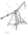
Fig. 1 zeigt in drei unterschiedlichen Ansichten einen Teil eines erfindungsgemäßen Fahrzeugkrans. Der in Fig. 1 dargestellte Teil ist Bestandteil einer für den Straßenverkehr zugelassenen ersten Transporteinheit, die einen nicht dargestellten Sattelschlepper sowie ein Fahrgestell mit einem an den Sattelschlepper koppelbaren vorderen Fahrgestellteil 23a und einem hinteren Fahrgestellteil 23b umfasst. In das Fahrgestell ist eine die beiden Fahrgestellteile 23a, 23b miteinander verbindende, topfförmige Turmaufnahme 21 fest integriert.Fig. 1 shows in three different views a part of a vehicle crane according to the invention. The part shown in Fig. 1 is part of a road transport approved first transport unit, a semitrailer, not shown, and a chassis with a coupled to the semi-trailer
Die Turmaufnahme 21, die mit einer Mehrzahl von Verbindungsstellen 41 zur Anbringung einer nachstehend näher erläuterten Turmabstützung versehen ist, dient zur Aufnahme des unteren Endes eines in Fig. 1 in seiner liegenden Transportstellung gezeigten Turmes 11. In dieser Transportstellung erstreckt sich der Turm 11 quer über die Turmaufnahme 21 hinweg und liegt auf dem Fahrgestell 23a, 23b auf.The
Der Turm 11 ist teleskopierbar und umfasst in dem hier dargestellten Ausführungsbeispiel fünf auch als Kästen oder Schüsse bezeichnete Turmsegmente 31, 33, 35, nämlich ein unteres Turmsegment oder äußeren Kasten 35 sowie vier innere Turmsegmente oder Innenkästen 31, 33, wobei das ganz oben bzw. innen liegende Turmsegment 31 an seinem freien Ende einen Kopf 45 umfasst, auf den eine in Fig. 1 nicht dargestellte Baugruppe aufsetzbar ist, die einen Ausleger umfasst und im Folgenden auch als Oberwagen bezeichnet wird.The
Zum an anderer Stelle näher beschriebenen Aufrichten des Turmes 11 dienen zwei ebenfalls nachstehend näher erläuterte Verstelleinrichtungen 27, 29.For erection of the
Eine erste Verstelleinrichtung 27 umfasst ein Kolben-/Zylinder-Paar, das zum einen am hinteren Fahrgestellteil 23b und zum anderen an einer vom unteren Turmende entfernten Stelle am unteren Turmsegment 35 angelenkt ist, und zwar in der liegenden Transportstellung an dessen vom Fahrgestell abgewandten oberen Seite.A
Eine zweite Verstelleinrichtung 29 umfasst eine sich im Wesentlichen parallel zum liegenden Turm 11 erstreckende Kolben-/Zylinder-Anordnung, deren Zylinder mit einem vorderen Ende an eine Befestigungsstelle 59 auf dem vorderen Fahrgestellteil 23a angelenkt ist. Im eingefahrenen Zustand liegt das vordere Ende 61 des Kolbens der Kolben-/Zylinder-Anordnung 29 im Bereich des hinteren Endes der Turmaufnahme 21. Über ein in Fig. 1 nicht dargestelltes, als Joch ausgebildetes Zuggestänge ist das vordere Kolbenende 61 mit dem unteren Turmende verbunden, und zwar an der in der dargestellten Transportstellung dem Fahrgestell zugewandten unteren Seite. Durch Ausfahren des Kolbens kann somit das untere Turmende nach hinten und über die Turmaufnahme 21 gezogen werden, worauf nachstehend näher eingegangen wird.A
Zum Aufrichten des Turmes 11 ist außerdem eine in Fig. 1 nicht dargestellte Halteeinrichtung in Form eines starren Lenkers vorgesehen, die ebenfalls nachstehend näher erläutert wird. Der Lenker wird mit einem Ende am vorderen Kolbenende 61 befestigt und stützt mit seinem anderen Ende den beim Aufrichten des Turmes 11 auf den Kopf 45 gesetzten Oberwagen ab.For erecting the
Für das untere Turmende ist des Weiteren eine sich im Wesentlichen horizontal erstreckende Zwangsführung 43 vorgesehen, die zwei parallel beabstandet verlaufende Schlitze oder Langlöcher umfasst, in welche das untere Turmende mit entsprechenden Führungsvorsprüngen von innen eingreift.Furthermore, a substantially horizontally extending
Fig. 2 zeigt den vorstehend erwähnten Lenker 25 im mit dem vorderen Kolbenende 61 verbundenen Zustand. Der Lenker 25 erstreckt sich parallel zum Turm 11 und ist in seinem bei zusammen geschobenem Turm 11 über den Kopf 45 hinausragenden Endbereich nach oben abgewinkelt.Fig. 2 shows the
In Fig. 2 sind außerdem vier eine Sternabstützung für den Fahrzeugkran bzw. dessen Turm 11 bildende ausfahrbare Bodenstützen 17 dargestellt. Die Bodenstützen 17 sind an den vorstehend bereits erwähnten Verbindungsstellen 41 mit der Turmaufnahme 21 verbunden. An ihren von der Turmaufnahme 21 entfernten Endbereichen sind die Bodenstützen 17 jeweils zum einen mit einem Stützfuß 49 und zum anderen mit zwei oben liegenden Winden 47 versehen, die einen z.B. auf einem Klinken- oder Rastprinzip basierenden Bremsmechanismus aufweisen. Die Winden 47 sind Bestandteil einer nachstehend näher erläuterten Turmabspannung.In Fig. 2 also four star support for the vehicle crane or its
Fig. 3 zeigt den erfindungsgemäßen Fahrzeugkran mit aufgesetztem Oberwagen 39. Der auf einem nicht dargestellten weiteren Lkw transportierte und somit einer zweiten für den Straßenverkehr zugelassenen Transporteinheit zugeordnete Oberwagen 39 weist einen Ausleger 13 auf, der einen Teleskopmast mit in diesem Ausführungsbeispiel vier Mastsegmenten 65, 67, 69 umfasst, nämlich einem oberen Mastsegment 65 mit einer nicht dargestellten Unterflasche, zwei weiteren Innensegmenten oder Innenkästen 67 sowie einem unteren Mastsegment 69, welches mit Wippwerk 55 und Drehwerk 15 verbunden ist. Zusätzlich zu dem Ausleger 13 umfasst der Oberwagen 39 in diesem Ausführungsbeispiel eine Kranführerkabine 53, die Antriebseinrichtungen für das Drehwerk 15 und das Wippwerk 55 sowie Hubwinden.Fig. 3 shows the vehicle crane according to the invention with attached
Der starre Lenker 25 ist mit dem freien Ende seines abgewinkelten Endbereiches an den hinteren Endbereich des Oberwagens 39 angelenkt.The
In der Stellung gemäß Fig. 3 ist der Oberwagen 39 lediglich einseitig mit dem Kopf 45 um eine Achse 73 schwenkbar gelenkig verbunden, so dass beim nachstehend beschriebenen Aufrichten des Turmes 11 eine Winkelverstellung zwischen Oberwagen 39 bzw. Ausleger 13 einerseits und Turm 11 andererseits möglich ist.In the position shown in FIG. 3, the
Zum Aufrichten des Turmes 11 mit aufgesetztem Oberwagen 39 wird zunächst gemäß Fig. 4 mittels der ersten Verstelleinrichtung 27 der Turm 11 aus seiner horizontalen Transportlage in die dargestellte Schräglage überführt, in welcher der Turm 11 beispielsweise etwa 45° gegenüber der Vertikalen geneigt ist. Bis hierhin ist die Aufrichtbewegung des Turmes 11 eine reine Schwenkbewegung um eine Achse 71 an dem einen Ende der Zwangsführung 43 für das untere Turmende. In der Stellung gemäß Fig. 4 befindet sich die zweite Verstelleinrichtung 29 also immer noch im eingefahrenen Zustand. In Fig. 4 ist das vorstehend bereits erwähnte, in den Fig. 1 bis 3 zumindest weitgehend verdeckte Zuggestänge bzw. Joch 81 dargestellt.For erecting the
Der starre Lenker 25 hält den Ausleger 13 trotz der sich beim Aufrichten verändernden Turmneigung stets in einer zumindest im Wesentlichen horizontalen Lage. Um für das Aufrichten des Turmes 11 günstige Kräfte- und Momentenverhältnisse zu erzielen, ist das Innensegmentpaket des Teleskopmastes des Auslegers 13 gemäß Fig. 4 ausgefahren, wodurch der Schwerpunkt des Auslegers 13 bzw. Oberwagens 39 von der Schwenkachse 73 zwischen Oberwagen 39 und Turm 11 weg nach vorne verlagert wird.The
In dem in Fig. 5 dargestellten Zustand befindet sich der Turm 11 im vollständig aufgerichteten Zustand, in welchem er sich in vertikaler Richtung erstreckt. Die Überführung des Turmes 11 aus der Schräglage gemäß Fig. 4 in die vertikale Arbeitsstellung erfolgt mittels der zweiten Verstelleinrichtung 29, die durch Ausfahren des Kolbens zum einen das untere Turmende mittels des Zuggestänges bzw. Jochs 81 auf die Turmaufnahme 21 zieht, an der das untere Turmende anschließend z.B. durch Verbolzen befestigt wird, und zum anderen das untere Ende des starren Lenkers 25 ebenfalls nach hinten - bezogen auf die Fahrtrichtung des Fahrgestells - drückt.In the state shown in Fig. 5, the
Die Lagen aller beim Aufrichten des Turmes 11 wirksamen Schwenkachsen relativ zueinander sowie die Längen aller beteiligten Bauteile sind erfindungsgemäß derart aufeinander abgestimmt, dass die Steuerbewegung, die durch den sich aufrichtenden Turm 11 über den Lenker 25 auf den verschwenkbar auf den Turm 11 aufgesetzten Oberwagen 39 übertragen wird, den Oberwagen 39 während des gesamten Aufrichtvorgangs und damit unabhängig von der Turmneigung stets in der zumindest im Wesentlichen horizontalen Solllage hält.The positions of all effective when erecting the
Nachdem der Turm 11 in die vertikale Arbeitsstellung überführt ist, wird gemäß Fig. 6 eine sternförmige Abspannung 19 installiert. Bei weiterhin zusammen geschobenem Teleskopturm 11 werden hierbei für jede der vier Bodenstützen 17 zwei Abspannseile 19, die auf die an den Bodenstützen 17 befestigten Winden 47 gewickelt sind, mit ihren freien Enden an verschiedenen Turmsegmenten befestigt, und zwar jeweils im oberen Randbereich des Segments.After the
Spanneinrichtungen zum Spannen der Seile 19 sind in die Bodenstützen 17 integriert.Clamping devices for tensioning the
Der auf die vorstehend beschriebene Weise nach dem Aufsetzen des Oberwagens 39 in die vertikale Arbeitsstellung überführte, abgestützte und abgespannte Turm 11 kann nunmehr nach Lösen der Verbindung zwischen starrem Lenker 25 und Oberwagen 39 auf die jeweils gewünschte Arbeitslänge teleskopiert werden, wie in Fig. 7a dargestellt ist. Die Abspannseile 19 werden entsprechend der zunehmenden Turmhöhe von den Winden 47 abgewickelt und können dabei ständig unter Spannung gehalten werden. Gleichzeitig mit dem Ausfahren des Turmes 11 oder nach Erreichen der jeweiligen Arbeitslänge des Turmes 11 kann der Teleskopmast des Auslegers 13 ausgefahren und mittels des Wippwerks 55 in die gewünschte Winkelstellung relativ zum Turm 11 gebracht werden, um die Mastspitze in die gewünschte Arbeitsposition bezüglich Höhe und Ausladung zu bringen.The transferred in the manner described above after placing the
Der erfindungsgemäße Fahrzeugkran ist damit einsatzbereit.The vehicle crane according to the invention is thus ready for use.
Fig. 7b zeigt schematisch den erfindungsgemäßen Fahrzeugkran in unmittelbarer Nähe eines Turmes 57 einer zu errichtenden Windkraftanlage. Ein wesentlicher Vorteil des erfindungsgemäßen Fahrzeugkrans besteht darin, dass der Kran aufgrund seines vertikalen Turmes 11 relativ nahe am Turm 57 der Windkraftanlage positioniert werden kann.Fig. 7b shows schematically the vehicle crane according to the invention in the immediate vicinity of a
Fig. 8 zeigt einen gegenüber dem vorstehend beschriebenen Ausführungsbeispiel modifizierten Fahrzeugkran, Die Modifizierung besteht in dem Vorsehen eines zusätzlichen Gegenauslegers 37. Der Gegenausleger 37 ist wie der Ausleger 13 mit einem teleskopierbaren Mast versehen und mittels eines Wippwerkes 75 relativ zum Turm 11 winkelverstellbar. Des Weiteren ist der Gegenausleger 37 mit einem von seiner Mastspitze über einen Flaschenzug herabhängenden Ballast 77 versehen.The modification consists in the provision of an
Der Gegenausleger 37 einschließlich des Ballastes 77 ist derart dimensioniert, dass er lastbedingte Biegemomente, die über den die zu hebende Last tragenden Ausleger 13 auf den Turm 11 einwirken, durch ein entsprechendes Gegenmoment kompensieren kann. Aufgrund seiner Verstellbarkeit hinsichtlich Länge und Winkel kann der Gegenausleger 37 an variierende Last- bzw. Momentensituationen auf der Auslegerseite angepasst werden.The counter-jib 37, including the
Vorzugsweise ist der erfindungsgemäße Fahrzeugkran mit einer Einrichtung versehen, die mittels einer geeigneten Sensorik die Momentanlast bzw. das Momentanmoment am Ausleger 13 ermittelt und darauf basierend den Gegenausleger 37 derart einstellt, dass der Turm 11 zumindest weitgehend biegemomentfrei gehalten, d.h. im Wesentlichen nur in vertikaler Richtung auf Druck belastet wird. Auf auslegerseitige Veränderungen kann praktisch verzögerungsfrei durch entsprechende Einstellungsveränderungen am Gegenausleger 37 reagiert werden.Preferably, the vehicle crane according to the invention is provided with a device which determines by means of a suitable sensor the instantaneous load or the instantaneous torque on the
Der Fahrzeugkran gemäß Fig. 9 unterscheidet sich von demjenigen der Fig. 8 lediglich durch das Vorsehen einer zusätzlichen Abspannung 79 zwischen dem Ausleger 13 und dem Gegenausleger 37. Die Abspannung 79 ist in Abhängigkeit von dem Winkel zwischen Ausleger 17 und Gegenausleger 37 längenveränderlich, und zwar mittels eines separaten Flaschenzuges am Gegenausleger 37. Durch die Abspannung 79 werden die Wippwerke 55, 75 entlastet.The vehicle crane according to FIG. 9 differs from that of FIG. 8 only by the provision of an additional bracing 79 between the
Die Ausladung des erfindungsgemäßen Fahrzeugkranes kann wegen des vertikalen Turmes 11 auf das für den jeweiligen Hebejob erforderliche Maß und damit auf das notwendige Minimum beschränkt werden. Damit ist der erfindungsgemäße Fahrzeugkran frei von einer bei herkömmlichen Fahrzeugkranen erforderlichen Zwangsausladung. Dies ermöglicht es, das Eigengewicht des Turmes 11 als Zentralballast zu verwenden, auf das bei herkömmlichen Fahrzeugkranen übliche Gegengewicht zumindest teilweise zu verzichten und gegebenenfalls für die Abstützung 17 des Turmes 11 nur ein vergleichsweise geringes Gegengewicht vorzusehen. Das erfindungsgemäße Obendreher-Konzept ermöglicht das Vorsehen der Abspannung 19, durch welche die Belastbarkeit des Turmes 11 hinsichtlich der tolerierbaren Biegemomente erhöht wird, was wiederum zusätzliche Gewichte überflüssig macht. Die durch den vertikalen Turm 17 selbst bereits vorhandene Standsicherheit erfordert - wenn überhaupt - nur ein vergleichsweise geringes Gegengewicht für die Abstützung 17 des Turmes 11.The projection of the vehicle crane according to the invention can be limited to the required level for the respective lifting job and thus to the necessary minimum because of the
Die Erfindung schafft damit einen Fahrzeugkran, der bezogen auf seine Tragkraft bzw. Hebekapazität ein niedriges Gesamtgewicht und einen geringen Platzbedarf aufweist und dadurch vergleichsweise schnell und einfach im Straßenverkehr bewegt und am Einsatzort betriebsbereit gemacht werden kann. Dies resultiert in einer enormen Reduzierung der Krannutzungskosten.The invention thus provides a vehicle crane, which in terms of its capacity or lifting capacity has a low overall weight and a small footprint and thus relatively quickly and easily moved in the street and can be made operational on site. This results in a huge reduction in Krusutzungskosten.
Der erfindungs gemäße Fahrzeugkran ist hinsichtlich seiner Auslegung insbesondere in Bezug auf die Abmessungen und das Gewicht seiner Bestandteile grundsätzlich beliebig skalierbar. Vorzugsweise ist der erfindungsgemäße Fahrzeugkran so ausgelegt, dass er für die Errichtung von Windkraftanlagen geeignet ist.The fiction, contemporary vehicle crane is in principle arbitrarily scalable in terms of its interpretation, in particular with respect to the dimensions and weight of its components. Preferably, the vehicle crane according to the invention is designed so that it is suitable for the construction of wind turbines.
Für die Errichtung von derzeit bereits existierenden Windkraftanlagen, die eine Nabenhöhe von etwa 85 100m aufweisen und bei denen die zu hebenden Lasten bis zu etwa 52t betragen, ist gemäß einem möglichen Ausführungsbeispiel vorgesehen, dass der Turm 11 ein Gewicht von ungefähr 60t und eine Länge im ausgefahrenen Zustand von ungefähr 70m aufweist, wobei der Oberwagen 39 ein Gewicht von ungefähr 60t und dessen Ausleger 13 im ausgefahrenen Zustand eine Länge von etwa 60m besitzt. Die Stützweite der sternförmigen Abstützung 17, d.h. die Länge der Bodenstützen im ausgefahrenen Zustand, beträgt dabei jeweils etwa 18m.For the construction of currently existing wind turbines, which have a hub height of about 85 100m and in which the loads to be lifted are up to about 52t, it is provided according to a possible embodiment that the
Zukünftige Windkraftanlagen werden gemäß bereits existierenden Planungen eine Nabenhöhe von ungefähr 145m und zu hebende Lasten in der Größenordnung von 240t aufweisen. Auch derartige Windkraftanlagen können mit einem gegenüber der vorstehend erwähnten Auslegung entsprechend vergrößerten erfindungsgemäßen Fahrzeugkran problemlos aufgestellt werden. Gegebenenfalls wird hierfür die Variante mit Gegenausleger 37 gemäß Fig. 8 oder 9 zum Einsatz kommen.Future wind turbines will have a hub height of about 145m and lifting loads on the order of 240t, according to existing plans. Also, such wind turbines can be easily installed with a relation to the above-mentioned interpretation according to the invention enlarged vehicle crane. If necessary, this variant with
- 1111
- Turmtower
- 1313
- Auslegerboom
- 1515
- Drehwerkslewing
- 1717
- Abstützung, BodenstützeSupport, floor support
- 1919
- Abspannung, AbspannseilBracing, guy rope
- 2121
- Turmaufnahmetower admission
- 23a23a
- vorderes Fahrgestellteilfront chassis part
- 23b23b
- hinteres Fahrgestellteilrear chassis part
- 2525
- Halteeinrichtung, starrer LenkerHolding device, rigid handlebar
- 2727
- erste Verstelleinrichtungfirst adjusting device
- 2929
- zweite Verstelleinrichtungsecond adjustment
- 3131
- oberes TurmsegmentUpper tower segment
- 3333
- Zwischensegment des TurmesIntermediate segment of the tower
- 3535
- unteres Turmsegmentlower tower segment
- 3737
- Gegenauslegercounter-jib
- 3939
- Oberwagensuperstructure
- 4141
- Verbindungsstellejunction
- 4343
- Zwangsführungforced control
- 4545
- Kopfhead
- 4747
- Winde mit BremsmechanismusWinch with brake mechanism
- 4949
- StützfußSupport foot
- 5353
- Kabinecabin
- 5555
- WippwerkBoom elevation
- 5757
- Turm einer WindkraftanlageTower of a wind turbine
- 5959
- Befestigungsstellefastening point
- 6161
- vorderes Kolbenendefront piston end
- 6565
- oberes Mastsegmentupper pole segment
- 6767
- Zwischensegment des AuslegermastesIntermediate segment of the jib
- 6969
- unteres Mastsegmentlower pole segment
- 7171
- Schwenkachse für unteres TurmendeSwivel axis for lower tower end
- 7373
- Schwenkachse zwischen Ausleger und TurmSwivel axis between boom and tower
- 7575
- WippwerkBoom elevation
- 7777
- Ballastballast
- 7979
- Abspannungguying
- 8181
- Zuggestänge, JochDrawbar, yoke
Claims (19)
mit einem als Obendreher ausgebildeten Aufbau, der einen vertikalen Turm (11) und auf dem Turm (11) einen Ausleger (13) umfasst,
dadurch gekennzeichnet,
dass für das untere Ende des Turmes (11) eine insbesondere topf- oder napfförmige Turmaufnahme (21) vorgesehen ist, die zwei beabstandete Fahrgestellteile (23a, 23b) miteinander verbindet, wobei vorzugsweise bei in Transportlage befindlichem Turm (11) dessen unteres Ende von der Turmaufnahme (21) getrennt ist.Mobile crane, in particular mobile, car or crawler crane,
with a top-sleeved structure comprising a vertical tower (11) and a jib (13) on the tower (11),
characterized,
that for the lower end of the tower (11) a particular cup or cup-shaped tower receptacle (21) is provided, the two spaced chassis parts (23a, 23b) interconnected, preferably in befindlichem in transport position tower (11) whose lower end of the Tower receptacle (21) is disconnected.
dadurch gekennzeichnet,
dass die Turmaufnahme (21) mit einer Turmabstützung (17) verbunden ist.Vehicle crane according to claim 1,
characterized,
in that the tower receptacle (21) is connected to a tower support (17).
dadurch gekennzeichnet,
dass der Turm (11) selbstaufrichtend ausgebildet ist.Vehicle crane according to claim 1 or 2,
characterized,
that the tower (11) is self-erecting.
dadurch gekennzeichnet,
dass zum Aufrichten des Turmes (11) wenigstens zwei längenveränderliche Verstelleinrichtungen (27, 29) vorgesehen sind, die an längs des Turmes (11) beabstandeten Positionen angreifen.Vehicle crane according to one of the preceding claims,
characterized,
in that at least two variable-length adjustment devices (27, 29) are provided for erecting the tower (11), which engage at positions spaced along the tower (11).
dadurch gekennzeichnet,
dass der Turm (11) mittels einer mit Abstand vom unteren Turmende angreifenden ersten Verstelleinrichtung (27) aus einer im Wesentlichen horizontalen Transportlage in eine Schräglage und mittels einer im Bereich des unteren Turmendes angreifenden zweiten Verstelleinrichtung (29) aus der Schräglage in die vertikale Arbeitsstellung überführbar ist, wobei vorzugsweise der Turm (11) im Bereich seines unteren Endes zwangsgeführt ist.Vehicle crane according to one of the preceding claims,
characterized,
that the tower (11) by means of a first adjusting device (27) engaging at a distance from the lower tower end from a substantially horizontal transport position in an inclined position and by means of a attacking in the region of the lower tower end second adjusting device (29) from the inclined position into the vertical working position can be transferred, wherein preferably the tower (11) is positively guided in the region of its lower end.
dadurch gekennzeichnet,
dass der Turm (11) mit aufgesetztem Ausleger (13), insbesondere den Ausleger (13) umfassendem Oberwagen (39), aufrichtbar ist.Vehicle crane according to one of the preceding claims,
characterized,
that the tower (11) can be erected with an attached arm (13), in particular the upper arm (39) comprising the arm (13).
dadurch gekennzeichnet,
dass eine insbesondere als starrer Lenker ausgebildete Halteeinrichtung (25) vorgesehen ist, die den winkelverstellbar auf den Turm (11) aufgesetzten Ausleger (13) beim Aufrichten unabhängig von der Turmneigung in einer zumindest näherungsweise horizontalen Lage hält.Vehicle crane according to one of the preceding claims,
characterized,
in that a holding device (25) designed in particular as a rigid link is provided, which holds the jib (13) mounted on the tower (11) in an at least approximately horizontal position when erecting, regardless of the inclination of the tower.
dadurch gekennzeichnet,
dass der Ausleger (13) gegenüber dem Turm (11) geneigt ist.Vehicle crane according to one of the preceding claims,
characterized,
that the boom (13) is inclined relative to the tower (11).
dadurch gekennzeichnet,
dass der Ausleger (13) längenveränderlich, vorzugsweise teleskopierbar, und/oder relativ zum Turm (11) winkelverstellbar ist.Vehicle crane according to one of the preceding claims,
characterized,
that the boom (13) variable in length, preferably telescopic, and / or relative to the tower (11) is angularly adjustable.
dadurch gekennzeichnet,
dass der Turm (11) längenveränderlich, vorzugsweise teleskopierbar ist.Vehicle crane according to one of the preceding claims,
characterized,
that the tower (11) is variable in length, preferably telescopic.
dadurch gekennzeichnet,
dass das Eigengewicht des Turmes (11) als Gegengewicht vorgesehen ist.Vehicle crane according to one of the preceding claims,
characterized,
that the weight of the tower (11) is provided as a counterweight.
dadurch gekennzeichnet,
dass für den Turm (11) eine Abstützung (17) vorgesehen ist, die vorzugsweise eine Mehrzahl von um den Turm (11) herum verteilten Bodenstützen umfasst.Vehicle crane according to one of the preceding claims,
characterized,
that the tower (11) a support (17) is provided, which is preferably of the tower (11) around includes a plurality of distributed base supports.
dadurch gekennzeichnet,
dass das Eigengewicht des Turmes (11) und die Abstützung (17) derart aufeinander abgestimmt sind, dass kein zusätzliches Gegengewicht erforderlich ist.Vehicle crane according to claim 12,
characterized,
that the weight of the tower (11) and the support (17) are coordinated so that no additional counterweight is required.
dadurch gekennzeichnet,
dass für den Turm (11) eine Abspannung (19) vorgesehen ist, die vorzugsweise eine Mehrzahl von um den Turm (11) herum verteilten Abspannorganen umfasst.Vehicle crane according to one of the preceding claims,
characterized,
in that a bracing (19) is provided for the tower (11), which preferably comprises a plurality of bracing elements distributed around the tower (11).
dadurch gekennzeichnet,
dass der Turm (11) teleskopierbar ist und die Abspannung (19) an einem oder mehreren Turmsegmenten (31, 33, 35) angreift.Vehicle crane according to claim 14,
characterized,
that the tower (11) is telescopic and the bracing (19) acts on one or more tower segments (31, 33, 35).
dadurch gekennzeichnet,
dass die Abspannung (19) zumindest zum Teil an einer Turmabstützung (17) verankert ist.Vehicle crane according to claim 14 or 15,
characterized,
that the bracing (19) is at least partially anchored to a tower support (17).
dadurch gekennzeichnet,
dass der Ausleger (13) mit einem Gegenausleger (37) versehen ist, wobei vorzugsweise der Gegenausleger (37) zum Verändern des durch ihn auf den Turm (11) einwirkenden Biegemomentes einstellbar und insbesondere längenveränderlich, bevorzugt teleskopierbar, und/ oder relativ zum Turm (11) winkelverstellbar ist.Vehicle crane according to one of the preceding claims,
characterized,
in that the jib (13) is provided with a counterjib (37), wherein preferably the counter jib (37) is adjustable and in particular variable in length, preferably telescopic, and / or relative to the tower (14) for changing the bending moment acting on the tower (11). 11) is adjustable in angle.
dadurch gekennzeichnet,
dass lastbedingte Biegemomente mittels des Gegenauslegers (37) kompensierbar sind, bevorzugt derart, dass der Turm (11) zumindest weitgehend biegemomentfrei ist, wobei vorzugsweise eine Steuer- und/oder Regeleinrichtung vorgesehen ist, mittels welcher der Gegenausleger (37) in Abhängigkeit vom Momentanlastmoment einstellbar ist.Vehicle crane according to claim 17,
characterized,
in that load-induced bending moments can be compensated by means of the counter-jib (37), preferably such that the tower (11) is at least largely free of bending moment, preferably a control and / or regulating device being provided by means of which the counter-jib (37) can be adjusted as a function of the instantaneous load torque is.
dadurch gekennzeichnet,
dass der auf einem insbesondere als Tieflader ausgebildeten Fahrgestell (23a, 23b) angeordnete Turm (11) einerseits und der Ausleger (13), insbesondere ein den Ausleger (13) umfassender Oberwagen (39), andererseits separaten, insbesondere jeweils für den Strassentransport zugelassenen Transporteinheiten zugeordnet sind.Vehicle crane according to one of the preceding claims,
characterized,
in that the tower (11) arranged on a chassis (23a, 23b) designed in particular as a low loader, on the one hand, and the jib (13), in particular a superstructure (39) comprising the jib (13), on the other hand separate transport units admitted in each case for road transport assigned.
Priority Applications (1)
| Application Number | Priority Date | Filing Date | Title |
|---|---|---|---|
| DE502004011669T DE502004011669D1 (en) | 2004-12-03 | 2004-12-03 | mobile crane |
Applications Claiming Priority (1)
| Application Number | Priority Date | Filing Date | Title |
|---|---|---|---|
| EP04028739A EP1666401B1 (en) | 2004-12-03 | 2004-12-03 | Mobile crane |
Related Parent Applications (2)
| Application Number | Title | Priority Date | Filing Date |
|---|---|---|---|
| EP04028739.3 Division | 2004-12-03 | ||
| EP04028739A Division EP1666401B1 (en) | 2004-12-03 | 2004-12-03 | Mobile crane |
Publications (3)
| Publication Number | Publication Date |
|---|---|
| EP1894883A2 true EP1894883A2 (en) | 2008-03-05 |
| EP1894883A3 EP1894883A3 (en) | 2008-05-28 |
| EP1894883B1 EP1894883B1 (en) | 2010-09-15 |
Family
ID=34927650
Family Applications (3)
| Application Number | Title | Priority Date | Filing Date |
|---|---|---|---|
| EP07116453A Expired - Fee Related EP1900675B1 (en) | 2004-12-03 | 2004-12-03 | Crane truck |
| EP07116452A Expired - Fee Related EP1894883B1 (en) | 2004-12-03 | 2004-12-03 | Crane vehicle |
| EP04028739A Expired - Fee Related EP1666401B1 (en) | 2004-12-03 | 2004-12-03 | Mobile crane |
Family Applications Before (1)
| Application Number | Title | Priority Date | Filing Date |
|---|---|---|---|
| EP07116453A Expired - Fee Related EP1900675B1 (en) | 2004-12-03 | 2004-12-03 | Crane truck |
Family Applications After (1)
| Application Number | Title | Priority Date | Filing Date |
|---|---|---|---|
| EP04028739A Expired - Fee Related EP1666401B1 (en) | 2004-12-03 | 2004-12-03 | Mobile crane |
Country Status (9)
| Country | Link |
|---|---|
| US (2) | US7828162B2 (en) |
| EP (3) | EP1900675B1 (en) |
| JP (3) | JP2008532876A (en) |
| KR (4) | KR101046519B1 (en) |
| CN (2) | CN101068744B (en) |
| CA (1) | CA2589048C (en) |
| DE (2) | DE502004011788D1 (en) |
| ES (3) | ES2367908T3 (en) |
| WO (1) | WO2006058751A2 (en) |
Families Citing this family (38)
| Publication number | Priority date | Publication date | Assignee | Title |
|---|---|---|---|---|
| ES1066342Y (en) * | 2007-10-22 | 2008-04-01 | Gruas Y Transportes Caba S L | "MOBILE SUPPORT ASSEMBLY" |
| DE102008032739B4 (en) * | 2008-01-25 | 2021-10-21 | Liebherr-Werk Ehingen Gmbh | Mobile crane and method of assembly |
| US9284168B2 (en) * | 2009-10-01 | 2016-03-15 | Mw Industries, Inc. | Guyless service rig with side-mounted, pivotally deployable rear outriggers |
| CN101746675B (en) * | 2009-12-31 | 2012-05-02 | 三一汽车制造有限公司 | Crane super lifting device, control system and control method thereof |
| US8621954B1 (en) * | 2010-06-04 | 2014-01-07 | University Of Washington Through Its Center For Commercialization | Systems and methods for gravity compensation |
| US8882441B2 (en) | 2010-07-07 | 2014-11-11 | ATOPIA Research | Deployable wind power and battery unit |
| CN102452616B (en) * | 2010-10-20 | 2013-06-19 | 徐州重型机械有限公司 | Landing leg support device and movable crane |
| US8678210B1 (en) * | 2010-11-17 | 2014-03-25 | Link-Belt Construction Equipment Co., L.P., Lllp | Telescoping boom assembly with base section having primary shell and secondary formed shell |
| DE102010056584B4 (en) * | 2010-12-30 | 2018-03-29 | Asm Automation Sensorik Messtechnik Gmbh | Mobile work machine |
| JP5746870B2 (en) * | 2011-01-20 | 2015-07-08 | 株式会社加藤製作所 | Crane equipment |
| MX2013012043A (en) * | 2011-04-14 | 2014-05-27 | Mantenimientos Eléctricos Campo De Aviación S L | Repair/cleaning scaffolding tower for wind turbines. |
| CN102259799B (en) * | 2011-05-05 | 2012-12-05 | 中联重科股份有限公司 | Torque control method and device for crawler crane installation, and crawler crane |
| CN102431909B (en) * | 2011-11-08 | 2013-08-07 | 中联重科股份有限公司 | Connection structure of outrigger and frame body in crane |
| DE102013009357A1 (en) * | 2012-06-11 | 2013-12-12 | Liebherr-Werk Ehingen Gmbh | Modular mobile crane |
| CN102826447B (en) * | 2012-09-06 | 2015-02-18 | 三一重工股份有限公司 | Truss jib crane as well as getting-off structure and position transferring method thereof |
| US9327947B2 (en) * | 2012-11-26 | 2016-05-03 | Mickel Davis | All-terrain vehicle lifting crane apparatus |
| US9139409B2 (en) | 2013-03-12 | 2015-09-22 | Oshkosh Corporation | Weighted boom assembly |
| CN103274313B (en) * | 2013-06-08 | 2015-03-04 | 中石化第十建设有限公司 | Tail suspending apparatus |
| DE102013011489B4 (en) * | 2013-07-09 | 2021-09-16 | Liebherr-Werk Ehingen Gmbh | Tower crane |
| CN104495637B (en) * | 2014-12-16 | 2016-10-05 | 中联重科股份有限公司 | Crane self-disassembling device, crane and from method for dismounting |
| CN104647367B (en) * | 2014-12-29 | 2016-05-25 | 合肥工业大学 | The robot palletizer in parallel of the compound driving of a kind of rope bar |
| DE102015103556A1 (en) * | 2015-03-11 | 2016-09-15 | Manitowoc Crane Group France Sas | Device and method for determining the ground pressure distribution in a mobile work machine |
| DE102015003982A1 (en) | 2015-03-26 | 2016-09-29 | Liebherr-Werk Biberach Gmbh | crane tower |
| US10106378B2 (en) | 2015-11-03 | 2018-10-23 | General Electric Company | System and method for lifting with load moving machine |
| FR3046149B1 (en) * | 2015-12-23 | 2017-12-29 | Manitowoc Crane Group France | AUTOMATICALLY FOLDING AND FOLDING CRANE COMPRISING A MAT AND ARROW DECALED FROM MATERIAL |
| CN105645278B (en) * | 2016-03-31 | 2017-09-01 | 中冶建工集团有限公司 | The installation method of crawler crane in side slope place |
| CN106088623A (en) * | 2016-07-29 | 2016-11-09 | 上海市政建设有限公司 | Utilize flooring or the construction method of roofing enforcement lifting of building structure |
| DE102016114837A1 (en) | 2016-08-10 | 2018-02-15 | Terex Global Gmbh | Telescopic boom with guy system for a mobile crane and guying system |
| CN106241622B (en) * | 2016-08-15 | 2018-06-19 | 宁波建工建乐工程有限公司 | Mobile crane |
| CN106348214A (en) * | 2016-10-08 | 2017-01-25 | 苏州威尔特铝合金升降机械有限公司 | Mast type high-altitude operation platform support state positioning system |
| DE102017101113B3 (en) * | 2017-01-20 | 2018-07-12 | Terex Global Gmbh | Telescopic boom with pole tensioning system for a mobile crane and guying method |
| US10240339B1 (en) * | 2017-11-16 | 2019-03-26 | Eddy Dominguez | Mobile cellular transmission system |
| WO2020091090A1 (en) * | 2018-10-29 | 2020-05-07 | 엄부섭 | Tower crane having improved safety |
| CN109534182B (en) * | 2018-11-09 | 2022-12-09 | 湖南维尔力德科技有限公司 | Movable fast assembling crane |
| CN110759254A (en) * | 2019-11-12 | 2020-02-07 | 中国人民解放军火箭军工程大学 | Crane suitable for roadway hoisting |
| NL2030208B1 (en) * | 2021-12-21 | 2023-06-29 | Itrec Bv | Erecting a self-climbing tower crane |
| WO2023118352A1 (en) * | 2021-12-21 | 2023-06-29 | Itrec B.V. | A self-climbing tower crane |
| CN116395581B (en) * | 2023-06-08 | 2023-08-11 | 济宁市特种设备检验研究院 | Upright post reinforcing device of cantilever crane |
Citations (4)
| Publication number | Priority date | Publication date | Assignee | Title |
|---|---|---|---|---|
| FR1434262A (en) | 1965-02-15 | 1966-04-08 | Richier Sa | Method and mechanism for developing and folding the tower of a building crane |
| DE1267394B (en) | 1961-06-01 | 1968-05-02 | Albert William Hobbs | Mobile tower crane |
| DE2748340A1 (en) | 1976-10-29 | 1978-05-11 | Ishikawajima Harima Heavy Ind | Tower crane with detachable tower - has struts and end connection on climbing frame for ready dismantling from base |
| JP2004224520A (en) | 2003-01-24 | 2004-08-12 | Ishikawajima Constr Mach Co | Self-travelling tower crane |
Family Cites Families (39)
| Publication number | Priority date | Publication date | Assignee | Title |
|---|---|---|---|---|
| BE504079A (en) * | ||||
| US2143111A (en) * | 1937-07-12 | 1939-01-10 | Hayes Econocrete Corp | Portable crane |
| DE759687C (en) * | 1939-10-17 | 1954-06-28 | Ardeltwerke | For the heaviest loads, it can be dismantled and easily erected |
| US2639825A (en) * | 1947-05-06 | 1953-05-26 | Lourie L Eakin | Vehicle-mounted hoisting apparatus |
| US2544553A (en) * | 1947-12-19 | 1951-03-06 | Lourie L Eakin | Hoist mechanism |
| US2857994A (en) * | 1954-03-08 | 1958-10-28 | Patent Scaffolding Co Inc | Erection frames for sectional towers |
| DE1205674B (en) * | 1962-04-25 | 1965-11-25 | Richier Sa | Tower crane |
| FR1586854A (en) * | 1968-04-23 | 1970-03-06 | ||
| US3938670A (en) * | 1969-04-09 | 1976-02-17 | General Crane Industries Limited | Tower crane |
| GB1404136A (en) * | 1971-11-04 | 1975-08-28 | Gen Crane Industries | Mobile load holding means particularly tower cranes |
| GB1404135A (en) * | 1971-11-04 | 1975-08-28 | Gen Crane Industries | Telescopic structures particularly tower cranes |
| GB1374255A (en) * | 1972-05-03 | 1974-11-20 | Gen Crane Industries | Mobile tower cranes |
| JPS5410141Y2 (en) * | 1973-12-28 | 1979-05-11 | ||
| JPS5757314A (en) * | 1980-09-22 | 1982-04-06 | Komatsu Ltd | Leader angle controller |
| IT8120651V0 (en) * | 1981-02-02 | 1981-02-02 | Stilgru S R L | STRUCTURE OF A BUILDING TOWER CRANE. |
| DE3139596A1 (en) * | 1981-10-05 | 1983-04-21 | Liebherr-Werk Ehingen Gmbh, 7930 Ehingen | HEAVY DUTY TELESCOPIC CRANE |
| DE3150282A1 (en) * | 1981-12-18 | 1983-06-30 | Liebherr-Werk Biberach Gmbh, 7950 Biberach | Underbody for a crane |
| FR2534237B1 (en) * | 1982-10-12 | 1987-10-23 | Krupp Gmbh | HIGH-STRENGTH ROLLING CRANE WITH EXTENDABLE BOOM, ESPECIALLY WITH TELESCOPIC BOOM |
| DE3307892C2 (en) * | 1983-03-05 | 1986-09-11 | Pekazett Baumaschinen GmbH, 6660 Zweibrücken | Tower crane with jib and counter jib |
| SU1118601A1 (en) * | 1983-03-31 | 1984-10-15 | Специальное конструкторское бюро "СКБ-Мосстрой" | Method of erecting tower crane |
| DE3441655A1 (en) * | 1984-11-14 | 1986-05-15 | Liebherr-Werk Bischofshofen GmbH, Bischofshofen | Tower which can be quickly erected for cranes, lifts or the like, preferably for antennas |
| JPS61165991U (en) * | 1985-04-05 | 1986-10-15 | ||
| US4625475A (en) * | 1985-05-13 | 1986-12-02 | Mcginnis Henry J | Extensible mast |
| US4846357A (en) * | 1987-06-15 | 1989-07-11 | Paxton-Mitchell Company | Offshore station articulated boom maintenance unit |
| US4944364A (en) * | 1989-04-24 | 1990-07-31 | Asplundh Tree Expert Co. | Boom elevating device for line lifts |
| US5025606A (en) * | 1989-04-27 | 1991-06-25 | Rapid Deployment Towers, Inc. | Guy control system for extensible mast |
| JP2841016B2 (en) * | 1993-11-08 | 1998-12-24 | 小松メック株式会社 | Operation control method and device for reach tower crane |
| JP2912958B2 (en) * | 1993-12-16 | 1999-06-28 | 株式会社小松製作所 | Mobile tower crane |
| JPH084303A (en) * | 1994-06-17 | 1996-01-09 | Kobe Steel Ltd | Construction method of building |
| CN2247650Y (en) * | 1995-03-07 | 1997-02-19 | 桂林市建工机械厂 | Collapsible tower crane |
| DE19731049B4 (en) * | 1997-07-21 | 2013-04-11 | Abcranessolutions Gmbh | Crane with bridge jib |
| KR100310991B1 (en) * | 1999-05-31 | 2001-10-17 | 임종남 | assembly type tower crane for power transmission tower |
| DE10022658B4 (en) * | 1999-06-28 | 2007-10-04 | Terex-Demag Gmbh & Co. Kg | telescopic crane |
| DE19938578A1 (en) * | 1999-08-18 | 2001-02-22 | Delmag Maschinenfabrik | Mobile working device |
| EP1188707A1 (en) * | 2000-09-18 | 2002-03-20 | Karl Schaeff GmbH & Co. Maschinenfabrik | Material handling device |
| DE10315989B4 (en) * | 2003-04-08 | 2007-10-25 | Grove U.S. Llc | Clamping system for a mobile telescopic crane |
| EP1613859B8 (en) * | 2003-04-15 | 2013-01-09 | Vestas Wind Systems A/S | Method of servicing the outer components of a wind turbine such as the wind turbine blades and the tower with a work platform and work platform |
| JP4402923B2 (en) * | 2003-09-10 | 2010-01-20 | 株式会社タダノ | Tower crane |
| US7341158B2 (en) * | 2004-01-09 | 2008-03-11 | Kobelco Cranes Co., Ltd. | Traveling crane and assembling/disassembling method thereof |
-
2004
- 2004-12-03 ES ES04028739T patent/ES2367908T3/en active Active
- 2004-12-03 ES ES07116452T patent/ES2352807T3/en active Active
- 2004-12-03 DE DE502004011788T patent/DE502004011788D1/en active Active
- 2004-12-03 EP EP07116453A patent/EP1900675B1/en not_active Expired - Fee Related
- 2004-12-03 DE DE502004011669T patent/DE502004011669D1/en active Active
- 2004-12-03 ES ES07116453T patent/ES2354178T3/en active Active
- 2004-12-03 EP EP07116452A patent/EP1894883B1/en not_active Expired - Fee Related
- 2004-12-03 EP EP04028739A patent/EP1666401B1/en not_active Expired - Fee Related
-
2005
- 2005-12-01 KR KR1020097015617A patent/KR101046519B1/en not_active IP Right Cessation
- 2005-12-01 CN CN2005800414114A patent/CN101068744B/en not_active Expired - Fee Related
- 2005-12-01 KR KR1020097015618A patent/KR101046490B1/en not_active IP Right Cessation
- 2005-12-01 CN CN201310447271.7A patent/CN103482489B/en not_active Expired - Fee Related
- 2005-12-01 WO PCT/EP2005/012852 patent/WO2006058751A2/en active Application Filing
- 2005-12-01 CA CA2589048A patent/CA2589048C/en not_active Expired - Fee Related
- 2005-12-01 KR KR1020077015310A patent/KR20070086923A/en not_active Application Discontinuation
- 2005-12-01 KR KR1020097015616A patent/KR101046488B1/en not_active IP Right Cessation
- 2005-12-01 US US11/792,062 patent/US7828162B2/en not_active Expired - Fee Related
- 2005-12-01 JP JP2007543778A patent/JP2008532876A/en active Pending
-
2009
- 2009-12-31 US US12/651,015 patent/US8308000B2/en active Active
-
2011
- 2011-05-30 JP JP2011119957A patent/JP5572125B2/en not_active Expired - Fee Related
- 2011-05-30 JP JP2011119956A patent/JP5572124B2/en not_active Expired - Fee Related
Patent Citations (4)
| Publication number | Priority date | Publication date | Assignee | Title |
|---|---|---|---|---|
| DE1267394B (en) | 1961-06-01 | 1968-05-02 | Albert William Hobbs | Mobile tower crane |
| FR1434262A (en) | 1965-02-15 | 1966-04-08 | Richier Sa | Method and mechanism for developing and folding the tower of a building crane |
| DE2748340A1 (en) | 1976-10-29 | 1978-05-11 | Ishikawajima Harima Heavy Ind | Tower crane with detachable tower - has struts and end connection on climbing frame for ready dismantling from base |
| JP2004224520A (en) | 2003-01-24 | 2004-08-12 | Ishikawajima Constr Mach Co | Self-travelling tower crane |
Also Published As
Similar Documents
| Publication | Publication Date | Title |
|---|---|---|
| EP1666401B1 (en) | Mobile crane | |
| DE10022600B4 (en) | telescopic crane | |
| DE10315989B4 (en) | Clamping system for a mobile telescopic crane | |
| EP0354167B1 (en) | Crane, especially a crane for heavy loads | |
| EP2248754B1 (en) | Telescopic crane with self-fittable bracing device and fitting method for a bracing device | |
| DE102013011489A1 (en) | Tower Crane | |
| EP3132137B1 (en) | Mobile crane device and method for the temporary assembly of such a crane device | |
| WO2002100756A1 (en) | Mobile crane comprising a telescopic principal jib | |
| DE102021109113A1 (en) | Mobile crane and method of reducing the load on its boom | |
| EP3793930B1 (en) | Support for the rear anchoring line of a telescopic crane | |
| DE102018115632B3 (en) | Telescopic boom bracing device | |
| EP2377804B1 (en) | Mobile crane, in particular mobile construction crane | |
| DE202013011183U1 (en) | Telescopic super lift mast | |
| DE2931422C3 (en) | Top slewing tower crane | |
| DE202004013077U1 (en) | Vehicle crane for lifting objects has base arm, which is detachably connected to main arm whereby one or two tightening supports are arranged on base arm | |
| DE102019122071B3 (en) | Telescopic boom with fold-out mast | |
| DE102022126929B3 (en) | Mobile crane with a removable telescopic boom and method for erecting a structure | |
| DE102019131914B4 (en) | Crane with luffing boom extension | |
| EP2984024B1 (en) | Folding crane jib and crane | |
| DE102020107549B3 (en) | Method for erecting a jib of a large crane | |
| DE102022122282A1 (en) | Mobile crane with a detachable attached superstructure and setup process for this | |
| EP3730448A1 (en) | Mobile crane with extendable guy mast | |
| EP3943438A1 (en) | Mobile crane with separable a frame | |
| DE3441655A1 (en) | Tower which can be quickly erected for cranes, lifts or the like, preferably for antennas | |
| DE3401094A1 (en) | CRANE WITH TELESCOPIC TOWER |
Legal Events
| Date | Code | Title | Description |
|---|---|---|---|
| PUAI | Public reference made under article 153(3) epc to a published international application that has entered the european phase |
Free format text: ORIGINAL CODE: 0009012 |
|
| 17P | Request for examination filed |
Effective date: 20070914 |
|
| AC | Divisional application: reference to earlier application |
Ref document number: 1666401 Country of ref document: EP Kind code of ref document: P |
|
| AK | Designated contracting states |
Kind code of ref document: A2 Designated state(s): AT BE BG CH CY CZ DE DK EE ES FI FR GB GR HU IE IS IT LI LT LU MC NL PL PT RO SE SI SK TR |
|
| PUAL | Search report despatched |
Free format text: ORIGINAL CODE: 0009013 |
|
| AK | Designated contracting states |
Kind code of ref document: A3 Designated state(s): AT BE BG CH CY CZ DE DK EE ES FI FR GB GR HU IE IS IT LI LT LU MC NL PL PT RO SE SI SK TR |
|
| 17Q | First examination report despatched |
Effective date: 20080704 |
|
| AKX | Designation fees paid |
Designated state(s): DE ES FR GB IT |
|
| GRAP | Despatch of communication of intention to grant a patent |
Free format text: ORIGINAL CODE: EPIDOSNIGR1 |
|
| GRAS | Grant fee paid |
Free format text: ORIGINAL CODE: EPIDOSNIGR3 |
|
| GRAA | (expected) grant |
Free format text: ORIGINAL CODE: 0009210 |
|
| AC | Divisional application: reference to earlier application |
Ref document number: 1666401 Country of ref document: EP Kind code of ref document: P |
|
| AK | Designated contracting states |
Kind code of ref document: B1 Designated state(s): DE ES FR GB IT |
|
| REG | Reference to a national code |
Ref country code: GB Ref legal event code: FG4D Free format text: NOT ENGLISH |
|
| REF | Corresponds to: |
Ref document number: 502004011669 Country of ref document: DE Date of ref document: 20101028 Kind code of ref document: P |
|
| REG | Reference to a national code |
Ref country code: ES Ref legal event code: FG2A Effective date: 20110211 |
|
| PLBE | No opposition filed within time limit |
Free format text: ORIGINAL CODE: 0009261 |
|
| STAA | Information on the status of an ep patent application or granted ep patent |
Free format text: STATUS: NO OPPOSITION FILED WITHIN TIME LIMIT |
|
| 26N | No opposition filed |
Effective date: 20110616 |
|
| REG | Reference to a national code |
Ref country code: DE Ref legal event code: R097 Ref document number: 502004011669 Country of ref document: DE Effective date: 20110616 |
|
| REG | Reference to a national code |
Ref country code: FR Ref legal event code: PLFP Year of fee payment: 12 |
|
| PGFP | Annual fee paid to national office [announced via postgrant information from national office to epo] |
Ref country code: GB Payment date: 20151221 Year of fee payment: 12 |
|
| PGFP | Annual fee paid to national office [announced via postgrant information from national office to epo] |
Ref country code: ES Payment date: 20151222 Year of fee payment: 12 |
|
| PGFP | Annual fee paid to national office [announced via postgrant information from national office to epo] |
Ref country code: IT Payment date: 20151228 Year of fee payment: 12 |
|
| REG | Reference to a national code |
Ref country code: FR Ref legal event code: PLFP Year of fee payment: 13 |
|
| GBPC | Gb: european patent ceased through non-payment of renewal fee |
Effective date: 20161203 |
|
| PG25 | Lapsed in a contracting state [announced via postgrant information from national office to epo] |
Ref country code: IT Free format text: LAPSE BECAUSE OF NON-PAYMENT OF DUE FEES Effective date: 20161203 |
|
| PG25 | Lapsed in a contracting state [announced via postgrant information from national office to epo] |
Ref country code: GB Free format text: LAPSE BECAUSE OF NON-PAYMENT OF DUE FEES Effective date: 20161203 |
|
| REG | Reference to a national code |
Ref country code: FR Ref legal event code: PLFP Year of fee payment: 14 |
|
| PG25 | Lapsed in a contracting state [announced via postgrant information from national office to epo] |
Ref country code: ES Free format text: LAPSE BECAUSE OF NON-PAYMENT OF DUE FEES Effective date: 20161204 |
|
| REG | Reference to a national code |
Ref country code: ES Ref legal event code: FD2A Effective date: 20181119 |
|
| PGFP | Annual fee paid to national office [announced via postgrant information from national office to epo] |
Ref country code: DE Payment date: 20191210 Year of fee payment: 16 |
|
| PGFP | Annual fee paid to national office [announced via postgrant information from national office to epo] |
Ref country code: FR Payment date: 20191220 Year of fee payment: 16 |
|
| REG | Reference to a national code |
Ref country code: DE Ref legal event code: R119 Ref document number: 502004011669 Country of ref document: DE |
|
| PG25 | Lapsed in a contracting state [announced via postgrant information from national office to epo] |
Ref country code: FR Free format text: LAPSE BECAUSE OF NON-PAYMENT OF DUE FEES Effective date: 20201231 |
|
| PG25 | Lapsed in a contracting state [announced via postgrant information from national office to epo] |
Ref country code: DE Free format text: LAPSE BECAUSE OF NON-PAYMENT OF DUE FEES Effective date: 20210701 |