EP2248754B1 - Telescopic crane with self-fittable bracing device and fitting method for a bracing device - Google Patents
Telescopic crane with self-fittable bracing device and fitting method for a bracing device Download PDFInfo
- Publication number
- EP2248754B1 EP2248754B1 EP10156455.7A EP10156455A EP2248754B1 EP 2248754 B1 EP2248754 B1 EP 2248754B1 EP 10156455 A EP10156455 A EP 10156455A EP 2248754 B1 EP2248754 B1 EP 2248754B1
- Authority
- EP
- European Patent Office
- Prior art keywords
- jib
- unit
- bracing
- holding frame
- bracing unit
- Prior art date
- Legal status (The legal status is an assumption and is not a legal conclusion. Google has not performed a legal analysis and makes no representation as to the accuracy of the status listed.)
- Active
Links
- 238000000034 method Methods 0.000 title claims description 9
- 230000032258 transport Effects 0.000 description 7
- 238000010276 construction Methods 0.000 description 5
- 206010015535 Euphoric mood Diseases 0.000 description 1
- 230000006835 compression Effects 0.000 description 1
- 238000007906 compression Methods 0.000 description 1
- 230000001856 erectile effect Effects 0.000 description 1
- 230000002093 peripheral effect Effects 0.000 description 1
- 210000002023 somite Anatomy 0.000 description 1
- 238000010561 standard procedure Methods 0.000 description 1
- 239000000725 suspension Substances 0.000 description 1
Images


Classifications
-
- B—PERFORMING OPERATIONS; TRANSPORTING
- B66—HOISTING; LIFTING; HAULING
- B66C—CRANES; LOAD-ENGAGING ELEMENTS OR DEVICES FOR CRANES, CAPSTANS, WINCHES, OR TACKLES
- B66C23/00—Cranes comprising essentially a beam, boom, or triangular structure acting as a cantilever and mounted for translatory of swinging movements in vertical or horizontal planes or a combination of such movements, e.g. jib-cranes, derricks, tower cranes
- B66C23/18—Cranes comprising essentially a beam, boom, or triangular structure acting as a cantilever and mounted for translatory of swinging movements in vertical or horizontal planes or a combination of such movements, e.g. jib-cranes, derricks, tower cranes specially adapted for use in particular purposes
- B66C23/26—Cranes comprising essentially a beam, boom, or triangular structure acting as a cantilever and mounted for translatory of swinging movements in vertical or horizontal planes or a combination of such movements, e.g. jib-cranes, derricks, tower cranes specially adapted for use in particular purposes for use on building sites; constructed, e.g. with separable parts, to facilitate rapid assembly or dismantling, for operation at successively higher levels, for transport by road or rail
- B66C23/34—Self-erecting cranes, i.e. with hoisting gear adapted for crane erection purposes
- B66C23/344—Self-erecting cranes, i.e. with hoisting gear adapted for crane erection purposes adapted for transport purposes
-
- B—PERFORMING OPERATIONS; TRANSPORTING
- B66—HOISTING; LIFTING; HAULING
- B66C—CRANES; LOAD-ENGAGING ELEMENTS OR DEVICES FOR CRANES, CAPSTANS, WINCHES, OR TACKLES
- B66C23/00—Cranes comprising essentially a beam, boom, or triangular structure acting as a cantilever and mounted for translatory of swinging movements in vertical or horizontal planes or a combination of such movements, e.g. jib-cranes, derricks, tower cranes
- B66C23/18—Cranes comprising essentially a beam, boom, or triangular structure acting as a cantilever and mounted for translatory of swinging movements in vertical or horizontal planes or a combination of such movements, e.g. jib-cranes, derricks, tower cranes specially adapted for use in particular purposes
- B66C23/36—Cranes comprising essentially a beam, boom, or triangular structure acting as a cantilever and mounted for translatory of swinging movements in vertical or horizontal planes or a combination of such movements, e.g. jib-cranes, derricks, tower cranes specially adapted for use in particular purposes mounted on road or rail vehicles; Manually-movable jib-cranes for use in workshops; Floating cranes
- B66C23/365—Cranes comprising essentially a beam, boom, or triangular structure acting as a cantilever and mounted for translatory of swinging movements in vertical or horizontal planes or a combination of such movements, e.g. jib-cranes, derricks, tower cranes specially adapted for use in particular purposes mounted on road or rail vehicles; Manually-movable jib-cranes for use in workshops; Floating cranes dismantable into smaller units for transport purposes
-
- B—PERFORMING OPERATIONS; TRANSPORTING
- B66—HOISTING; LIFTING; HAULING
- B66C—CRANES; LOAD-ENGAGING ELEMENTS OR DEVICES FOR CRANES, CAPSTANS, WINCHES, OR TACKLES
- B66C23/00—Cranes comprising essentially a beam, boom, or triangular structure acting as a cantilever and mounted for translatory of swinging movements in vertical or horizontal planes or a combination of such movements, e.g. jib-cranes, derricks, tower cranes
- B66C23/62—Constructional features or details
- B66C23/64—Jibs
- B66C23/70—Jibs constructed of sections adapted to be assembled to form jibs or various lengths
- B66C23/701—Jibs constructed of sections adapted to be assembled to form jibs or various lengths telescopic
-
- B—PERFORMING OPERATIONS; TRANSPORTING
- B66—HOISTING; LIFTING; HAULING
- B66C—CRANES; LOAD-ENGAGING ELEMENTS OR DEVICES FOR CRANES, CAPSTANS, WINCHES, OR TACKLES
- B66C23/00—Cranes comprising essentially a beam, boom, or triangular structure acting as a cantilever and mounted for translatory of swinging movements in vertical or horizontal planes or a combination of such movements, e.g. jib-cranes, derricks, tower cranes
- B66C23/62—Constructional features or details
- B66C23/82—Luffing gear
- B66C23/821—Bracing equipment for booms
- B66C23/826—Bracing equipment acting at an inclined angle to vertical and horizontal directions
-
- B—PERFORMING OPERATIONS; TRANSPORTING
- B66—HOISTING; LIFTING; HAULING
- B66C—CRANES; LOAD-ENGAGING ELEMENTS OR DEVICES FOR CRANES, CAPSTANS, WINCHES, OR TACKLES
- B66C2700/00—Cranes
- B66C2700/03—Cranes with arms or jibs; Multiple cranes
- B66C2700/0321—Travelling cranes
- B66C2700/0357—Cranes on road or off-road vehicles, on trailers or towed vehicles; Cranes on wheels or crane-trucks
- B66C2700/0378—Construction details related to the travelling, to the supporting of the crane or to the blocking of the axles; Outriggers; Coupling of the travelling mechamism to the crane mechanism
-
- Y—GENERAL TAGGING OF NEW TECHNOLOGICAL DEVELOPMENTS; GENERAL TAGGING OF CROSS-SECTIONAL TECHNOLOGIES SPANNING OVER SEVERAL SECTIONS OF THE IPC; TECHNICAL SUBJECTS COVERED BY FORMER USPC CROSS-REFERENCE ART COLLECTIONS [XRACs] AND DIGESTS
- Y10—TECHNICAL SUBJECTS COVERED BY FORMER USPC
- Y10T—TECHNICAL SUBJECTS COVERED BY FORMER US CLASSIFICATION
- Y10T29/00—Metal working
- Y10T29/49—Method of mechanical manufacture
- Y10T29/49826—Assembling or joining
Definitions
- the upwardly opening, in particular open at one side above open holding frame for receiving a boom mounting portion is formed, which may be a Auslegererteilkragen.
- the system according to the invention thus has a device for defined and reproducible relative positioning of boom and tensioning unit, which offers great advantages especially on site at a construction site. Due to the standardized positioning of the clamping unit, the boom only has to "approach” it to be able to initiate the assembly. A separate hoist is no longer necessary, and the standard procedure, the setup process is simple and safe, as well as the result of the boot, so the safe Fixation of the clamping unit. The invention thus provides for cost and effort savings.
- the guy supports can be hydraulically tiltable laterally in addition to a vertical erection possibility on the boom (or else only).
- the invention can therefore be used for conventional bracing in the boom rocker plane but also for lateral bracing or combined (Y or V bracing) systems.
- the invention is inter alia also to be understood as a use of one of the systems described above in the assembly of a guy unit on the boom of a telescopic crane.
- a telescopic crane has a chassis 1, a superstructure 2 rotatably mounted thereon and a boom 3, which comprises at least one outer boom part 4 and one or more inner boom parts 5 and is tiltable about its axis of rotation by at least one luffing cylinder.
- a guying device is provided in the collar portion 6 of the outer boom part 4 . This is hydraulically erectable and laterally pivotable on both sides and their variable bracing to the fixed point on the boom head 26 or fixed point of a possibly Existing and fixed bracing to the boom axis of rotation serve to increase the stiffness around both axes transverse to the boom longitudinal axis.
- the supports 18 are then removed, the supports 17 are retracted.
Landscapes
- Engineering & Computer Science (AREA)
- Mechanical Engineering (AREA)
- Transportation (AREA)
- Structural Engineering (AREA)
- Jib Cranes (AREA)
Description
Die Erfindung betrifft das technische Gebiet der Abspannung bei Teleskopkranen, insbesondere bei Mobilkranen.The invention relates to the technical field of bracing in telescopic cranes, especially in mobile cranes.
Abspannsysteme werden bei Kranen bzw. Teleskopkranen benutzt, um die Tragfähigkeit des Auslegers oder seine Stabilität bzw. Steifigkeit zu erhöhen. In vielen Fällen - wie auch bei der vorliegenden Erfindung - wird die Abspanneinrichtung als eine integrale Einheit bereitgestellt, das auch als "Abspannbock" bezeichnet werden kann. Sie weist aufrichtbare Abspannstützen und einen Halterahmen zur Befestigung am Kranausleger auf. Über die Abspannstützen werden Seile zum Auslegerkopf gespannt, welche zum Teil die auf den Ausleger wirkenden Kräfte aufnehmen und so für eine Entlastung bzw. Steifigkeitsverbesserung sorgen. Die Abspannstützen werden über Abspannglieder im Bereich der Auslegerdrehachse befestigt.Bracing systems are used on cranes or telescopic cranes to increase the load capacity of the boom or its stability or rigidity. In many cases, as in the present invention, the guying device is provided as an integral unit, which may also be referred to as a "guy brace". It has erectable guy supports and a mounting frame for attachment to the crane boom. Ropes are stretched towards the boom head via the guy supports, which partially absorb the forces acting on the boom, thereby relieving or improving the rigidity. The guy supports are fastened via bracing members in the area of the boom pivot axis.
Insbesondere bei größeren Mobilkranen wird auch die Abspanneinheit groß und schwer und kann bei der Fahrt des Krans zum Einsatzort nicht am Ausleger vormontiert sein, weil sonst Höhen- und/oder Gewichtsbeschränkungen nicht eingehalten würden. Man bringt die Abspanneinheit in diesen Fällen separat zur Verwendungsstelle, und gemäß dem Stand der Technik muss dort oft mit einem zusätzlichen Hebezeug, z.B. einem anderen Kran, die Montage der Abspanneinheit auf dem Ausleger erfolgen. Dieses Vorgehen ist schon wegen der Notwendigkeit des Einsatzes eines weiteren Hebezeugs teuer, aber auch insgesamt arbeits- und zeitaufwändig.Especially with larger mobile cranes and the guy unit is large and heavy and can not be preassembled on the boom when driving the crane to the site, otherwise height and / or weight restrictions would not be met. In these cases, the guy unit is brought separately to the point of use, and according to the state of the art, the mounting of the guy unit on the boom often has to be done there with an additional hoist, eg another crane. This procedure is already expensive because of the need for the use of another hoist, but also overall laborious and time consuming.
Aus der
Die
Es ist die Aufgabe der Erfindung, einen Teleskopkran mit selbstmontierbarer Abspanneinrichtung und ein Montageverfahren für eine Abspanneinrichtung bereitzustellen, welche die oben aufgeführten Probleme zumindest teilweise, wenn möglich insgesamt, überwinden.It is the object of the invention to provide a telescopic crane with self-mountable guying fixture and a guying assembly method which overcomes at least in part, if possible, the problems listed above.
Diese Aufgabe wird durch ein Teleskopkran-Abspanneinheits-System gemäß dem Anspruch 1 und durch ein Verfahren zur Montage einer Abspanneinheit am Ausleger eines Teleskopkrans gemäß dem Anspruch 11 gelöst. Die Unteransprüche definieren bevorzugte Ausführungsformen der Erfindung.This object is achieved by a telescopic crane tensioning unit system according to
Das erfindungsgemäße Teleskopkran-Abspanneinheits-System umfasst einen Teleskopkran, insbesondere Mobilkran, mit einem Fahrgestell und einem drehbar darauf angeordneten Oberwagen, auf dem ein aufrichtbarer Ausleger angeordnet ist, der ein äußeres Auslegergrundteil und ein oder mehrere Auslegerteleskopteile aufweist, sowie eine am Ausleger montierbaren Abspanneinheit, die aufrichtbare Abspannstützen und einen Halterahmen zur Befestigung am Ausleger hat. Nach der Erfindung sind durch den Halterahmen die Aufrichtstützen zu einer Baueinheit verbunden, und der Halterahmen weist einen sich nach oben öffnenden Querschnitt auf, der an seiner offenen Stelle das Einfahren bzw. Eingreifen des Auslegers gestattet.The telescopic crane tensioning unit system according to the invention comprises a telescopic crane, in particular a mobile crane, with a chassis and a superstructure rotatably mounted thereon, on which an erectile boom is arranged, which has an outer boom base part and one or more jib telescopic parts, and a bracing unit which can be mounted on the boom, the erectable guy supports and a support frame for attachment to the boom. According to the invention, the Aufrichtstützen are connected to a structural unit by the holding frame, and the holding frame has an upwardly opening cross-section, which allows the retraction or engagement of the boom at its open position.
Ein besonderer Vorteil der erfindungsgemäßen Ausgestaltung liegt darin, dass der Aufbau der Abspanneinheit zur Montage am Kran niedrig bauend ausgeführt werden kann. Weil nämlich der Zugang des Halterahmens für den Ausleger von oben her erreichbar ist, kann die Abspanneinheit relativ tief positioniert werden, um die Herstellung der Verbindung zu gestatten. Trotzdem bleibt bei der erfindungsgemäßen Bauweise der Vorteil erhalten, die Abspanneinheit zusammen mit dem Halterahmen als integrale Baueinheit bereitstellen zu können, die auf diese Art und Weise einfacher transportierbar, bewegbar und positionierbar ist.A particular advantage of the embodiment according to the invention lies in the fact that the construction of the guy unit can be designed to be low in construction for mounting on the crane. Namely, because the access of the support frame for the boom is accessible from above, the guy unit can be positioned relatively deep to allow the connection to be made. Nevertheless, the construction according to the invention retains the advantage of being able to provide the guy unit together with the holding frame as an integral structural unit, which can be transported, moved and positioned more easily in this manner.
Bei einer Ausführungsform der Erfindung ist der sich nach oben öffnende, insbesondere einseitig oben offene Halterahmen zur Aufnahme eines Auslegermontageabschnitts ausgebildet, der ein Auslegerteilkragen sein kann.In one embodiment of the invention, the upwardly opening, in particular open at one side above open holding frame for receiving a boom mounting portion is formed, which may be a Auslegererteilkragen.
Es ist in spezieller Ausgestaltung auch vorgesehen, dass für den Transportzustand der Abspanneinheit demontierbare Hilfsstützen zwischen den freien Enden der Ausrichtstützen und/oder am Halterahmen, speziell an dessen offenen Querschnittsabschnitt, angeordnet sind, um die Stabilität beim Transport zu gewährleisten.It is also provided in a special embodiment that for the transport condition of the guy unit removable auxiliary supports between the free ends of Ausrichtstützen and / or on the support frame, especially at its open cross-sectional portion, are arranged to ensure stability during transport.
Bei einer weiteren Ausführungsform der Erfindung ist eine Ausleger-Abspanneinheit-Positionierungseinheit vorgesehen, durch welche der Ausleger und die Abspanneinheit definiert zueinander so positionierbar sind, dass ein Montageeingriff des Auslegers in den Halterahmen durch eine Auslegerbewegung erfolgen kann.In a further embodiment of the invention, a boom-tensioning unit-positioning unit is provided, by means of which the boom and the tensioning unit can be positioned so as to be mutually positionable so that an assembly engagement of the boom in the holding frame can be effected by a boom movement.
In dieser Ausgestaltung hat das erfindungsgemäße System also eine Vorrichtung zur definierten und reproduzierbaren Relativpositionierung von Ausleger und Abspanneinheit, was gerade vor Ort an einer Baustelle große Vorteile bietet. Durch die standardisierbare Positionierung der Abspanneinheit, muss der Ausleger sie nur noch "anfahren" um die Montage einleiten zu können. Ein separates Hebezeug ist nicht mehr notwendig, und durch die standardisierbare Vorgehensweise wird das Rüstverfahren einfach und sicher, ebenso das Rüstergebnis, also die sichere Fixierung der Abspanneinheit. Die Erfindung sorgt hierdurch also für Kosten- und Aufwandseinsparungen.In this embodiment, the system according to the invention thus has a device for defined and reproducible relative positioning of boom and tensioning unit, which offers great advantages especially on site at a construction site. Due to the standardized positioning of the clamping unit, the boom only has to "approach" it to be able to initiate the assembly. A separate hoist is no longer necessary, and the standard procedure, the setup process is simple and safe, as well as the result of the boot, so the safe Fixation of the clamping unit. The invention thus provides for cost and effort savings.
Bei einer Ausführungsform umfasst die Positionierungseinheit Positionierungselemente, die an Stellen angeordnet sind, welche ein definiertes Abstandsverhältnis zwischen Ausleger und Halterahmen herstellen.In one embodiment, the positioning unit includes positioning elements located at locations that establish a defined spacing relationship between the boom and the support frame.
Die Erfindung kann so ausgeführt werden, dass die Positionierungseinheit (zur definierten Positionierung) die Abspanneinheit mit dem Halterahmen an einer Stelle anordnet, an welcher der Halterahmen sich in einem Abstand vom Oberwagen-Anlenkpunkt des Auslegers befindet, der einer Abspanneinheits-Montagelänge des Auslegers entspricht.The invention may be embodied such that the positioning unit (for defined positioning) arranges the tensioning unit with the holding frame at a position at which the holding frame is at a distance from the superstructure articulation point of the boom corresponding to a guy assembly length of the boom.
Weil der Ausleger richtig zum Halterahmen angeordnet sein muss, um die Verbindung problemlos herstellen zu können, kann die Relativpositionierung anhand dieser beiden Elemente beschrieben werden. Um diese Relativpositionierung aber herzustellen, muss grundsätzlich nicht unbedingt ein bestimmtes dieser beiden Teile bewegt oder die Positionierungseinheit an einem bestimmten Kranteil oder einem bestimmten Abspanneinheitsteil vorgesehen werden. Wichtig ist im Ergebnis, dass die vorbestimmte Relativposition definiert und reproduktionsfähig eingenommen werden kann. Es besteht dabei durchaus die Möglichkeit, dass zusammenwirkende Teile der Positionierungseinheit sowohl am Teleskopkran, speziell am Fahrgestell und/oder Oberwagen, als auch an der Abspanneinheit angeordnet sind.Because the boom must be properly located to the support frame in order to make the connection easily, the relative positioning can be described using these two elements. In order to produce this relative positioning, however, a certain one of these two parts does not necessarily have to be moved or the positioning unit has to be provided on a specific crane part or a certain tensioning unit part. It is important in the result that the predetermined relative position can be defined and taken reproducible. It is quite possible that cooperating parts of the positioning unit are arranged both on the telescopic crane, especially on the chassis and / or superstructure, and on the guy unit.
Die Positionierungseinheit kann zur Umsetzung der Erfindung in unterschiedlichster denkbarer Weise ausgestaltet werden, solange sie ihren Positionierungszweck - auch mit mehr oder weniger Bedienereinsatz - erfüllt. Sie kann beispielsweise eines oder mehrere der folgenden Positionierungselemente aufweisen:
- Anschläge oder, insbesondere fixierungsfähige, Markierungen,
- form- oder kraftschlüssige Feststellmittel, die eine Bewegung in mindestens einer Ebene, verhindern,
- form- oder kraftschlüssige Feststellmittel, die eine Bewegung in mindestens einer Ausleger-Abspanneinheits-Abstandsrichtung verhindern,
- lösbare Rastvorrichtungen, speziell kraftlösbare Rastvorrichtungen,
- von oben zugängliche bzw. aufnehmende, seitlich feststellende Stützenaufnahmen, insbesondere in Form von Mulden, Ausnehmungen oder aufgesetzten Aufnahmen, die eine umlaufende, speziell geschlossene Seitenarretierung umfassen, im Besonderen eine ringförmige Seitenarretierung,
- demontierbare Positionierungs- oder Stellstützen an der Abspanneinheit,
- Abspanneinheits-Hebemittel, insbesondere Seile und deren Angriffe an der Abspanneinheit, die zum Bewegen der Abspanneinheit mit dem Ausleger ausgestaltet sind.
- Stops or, in particular fixable, markings,
- positive or non-positive locking means which prevent movement in at least one plane,
- positive or non-positive locking means which prevent movement in at least one boom-tensioning unit spacing direction,
- detachable locking devices, specially releasable locking devices,
- from above accessible or receiving, laterally detecting support receptacles, in particular in the form of depressions, recesses or mounted recordings, which comprise a peripheral, specially closed side lock, in particular an annular side lock,
- removable positioning or positioning supports on the tensioning unit,
- Bearing unit lifting means, in particular ropes and their attacks on the guy unit, which are designed for moving the guy unit with the boom.
Die Abspannstützen können zusätzlich zu einer senkrechten Aufrichtmöglichkeit am Ausleger (oder auch lediglich) seitlich hydraulisch verschwenkbar sein. Die Erfindung ist also für herkömmliche Abspannungen in der Ausleger-Wippebene aber auch für seitliche Abspannsysteme oder kombinierte (Y- oder V-Abspannung) Systeme einsetzbar.The guy supports can be hydraulically tiltable laterally in addition to a vertical erection possibility on the boom (or else only). The invention can therefore be used for conventional bracing in the boom rocker plane but also for lateral bracing or combined (Y or V bracing) systems.
Gemäß einem weiteren Aspekt betrifft die Erfindung ein Verfahren zur Montage einer Abspanneinheit am Ausleger eines Teleskopkrans, bei dem
- die Abspanneinheit mit dem am Ausleger vorgesehenen Hebemittel an einer definierten Stelle positioniert wird (auf dem Kran und/oder auf dem Boden), an welcher ein Montageeingriff des Auslegers in einen Halterahmen der Abspanneinheit durch eine Auslegerbewegung erfolgen kann,
- die Abspanneinheit vom Hebemittel gelöst wird,
- der Ausleger auf eine Abspanneinheits-Montagelänge gefahren wird, wenn diese nach der Positionierung der Abspanneinheit noch nicht erreicht war, und bei dem
- der Ausleger bewegt wird, um den Montageeingriff des Auslegers in dem Halterahmen herzustellen, wobei er von oben in einen sich nach oben öffnenden Querschnitt des Halterahmens eingefahren wird.
- the tensioning unit is positioned with the lifting means provided on the boom at a defined location (on the crane and / or on the ground), at which a mounting engagement of the boom in a holding frame of the guy unit can be carried out by a boom movement,
- the tensioning unit is released from the lifting means,
- the boom is moved to a clamping unit mounting length, if this was not reached after the positioning of the guy unit, and in which
- the boom is moved to make the mounting engagement of the boom in the holding frame, wherein it is retracted from above into an upwardly opening cross-section of the holding frame.
Bei einem solchen Verfahren können alle oben genannten Vorrichtungs- und Systemmerkmale umgesetzt werden, und zwar auch unabhängig voneinander. In diesem Sinne ist die Erfindung unter anderem auch als eine Verwendung eines der oben beschriebenen Systeme bei der Montage einer Abspanneinheit am Ausleger eines Teleskopkrans zu verstehen.In such a method, all of the above-mentioned device and system features can be implemented, even independently of each other. In this sense, the invention is inter alia also to be understood as a use of one of the systems described above in the assembly of a guy unit on the boom of a telescopic crane.
Die Erfindung wird im Weiteren anhand einer Ausführungsform und mittels der beiliegenden Zeichnungen näher erläutert. Sie kann alle hierin beschriebenen Merkmale einzeln und in jedweder Kombination umfassen. In den Zeichnungen zeigen:
- Fig. 1:
- eine Abspanneinheit, wie sie bei der vorliegenden Erfindung Verwendung finden kann;
- Fig. 2:
- Einzelheiten der Abspanneinheit gemäß
Fig. 1 an dem Ende, wo sich ihr Halterahmen zur Befestigung am Ausleger befindet; - Fig. 3 bis 7:
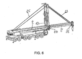
- Darstellungen, die den Abspanneinheits-Rüstvorgang eines Mobilkrans gemäß der vorliegenden Erfindung in verschiedenen Stadien aufzeigen; und
- Fig. 8
- eine Darstellung einer alternativen, erfindungsgemäßen Ausführungsform.
- Fig. 1:
- a guy unit as may be used in the present invention;
- Fig. 2:
- Details of the guy unit according to
Fig. 1 at the end where its support frame is for attachment to the boom; - 3 to 7:
- Illustrations showing the guy unit setup process of a mobile crane according to the present invention at various stages; and
- Fig. 8
- a representation of an alternative, inventive embodiment.
Das System gemäß der Erfindung wird beim hierin beschriebenen Ausführungsbeispiel anhand eines Mobil-Teleskopkrans realisiert, der beispielsweise in der
Ein Teleskopkran weist ein Fahrgestell 1, einen darauf drehbar angeordneten Oberwagen 2 und einen Ausleger 3 auf, der mindestens ein äußeres Auslegerteil 4 sowie ein oder mehrere innere Auslegerteile 5 umfasst und durch mindestens einen Wippzylinder um sein Drehachse wippbar ist. Im Kragenbereich 6 des äußeren Auslegerteiles 4 ist eine Abspannvorrichtung vorgesehen. Diese ist hydraulisch aufrichtbar und zu beiden Seiten hin seitlich schwenkbar und ihre variablen Abspannungen zum Festpunkt am Auslegerkopf 26 bzw. Festpunkt einer eventuell vorhandenen und festen Abspannungen zur Auslegerdrehachse dienen der Steifigkeitsvergrößerung um beide Achsen quer zur Auslegerlängsachse.A telescopic crane has a
Die komplette Abspanneinheit 9 wird separat zum Teleskopkran transportiert, und ist konstruktiv so ausgebildet, das Sie durch den Kran eigenständig rüstbar ist. Detaillierte Erläuterungen hierzu erfolgen anhand des in den Figuren gezeigten erfindungsgemäßen Systems, welches die folgenden Elemente umfasst:
Das Bezugszeichen 1 zeigt auf das Fahrgestell eines Mobil-Teleskopkrans mit Oberwagen 2 undAusleger 3. Das äußerstes Auslegerteil oder Auslegergrundteil 4 hat am äußerenEnde den Kragen 6, der zur Verbindung mit einem Halterahmen 10 dient.
- The
reference numeral 1 points to the chassis of a mobile telescopic crane withsuperstructure 2 andboom 3. The utmost boom part or boom base 4 has at the outer end of thecollar 6, which serves for connection to asupport frame 10.
Die Ziffer 8 bezeichnet in
Die Nummer 15 deutet jeweils auf einen oder mehrere Verriegelungszylinder je Auslegerseite zur Verbindung von Halterahmen 10 und Kragen 6, und mit 16 ist eine Windeneinheit zur Aufnahme der Abspannseile 23 und 24 angezeigt, wobei 23 eine variable Seilabspannung zum Auslegerkopf 26 ist.The
Weitere in den Zeichnungen dargestellte Elemente sind eine längenveränderliche Stütze 17, eine demontierbare Stütze 18, zwei demontierbare Druckstreben 19 und 20 zur Aussteifung, ein Seilgehänge 21 sowie Fixpunkte 22 auf dem Fahrgestell, die als (Teil der) Positionierungseinheit (oder auch Positionierungshilfe) dienen. Schließlich wird noch das Bezugszeichen 25 für eine feste Abspannung zwischen Abspanneinheit 9 und Auslegerfuß verwendet, 23 für die Befestigung der Seilabspannung am Auslegerkopf 26, 29 für ein Gitterteil mit Anschlagpunkt (Basis 27) und 30 für den Kranhaken (Hebemittel).Further elements shown in the drawings are a variable-
Das Rüsten der Abspanneinheit bzw. des Abspannbocks 9 wird nun in der unten beschriebenen Weise durchgeführt, wobei auf die
- Der Kran hat sich in
Figur 4 den Abspannbock 9 mittels Anschlagmittel (Hebemittel bzw. Haken 30) vom Transportfahrzeug bzw. Tieflader 8 (Fig. 3 ) gehoben, in Fahrzeuglängsachse geschwenkt, und mittels der Stützen 17 die auf dem Fahrgestell befindlichen Fixpunkte genau angefahren; damit ist der abgelegte Abspannbock 9 zur Koppelung der Bauteile 10 und 6 genau positioniert. Danach werden die Druckstützen 19 und 20 entfernt; somit ist der obere Bereich frei zum Einwippen des Auslegers. Hier kommt also die erfindungsgemäße Ausgestaltung des Halterahmens mit einem nach oben offenen Querschnitt zur Geltung. Wie dargestellt, kann die Abspanneinheitauf den Stützen
- The crane has moved in
FIG. 4 theguy trestle 9 by means of abutment means (lifting means or hooks 30) from the transport vehicle or low loader 8 (FIG.Fig. 3 ) lifted, pivoted in the vehicle longitudinal axis, and precisely approached by means of thesupports 17, the fixed points located on the chassis; Thus, the storedAbspannbock 9 is positioned to couple thecomponents supports
In
Die Stützen 18 werden dann entfernt, die Stützen 17 werden eingezogen.The supports 18 are then removed, the
Aus der
In der
Eine Darstellung einer alternativen Ausführungsform gemäß der vorliegenden Erfindung ist in der
- 11
- Fahrgestellchassis
- 22
- Oberwagensuperstructure
- 33
- Auslegerboom
- 44
- äußerstes Auslegerteilextreme boom part
- 55
- teleskopierbare Auslegerteiltelescopic boom section
- 66
- Kragen äußerstes AuslegerteilCollar extreme boom part
- 77
- Kopf des innersten AuslegerteilesHead of innermost boom part
- 88th
- Transportfahrzeugtransport vehicle
- 9, 9A9, 9A
- Abspannbock - TransporteinheitTensioning trestle - transport unit
- 1010
- Abspannbock - HalterahmenTie - down support frame
- 1111
- Abspannbock - AbspannstützeBracing trestle - bracing support
- 1212
- Abspannbock - AufrichtzylinderTensioning jack - erection cylinder
- 1313
- Abspannbock - SchwenkbockGuy trestle - swivel bracket
- 1414
- Abspannbock - SchwenkzylinderTensioning trestle - swivel cylinder
- 1515
- Abspannbock - VerriegelungszylinderTensioning trestle - locking cylinder
- 1616
- Abspannbock - WindeneinheitTensioning trestle - winch unit
- 17, 17A17, 17A
- Abspannbock - verlängerbare StützeTensioning trestle - extendable support
- 18, 18A18, 18A
- Abspannbock - demontierbare StützeTensioning trestle - removable support
- 1919
- Abspannbock - HilfsstützeTensioning trestle - auxiliary support
- 2020
- Abspannbock - demontierbare HilfsstützeTensioning trestle - removable auxiliary support
- 2121
- Anschlagmittelslings
- 2222
- Fixpunkte auf dem FahrgestellFixed points on the chassis
- 2323
- variable Abspannung Abspannbock - Auslegerkopfvariable bracing jack - boom head
- 2525
- feste Abspannung Abspannbock - Auslegerfußfixed bracing guy - boom foot
- 2626
- Festpunkt AuslegerkopfFixed point boom head
Claims (12)
- A telescopic crane bracing unit system, comprising:- a telescopic crane, in particular a mobile crane, comprising a bogie (1) and a superstructure (2) which is arranged on the bogie in such a way that it can be rotated and on which an erectable jib (3) is arranged which comprises an outer base part (4) of the jib and one or more telescopic parts (7) of the jib; and comprising- a bracing unit (9) which can be assembled on the jib (3) and comprises erectable bracing supports (11) and a holding frame (10) for fastening to the jib (3),- wherein the holding frame (10) connects the bracing supports (11) to form a structural unit, and characterised in that- the holding frame (10) exhibits a cross-section which opens upwards and, at its open position, allows the jib (3) to be inserted and/or engaged.
- The system according to Claim 1, characterised in that the holding frame (10) which opens upwards and is in particular open at the top on one side is configured to receive an assembling portion of the jib which can be a collar (6) of a part of the jib.
- The system according to Claim 1 or 2, characterised in that auxiliary supports (19, 20) which can be disassembled for the transport state of the bracing unit (9) are arranged between the free ends of the erecting supports and/or on the holding frame, specifically on its open cross-sectional portion.
- The system according to any one of Claims 1 to 3, characterised in that a jib bracing unit positioning unit (17, 18, 22) is provided, using which the jib (3) and the bracing unit (9) can be positioned in a defined way with respect to each other, such that an assembly engagement between the jib (3) and the holding frame (10) can be achieved by a jib movement.
- The system according to Claim 4, characterised in that the positioning unit (17, 18, 22) comprises positioning elements which are arranged at positions which establish a defined distance relationship between the jib (3) and the holding frame (10).
- The system according to Claim 4 or 5, characterised in that in order to position it in a defined way, the positioning unit (17, 18, 22) arranges the bracing unit (9) together with the holding frame (10) at a position at which the holding frame (10) is situated at a distance from the superstructure linking point of the jib (3) which corresponds to a bracing unit assembling length of the jib (3).
- The system according to any one of Claims 4 to 6, characterised in that cooperating parts of the positioning unit are arranged both on the telescopic crane, specifically on the bogie (1) and/or the superstructure (2), and on the bracing unit (9).
- The system according to any one of Claims 4 to 7, characterised in that the positioning unit comprises one or more of the following positioning elements:- abutments or markings, in particular markings which can be fixed;- positive-fit or force-fit defining means which prevent a movement in at least one plane;- positive-fit or force-fit defining means which prevent a movement in at least one jib bracing unit distance direction;- releasable locking devices, specifically force-releasable locking devices;- top-accessible and/or top-receptive, laterally definitive support receptacles, in particular in the form of hollows, cavities or attached receptacles which comprise a circumferential, specifically closed lateral lock, in particular an annular lateral lock (22);- positioning or setting supports (17, 18), which can be disassembled, on the bracing unit (9);- bracing unit lifting means, in particular cables and their contacts on the bracing unit (9) which are configured to move the bracing unit (9) together with the jib (3).
- The system according to any one of Claims 1 to 8, characterised in that the bracing supports (11) can be hydraulically pivoted laterally via the pivoting bracket (13).
- The system according to any one of Claims 1 to 9, characterised in that the bracing unit can be fastened, in the collar region of a part of the jib, in particular in the region of the collar (6) of the base part of the jib, to the latter.
- A method for assembling a bracing unit (9) on the jib (3) of a telescopic crane, in which:- the bracing unit is positioned, using the lifting means (30) provided on the jib (3), at a defined position at which an assembly engagement between the jib (3) and a holding frame (10) of the bracing unit (9) can be achieved by a jib movement;- the bracing unit (9) is released from the lifting means (30);- the jib (3) is moved to a bracing unit assembling length if this has not yet been reached after the bracing unit has been positioned; and- the jib is moved in order to establish the assembly engagement between the jib (3) and the holding frame (10), wherein it is inserted from above into a cross-section of the holding frame (10) which opens upwards.
- The use of any one of the systems of Claims 1 to 10 in assembling a bracing unit (9) on the jib (3) of a telescopic crane.
Applications Claiming Priority (1)
| Application Number | Priority Date | Filing Date | Title |
|---|---|---|---|
| DE102009020338A DE102009020338B4 (en) | 2009-05-07 | 2009-05-07 | Telescopic crane with self-assembling guying fixture and mounting method for a guying fixture |
Publications (2)
| Publication Number | Publication Date |
|---|---|
| EP2248754A1 EP2248754A1 (en) | 2010-11-10 |
| EP2248754B1 true EP2248754B1 (en) | 2014-06-11 |
Family
ID=42537900
Family Applications (1)
| Application Number | Title | Priority Date | Filing Date |
|---|---|---|---|
| EP10156455.7A Active EP2248754B1 (en) | 2009-05-07 | 2010-03-15 | Telescopic crane with self-fittable bracing device and fitting method for a bracing device |
Country Status (8)
| Country | Link |
|---|---|
| US (1) | US8689986B2 (en) |
| EP (1) | EP2248754B1 (en) |
| JP (1) | JP5391142B2 (en) |
| KR (1) | KR101123030B1 (en) |
| CN (1) | CN101880010B (en) |
| CA (1) | CA2697321C (en) |
| DE (1) | DE102009020338B4 (en) |
| ES (1) | ES2497510T3 (en) |
Cited By (7)
| Publication number | Priority date | Publication date | Assignee | Title |
|---|---|---|---|---|
| EP3587337A1 (en) * | 2018-06-28 | 2020-01-01 | Manitowoc Crane Group France SAS | Telescopic boom bracing device |
| DE102019120134B3 (en) * | 2019-07-25 | 2020-09-10 | Tadano Demag Gmbh | Vehicle crane and vehicle crane system as well as method for upgrading and dismantling a vehicle crane with a guy device |
| DE102019130241B3 (en) * | 2019-11-08 | 2021-02-04 | Tadano Demag Gmbh | Vehicle crane with a telescopic boom and vehicle crane system as well as a method for assembling a guy device on the telescopic boom of a vehicle crane |
| DE102020101101B3 (en) * | 2020-01-17 | 2021-05-20 | Tadano Demag Gmbh | Boom system for a vehicle crane with anchoring device as well as a method for upgrading and dismantling an anchoring device of a vehicle crane |
| DE102021111922B3 (en) | 2021-05-07 | 2022-11-03 | Liebherr-Werk Ehingen Gmbh | Guying system and method for a mobile crane telescopic boom |
| DE102024121051A1 (en) | 2023-07-26 | 2025-01-30 | Tadano Demag Gmbh | Mobile crane with a mounting frame and method for mounting a guying device on a telescopic boom |
| DE102023119815A1 (en) | 2023-07-26 | 2025-01-30 | Tadano Demag Gmbh | Mounting frame, mobile crane and method for mounting a guying device on a telescopic boom |
Families Citing this family (15)
| Publication number | Priority date | Publication date | Assignee | Title |
|---|---|---|---|---|
| US8678210B1 (en) * | 2010-11-17 | 2014-03-25 | Link-Belt Construction Equipment Co., L.P., Lllp | Telescoping boom assembly with base section having primary shell and secondary formed shell |
| AT12942U1 (en) * | 2011-11-08 | 2013-02-15 | Palfinger Ag | CRANE, ESPECIALLY LOADING CRANE FOR A VEHICLE |
| CN102730579B (en) * | 2012-07-02 | 2015-05-20 | 中联重科股份有限公司 | Support and automobile crane with same |
| DE102013011173B4 (en) * | 2013-07-04 | 2019-05-23 | Liebherr-Werk Ehingen Gmbh | Method for assembling a crane as well as articulation, telescopic boom and crane |
| DE102013011180B4 (en) * | 2013-07-04 | 2020-09-10 | Liebherr-Werk Ehingen Gmbh | Collar storage for a telescopic boom as well as telescopic boom and crane |
| CN104444850A (en) * | 2014-12-11 | 2015-03-25 | 徐州重型机械有限公司 | Wheeled crane and self-detaching and self-mounting method of supporting legs of wheeled crane |
| DE102017000389B4 (en) * | 2017-01-17 | 2018-11-15 | Liebherr-Werk Ehingen Gmbh | Crane boom, crane with such a crane boom and method for attaching a guy support to such a crane boom |
| CN107161886B (en) * | 2017-07-17 | 2019-10-25 | 徐州重型机械有限公司 | The auxiliary self installation method of crane, from method for dismounting and from disassembly system |
| CN107934806A (en) * | 2017-10-30 | 2018-04-20 | 北京紫竹慧建设服务股份有限公司 | A kind of movable arm type tower crane aids in luffing device |
| DE102018119316A1 (en) * | 2018-08-08 | 2020-02-13 | Terex Global Gmbh | Attachment part transport unit for a guy device, in particular a lateral superlift, of a mobile crane |
| DE102018119315A1 (en) * | 2018-08-08 | 2020-02-13 | Terex Global Gmbh | Attachment transport unit for transporting an attachment, in particular the main boom of a mobile crane |
| CN111824977B (en) * | 2020-03-03 | 2024-05-24 | 合肥恺文重工机械有限公司 | Full pneumatic crane |
| CN113086864A (en) * | 2021-04-19 | 2021-07-09 | 江苏和润智能装备有限公司 | Counterweight telescopic working arm |
| DE102021116532B3 (en) | 2021-06-25 | 2022-10-20 | Tadano Demag Gmbh | Mobile crane with a guying device on a telescopic boom |
| DE102021116531B3 (en) | 2021-06-25 | 2022-11-17 | Tadano Demag Gmbh | Mobile crane and method for mounting a guying device on a telescopic boom |
Family Cites Families (31)
| Publication number | Priority date | Publication date | Assignee | Title |
|---|---|---|---|---|
| US2936907A (en) * | 1957-11-01 | 1960-05-17 | D W Winkelman Company | Portable gantry crane |
| US2998856A (en) * | 1959-09-14 | 1961-09-05 | Mckiernan Terry Corp | Bottom brace and folding pile hammer leads construction |
| US4102094A (en) * | 1975-09-26 | 1978-07-25 | The Foundation Equipment Corporation | Bottom brace for crane |
| US4273244A (en) * | 1979-01-29 | 1981-06-16 | Fmc Corporation | Crane upperstructure self-transferring system |
| US4383792A (en) * | 1980-09-02 | 1983-05-17 | Clark G. Seabloom | Crane for detachable mounting on a truck bed |
| DE3139596A1 (en) * | 1981-10-05 | 1983-04-21 | Liebherr-Werk Ehingen Gmbh, 7930 Ehingen | HEAVY DUTY TELESCOPIC CRANE |
| US4434994A (en) * | 1982-04-28 | 1984-03-06 | Pepin Julien H | Boom axle |
| US4662527A (en) * | 1983-04-22 | 1987-05-05 | Fmc Corporation | Hydraulic circuit for self-undecking crane |
| US4700851A (en) * | 1985-04-18 | 1987-10-20 | Reeve Richard J | Lightweight, self-powered, transportable crane assembly |
| US5240129A (en) * | 1990-06-04 | 1993-08-31 | Link-Belt Construction Equip. Co. | Heavy duty crane with self-retracting/erecting live mast |
| US5427256A (en) * | 1991-09-20 | 1995-06-27 | The Manitowoc Company, Inc. | Crane upper works to lower works alignment system |
| US5484069A (en) * | 1991-09-20 | 1996-01-16 | The Manitowoc Company, Inc. | Process for self-disassembling a crawler crane |
| US5725112A (en) * | 1991-12-17 | 1998-03-10 | Thorby; Donald Frederick | Crane |
| CH686365A5 (en) * | 1992-10-06 | 1996-03-15 | Werner Hofliger | Mobile crane. |
| JP3131896B2 (en) * | 1995-07-20 | 2001-02-05 | 辰雄 小野 | Shoring |
| CN2249232Y (en) * | 1996-01-31 | 1997-03-12 | 徐州工程机械集团有限公司 | Size-changeable superlong auxiliary arm device for crane |
| US5690240A (en) * | 1996-07-31 | 1997-11-25 | Thiermann Industries, Inc. | Dolly with detachable boom |
| US6702132B1 (en) * | 1999-03-19 | 2004-03-09 | Link-Belt Construction Equipment Company, L.P., Lllp | Crane self-assembly system |
| US6695158B2 (en) * | 2002-02-04 | 2004-02-24 | Manitowoc Crane Companies, Inc. | Crane with self-raising mast |
| EP1342692B1 (en) * | 2002-03-04 | 2008-06-18 | Liebherr-Werk Ehingen GmbH | Mobile crane with telescopic boom and method for mounting and dismounting brace elements for telescopic boom |
| ATE353849T1 (en) * | 2002-06-05 | 2007-03-15 | Liebherr Werk Ehingen | TELESCOPIC BOOM OF A CRANE |
| EP1735233B1 (en) * | 2004-03-26 | 2010-09-01 | Terex Demag GmbH | Mobile crane system comprising a mobile crane and an auxiliary device for assembly of a bracing device |
| US7331748B2 (en) * | 2004-06-08 | 2008-02-19 | Morton Buildings | Assembly for mounting various work tools to a construction vehicle |
| DE202005005627U1 (en) * | 2005-04-08 | 2006-08-17 | Liebherr-Werk Ehingen Gmbh | Crane with anchoring device for moving loads has at least one anchoring support fixed to rocker cylinder |
| JP4880246B2 (en) * | 2005-04-26 | 2012-02-22 | 株式会社タダノ | Mobile crane |
| US20070059142A1 (en) * | 2005-08-30 | 2007-03-15 | Dambroseo Michael F | "Mdporta-lift" transportable, transformable, telescoping, leightweight, cantilevered trolley track, half ton capacity material conveying lift |
| FR2892405B1 (en) * | 2005-10-26 | 2007-12-07 | Potain Soc Par Actions Simplif | METHOD AND DEVICE FOR MOUNTING A CRANE WITH AN ADJUSTABLE ARROW |
| US7377398B2 (en) * | 2006-01-13 | 2008-05-27 | Frank Paul Lichinchi | Portable knockdown trolley hoist |
| US7874438B2 (en) * | 2007-08-16 | 2011-01-25 | Despres Jean | Boom assembly |
| DE102007056289B4 (en) * | 2007-10-29 | 2009-06-04 | Liebherr-Werk Ehingen Gmbh | Method for erecting a crane jib |
| US8192128B2 (en) * | 2009-05-20 | 2012-06-05 | T&T Engineering Services, Inc. | Alignment apparatus and method for a boom of a pipe handling system |
-
2009
- 2009-05-07 DE DE102009020338A patent/DE102009020338B4/en active Active
-
2010
- 2010-03-15 EP EP10156455.7A patent/EP2248754B1/en active Active
- 2010-03-15 ES ES10156455.7T patent/ES2497510T3/en active Active
- 2010-03-19 CA CA2697321A patent/CA2697321C/en not_active Expired - Fee Related
- 2010-04-09 KR KR1020100032607A patent/KR101123030B1/en not_active IP Right Cessation
- 2010-04-29 CN CN201010160545.0A patent/CN101880010B/en active Active
- 2010-05-06 US US12/775,161 patent/US8689986B2/en active Active
- 2010-05-07 JP JP2010106856A patent/JP5391142B2/en active Active
Cited By (11)
| Publication number | Priority date | Publication date | Assignee | Title |
|---|---|---|---|---|
| EP3587337A1 (en) * | 2018-06-28 | 2020-01-01 | Manitowoc Crane Group France SAS | Telescopic boom bracing device |
| DE102019120134B3 (en) * | 2019-07-25 | 2020-09-10 | Tadano Demag Gmbh | Vehicle crane and vehicle crane system as well as method for upgrading and dismantling a vehicle crane with a guy device |
| WO2021013843A1 (en) | 2019-07-25 | 2021-01-28 | Tadano Demag Gmbh | Mobile crane, mobile crane system and method for adding and removing guying equipment to and from a mobile crane |
| US12162731B2 (en) | 2019-07-25 | 2024-12-10 | Tadano Demag Gmbh | Mobile crane, mobile crane system and method for adding and removing guying equipment to and from a mobile crane |
| DE102019130241B3 (en) * | 2019-11-08 | 2021-02-04 | Tadano Demag Gmbh | Vehicle crane with a telescopic boom and vehicle crane system as well as a method for assembling a guy device on the telescopic boom of a vehicle crane |
| US11427446B2 (en) | 2019-11-08 | 2022-08-30 | Tadano Demag Gmbh | Vehicle crane having a telescoping jib and vehicle crane system and method for mounting a bracing apparatus on the telescoping jib of a vehicle crane |
| DE102020101101B3 (en) * | 2020-01-17 | 2021-05-20 | Tadano Demag Gmbh | Boom system for a vehicle crane with anchoring device as well as a method for upgrading and dismantling an anchoring device of a vehicle crane |
| US11753282B2 (en) | 2020-01-17 | 2023-09-12 | Tadano Demag Gmbh | Jib system for a vehicle crane comprising a bracing apparatus and method for rigging and de-rigging a bracing apparatus of a vehicle crane |
| DE102021111922B3 (en) | 2021-05-07 | 2022-11-03 | Liebherr-Werk Ehingen Gmbh | Guying system and method for a mobile crane telescopic boom |
| DE102024121051A1 (en) | 2023-07-26 | 2025-01-30 | Tadano Demag Gmbh | Mobile crane with a mounting frame and method for mounting a guying device on a telescopic boom |
| DE102023119815A1 (en) | 2023-07-26 | 2025-01-30 | Tadano Demag Gmbh | Mounting frame, mobile crane and method for mounting a guying device on a telescopic boom |
Also Published As
| Publication number | Publication date |
|---|---|
| EP2248754A1 (en) | 2010-11-10 |
| US8689986B2 (en) | 2014-04-08 |
| CA2697321A1 (en) | 2010-11-07 |
| KR20100121409A (en) | 2010-11-17 |
| JP2010260725A (en) | 2010-11-18 |
| US20100282700A1 (en) | 2010-11-11 |
| KR101123030B1 (en) | 2012-03-16 |
| DE102009020338B4 (en) | 2011-07-21 |
| DE102009020338A1 (en) | 2010-11-18 |
| ES2497510T3 (en) | 2014-09-23 |
| CN101880010B (en) | 2013-04-03 |
| JP5391142B2 (en) | 2014-01-15 |
| CA2697321C (en) | 2012-12-04 |
| CN101880010A (en) | 2010-11-10 |
Similar Documents
| Publication | Publication Date | Title |
|---|---|---|
| EP2248754B1 (en) | Telescopic crane with self-fittable bracing device and fitting method for a bracing device | |
| EP1900675B1 (en) | Crane truck | |
| EP2984253B1 (en) | Mobile concrete pump with distributing boom and support device | |
| EP1760031B1 (en) | Crane lower body optimised for transport | |
| DE102013009357A1 (en) | Modular mobile crane | |
| EP2707322A1 (en) | Rotating tower crane | |
| EP3587337B1 (en) | Telescopic boom bracing device | |
| DE202021106818U1 (en) | Mobile crane with a counterweight device | |
| DE202005015044U1 (en) | A vehicle crane system comprising a vehicle crane and an assembly aid for assembling a guying device | |
| DE102014012661B4 (en) | Method of operating a crane and crane | |
| EP4086218A1 (en) | Clamping system and method for a mobile crane telescopic boom | |
| DE102012023814B4 (en) | Folding tip for a mobile crane and method for pivoting the folding top | |
| EP2377804B1 (en) | Mobile crane, in particular mobile construction crane | |
| DE4303944C2 (en) | Lifting device, in particular for laying curbs, paving slabs and the like | |
| DE202013011183U1 (en) | Telescopic super lift mast | |
| DE202005005627U1 (en) | Crane with anchoring device for moving loads has at least one anchoring support fixed to rocker cylinder | |
| DE20203443U1 (en) | Telescopic jib has bracing supports pivotable around only one single respective pivot point inclined do that supports spread out in V-form during orientation into operating position | |
| DE202004013077U1 (en) | Vehicle crane for lifting objects has base arm, which is detachably connected to main arm whereby one or two tightening supports are arranged on base arm | |
| DE2931422C3 (en) | Top slewing tower crane | |
| DE102022128653B4 (en) | Mobile crane with lattice boom, lattice boom and method for assembling such a crane | |
| EP4083346B1 (en) | Supporting device for an automatic concrete pump | |
| DE102020119728B4 (en) | Crane boom transport frame | |
| DE102023109566A1 (en) | Mobile crane with counterweight device, counterweight device and method for assembling such a device | |
| EP1541520A1 (en) | Mobile crane | |
| DE102023119815A1 (en) | Mounting frame, mobile crane and method for mounting a guying device on a telescopic boom |
Legal Events
| Date | Code | Title | Description |
|---|---|---|---|
| PUAI | Public reference made under article 153(3) epc to a published international application that has entered the european phase |
Free format text: ORIGINAL CODE: 0009012 |
|
| AK | Designated contracting states |
Kind code of ref document: A1 Designated state(s): AT BE BG CH CY CZ DE DK EE ES FI FR GB GR HR HU IE IS IT LI LT LU LV MC MK MT NL NO PL PT RO SE SI SK SM TR |
|
| AX | Request for extension of the european patent |
Extension state: AL BA ME RS |
|
| 17P | Request for examination filed |
Effective date: 20110408 |
|
| GRAP | Despatch of communication of intention to grant a patent |
Free format text: ORIGINAL CODE: EPIDOSNIGR1 |
|
| INTG | Intention to grant announced |
Effective date: 20140217 |
|
| GRAS | Grant fee paid |
Free format text: ORIGINAL CODE: EPIDOSNIGR3 |
|
| GRAA | (expected) grant |
Free format text: ORIGINAL CODE: 0009210 |
|
| AK | Designated contracting states |
Kind code of ref document: B1 Designated state(s): AT BE BG CH CY CZ DE DK EE ES FI FR GB GR HR HU IE IS IT LI LT LU LV MC MK MT NL NO PL PT RO SE SI SK SM TR |
|
| REG | Reference to a national code |
Ref country code: GB Ref legal event code: FG4D Free format text: NOT ENGLISH |
|
| REG | Reference to a national code |
Ref country code: CH Ref legal event code: EP |
|
| REG | Reference to a national code |
Ref country code: IE Ref legal event code: FG4D Free format text: LANGUAGE OF EP DOCUMENT: GERMAN |
|
| REG | Reference to a national code |
Ref country code: AT Ref legal event code: REF Ref document number: 672156 Country of ref document: AT Kind code of ref document: T Effective date: 20140715 |
|
| REG | Reference to a national code |
Ref country code: DE Ref legal event code: R096 Ref document number: 502010007166 Country of ref document: DE Effective date: 20140724 |
|
| REG | Reference to a national code |
Ref country code: ES Ref legal event code: FG2A Ref document number: 2497510 Country of ref document: ES Kind code of ref document: T3 Effective date: 20140923 |
|
| PG25 | Lapsed in a contracting state [announced via postgrant information from national office to epo] |
Ref country code: LT Free format text: LAPSE BECAUSE OF FAILURE TO SUBMIT A TRANSLATION OF THE DESCRIPTION OR TO PAY THE FEE WITHIN THE PRESCRIBED TIME-LIMIT Effective date: 20140611 Ref country code: NO Free format text: LAPSE BECAUSE OF FAILURE TO SUBMIT A TRANSLATION OF THE DESCRIPTION OR TO PAY THE FEE WITHIN THE PRESCRIBED TIME-LIMIT Effective date: 20140911 Ref country code: GR Free format text: LAPSE BECAUSE OF FAILURE TO SUBMIT A TRANSLATION OF THE DESCRIPTION OR TO PAY THE FEE WITHIN THE PRESCRIBED TIME-LIMIT Effective date: 20140912 Ref country code: FI Free format text: LAPSE BECAUSE OF FAILURE TO SUBMIT A TRANSLATION OF THE DESCRIPTION OR TO PAY THE FEE WITHIN THE PRESCRIBED TIME-LIMIT Effective date: 20140611 |
|
| REG | Reference to a national code |
Ref country code: NL Ref legal event code: VDEP Effective date: 20140611 |
|
| REG | Reference to a national code |
Ref country code: LT Ref legal event code: MG4D |
|
| PG25 | Lapsed in a contracting state [announced via postgrant information from national office to epo] |
Ref country code: HR Free format text: LAPSE BECAUSE OF FAILURE TO SUBMIT A TRANSLATION OF THE DESCRIPTION OR TO PAY THE FEE WITHIN THE PRESCRIBED TIME-LIMIT Effective date: 20140611 Ref country code: SE Free format text: LAPSE BECAUSE OF FAILURE TO SUBMIT A TRANSLATION OF THE DESCRIPTION OR TO PAY THE FEE WITHIN THE PRESCRIBED TIME-LIMIT Effective date: 20140611 Ref country code: LV Free format text: LAPSE BECAUSE OF FAILURE TO SUBMIT A TRANSLATION OF THE DESCRIPTION OR TO PAY THE FEE WITHIN THE PRESCRIBED TIME-LIMIT Effective date: 20140611 |
|
| PG25 | Lapsed in a contracting state [announced via postgrant information from national office to epo] |
Ref country code: RO Free format text: LAPSE BECAUSE OF FAILURE TO SUBMIT A TRANSLATION OF THE DESCRIPTION OR TO PAY THE FEE WITHIN THE PRESCRIBED TIME-LIMIT Effective date: 20140611 Ref country code: EE Free format text: LAPSE BECAUSE OF FAILURE TO SUBMIT A TRANSLATION OF THE DESCRIPTION OR TO PAY THE FEE WITHIN THE PRESCRIBED TIME-LIMIT Effective date: 20140611 Ref country code: SK Free format text: LAPSE BECAUSE OF FAILURE TO SUBMIT A TRANSLATION OF THE DESCRIPTION OR TO PAY THE FEE WITHIN THE PRESCRIBED TIME-LIMIT Effective date: 20140611 Ref country code: CZ Free format text: LAPSE BECAUSE OF FAILURE TO SUBMIT A TRANSLATION OF THE DESCRIPTION OR TO PAY THE FEE WITHIN THE PRESCRIBED TIME-LIMIT Effective date: 20140611 Ref country code: PT Free format text: LAPSE BECAUSE OF FAILURE TO SUBMIT A TRANSLATION OF THE DESCRIPTION OR TO PAY THE FEE WITHIN THE PRESCRIBED TIME-LIMIT Effective date: 20141013 |
|
| PG25 | Lapsed in a contracting state [announced via postgrant information from national office to epo] |
Ref country code: NL Free format text: LAPSE BECAUSE OF FAILURE TO SUBMIT A TRANSLATION OF THE DESCRIPTION OR TO PAY THE FEE WITHIN THE PRESCRIBED TIME-LIMIT Effective date: 20140611 Ref country code: IS Free format text: LAPSE BECAUSE OF FAILURE TO SUBMIT A TRANSLATION OF THE DESCRIPTION OR TO PAY THE FEE WITHIN THE PRESCRIBED TIME-LIMIT Effective date: 20141011 Ref country code: PL Free format text: LAPSE BECAUSE OF FAILURE TO SUBMIT A TRANSLATION OF THE DESCRIPTION OR TO PAY THE FEE WITHIN THE PRESCRIBED TIME-LIMIT Effective date: 20140611 |
|
| REG | Reference to a national code |
Ref country code: DE Ref legal event code: R097 Ref document number: 502010007166 Country of ref document: DE |
|
| REG | Reference to a national code |
Ref country code: DE Ref legal event code: R082 Ref document number: 502010007166 Country of ref document: DE Representative=s name: SCHWABE SANDMAIR MARX, DE |
|
| RAP2 | Party data changed (patent owner data changed or rights of a patent transferred) |
Owner name: MANITOWOC CRANE GROUP FRANCE SAS |
|
| PLBE | No opposition filed within time limit |
Free format text: ORIGINAL CODE: 0009261 |
|
| STAA | Information on the status of an ep patent application or granted ep patent |
Free format text: STATUS: NO OPPOSITION FILED WITHIN TIME LIMIT |
|
| REG | Reference to a national code |
Ref country code: DE Ref legal event code: R082 Ref document number: 502010007166 Country of ref document: DE Representative=s name: SCHWABE SANDMAIR MARX PATENTANWAELTE RECHTSANW, DE Effective date: 20150317 Ref country code: DE Ref legal event code: R081 Ref document number: 502010007166 Country of ref document: DE Owner name: MANITOWOC CRANE GROUP FRANCE SAS, FR Free format text: FORMER OWNER: MANITOWOC CRANE GROUP FRANCE SAS, ECULLY, FR Effective date: 20150317 Ref country code: DE Ref legal event code: R082 Ref document number: 502010007166 Country of ref document: DE Representative=s name: SCHWABE SANDMAIR MARX, DE Effective date: 20150317 |
|
| PG25 | Lapsed in a contracting state [announced via postgrant information from national office to epo] |
Ref country code: DK Free format text: LAPSE BECAUSE OF FAILURE TO SUBMIT A TRANSLATION OF THE DESCRIPTION OR TO PAY THE FEE WITHIN THE PRESCRIBED TIME-LIMIT Effective date: 20140611 |
|
| 26N | No opposition filed |
Effective date: 20150312 |
|
| REG | Reference to a national code |
Ref country code: DE Ref legal event code: R097 Ref document number: 502010007166 Country of ref document: DE Effective date: 20150312 |
|
| PG25 | Lapsed in a contracting state [announced via postgrant information from national office to epo] |
Ref country code: SI Free format text: LAPSE BECAUSE OF FAILURE TO SUBMIT A TRANSLATION OF THE DESCRIPTION OR TO PAY THE FEE WITHIN THE PRESCRIBED TIME-LIMIT Effective date: 20140611 |
|
| PG25 | Lapsed in a contracting state [announced via postgrant information from national office to epo] |
Ref country code: LU Free format text: LAPSE BECAUSE OF FAILURE TO SUBMIT A TRANSLATION OF THE DESCRIPTION OR TO PAY THE FEE WITHIN THE PRESCRIBED TIME-LIMIT Effective date: 20150315 Ref country code: MC Free format text: LAPSE BECAUSE OF FAILURE TO SUBMIT A TRANSLATION OF THE DESCRIPTION OR TO PAY THE FEE WITHIN THE PRESCRIBED TIME-LIMIT Effective date: 20140611 |
|
| REG | Reference to a national code |
Ref country code: CH Ref legal event code: PL |
|
| GBPC | Gb: european patent ceased through non-payment of renewal fee |
Effective date: 20150315 |
|
| REG | Reference to a national code |
Ref country code: IE Ref legal event code: MM4A |
|
| PG25 | Lapsed in a contracting state [announced via postgrant information from national office to epo] |
Ref country code: LI Free format text: LAPSE BECAUSE OF NON-PAYMENT OF DUE FEES Effective date: 20150331 Ref country code: GB Free format text: LAPSE BECAUSE OF NON-PAYMENT OF DUE FEES Effective date: 20150315 Ref country code: IE Free format text: LAPSE BECAUSE OF NON-PAYMENT OF DUE FEES Effective date: 20150315 Ref country code: CH Free format text: LAPSE BECAUSE OF NON-PAYMENT OF DUE FEES Effective date: 20150331 |
|
| REG | Reference to a national code |
Ref country code: FR Ref legal event code: PLFP Year of fee payment: 7 |
|
| REG | Reference to a national code |
Ref country code: AT Ref legal event code: MM01 Ref document number: 672156 Country of ref document: AT Kind code of ref document: T Effective date: 20150315 |
|
| PG25 | Lapsed in a contracting state [announced via postgrant information from national office to epo] |
Ref country code: AT Free format text: LAPSE BECAUSE OF NON-PAYMENT OF DUE FEES Effective date: 20150315 |
|
| PG25 | Lapsed in a contracting state [announced via postgrant information from national office to epo] |
Ref country code: MT Free format text: LAPSE BECAUSE OF FAILURE TO SUBMIT A TRANSLATION OF THE DESCRIPTION OR TO PAY THE FEE WITHIN THE PRESCRIBED TIME-LIMIT Effective date: 20140611 |
|
| REG | Reference to a national code |
Ref country code: FR Ref legal event code: PLFP Year of fee payment: 8 |
|
| PG25 | Lapsed in a contracting state [announced via postgrant information from national office to epo] |
Ref country code: SM Free format text: LAPSE BECAUSE OF FAILURE TO SUBMIT A TRANSLATION OF THE DESCRIPTION OR TO PAY THE FEE WITHIN THE PRESCRIBED TIME-LIMIT Effective date: 20140611 Ref country code: BG Free format text: LAPSE BECAUSE OF FAILURE TO SUBMIT A TRANSLATION OF THE DESCRIPTION OR TO PAY THE FEE WITHIN THE PRESCRIBED TIME-LIMIT Effective date: 20140611 Ref country code: HU Free format text: LAPSE BECAUSE OF FAILURE TO SUBMIT A TRANSLATION OF THE DESCRIPTION OR TO PAY THE FEE WITHIN THE PRESCRIBED TIME-LIMIT; INVALID AB INITIO Effective date: 20100315 |
|
| PG25 | Lapsed in a contracting state [announced via postgrant information from national office to epo] |
Ref country code: CY Free format text: LAPSE BECAUSE OF FAILURE TO SUBMIT A TRANSLATION OF THE DESCRIPTION OR TO PAY THE FEE WITHIN THE PRESCRIBED TIME-LIMIT Effective date: 20140611 |
|
| PG25 | Lapsed in a contracting state [announced via postgrant information from national office to epo] |
Ref country code: BE Free format text: LAPSE BECAUSE OF NON-PAYMENT OF DUE FEES Effective date: 20150331 |
|
| PG25 | Lapsed in a contracting state [announced via postgrant information from national office to epo] |
Ref country code: TR Free format text: LAPSE BECAUSE OF FAILURE TO SUBMIT A TRANSLATION OF THE DESCRIPTION OR TO PAY THE FEE WITHIN THE PRESCRIBED TIME-LIMIT Effective date: 20140611 |
|
| REG | Reference to a national code |
Ref country code: FR Ref legal event code: PLFP Year of fee payment: 9 |
|
| PG25 | Lapsed in a contracting state [announced via postgrant information from national office to epo] |
Ref country code: MK Free format text: LAPSE BECAUSE OF FAILURE TO SUBMIT A TRANSLATION OF THE DESCRIPTION OR TO PAY THE FEE WITHIN THE PRESCRIBED TIME-LIMIT Effective date: 20140611 |
|
| PGFP | Annual fee paid to national office [announced via postgrant information from national office to epo] |
Ref country code: ES Payment date: 20200522 Year of fee payment: 11 |
|
| REG | Reference to a national code |
Ref country code: ES Ref legal event code: FD2A Effective date: 20220523 |
|
| PG25 | Lapsed in a contracting state [announced via postgrant information from national office to epo] |
Ref country code: ES Free format text: LAPSE BECAUSE OF NON-PAYMENT OF DUE FEES Effective date: 20210316 |
|
| P01 | Opt-out of the competence of the unified patent court (upc) registered |
Effective date: 20230515 |
|
| PGFP | Annual fee paid to national office [announced via postgrant information from national office to epo] |
Ref country code: DE Payment date: 20240320 Year of fee payment: 15 |
|
| PGFP | Annual fee paid to national office [announced via postgrant information from national office to epo] |
Ref country code: IT Payment date: 20240329 Year of fee payment: 15 Ref country code: FR Payment date: 20240322 Year of fee payment: 15 |