EP2984253B1 - Mobile concrete pump with distributing boom and support device - Google Patents
Mobile concrete pump with distributing boom and support device Download PDFInfo
- Publication number
- EP2984253B1 EP2984253B1 EP14707133.6A EP14707133A EP2984253B1 EP 2984253 B1 EP2984253 B1 EP 2984253B1 EP 14707133 A EP14707133 A EP 14707133A EP 2984253 B1 EP2984253 B1 EP 2984253B1
- Authority
- EP
- European Patent Office
- Prior art keywords
- concrete pump
- support
- support structure
- shell
- bearing
- Prior art date
- Legal status (The legal status is an assumption and is not a legal conclusion. Google has not performed a legal analysis and makes no representation as to the accuracy of the status listed.)
- Active
Links
- 230000000630 rising effect Effects 0.000 claims description 3
- NJPPVKZQTLUDBO-UHFFFAOYSA-N novaluron Chemical compound C1=C(Cl)C(OC(F)(F)C(OC(F)(F)F)F)=CC=C1NC(=O)NC(=O)C1=C(F)C=CC=C1F NJPPVKZQTLUDBO-UHFFFAOYSA-N 0.000 claims 4
- 238000009434 installation Methods 0.000 description 3
- 239000000463 material Substances 0.000 description 3
- 238000010276 construction Methods 0.000 description 2
- 230000009471 action Effects 0.000 description 1
- 230000008859 change Effects 0.000 description 1
- 230000007423 decrease Effects 0.000 description 1
- 230000001419 dependent effect Effects 0.000 description 1
- 230000007246 mechanism Effects 0.000 description 1
- 230000004048 modification Effects 0.000 description 1
- 238000012986 modification Methods 0.000 description 1
- 230000009467 reduction Effects 0.000 description 1
- 239000000758 substrate Substances 0.000 description 1
Images

Classifications
-
- E—FIXED CONSTRUCTIONS
- E04—BUILDING
- E04G—SCAFFOLDING; FORMS; SHUTTERING; BUILDING IMPLEMENTS OR AIDS, OR THEIR USE; HANDLING BUILDING MATERIALS ON THE SITE; REPAIRING, BREAKING-UP OR OTHER WORK ON EXISTING BUILDINGS
- E04G21/00—Preparing, conveying, or working-up building materials or building elements in situ; Other devices or measures for constructional work
- E04G21/02—Conveying or working-up concrete or similar masses able to be heaped or cast
- E04G21/04—Devices for both conveying and distributing
- E04G21/0418—Devices for both conveying and distributing with distribution hose
- E04G21/0445—Devices for both conveying and distributing with distribution hose with booms
-
- B—PERFORMING OPERATIONS; TRANSPORTING
- B60—VEHICLES IN GENERAL
- B60S—SERVICING, CLEANING, REPAIRING, SUPPORTING, LIFTING, OR MANOEUVRING OF VEHICLES, NOT OTHERWISE PROVIDED FOR
- B60S9/00—Ground-engaging vehicle fittings for supporting, lifting, or manoeuvring the vehicle, wholly or in part, e.g. built-in jacks
- B60S9/02—Ground-engaging vehicle fittings for supporting, lifting, or manoeuvring the vehicle, wholly or in part, e.g. built-in jacks for only lifting or supporting
-
- B—PERFORMING OPERATIONS; TRANSPORTING
- B66—HOISTING; LIFTING; HAULING
- B66C—CRANES; LOAD-ENGAGING ELEMENTS OR DEVICES FOR CRANES, CAPSTANS, WINCHES, OR TACKLES
- B66C23/00—Cranes comprising essentially a beam, boom, or triangular structure acting as a cantilever and mounted for translatory of swinging movements in vertical or horizontal planes or a combination of such movements, e.g. jib-cranes, derricks, tower cranes
- B66C23/62—Constructional features or details
- B66C23/72—Counterweights or supports for balancing lifting couples
- B66C23/78—Supports, e.g. outriggers, for mobile cranes
- B66C23/80—Supports, e.g. outriggers, for mobile cranes hydraulically actuated
-
- E—FIXED CONSTRUCTIONS
- E04—BUILDING
- E04G—SCAFFOLDING; FORMS; SHUTTERING; BUILDING IMPLEMENTS OR AIDS, OR THEIR USE; HANDLING BUILDING MATERIALS ON THE SITE; REPAIRING, BREAKING-UP OR OTHER WORK ON EXISTING BUILDINGS
- E04G21/00—Preparing, conveying, or working-up building materials or building elements in situ; Other devices or measures for constructional work
- E04G21/02—Conveying or working-up concrete or similar masses able to be heaped or cast
- E04G21/04—Devices for both conveying and distributing
- E04G21/0418—Devices for both conveying and distributing with distribution hose
- E04G21/0436—Devices for both conveying and distributing with distribution hose on a mobile support, e.g. truck
Definitions
- the boiler wall forms a truncated cone or a truncated pyramid with a downwardly open, obliquely rising in the direction of travel of the concrete pump blunt surface.
- the boiler can be supported with its sloping butt surface on a sloping in the direction of travel support frame of the support structure.
- the invention relates to a mobile concrete pump according to claim 1.
- the boiler 42 engages with a in cross section from top to bottom tapered or truncated pyramid vessel wall 56 in the support structure 17 and is rigidly inserted into this, preferably welded.
Landscapes
- Engineering & Computer Science (AREA)
- Architecture (AREA)
- Mechanical Engineering (AREA)
- Civil Engineering (AREA)
- Structural Engineering (AREA)
- On-Site Construction Work That Accompanies The Preparation And Application Of Concrete (AREA)
- Vehicle Cleaning, Maintenance, Repair, Refitting, And Outriggers (AREA)
- Health & Medical Sciences (AREA)
- Public Health (AREA)
- Transportation (AREA)
Description
Die Erfindung bezieht sich auf eine fahrbare Betonpumpe gemäß dem Oberbegriff des Anspruchs 1. Autobetonpumpen dieser Art sind bekannt (
Ausgehend hiervon liegt der Erfindung die Aufgabe zugrunde, die bekannte fahrbare Betonpumpe im Bereich ihrer Tragstruktur leichter, platzsparender und dennoch belastungsgerecht zu gestalten.Proceeding from this, the present invention seeks to make the known mobile concrete pump in the region of its support structure easier, space-saving and yet load-appropriate.
Zur Lösung dieser Aufgabe werden die im Patentanspruch 1 angegebenen Merkmale vorgeschlagen. Vorteilhafte Ausgestaltungen und Weiterbildungen der Erfindung ergeben sich aus den abhängigen Ansprüchen.To solve this problem the features specified in
Die erfindungsgemäße Lösung geht von dem Gedanken aus, dass sich eine leichte und dennoch belastungsgerechte Konstruktion ergibt, wenn sich der Kessel von oben nach unten im Querschnitt verjüngt. Dementsprechend wird gemäß der Erfindung vorgeschlagen, dass der Kessel mit seiner im Querschnitt von oben nach unten kegel- oder pyramidenstumpfartig verjüngenden Kesselwand in die Tragstruktur eingreift und in diese starr eingefügt ist.The solution according to the invention is based on the idea that results in a lightweight, yet load-friendly construction, when the boiler tapers from top to bottom in cross section. Accordingly, it is proposed according to the invention that the boiler engages with its in cross section from top to bottom cone or truncated pyramidal tapered boiler wall into the support structure and is rigidly inserted into this.
Die erfindungsgemäße Konstruktion spart unnötigen Materialeinsatz und senkt damit das Bauteilgewicht und damit auch das Maschinengewicht. Die sich von oben nach unten verjüngende Form schafft Raum zwischen der Abstützkonstruktion und dem Mastbock, in welchem die notwendigen Installationen insbesondere bei Tragstrukturen mit vier Schwenkbeinen raumsparend untergebracht werden können. Vorteilhafterweise lassen sich im gewonnenen Bauraum Teleskopzylinder für Teleskopschwenkbeine unterbringen, die bislang aufwändig, teuer und nur schwer zugänglich im Inneren der Teleskopbeine untergebracht werden mussten. Dieser Raumgewinn ist vor allem bei Großmaschinen von Bedeutung.The construction according to the invention saves unnecessary use of material and thus reduces the component weight and thus also the weight of the machine. The tapered shape from top to bottom creates space between the support structure and the mast block, in which the necessary installations can be accommodated in a space-saving manner, in particular in support structures with four pivot legs. Advantageously, can be accommodated in the space obtained telescopic cylinder for telescopic swivel legs, which previously had to be laboriously, expensive and difficult to access housed inside the telescopic legs. This space gain is especially important for large machines.
Eine bevorzugte Ausgestaltung der Erfindung sieht vor, dass der Kessel eine vertikale Durchgangsöffnung für den Durchtritt einer Betonförderleitung aufweist.A preferred embodiment of the invention provides that the boiler has a vertical passage opening for the passage of a concrete delivery line.
Eine weitere vorteilhafte Ausgestaltung der Erfindung sieht vor, dass am Kessel zur Tragstruktur gehörende Lagerarme angeschweißt sind, die im Abstand von der Kesselwand angeordnete Lageraugen aufweisen, an denen jeweils eines der Stützbeine um eine vertikale Achse schwenkbar gelagert ist.A further advantageous embodiment of the invention provides that on the boiler belonging to the support structure bearing arms are welded in the Have spaced from the boiler wall arranged bearing eyes, on each of which one of the support legs is pivotally mounted about a vertical axis.
Eine weitere Verringerung des Materialeinsatzes kann dadurch erzielt werden, dass die Kesselwand einen Kegelstumpf oder einen Pyramidenstumpf mit einer nach unten hin offenen, in Fahrtrichtung der Betonpumpe schräg ansteigenden Stumpffläche bildet. Der Kessel kann dabei mit seiner schrägen Stumpffläche auf einem in Fahrtrichtung schräg ansteigenden Stützrahmen der Tragstruktur abgestützt werden.A further reduction in the use of materials can be achieved in that the boiler wall forms a truncated cone or a truncated pyramid with a downwardly open, obliquely rising in the direction of travel of the concrete pump blunt surface. The boiler can be supported with its sloping butt surface on a sloping in the direction of travel support frame of the support structure.
Im Folgenden wird die Erfindung anhand eines in der Zeichnung in schematischer Weise dargestellten Ausführungsbeispiels näher erläutert. Es zeigen
- Fig. 1a
- und b eine Seitenansicht und eine Draufsicht einer Autobetonpumpe mit einem Verteilermast und einer Ausstellvorrichtung;
- Fig. 2
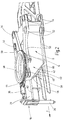
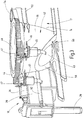
- und 3 je eine schaubildliche Darstellung der Tragstruktur der Autobetonpumpe nach
Fig. 1a und b mit einem Stützbein der Abstützvorrichtung und dem im Mastbock der Tragstruktur angeordneten Kessel.
- Fig. 1a
- and b is a side view and a plan view of a truck-mounted concrete pump with a placing boom and a raising device;
- Fig. 2
- and 3 each show a perspective view of the support structure of the truck-mounted concrete pump
Fig. 1a and b with a support leg of the support device and arranged in the mast of the support structure boiler.
Die in
Zentraler Bestandteil des Mastbocks 14 ist der Kessel 42, der die Schnittstelle zwischen dem Verteilermast 15 und der Abstützvorrichtung 18 bildet. Der Drehkopf 19 des Verteilermasts ist von oben her auf den Kessel 42 aufgesetzt und dort um eine vertikale Achse drehbar gelagert. Der Antrieb erfolgt über einen am Drehkopf 19 starr angeordneten und über ein Wälzlager am Kessel drehbar gelagerten Zahnring 44 mit Hilfe zweier hydraulischer oder elektrischer Antriebsmotoren 45, die mit einem Antriebsritzel 57 in den Zahnring 44 eingreifen. Die Antriebsmotoren 45 sind an kesselfesten Laschen 46 des Mastbocks angeordnet. Der Kessel weist eine vertikale Durchgangsöffnung 43 für den Durchtritt einer nicht dargestellten Betonförderleitung auf. Da der Kessel ein Vertikallager für den Verteilermast 15 bildet, nimmt er die Belastung über seine Höhe auf. Die Belastung ist am oberen Ende nahe des Drehlagers 48 maximal und nimmt nach unten hin ab.The central component of the
Die Form des Kessels 42 ist dem Belastungsverlauf dadurch angepasst, dass sein Querschnitt sich von oben nach unten konisch verjüngt. Diese Konstruktion spart unnötigen Materialeinsatz und senkt das Bauteilgewicht und damit auch das Maschinengewicht. Die konische Form schafft außerdem Raum zwischen den Stützbeinen 20 und dem Mastbock 14 zur Unterbringung der notwendigen Installationen. Insbesondere lassen sich im gewonnenen Bauraum die Teleskopzylinder 62 für die teleskopierbaren Stützbeine 20 unterbringen, die bisher nur schwer zugänglich im Inneren der Teleskopbeine untergebracht werden konnten.The shape of the
Wie aus
Wie aus
Zusammenfassend ist folgendes festzuhalten: Die Erfindung bezieht sich auf eine fahrbare Betonpumpe gemäß Anspruch 1. Der Kessel 42 greift mit einer sich im Querschnitt von oben nach unten kegel- oder pyramidenstumpfartig verjüngenden Kesselwand 56 in die Tragstruktur 17 ein und ist in diese starr eingefügt, vorzugsweise eingeschweißt.In summary, the following should be noted: The invention relates to a mobile concrete pump according to
- 1010
- Fahrgestellchassis
- 1111
- VorderachseFront
- 1212
- Hinterachserear axle
- 1313
- Führerhauscabin
- 1414
- Mastbockboom base
- 1515
- BetonverteilermastConcrete placing boom
- 1616
- Pumpanordnungpump assembly
- 1717
- Tragstruktursupporting structure
- 1818
- AbstützvorrichtungSupport device
- 1919
- Drehkopfturret
- 2020
- vordere Stützbeinefront support legs
- 22,22'22.22 '
- rückwärtige Stützbeinerear support legs
- 2424
- Fahrzeuglängsachsevehicle longitudinal axis
- 26,2826.28
- Fußteilefootboards
- 3030
- Untergrundunderground
- 32,3432.34
- vertikale Schwenkachsenvertical swivel axes
- 3636
- AusstellzylinderAusstellzylinder
- 3838
- Auslegerkastenboom box
- 4040
- Teleskopteiltelescopic part
- 4242
- Kesselboiler
- 4343
- DurchgangsöffnungThrough opening
- 4444
- ZahringZahring
- 4545
- Antriebsmotordrive motor
- 4646
- Laschentabs
- 4747
- Antriebsritzelpinion
- 4848
- Drehlagerpivot bearing
- 5050
- Lagerarmebearing arms
- 52,5452.54
- Lageraugenbearing eyes
- 5656
- Kesselwandboiler wall
- 5858
- Stumpfflächeconical surface
- 6060
- Stützrahmensupport frame
- 6262
- Teleskopzylindertelescopic cylinders
- FF
- Fahrtrichtungdirection of travel
Claims (6)
- A mobile concrete pump with a support structure (17) being placed on a vehicle frame (10) of a truck chassis and comprising functional units which form a support device (18) and a distributing boom (15), wherein the functional unit which forms the distributing boom (15) has a rotary head (19) mounted on a boom pedestal (14) in a rotatable manner about a vertical axis, said boom pedestal being secured to the support structure, and the boom pedestal (14) comprises a shell (42) which engages in the support structure (17) and is provided as a rotary bearing (48) for the rotary head (19), and wherein the functional units forming the support device (18) have a respective support leg (20, 22, 22') mounted in a bearing (52, 54) in a pivotable and/or telescopable manner, said bearing being secured to the support structure, characterized in that the shell (42), with a shell wall (56) which tapers in cross section from top to bottom in the shape of a truncated cone or truncated pyramid, engages in the support structure (17) and is rigidly inserted therein.
- The concrete pump as claimed in claim 1, characterized in that the shell (42) has a vertical through-opening (43) for the passage of a concrete conveying line.
- The concrete pump as claimed in claim 1 or 2, characterized in that bearing arms (50) forming part of the support structure (17) are welded onto the shell (42), said bearing arms having bearing eyes (52, 54) arranged spaced apart from the shell wall (56), in each case one of the support legs (20, 22, 22') being pivotably mounted thereon about a vertical axis.
- The concrete pump as claimed in one of claims 1 to 3, characterized in that the shell wall (56) forms a truncated cone or a truncated pyramid with an abutment surface (58) which is open downwardly and rises obliquely in the direction of travel (F) of the concrete pump.
- The concrete pump as claimed in claim 4, characterized in that the shell (42) is supported by its oblique abutment surface (58) on a support frame (60) of the support structure (17) rising obliquely in the direction of travel.
- The concrete pump as claimed in one of claims 1 to 5, characterized in that the front support legs (20) are made up of a plurality of telescopic members (40) which are able to be telescoped by means of a telescopic cylinder (62) which is able to be actuated hydraulically and which is arranged on the side facing the conical shell wall (56) outside the support legs (20).
Applications Claiming Priority (2)
| Application Number | Priority Date | Filing Date | Title |
|---|---|---|---|
| DE102013206366.0A DE102013206366A1 (en) | 2013-04-11 | 2013-04-11 | Mobile concrete pump with distribution boom and outriggers |
| PCT/EP2014/053777 WO2014166670A1 (en) | 2013-04-11 | 2014-02-27 | Mobile concrete pump with distributing boom and support device |
Publications (2)
| Publication Number | Publication Date |
|---|---|
| EP2984253A1 EP2984253A1 (en) | 2016-02-17 |
| EP2984253B1 true EP2984253B1 (en) | 2018-05-30 |
Family
ID=50189680
Family Applications (1)
| Application Number | Title | Priority Date | Filing Date |
|---|---|---|---|
| EP14707133.6A Active EP2984253B1 (en) | 2013-04-11 | 2014-02-27 | Mobile concrete pump with distributing boom and support device |
Country Status (8)
| Country | Link |
|---|---|
| US (1) | US9410334B2 (en) |
| EP (1) | EP2984253B1 (en) |
| JP (1) | JP6311005B2 (en) |
| KR (1) | KR20150142698A (en) |
| CN (1) | CN105392945B (en) |
| BR (1) | BR112015025506B1 (en) |
| DE (1) | DE102013206366A1 (en) |
| WO (1) | WO2014166670A1 (en) |
Families Citing this family (19)
| Publication number | Priority date | Publication date | Assignee | Title |
|---|---|---|---|---|
| DE102013206366A1 (en) * | 2013-04-11 | 2014-10-16 | Putzmeister Engineering Gmbh | Mobile concrete pump with distribution boom and outriggers |
| DE102013209878A1 (en) * | 2013-05-28 | 2014-12-04 | Putzmeister Engineering Gmbh | Implement with arranged on a turret work boom |
| DE102014200396A1 (en) * | 2014-01-13 | 2015-07-30 | Putzmeister Engineering Gmbh | Truck-mounted concrete pump and protection circuit for it |
| CN104442522B (en) * | 2014-12-29 | 2016-10-12 | 徐州海伦哲专用车辆股份有限公司 | A kind of Multifunctional strong-light mobilite |
| DE102015226314A1 (en) * | 2015-12-21 | 2017-06-22 | Terex Global Gmbh | Modular crane, transport unit for a modular crane and method of operating such a crane |
| DE102016109481A1 (en) * | 2016-05-24 | 2017-11-30 | Ruthmann Gmbh & Co. Kg | Mobile implement |
| US10543817B2 (en) | 2016-12-15 | 2020-01-28 | Schwing America, Inc. | Powered rear outrigger systems |
| EP3369876A1 (en) | 2017-03-02 | 2018-09-05 | Putzmeister Engineering GmbH | Support structure with integrated boiler for a mobile concrete pump and mobile concrete pump |
| CN107227849B (en) * | 2017-06-30 | 2019-08-09 | 嘉善凝辉新型建材有限公司 | A kind of concrete pump with support device |
| CN107288348B (en) * | 2017-06-30 | 2019-09-27 | 嘉善凝辉新型建材有限公司 | A kind of transportable concrete pump with support device |
| DE102017122343A1 (en) * | 2017-09-26 | 2019-03-28 | Schwing Gmbh | Arch support with folding part |
| IT201800001069A1 (en) * | 2018-01-16 | 2019-07-16 | Cifa Spa | MOBILE OPERATING MACHINE |
| CN109931079A (en) * | 2019-04-22 | 2019-06-25 | 中国铁建重工集团有限公司 | Filling concrete vehicle |
| PT116005B (en) * | 2019-12-20 | 2021-12-13 | Bosch Gmbh Robert | DEVICE FOR WATER DEIONIZATION |
| CN111660727B (en) * | 2020-06-30 | 2025-03-18 | 三一专用汽车有限责任公司 | Engineering vehicles |
| EP4222101A4 (en) * | 2020-10-01 | 2024-11-13 | Chairman, Defence Research & Development Organisation (DRDO) | ARTICLE HANDLING SYSTEM |
| CN114517578B (en) * | 2020-11-20 | 2023-04-28 | 三一汽车制造有限公司 | work vehicle |
| DE202021102360U1 (en) * | 2021-04-30 | 2022-08-02 | Liebherr-Mischtechnik Gmbh | Support device for a truck-mounted concrete pump |
| US11753253B1 (en) * | 2022-12-28 | 2023-09-12 | Walter Bynum | Feeder assembly for delivering material to a main boom assembly |
Family Cites Families (51)
| Publication number | Priority date | Publication date | Assignee | Title |
|---|---|---|---|---|
| DE1147732B (en) * | 1959-12-17 | 1963-04-25 | Landsverk Ab | Loading machine that can be completed with a removable crane or excavator bucket unit |
| US3707990A (en) * | 1971-01-11 | 1973-01-02 | Case Co J I | Concrete placement apparatus |
| CA993759A (en) * | 1973-09-10 | 1976-07-27 | Odilon Dumas | Self-supporting pipe boom |
| US4043441A (en) * | 1975-11-10 | 1977-08-23 | Royal Industries, Inc. | Mobile pump |
| SE399734B (en) * | 1976-07-05 | 1978-02-27 | Stabilator Ab | KIT AND DEVICE FOR PIPE TRANSPORT OF MATERIAL |
| DE2752605C2 (en) * | 1977-11-25 | 1986-05-15 | Friedrich Wilh. Schwing Gmbh, 4690 Herne | Device mounted on a mobile or relocatable substructure for placing concrete in formwork, especially when extending lines in mining and tunneling |
| US4397396A (en) * | 1980-11-07 | 1983-08-09 | Harnischfeger Corporation | Truck crane having an elongated main frame |
| US4496062A (en) * | 1983-03-07 | 1985-01-29 | Harnischfeger Corporation | Crane having stabilizing outriggers |
| US4624357A (en) * | 1984-06-25 | 1986-11-25 | Rotec Industries, Inc. | Vehicle-mounted extensible conveyor |
| US4798510A (en) * | 1988-01-14 | 1989-01-17 | Lazenby James E | Concrete bucket assembly rigidly mounted for vertical tilting and rotational movement to a forklift vehicle |
| US5158420A (en) * | 1989-04-13 | 1992-10-27 | Weyer Paul P | Rotary dipper stick |
| US6068025A (en) * | 1997-02-21 | 2000-05-30 | Putzmeister Aktiengesellschaft | Delivery line for cement |
| US6378686B1 (en) * | 1999-06-02 | 2002-04-30 | Putzmeister Inc. | Vehicle-mounted conveyor system including powered rotating infeed conveyor |
| DE19959070A1 (en) * | 1999-12-08 | 2001-06-13 | Putzmeister Ag | Distribution boom for concrete pumps |
| US6142180A (en) * | 2000-04-12 | 2000-11-07 | Woodling; Roger M. | Crane-mounted concrete pump apparatus |
| DE10032622A1 (en) * | 2000-07-07 | 2002-01-17 | Putzmeister Ag | Concrete pumping vehicle as footed boom reciprocates boom by double-acting hydraulic cylinder led through boom box and telescoping parts so box swivel axis intersects cylinder axis at right angles. |
| US6948701B2 (en) * | 2000-09-22 | 2005-09-27 | Ok Champion Corporation | Articulated cable puller |
| DE10106427B4 (en) * | 2001-02-12 | 2006-06-22 | Schwing Gmbh | Distributor device for thick materials, in particular for concrete |
| US6786233B1 (en) * | 2001-02-23 | 2004-09-07 | Schwing America, Inc. | Boom utilizing composite material construction |
| US6811161B1 (en) * | 2001-08-23 | 2004-11-02 | Sutphen Corporation | Fire engine having extension ladder and lateral stabilizers |
| DE10246447A1 (en) * | 2002-10-04 | 2004-04-15 | Putzmeister Ag | Concrete pump is mounted, together with concrete supply tank, on frame which fits on to lorry, fixed mounting and releasable mounting holding pump and tank in place |
| DE10328767A1 (en) * | 2003-06-25 | 2005-01-20 | Putzmeister Ag | Mobile concrete pump with distribution boom |
| US7328810B1 (en) * | 2003-12-22 | 2008-02-12 | Lester Kent Rhodes | Crane supporting apparatus |
| GB2417478A (en) * | 2004-08-27 | 2006-03-01 | Cole Technology Ltd | A boom assembly for an excavation vehicle |
| DE102005007522A1 (en) * | 2005-02-17 | 2006-08-31 | Putzmeister Ag | Support arm for mobile working machines |
| DE102006031257A1 (en) * | 2006-07-06 | 2008-01-10 | Putzmeister Ag | Truck-mounted concrete pump with articulated mast |
| CN101204950A (en) * | 2006-12-22 | 2008-06-25 | 三一重工股份有限公司 | Flexible supporting device for running type machine |
| DE102007008881A1 (en) * | 2007-02-21 | 2008-08-28 | Putzmeister Concrete Pumps Gmbh | Method for setting up a mobile work machine |
| US7736098B2 (en) * | 2007-08-21 | 2010-06-15 | Sykora Douglas R | Concrete rebound shield and method of use |
| DE102007060526A1 (en) * | 2007-12-13 | 2009-06-18 | Putzmeister Concrete Pumps Gmbh | Mounting frame for mobile concrete pumps |
| DE102008007917A1 (en) * | 2008-02-06 | 2009-08-13 | Putzmeister Concrete Pumps Gmbh | Mobile working machine |
| DE102008007918A1 (en) * | 2008-02-06 | 2009-08-13 | Putzmeister Concrete Pumps Gmbh | Mobile working machine |
| DE102008055625A1 (en) * | 2008-11-03 | 2010-05-06 | Putzmeister Concrete Pumps Gmbh | Mobile working machine with support arms |
| SE534333C2 (en) * | 2009-11-30 | 2011-07-12 | Magnus Frost | Mobile screen device |
| DE102010043957A1 (en) * | 2010-11-16 | 2012-05-16 | Putzmeister Engineering Gmbh | Mobile implement with support structure |
| US9598268B2 (en) * | 2010-11-30 | 2017-03-21 | Terex Usa, Llc | Boom truck with splayed forward front stabilizers |
| CN102108789B (en) * | 2010-12-23 | 2012-07-04 | 三一重工股份有限公司 | Engineering machinery |
| DE102011078783A1 (en) * | 2011-07-07 | 2013-01-10 | Putzmeister Engineering Gmbh | Distribution boom for concrete pumps |
| CN102442281B (en) * | 2011-10-24 | 2013-12-04 | 中联重科股份有限公司 | Supporting leg device for engineering machinery and concrete pump truck |
| AT511833B1 (en) * | 2011-11-10 | 2013-03-15 | Schwing Gmbh F | MASTER CONSTRUCTION, ESPECIALLY FOR A AUTOBETON PUMP |
| CN202573937U (en) * | 2012-05-18 | 2012-12-05 | 中联重科股份有限公司 | Concrete pumping equipment and frame thereof |
| DE102012215049A1 (en) * | 2012-08-24 | 2014-03-20 | Putzmeister Engineering Gmbh | Mobile concrete pump |
| DE102012215050A1 (en) * | 2012-08-24 | 2014-03-27 | Putzmeister Engineering Gmbh | Mobile concrete pump |
| DE102012215534A1 (en) * | 2012-08-31 | 2014-03-06 | Putzmeister Engineering Gmbh | locking device |
| DE102012215469A1 (en) * | 2012-08-31 | 2014-03-06 | Putzmeister Engineering Gmbh | Concrete placing boom |
| DE102012224529A1 (en) * | 2012-12-28 | 2014-07-03 | Putzmeister Engineering Gmbh | Implement with turret cutting point |
| DE102013203885A1 (en) * | 2013-03-07 | 2014-09-11 | Putzmeister Engineering Gmbh | Implement with stationary boom and turret |
| DE102013203886A1 (en) * | 2013-03-07 | 2014-09-11 | Putzmeister Engineering Gmbh | Implement with stationary boom and turret |
| DE102013205888A1 (en) * | 2013-04-03 | 2014-10-09 | Putzmeister Engineering Gmbh | Mobile working machine, in particular truck-mounted concrete pump and manufacturing process |
| DE102013206366A1 (en) * | 2013-04-11 | 2014-10-16 | Putzmeister Engineering Gmbh | Mobile concrete pump with distribution boom and outriggers |
| DE102013209878A1 (en) * | 2013-05-28 | 2014-12-04 | Putzmeister Engineering Gmbh | Implement with arranged on a turret work boom |
-
2013
- 2013-04-11 DE DE102013206366.0A patent/DE102013206366A1/en not_active Withdrawn
-
2014
- 2014-02-27 KR KR1020157030296A patent/KR20150142698A/en not_active Ceased
- 2014-02-27 BR BR112015025506-0A patent/BR112015025506B1/en active IP Right Grant
- 2014-02-27 CN CN201480020521.1A patent/CN105392945B/en active Active
- 2014-02-27 EP EP14707133.6A patent/EP2984253B1/en active Active
- 2014-02-27 JP JP2016506817A patent/JP6311005B2/en active Active
- 2014-02-27 WO PCT/EP2014/053777 patent/WO2014166670A1/en active Application Filing
-
2015
- 2015-10-09 US US14/879,839 patent/US9410334B2/en active Active
Also Published As
| Publication number | Publication date |
|---|---|
| CN105392945B (en) | 2017-09-19 |
| US20160032602A1 (en) | 2016-02-04 |
| DE102013206366A1 (en) | 2014-10-16 |
| US9410334B2 (en) | 2016-08-09 |
| EP2984253A1 (en) | 2016-02-17 |
| CN105392945A (en) | 2016-03-09 |
| JP2016528403A (en) | 2016-09-15 |
| JP6311005B2 (en) | 2018-04-11 |
| WO2014166670A1 (en) | 2014-10-16 |
| BR112015025506A2 (en) | 2017-07-18 |
| BR112015025506B1 (en) | 2021-08-03 |
| KR20150142698A (en) | 2015-12-22 |
Similar Documents
| Publication | Publication Date | Title |
|---|---|---|
| EP2984253B1 (en) | Mobile concrete pump with distributing boom and support device | |
| EP2248754B1 (en) | Telescopic crane with self-fittable bracing device and fitting method for a bracing device | |
| DE102013009357A1 (en) | Modular mobile crane | |
| EP3252304A1 (en) | Device and arrangement for horizontal pre-assembly of a wind turbine rotor | |
| DE102012215050A1 (en) | Mobile concrete pump | |
| EP3003955B1 (en) | Working device with a working boom arranged on a rotary head | |
| EP3564182B1 (en) | Automatic concrete pump | |
| DE2222526A1 (en) | Movable tower crane | |
| DE102020133097A1 (en) | Mobile crane | |
| EP2881524B1 (en) | Automatic concrete pump comprising a mast placement unit for a distribution mast | |
| EP2377804B1 (en) | Mobile crane, in particular mobile construction crane | |
| DE1278708B (en) | Transportable tower crane | |
| DE102014209564A1 (en) | RUNNING CONCRETE PUMP WITH A SUPPORT STRUCTURE BASED ON A SUBSTRATE | |
| DE102008005009A1 (en) | Mobile working machine with support mechanism | |
| DE102014206833A1 (en) | Mobile concrete pump with supporting device and concrete distributor mast | |
| DE2558613A1 (en) | CRANE FOR MOTOR VEHICLES | |
| DE202004013077U1 (en) | Vehicle crane for lifting objects has base arm, which is detachably connected to main arm whereby one or two tightening supports are arranged on base arm | |
| EP1879793B1 (en) | Device for machining a reservoir | |
| DE202004016639U1 (en) | mobile crane | |
| AT363222B (en) | MOBILE, HEIGHT-ADJUSTABLE WORKSTAGE | |
| EP2585398B1 (en) | Vehicle for transporting ballast weights | |
| DE102019120134B3 (en) | Vehicle crane and vehicle crane system as well as method for upgrading and dismantling a vehicle crane with a guy device | |
| DE102018003944A1 (en) | Transportable carrier device | |
| DE202017101211U1 (en) | Loading crane for mounting on a vehicle | |
| DE1755125A1 (en) | Device for loading and unloading the loading area of a transport vehicle with containers or the like. |
Legal Events
| Date | Code | Title | Description |
|---|---|---|---|
| PUAI | Public reference made under article 153(3) epc to a published international application that has entered the european phase |
Free format text: ORIGINAL CODE: 0009012 |
|
| 17P | Request for examination filed |
Effective date: 20151109 |
|
| AK | Designated contracting states |
Kind code of ref document: A1 Designated state(s): AL AT BE BG CH CY CZ DE DK EE ES FI FR GB GR HR HU IE IS IT LI LT LU LV MC MK MT NL NO PL PT RO RS SE SI SK SM TR |
|
| AX | Request for extension of the european patent |
Extension state: BA ME |
|
| DAX | Request for extension of the european patent (deleted) | ||
| GRAP | Despatch of communication of intention to grant a patent |
Free format text: ORIGINAL CODE: EPIDOSNIGR1 |
|
| STAA | Information on the status of an ep patent application or granted ep patent |
Free format text: STATUS: GRANT OF PATENT IS INTENDED |
|
| INTG | Intention to grant announced |
Effective date: 20180227 |
|
| GRAS | Grant fee paid |
Free format text: ORIGINAL CODE: EPIDOSNIGR3 |
|
| GRAA | (expected) grant |
Free format text: ORIGINAL CODE: 0009210 |
|
| STAA | Information on the status of an ep patent application or granted ep patent |
Free format text: STATUS: THE PATENT HAS BEEN GRANTED |
|
| AK | Designated contracting states |
Kind code of ref document: B1 Designated state(s): AL AT BE BG CH CY CZ DE DK EE ES FI FR GB GR HR HU IE IS IT LI LT LU LV MC MK MT NL NO PL PT RO RS SE SI SK SM TR |
|
| REG | Reference to a national code |
Ref country code: GB Ref legal event code: FG4D Free format text: NOT ENGLISH |
|
| REG | Reference to a national code |
Ref country code: CH Ref legal event code: EP |
|
| REG | Reference to a national code |
Ref country code: AT Ref legal event code: REF Ref document number: 1003748 Country of ref document: AT Kind code of ref document: T Effective date: 20180615 |
|
| REG | Reference to a national code |
Ref country code: DE Ref legal event code: R096 Ref document number: 502014008398 Country of ref document: DE |
|
| REG | Reference to a national code |
Ref country code: IE Ref legal event code: FG4D Free format text: LANGUAGE OF EP DOCUMENT: GERMAN |
|
| REG | Reference to a national code |
Ref country code: NL Ref legal event code: MP Effective date: 20180530 |
|
| REG | Reference to a national code |
Ref country code: LT Ref legal event code: MG4D |
|
| PG25 | Lapsed in a contracting state [announced via postgrant information from national office to epo] |
Ref country code: CY Free format text: LAPSE BECAUSE OF FAILURE TO SUBMIT A TRANSLATION OF THE DESCRIPTION OR TO PAY THE FEE WITHIN THE PRESCRIBED TIME-LIMIT Effective date: 20180530 Ref country code: LT Free format text: LAPSE BECAUSE OF FAILURE TO SUBMIT A TRANSLATION OF THE DESCRIPTION OR TO PAY THE FEE WITHIN THE PRESCRIBED TIME-LIMIT Effective date: 20180530 Ref country code: BG Free format text: LAPSE BECAUSE OF FAILURE TO SUBMIT A TRANSLATION OF THE DESCRIPTION OR TO PAY THE FEE WITHIN THE PRESCRIBED TIME-LIMIT Effective date: 20180830 Ref country code: ES Free format text: LAPSE BECAUSE OF FAILURE TO SUBMIT A TRANSLATION OF THE DESCRIPTION OR TO PAY THE FEE WITHIN THE PRESCRIBED TIME-LIMIT Effective date: 20180530 Ref country code: FI Free format text: LAPSE BECAUSE OF FAILURE TO SUBMIT A TRANSLATION OF THE DESCRIPTION OR TO PAY THE FEE WITHIN THE PRESCRIBED TIME-LIMIT Effective date: 20180530 Ref country code: NO Free format text: LAPSE BECAUSE OF FAILURE TO SUBMIT A TRANSLATION OF THE DESCRIPTION OR TO PAY THE FEE WITHIN THE PRESCRIBED TIME-LIMIT Effective date: 20180830 Ref country code: SE Free format text: LAPSE BECAUSE OF FAILURE TO SUBMIT A TRANSLATION OF THE DESCRIPTION OR TO PAY THE FEE WITHIN THE PRESCRIBED TIME-LIMIT Effective date: 20180530 |
|
| PG25 | Lapsed in a contracting state [announced via postgrant information from national office to epo] |
Ref country code: RS Free format text: LAPSE BECAUSE OF FAILURE TO SUBMIT A TRANSLATION OF THE DESCRIPTION OR TO PAY THE FEE WITHIN THE PRESCRIBED TIME-LIMIT Effective date: 20180530 Ref country code: LV Free format text: LAPSE BECAUSE OF FAILURE TO SUBMIT A TRANSLATION OF THE DESCRIPTION OR TO PAY THE FEE WITHIN THE PRESCRIBED TIME-LIMIT Effective date: 20180530 Ref country code: GR Free format text: LAPSE BECAUSE OF FAILURE TO SUBMIT A TRANSLATION OF THE DESCRIPTION OR TO PAY THE FEE WITHIN THE PRESCRIBED TIME-LIMIT Effective date: 20180831 Ref country code: HR Free format text: LAPSE BECAUSE OF FAILURE TO SUBMIT A TRANSLATION OF THE DESCRIPTION OR TO PAY THE FEE WITHIN THE PRESCRIBED TIME-LIMIT Effective date: 20180530 |
|
| PG25 | Lapsed in a contracting state [announced via postgrant information from national office to epo] |
Ref country code: NL Free format text: LAPSE BECAUSE OF FAILURE TO SUBMIT A TRANSLATION OF THE DESCRIPTION OR TO PAY THE FEE WITHIN THE PRESCRIBED TIME-LIMIT Effective date: 20180530 |
|
| PG25 | Lapsed in a contracting state [announced via postgrant information from national office to epo] |
Ref country code: DK Free format text: LAPSE BECAUSE OF FAILURE TO SUBMIT A TRANSLATION OF THE DESCRIPTION OR TO PAY THE FEE WITHIN THE PRESCRIBED TIME-LIMIT Effective date: 20180530 Ref country code: PL Free format text: LAPSE BECAUSE OF FAILURE TO SUBMIT A TRANSLATION OF THE DESCRIPTION OR TO PAY THE FEE WITHIN THE PRESCRIBED TIME-LIMIT Effective date: 20180530 Ref country code: RO Free format text: LAPSE BECAUSE OF FAILURE TO SUBMIT A TRANSLATION OF THE DESCRIPTION OR TO PAY THE FEE WITHIN THE PRESCRIBED TIME-LIMIT Effective date: 20180530 Ref country code: SK Free format text: LAPSE BECAUSE OF FAILURE TO SUBMIT A TRANSLATION OF THE DESCRIPTION OR TO PAY THE FEE WITHIN THE PRESCRIBED TIME-LIMIT Effective date: 20180530 Ref country code: CZ Free format text: LAPSE BECAUSE OF FAILURE TO SUBMIT A TRANSLATION OF THE DESCRIPTION OR TO PAY THE FEE WITHIN THE PRESCRIBED TIME-LIMIT Effective date: 20180530 Ref country code: EE Free format text: LAPSE BECAUSE OF FAILURE TO SUBMIT A TRANSLATION OF THE DESCRIPTION OR TO PAY THE FEE WITHIN THE PRESCRIBED TIME-LIMIT Effective date: 20180530 |
|
| PG25 | Lapsed in a contracting state [announced via postgrant information from national office to epo] |
Ref country code: SM Free format text: LAPSE BECAUSE OF FAILURE TO SUBMIT A TRANSLATION OF THE DESCRIPTION OR TO PAY THE FEE WITHIN THE PRESCRIBED TIME-LIMIT Effective date: 20180530 |
|
| REG | Reference to a national code |
Ref country code: DE Ref legal event code: R097 Ref document number: 502014008398 Country of ref document: DE |
|
| PLBE | No opposition filed within time limit |
Free format text: ORIGINAL CODE: 0009261 |
|
| STAA | Information on the status of an ep patent application or granted ep patent |
Free format text: STATUS: NO OPPOSITION FILED WITHIN TIME LIMIT |
|
| 26N | No opposition filed |
Effective date: 20190301 |
|
| PG25 | Lapsed in a contracting state [announced via postgrant information from national office to epo] |
Ref country code: SI Free format text: LAPSE BECAUSE OF FAILURE TO SUBMIT A TRANSLATION OF THE DESCRIPTION OR TO PAY THE FEE WITHIN THE PRESCRIBED TIME-LIMIT Effective date: 20180530 |
|
| REG | Reference to a national code |
Ref country code: CH Ref legal event code: PL |
|
| GBPC | Gb: european patent ceased through non-payment of renewal fee |
Effective date: 20190227 |
|
| PG25 | Lapsed in a contracting state [announced via postgrant information from national office to epo] |
Ref country code: MC Free format text: LAPSE BECAUSE OF FAILURE TO SUBMIT A TRANSLATION OF THE DESCRIPTION OR TO PAY THE FEE WITHIN THE PRESCRIBED TIME-LIMIT Effective date: 20180530 Ref country code: LU Free format text: LAPSE BECAUSE OF NON-PAYMENT OF DUE FEES Effective date: 20190227 |
|
| REG | Reference to a national code |
Ref country code: BE Ref legal event code: MM Effective date: 20190228 |
|
| REG | Reference to a national code |
Ref country code: IE Ref legal event code: MM4A |
|
| PG25 | Lapsed in a contracting state [announced via postgrant information from national office to epo] |
Ref country code: AL Free format text: LAPSE BECAUSE OF FAILURE TO SUBMIT A TRANSLATION OF THE DESCRIPTION OR TO PAY THE FEE WITHIN THE PRESCRIBED TIME-LIMIT Effective date: 20180530 |
|
| PG25 | Lapsed in a contracting state [announced via postgrant information from national office to epo] |
Ref country code: LI Free format text: LAPSE BECAUSE OF NON-PAYMENT OF DUE FEES Effective date: 20190228 Ref country code: CH Free format text: LAPSE BECAUSE OF NON-PAYMENT OF DUE FEES Effective date: 20190228 |
|
| PG25 | Lapsed in a contracting state [announced via postgrant information from national office to epo] |
Ref country code: IE Free format text: LAPSE BECAUSE OF NON-PAYMENT OF DUE FEES Effective date: 20190227 Ref country code: GB Free format text: LAPSE BECAUSE OF NON-PAYMENT OF DUE FEES Effective date: 20190227 |
|
| PG25 | Lapsed in a contracting state [announced via postgrant information from national office to epo] |
Ref country code: BE Free format text: LAPSE BECAUSE OF NON-PAYMENT OF DUE FEES Effective date: 20190228 Ref country code: FR Free format text: LAPSE BECAUSE OF NON-PAYMENT OF DUE FEES Effective date: 20190228 |
|
| REG | Reference to a national code |
Ref country code: AT Ref legal event code: MM01 Ref document number: 1003748 Country of ref document: AT Kind code of ref document: T Effective date: 20190227 |
|
| PG25 | Lapsed in a contracting state [announced via postgrant information from national office to epo] |
Ref country code: AT Free format text: LAPSE BECAUSE OF NON-PAYMENT OF DUE FEES Effective date: 20190227 |
|
| PG25 | Lapsed in a contracting state [announced via postgrant information from national office to epo] |
Ref country code: MT Free format text: LAPSE BECAUSE OF FAILURE TO SUBMIT A TRANSLATION OF THE DESCRIPTION OR TO PAY THE FEE WITHIN THE PRESCRIBED TIME-LIMIT Effective date: 20180530 Ref country code: PT Free format text: LAPSE BECAUSE OF FAILURE TO SUBMIT A TRANSLATION OF THE DESCRIPTION OR TO PAY THE FEE WITHIN THE PRESCRIBED TIME-LIMIT Effective date: 20181001 |
|
| PG25 | Lapsed in a contracting state [announced via postgrant information from national office to epo] |
Ref country code: IS Free format text: LAPSE BECAUSE OF FAILURE TO SUBMIT A TRANSLATION OF THE DESCRIPTION OR TO PAY THE FEE WITHIN THE PRESCRIBED TIME-LIMIT Effective date: 20180930 |
|
| PG25 | Lapsed in a contracting state [announced via postgrant information from national office to epo] |
Ref country code: HU Free format text: LAPSE BECAUSE OF FAILURE TO SUBMIT A TRANSLATION OF THE DESCRIPTION OR TO PAY THE FEE WITHIN THE PRESCRIBED TIME-LIMIT; INVALID AB INITIO Effective date: 20140227 |
|
| PG25 | Lapsed in a contracting state [announced via postgrant information from national office to epo] |
Ref country code: MK Free format text: LAPSE BECAUSE OF FAILURE TO SUBMIT A TRANSLATION OF THE DESCRIPTION OR TO PAY THE FEE WITHIN THE PRESCRIBED TIME-LIMIT Effective date: 20180530 |
|
| PGFP | Annual fee paid to national office [announced via postgrant information from national office to epo] |
Ref country code: DE Payment date: 20250227 Year of fee payment: 12 |
|
| PGFP | Annual fee paid to national office [announced via postgrant information from national office to epo] |
Ref country code: IT Payment date: 20250227 Year of fee payment: 12 |
|
| PGFP | Annual fee paid to national office [announced via postgrant information from national office to epo] |
Ref country code: TR Payment date: 20250221 Year of fee payment: 12 |