EP1892462B1 - Deckenleuchte für Fahrzeuge - Google Patents
Deckenleuchte für Fahrzeuge Download PDFInfo
- Publication number
- EP1892462B1 EP1892462B1 EP07015998.3A EP07015998A EP1892462B1 EP 1892462 B1 EP1892462 B1 EP 1892462B1 EP 07015998 A EP07015998 A EP 07015998A EP 1892462 B1 EP1892462 B1 EP 1892462B1
- Authority
- EP
- European Patent Office
- Prior art keywords
- heat
- lamp
- vehicle interior
- light
- spotlight
- Prior art date
- Legal status (The legal status is an assumption and is not a legal conclusion. Google has not performed a legal analysis and makes no representation as to the accuracy of the status listed.)
- Ceased
Links
- 238000007599 discharging Methods 0.000 description 57
- 239000005357 flat glass Substances 0.000 description 10
- 210000000078 claw Anatomy 0.000 description 6
- 239000011347 resin Substances 0.000 description 5
- 229920005989 resin Polymers 0.000 description 5
- 239000000758 substrate Substances 0.000 description 5
- 230000005855 radiation Effects 0.000 description 4
- 239000007787 solid Substances 0.000 description 4
- 230000000694 effects Effects 0.000 description 2
- 238000005192 partition Methods 0.000 description 2
- 229910000831 Steel Inorganic materials 0.000 description 1
- 230000003247 decreasing effect Effects 0.000 description 1
- 230000001419 dependent effect Effects 0.000 description 1
- 238000005516 engineering process Methods 0.000 description 1
- 230000004313 glare Effects 0.000 description 1
- 230000012447 hatching Effects 0.000 description 1
- 238000004519 manufacturing process Methods 0.000 description 1
- 238000000465 moulding Methods 0.000 description 1
- 239000010959 steel Substances 0.000 description 1
- 230000003245 working effect Effects 0.000 description 1
Images


Classifications
-
- F—MECHANICAL ENGINEERING; LIGHTING; HEATING; WEAPONS; BLASTING
- F21—LIGHTING
- F21V—FUNCTIONAL FEATURES OR DETAILS OF LIGHTING DEVICES OR SYSTEMS THEREOF; STRUCTURAL COMBINATIONS OF LIGHTING DEVICES WITH OTHER ARTICLES, NOT OTHERWISE PROVIDED FOR
- F21V29/00—Protecting lighting devices from thermal damage; Cooling or heating arrangements specially adapted for lighting devices or systems
-
- B—PERFORMING OPERATIONS; TRANSPORTING
- B60—VEHICLES IN GENERAL
- B60Q—ARRANGEMENT OF SIGNALLING OR LIGHTING DEVICES, THE MOUNTING OR SUPPORTING THEREOF OR CIRCUITS THEREFOR, FOR VEHICLES IN GENERAL
- B60Q3/00—Arrangement of lighting devices for vehicle interiors; Lighting devices specially adapted for vehicle interiors
- B60Q3/70—Arrangement of lighting devices for vehicle interiors; Lighting devices specially adapted for vehicle interiors characterised by the purpose
- B60Q3/74—Arrangement of lighting devices for vehicle interiors; Lighting devices specially adapted for vehicle interiors characterised by the purpose for overall compartment lighting; for overall compartment lighting in combination with specific lighting, e.g. room lamps with reading lamps
-
- F—MECHANICAL ENGINEERING; LIGHTING; HEATING; WEAPONS; BLASTING
- F21—LIGHTING
- F21S—NON-PORTABLE LIGHTING DEVICES; SYSTEMS THEREOF; VEHICLE LIGHTING DEVICES SPECIALLY ADAPTED FOR VEHICLE EXTERIORS
- F21S45/00—Arrangements within vehicle lighting devices specially adapted for vehicle exteriors, for purposes other than emission or distribution of light
- F21S45/40—Cooling of lighting devices
- F21S45/47—Passive cooling, e.g. using fins, thermal conductive elements or openings
- F21S45/48—Passive cooling, e.g. using fins, thermal conductive elements or openings with means for conducting heat from the inside to the outside of the lighting devices, e.g. with fins on the outer surface of the lighting device
-
- F—MECHANICAL ENGINEERING; LIGHTING; HEATING; WEAPONS; BLASTING
- F21—LIGHTING
- F21V—FUNCTIONAL FEATURES OR DETAILS OF LIGHTING DEVICES OR SYSTEMS THEREOF; STRUCTURAL COMBINATIONS OF LIGHTING DEVICES WITH OTHER ARTICLES, NOT OTHERWISE PROVIDED FOR
- F21V29/00—Protecting lighting devices from thermal damage; Cooling or heating arrangements specially adapted for lighting devices or systems
- F21V29/50—Cooling arrangements
- F21V29/70—Cooling arrangements characterised by passive heat-dissipating elements, e.g. heat-sinks
- F21V29/74—Cooling arrangements characterised by passive heat-dissipating elements, e.g. heat-sinks with fins or blades
-
- F—MECHANICAL ENGINEERING; LIGHTING; HEATING; WEAPONS; BLASTING
- F21—LIGHTING
- F21W—INDEXING SCHEME ASSOCIATED WITH SUBCLASSES F21K, F21L, F21S and F21V, RELATING TO USES OR APPLICATIONS OF LIGHTING DEVICES OR SYSTEMS
- F21W2106/00—Interior vehicle lighting devices
Definitions
- the present invention relates to a vehicle interior lamp according to the preamble of claim 1.
- a vehicle interior lamp is known from US 2003/0043590 A1 .
- a conventional vehicle interior lamp includes a light emitting diode (LED) arranged in a lamp chamber covered with a lamp cover which has a light-projection hole.
- LED light emitting diode
- Workings of the conventional vehicle interior lamp are as follows. When the LED lights up, the LED emits light which passes through the light-projection hole as spotlight and is projected onto a predetermined area within the interior of the vehicle.
- Semiconductor-type light sources such as LEDs consume low power and emit spotlight having light directionality, and therefore are suitable for the light source of the vehicle interior lamp.
- the conventional vehicle interior lamps do not take measures against heat generated from the LED. Therefore, there is a problem in the use of semiconductor-type light sources such as high-output LEDs in the conventional vehicle interior lamps.
- a vehicle interior lamp according to the present invention will be described in detail below with reference to the accompanying drawings.
- the present invention is not limited to the embodiments.
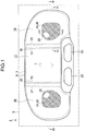
- a front side shown in Figs. 1 and 2 becomes a bottom side (i.e., lower side).
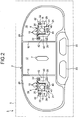
- a back side shown in Figs. 6 to 9 becomes a planar side (i.e., upper side).
- a vehicle interior lamp 1 according to the embodiment includes a lamp housing 2, an inner lens 3 and an outer lens 4 as lamp lenses, a lamp cover 5, a spotlight source 6 having a semiconductor-type light source having light directionality, a wide-light source 7, and a bracket 21.
- the lamp housing 2 of the embodiment is a lighttight member.
- the lamp housing 2 is of a U-shape in section with one side (i.e. front side) open and another side (i.e. back side) closed.
- the lamp housing 2 has an opening 8, and a step 9 is integrally formed along an edge of the opening 8.
- the lamp cover 5 of the embodiment is a lighttight member.
- the lamp cover 5 has a cover-like shape.
- an opening 10 of approximately the same size as that of the opening 8 of the lamp housing 2 is provided.
- an inner step 11 is integrally formed along an edge of the opening 10 of the lamp cover 5.
- the step 9 of the lamp housing 2 fits around the inner step 11 of the lamp cover 5. In a fitted state, the lamp housing 2 is secured to the lamp cover 5 with a fixing unit (not shown) such as a screw or an elastic engagement member.
- the outer lens 4 of the embodiment is an optically-transparent resin member.
- the outer lens 4 is of a shallow U-shape in section with one side (i.e., back side) open and another side (i.e., front side) closed.
- the outer lens 4 has an opening 12, and a wall 13 is integrally formed along an edge of the opening 12.
- the inner lens 3 is of a platelike shape.
- the inner lens 3 is fitted inside the wall 13 of the opening 12 of the outer lens 4. In a fitted state, the inner lens 3 is secured to the outer lens 4 with a fixing unit (not shown) such as an elastic engagement member.
- an outer step 14 is formed integrally.
- the wall 13 of the outer lens 4 to which the inner lens 3 is secured fits into the outer step 14 of the lamp cover 5 to which the lamp housing 2 is secured.
- the outer lens 4 is secured to the lamp cover 5 with a fixing unit (not shown) such as an elastic engagement member.
- a lamp chamber is delimited by the lamp housing 2, the inner lens 3, the outer lens 4, and the lamp cover 5.
- An interior of the lamp chamber is further divided into right and left spotlight lamp chambers 16, 16 and a central wide-light lamp chamber 17 by two partition walls 15 at right and left ends of the lamp housing 2.
- the spotlight source 6 is a semiconductor-type light source such as an LED having light directionality.
- the spotlight source 6 has a unit structure including a main body, a light-radiating unit which is provided on one surface of the main body to radiate light, and a fin-like heat sink member 19 which is provided on another surface of the main body and has a fin-like shape.
- the spotlight source 6 includes a chip (not shown) of a semiconductor-type light source, a substrate (not shown) on which the chip is mounted, a lens 18 which covers the chip and the substrate, the fin-like heat sink member 19 which is directly or indirectly attached to the substrate via a heat-conductive member (not shown) and has plural fins (four fins in the embodiment), and a resin casing 20 which holds the chip, the substrate, the lens 18, and the heat sink member 19.
- the chip, the substrate, and the casing 20 constitute the main body of the spotlight source 6, whereas the lens 18 constitutes the light-radiating unit of the spotlight source 6.
- Each of the spotlight sources 6, 6 is secured to the lamp housing 2 via the bracket 21 with a screw 22 or a caulking 28.
- the spotlight sources 6, 6 are arranged in the right and the left spotlight lamp chambers 16, 16, respectively.
- the lens 18 of the spotlight source 6 is arranged at the side of the inner lens 3 and the outer lens 4.
- the heat sink member 19 of the spotlight source 6 is arranged at the side of the lamp housing 2.
- the bracket 21 has functions of securing the spotlight source 6, and of guiding and discharging heat generated by the spotlight source 6 in a predetermined direction.
- a light axis (i.e., axis on which light directionality is 0°) of the spotlight source 6 which is configured with the semiconductor-type light source such as an LED having light directionality is aligned with a light-radiation direction Z-Z of the spotlight source 6.
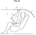
- the light-radiation direction Z-Z is inclined to an attachment surface of a ceiling trim T of an interior R of a vehicle (automobile) C as shown in Fig. 10 . Further, the light-radiation direction Z-Z extends along a line connecting a predetermined point (which is a substantially central point) in a range E illuminated by spotlight L4 radiated from the spotlight source 6, and a substantially central point of the chip.
- the range E illuminated by the spotlight L4 radiated from the spotlight source 6 is, for example, an area at a hand of a person P who sits on a backseat when the vehicle interior lamp 1 is attached to the ceiling trim T above the backseat.
- character "G" indicates a rear window glass.
- the lamp housing 2 has a bottom plate 29 in a closed portion as an attachment surface, which is attached to the attachment surface of the ceiling trim T of the interior R of the vehicle (automobile) C.
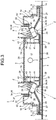
- the spotlight source 6 which is arranged in the lamp chamber 16 and secured to the lamp housing 2 is inclined to the bottom plate 29 of the attachment surface of the lamp housing 2 as shown in Figs. 3 to 5 .
- the light axis of the spotlight source 6 i.e., the light-radiation direction Z-Z of the spotlight source 6) is inclined to the bottom plate 29 of the attachment surface of the lamp housing 2.
- the fin-like heat sink member 19 of the spotlight source 6 is projected toward an opposite side of the lens 18 from another side of the main body substantially parallel to the light axis of the spotlight source 6 (i.e., the light-radiation direction Z-Z of the spotlight source 6). Therefore, the fin-like heat sink member 19 of the spotlight source 6 is inclined to the bottom plate 29 of the attachment surface of the lamp housing 2. Since the spotlight source 6 is inclined to the bottom plate 29 of the lamp housing 2, the fin-like heat sink member 19 is similarly inclined to the bottom plate 29 of the lamp housing 2. As shown in Figs.
- the fin-like heat sink members 19, 19 of the right and the left spotlight sources 6, 6 are inclined inwardly toward each other to the side of a switch 23 when viewed from the back side of the vehicle interior lamp 1. Further, when viewed along a longitudinal section of the vehicle interior lamp 1 as shown in Figs. 3 and 4 , the fin-like heat sink members 19, 19 of the right and the left spotlight sources 6, 6 are inclined inwardly toward each other. Further, when viewed in a section along a short-side direction of the vehicle interior lamp 1 as shown in Fig. 5 , a longitudinal direction of the fin-like heat sink member 19 of the spotlight source 6 is inclined from inside the lamp chamber 16 to the lamp housing 2.
- the wide-light source 7 is a bulb-type light source and of a boat-like shape.
- the wide-light source 7 is secured to the lamp housing 2 with an electrode-cum-holder (not shown). As a result, the wide-light source 7 is arranged in the central wide-light lamp chamber 17.
- the spotlight sources 6, 6 are electrically connected to a side of a power source via switches 23, 23 by harnesses 33, 33.
- the wide-light source 7 is electrically connected to the side of the power source by a harness (not shown) via a door switch (not shown) which is turned on and off when a door of the vehicle is opened or closed or via a main switch (not shown) which is turned on and off by a driver.
- frustum-like depressions 24, 24, for example, circular-truncated-cone-like depressions are formed at positions corresponding to the spotlight sources 6, 6 arranged inside the right and the left spotlight lamp chambers 16, 16.
- a central axis of the depression 24 substantially coincides with the light-radiation direction Z-Z.
- radiation holes 25, 25 are formed to radiate the light from the spotlight sources 6, 6 onto the interior of the vehicle through the outer lens 4.
- a portion of the lens 18 serving as the light-radiating unit of the spotlight source 6 is projected outward from the radiation hole 25 (i.e., toward the side of the outer lens 4).
- the inner lens 3 as the lamp lens is made by two-color molding and has an outer side formed of a resin member 26 that has a light-guiding function, and an inner side formed of a lighttight resin member 27.
- the outer member 26 has an incident surface (not shown) for making the light from the spotlight source 6 come into the outer member 26 along the edge of the radiation hole 25.
- the outer member 26 further has a light-diffusing portion 30 for diffusing the light from the spotlight source 6 on a surface of the depression 24 of the inner lens 3.
- the light-diffusing portion 30 has numerous extremely small bumps formed through honing or grain finish, for example.
- the light-diffusing portion 30 is formed within a range where the surface (inclined inner surface) of the depression 24 extends, as shown by hatching in Fig. 1 .
- a light-shielding rib 31 is integrally formed so as to oppose to the partition wall 15.
- the light-shielding rib 31 prevents the light from the spotlight sources 6, 6 arranged in the right and the left spotlight lamp chambers 16, 16 from leaking into the central wide-light lamp chamber 17.
- the light-shielding rib 31 prevents the light from the wide-light source 7 arranged in the central wide-light lamp chamber 17 from leaking into the right and the left spotlight lamp chambers 16, 16.
- the inner member 27 of the inner lens 3 has an opening 32 formed at a position corresponding to the central wide-light lamp chamber 17.
- the opening 32 of the inner member 27, which is a lighttight resin member, serves to pass the light from the wide-light source 7 arranged in the central wide-light lamp chamber 17 through the outer member 26 of the inner lens 3 and the outer lens 4 to illuminate the interior of the vehicle.
- the bottom plate 29 of the lamp housing 2 has backward-heat-discharging openings 34, 34 and lateral-heat-discharging openings 35, 35 formed at positions corresponding to the spotlight sources 6, 6.
- the backward-heat-discharging openings 34, 34 and the lateral-heat-discharging openings 35, 35 are communicated with a space extending in a direction along the inclination of the fin-like heat sink members 19, 19 of the right and the left spotlight sources 6, 6 (in other words, in a direction inclined inwardly to the side of the switch 23).
- the backward-heat-discharging opening 34 and the lateral-heat-discharging opening 35 may together form one big opening.
- the heat sink member 19 of the spotlight source 6 is arranged in the backward-heat-discharging opening 34 and the lateral-heat-discharging opening 35. Further, as shown in Fig. 5 , the longitudinal direction of the fin of the heat sink member 19 is inclined from inside the lamp chamber 16 toward the backward-heat-discharging opening 34 and the lateral-heat-discharging opening 35.
- a step is formed down to the side of the lamp chamber 16.
- the step forms heat guiding paths 36, 36.
- the heat guiding paths 36, 36 are arranged in a predetermined direction from portions of the edges of the lateral-heat-discharging openings 35, 35, in other words, in an inward direction towards the side of the switch 23.
- a heat-guiding protrusion (rib) 37 is formed integrally.
- the heat guiding path 36 serves also as a wiring path that houses the harness 33 for wiring. Therefore, the heat guiding path 36 may be a depression, a groove, or a notch other than the step as far as the heat guiding path 36 can house the harness 33 for wiring.
- the heat guiding path 36 has a holder to hold the harness 33.
- the holder includes, for example, a notch 38, an elastic claw 39, and a fixing claw 40.
- the bracket 21 includes, as shown in Figs. 2 to 5 , a fitting portion 41, a fixing portion 42, and a wall portion 43.
- the bracket 21 is a strong, elastic member with high heat conductivity, such as a thin steel plate.
- the fitting portion 41 is of a U-like shape and securely fits around the casing 20 of the main body of the spotlight source 6.
- the fitting portion 41 covers an area around the lens 18 on one surface and left and right side surfaces of the casing 20.
- an elastic fitting unit may be provided to each of the casing 20 and the fitting portion 41, so that the elastic fitting units elastically fit with each other so as to increase a fixing force of the spotlight source 6 and the bracket 21.
- a fitting hole (not shown) may be formed in the casing 20 while a fitting boss (not shown) may be formed on the fitting portion 41, and the fitting boss may be elastically fitted into the fitting hole.
- the fixing portion 42 is formed as a folded side part of the fitting portion and is integral to the fitting portion 41, or formed as an integral folded portion extending from the other side of the fitting portion 41 via the wall portion 43.
- the lens 18 of the light-radiating unit of the spotlight source 6 is arranged at the side of the inner lens 3 and the outer lens 4 of the lamp lens, whereas the heat sink member 19 of the spotlight source 6 is arranged at the side of the backward-heat-discharging opening 34 and the lateral-heat-discharging opening 35 of the lamp housing 2.
- the fixing portion 42 is secured by the screw 22 or the caulking 28 to the edges of the backward-heat-discharging opening 34 and the lateral-heat-discharging opening 35 of the lamp housing 2.
- the fixing portion 42 has a width substantially equal to the width of the fitting portion 41, or the wall portion 43.
- the wall portion 43 is arranged between the other side of the fitting portion 41 and the fixing portion 42.
- the wall portion 43 is arranged from the spotlight source 6 up to the edges of the backward-heat-discharging opening 34 and the lateral-heat-discharging opening 35.
- the wall portion 43 guides the heat generated from the spotlight source 6 to the backward-heat-discharging opening 34 and the lateral-heat-discharging opening 35. Further, the wall portion 43 prevents the heat generated from the spotlight source 6 from leaking outside a space enclosed by the wall portion 43, for example, to the side of the lens 18 of the spotlight source 6.
- a positioning boss 44 is integrally formed as a long boss serving as a positioning unit.
- a positioning hole 45 is formed as an elongated hole in the fitting portion 41 of the bracket 21.
- the vehicle interior lamp 1 of the embodiment has the above-described configuration. Functions thereof will be described below.
- the vehicle interior lamp 1 is attached to the ceiling trim T over the backseat in the interior R of the vehicle (automobile) C as shown in Fig. 10 , for example, so that the side of the switch 23 is located at the opposite side from the rear window glass G.
- the spotlight source 6 lights up, and direct light L4 as spotlight passes through the lens 18, through the truncated-circular-cone-shaped depression 24 of the inner lens 3, and the outer lens 4, and illuminates the predetermined range E of the interior of the vehicle.
- a part of the light (not shown) from the lens 18 of the spotlight source 6 passes through the radiation hole 25 of the inner lens 3 and hits the light-diffusing portion 30 on the surface of the truncated-circular-cone-shaped depression 24 to be diffused. Further, a part of the light (not shown) from the lens 18 of the spotlight source 6 comes into the outer member 26 through the incident surface of the outer member 26 of the inner lens 3. The incident light coming into the outer member 26 through the incident surface is repeatedly reflected at an outer surface (surface) of the outer member 26 and a boundary between the outer member 26 and the inner member 27 due to a light-guiding function of the outer member 26, and guided in the outer member 26. At the same time, a part of the light (not shown) is emitted to the outside from the outer surface of the outer member 26.
- the wide-light source 7 lights up, and the wide light from the wide-light source 7 passes through the outer member 26 of the inner lens 2 and the outer lens 4, so as to widely illuminate a predetermined range in the interior of the vehicle.
- the spotlight source 6 When the spotlight source 6 is turned on, the heat is generated in the casing 20 of the main body of the spotlight source 6. The heat is transferred to the heat sink member 19 from the casing 20 of the main body of the spotlight source 6. The heat transferred to the heat sink member 19 is discharged outside the lamp chamber 16 from inside the lamp chamber 16 through the backward-heat-discharging opening 34 and the lateral-heat-discharging opening 35 along the longitudinal direction of the fin of the heat sink member 19 as shown by a solid arrow shown in Figs. 3 , 5 , and 6 .
- the heat generated in the casing 20 of the main body of the spotlight source 6 is prevented from leaking out from a space enclosed by the wall portion 43, e.g., to the side of the lens 18 of the spotlight source 6, by the wall portion 43 of the bracket 21.
- the heat generated in the casing 20 of the main body of the spotlight source 6 is guided from inside the lamp chamber 16 to the backward-heat-discharging opening 34 and the lateral-heat-discharging opening 35 by the wall portion 43 of the bracket 21.
- the heat guided from inside the lamp chamber 16 to the backward-heat-discharging opening 34 and the lateral-heat-discharging opening 35 passes through the backward-heat-discharging opening 34 and the lateral-heat-discharging opening 35, and is discharged outside the lamp chamber 16.
- the heat discharged outside the lamp chamber 16 is guided from the lateral-heat-discharging opening 35 along the heat guiding path 36 to the side of the switch 23 at the opposite side from the rear window glass G. Further, the heat discharged from the heat sink member 19 is guided by the heat-guiding protrusion 37 on the edges of the backward-heat-discharging opening 34, the lateral-heat-discharging opening 35, and the heat guiding path 36 to the side of the switch 23 opposite to the rear window glass G.
- the vehicle interior lamp 1 of the embodiment has the configuration and functions as described above. Effects thereof will be described below.
- the heat generated in the main body of the spotlight source 6 is efficiently discharged through the heat sink member 19 inside the lamp chamber 16, and the backward-heat-discharging opening 34 and the lateral-heat-discharging opening 35 of the lamp housing 2 to the outside of the lamp chamber 16.
- the heat generated in the casing 20 of the main body of the spotlight source 6 is transferred from inside the lamp chamber 16 to the side of the backward-heat-discharging opening 34 and the lateral-heat-discharging opening 35 of the lamp housing 2 along the longitudinal direction of the fin of the heat sink member 19 in the heat sink member 19, as shown by a solid arrow in Fig.
- the vehicle interior lamp 1 of the embodiment takes full measures against heat of the semiconductor-type light source which is the spotlight source 6, whereby a high-output semiconductor-type light source can be used.
- the light axis of the spotlight source 6 arranged inside the lamp chamber 16 is substantially parallel to the longitudinal direction of the fin of the heat sink member 19.
- the light-radiation direction Z-Z of the spotlight source 6 is inclined to the attachment surface of the ceiling trim T of the interior R of the vehicle (automobile) C, i.e., the bottom plate 29 of the attachment surface of the lamp housing 2. Therefore, in the vehicle interior lamp 1 of the embodiment, when the light axis of the spotlight source 6 is aligned with the light-radiation direction Z-Z of the spotlight source 6, the light axis of the spotlight source 6 is inclined to the bottom plate 29 of the attachment surface of the lamp housing 2.
- the vehicle interior lamp 1 of the embodiment can readily and securely incline the longitudinal direction of the fin of the heat sink member 19 from the inside of the lamp chamber 16 to the backward-heat-discharging opening 34 and the lateral-heat-discharging opening 35. Therefore, the vehicle interior lamp 1 of the embodiment can efficiently discharge the heat generated in the casing 20 of the main body of the spotlight source 6 from inside the lamp chamber 16 along the longitudinal direction of the fin of the heat sink member 19 which is inclined toward the backward-heat-discharging opening 34 and the lateral-heat-discharging opening 35, from inside the lamp chamber 16 through the backward-heat-discharging opening 34 and the lateral-heat-discharging opening 35 to the outside of the lamp chamber 16.
- the vehicle interior lamp 1 of the embodiment can provide the spotlight with high light directionality readily and securely since the spotlight source 6 is configured with a semiconductor-type light source such as an LED having light directionality. Further, since the vehicle interior lamp 1 of the embodiment can provide the spotlight with high light directionality, glare can be prevented from annoying people other than a user of the spotlight.
- the heat generated in the casing 20 of the main body of the spotlight source 6 is guided in a predetermined direction via the heat sink member 19 and through the backward-heat-discharging opening 34 and the lateral-heat-discharging opening 35 of the lamp housing 2 following the heat-guiding path 36, and thereby efficiently discharged outside the lamp chamber 16.
- the vehicle interior lamp 1 of the embodiment takes full measures against the heat of the semiconductor-type light source which is the spotlight source 6, whereby a high-output semiconductor-type light source can be used.
- the vehicle interior lamp 1 of the embodiment can guide the heat of the spotlight source 6 by the heat guiding path 36 in a predetermined direction, e.g., direction to the side of the switch 23 at the opposite side of the rear window glass G in the embodiment.
- the vehicle interior lamp 1 of the embodiment can minimize the inconvenience caused by the discharge of the heat from the spotlight source 6.
- the vehicle interior lamp 1 of the embodiment can prevent the fogging of the rear window glass G by guiding the heat of the spotlight source 6 to the opposite side from the rear window glass G.
- the vehicle interior lamp 1 of the embodiment has the heat-guiding protrusion 37 along the edges of the backward-heat-discharging opening 34, the lateral-heat-discharging opening 35, and the heat-guiding path 36, the vehicle interior lamp 1 of the embodiment can guide the heat of the spotlight source 6 in a predetermined direction even more securely. Still further, since the vehicle interior lamp 1 of the embodiment has the heat-guiding protrusion 37 along the edges of the backward-heat-discharging opening 34, the lateral-heat-discharging opening 35, and the heat-guiding path 36, the strength of the lamp housing 2 can be increased.
- the heat-guiding path 36 is also used as the wiring path through which the harness 33 is arranged and electrically connected to the spotlight source 6.
- the vehicle interior lamp 1 of the embodiment has a fixing unit such as the notch 38, the elastic claw 39, and the fixing claw 40 in the heat-guiding path 36 to secure the harness 33. Therefore, the vehicle interior lamp 1 of the embodiment can arrange the harness 33 of the spotlight source 6 readily and securely in a shortest possible distance. Still further, the vehicle interior lamp 1 of the embodiment simplifies a wiring work of the harness 33 of the spotlight source 6, and shortens the harness 33, whereby manufacturing cost can be decreased.
- the harness 33 can be arranged in a shortest possible distance.
- the fixing unit of the harness 33 such as the notch 38, the elastic claw 39, and the fixing claw 40 can be provided outside the lamp housing 2 in the heat-guiding path 36, which is a wiring path of the step.
- the wall portion 43 of the bracket 21 can prevent the heat generated from the spotlight source 6 from leaking outside the space surrounded by the wall portion 43, e.g., to the side of the lens 18 of the spotlight source 6.
- the vehicle interior lamp 1 of the embodiment efficiently discharges the heat generated from the spotlight source 6 by guiding the heat from the spotlight source 6 along the wall portion 43 of the bracket 21 to the backward-heat-discharging opening 34 and the lateral-heat-discharging opening 35 of the lamp housing 2, and through the backward-heat-discharging opening 34 and the lateral-heat-discharging opening 35 to the outside of the lamp chamber 16.
- the vehicle interior lamp 1 of the embodiment takes full measures against heat of the semiconductor-type light source, which is the spotlight source 6, whereby a high-output semiconductor-type light source can be used.
- the spotlight source 6 is secured to the lamp housing 2 by the bracket 21, whereby the spotlight source 6 can be secured to the lamp housing 2 with a high degree of accuracy. Specifically, even when the light axis of the spotlight source 6 is aligned with the light-radiation direction Z-Z of the spotlight source 6, and the spotlight source 6 is secured to the bottom plate 29 of the attachment surface of the lamp housing 2 in an inclined state, the spotlight source 6 can be secured to the lamp housing 2 in an inclined state with a high degree of accuracy.
- the width of the fixing portion 42 of the bracket 21 is substantially equal to the width of the fitting portion 41 or the wall portion 43 of the bracket 21, and therefore, a sufficient area can be secured for fixing the fixing portion 42 of the bracket 21 to the lamp housing 2.
- the spotlight source 6 can be secured to the lamp housing 2 with a still higher degree of accuracy.
- the bracket 21 is configured with a strong, elastic member having a high heat conductivity, whereby the effect of discharging the heat from the spotlight source 6 can be further enhanced, and the spotlight source 6 can be securely fixed to the lamp housing 2 via the bracket 21.
- the vehicle interior lamp 1 is explained as being attached to the ceiling trim T over the backseat near the rear window glass G.
- the present invention can be applied to a vehicle interior lamp attached to a position other than the ceiling trim T over the backseat near the rear window glass G, e.g., a ceiling trim over a front seat near a front window glass.
- the positioning unit includes the positioning protrusion 44 which is an elongated boss and the positioning hole 45 which is an elongated hole.
- the positioning unit may be configured with an element other than the positioning protrusion 44 as the elongated boss and the positioning hole 45 as the elongated hole.
- the positioning unit may be configured with one or more small circular protrusion(s) and one or more small circular hole(s).
Landscapes
- Engineering & Computer Science (AREA)
- General Engineering & Computer Science (AREA)
- Mechanical Engineering (AREA)
- Arrangements Of Lighting Devices For Vehicle Interiors, Mounting And Supporting Thereof, Circuits Therefore (AREA)
- Arrangement Of Elements, Cooling, Sealing, Or The Like Of Lighting Devices (AREA)
- Non-Portable Lighting Devices Or Systems Thereof (AREA)
Claims (8)
- Fahrzeug-Innenleuchte (1), die umfasst:eine Lichtquelle (6), die eine Halbleiter-Lichtquelle mit gerichtetem Licht ist, wobei die Lichtquelle (6) eine Bauteil-Struktur hat, die einen Hauptkörper (20), eine Lichtausstrahlungs-Einheit (18), die sich in dem Hauptkörper (20) befindet und Licht ausstrahlt, sowie ein Wärmesenken-Element (19) enthält, das sich in dem Hauptkörper (20) befindet;ein Leuchten-Gehäuse (2), das eine Wärmeableit-Öffnung (34, 35) aufweist, die dazu dient, in dem Wärmesenken-Element (19) erzeugte Wärme von dem Leuchten-Gehäuse (2) nach außen zu übertragen;eine Leuchten-Linse (3, 4); undeine Leuchten-Kammer (16), die durch das Leuchten-Gehäuse (2) und die Leuchten-Linse (3, 4) begrenzt wird,dadurch gekennzeichnet, dassdie Wärmeableit-Öffnung (34, 35) der Leuchten-Linse (3, 4) gegenüberliegend an einer hinteren Seite der Lichtquelle (6) angeordnet ist und das Wärmesenken-Element (19) in der Wärmeableit-Öffnung (34, 35) angeordnet ist.
- Fahrzeug-Innenleuchte nach Anspruch 1, dadurch gekennzeichnet, dass das Leuchten-Gehäuse (2) einen Wärmeleit-Weg (36) hat, der in einer vorgegebenen Richtung von einem Abschnitt eines Randes der Wärmeableit-Öffnung (34, 35) aus verlaufend angeordnet ist.
- Fahrzeug-Innenleuchte nach Anspruch 1 oder 2, dadurch gekennzeichnet, dass sie des Weiteren einen Wärmeleit-Vorsprung (37) umfasst, der an einem Rand der Wärmeableit-Öffnung (34, 35) und einem Rand des Wärmeleit-Weges (36) angeordnet ist.
- Fahrzeug-Innenleuchte nach einem der Ansprüche 1 bis 3, dadurch gekennzeichnet, dass das Wärmesenken-Element (19) der Lichtquelle (6) eine rippenartige Form hat und die Lichtquelle (6) in der Leuchten-Kammer (16) in einem relativ zu einer Anbringungsfläche (29) des Leuchten-Gehäuses (2) geneigten Zustand so angeordnet ist, dass eine Längsrichtung einer Rippe des Wärmesenken-Elementes (19) in einer Richtung von einem Innenraum der Leuchten-Kammer (16) zu der Wärmeableit-Öffnung (34, 35) geneigt ist.
- Fahrzeug-Innenleuchte nach einem der Ansprüche 1 bis 4, dadurch gekennzeichnet, dass die Lichtquelle (6) über einen Kabelbaum (33) elektrisch mit einer Seite einer Stromquelle verbunden ist, und
der Kabelbaum (33) über die Wärmeableit-Öffnung (34 und 35) von dem Innenraum der Leuchten-Kammer (16) aus der Leuchten-Kammer (16) nach außen verlaufend angeordnet ist. - Fahrzeug-Innenleuchte nach einem der Ansprüche 1 bis 5, dadurch gekennzeichnet, dass das Leuchten-Gehäuse (2) einen Absatz aufweist, der an einem Abschnitt des Randes der Wärmeableit-Öffnung (34, 35) eine Stufe nach unten angeordnet ist, und
der Absatz einen Verdrahtungsweg bildet, an dem der Kabelbaum (33) angeordnet ist. - Fahrzeug-Innenleuchte nach einem der Ansprüche 1 bis 6, dadurch gekennzeichnet, dass der Absatz eine Befestigungs-Einheit (38, 39, 40) aufweist, die an dem Verdrahtungsweg angeordnet ist, um den Kabelbaum (33) zu fixieren.
- Fahrzeug-Innenleuchte (1) nach einem der Ansprüche 4 bis 7, dadurch gekennzeichnet, dass das Wärmesenken-Element (19) eine Vielzahl von Rippen aufweist.
Applications Claiming Priority (1)
| Application Number | Priority Date | Filing Date | Title |
|---|---|---|---|
| JP2006228367A JP4706598B2 (ja) | 2006-08-24 | 2006-08-24 | 車両用ルームランプ |
Publications (2)
| Publication Number | Publication Date |
|---|---|
| EP1892462A1 EP1892462A1 (de) | 2008-02-27 |
| EP1892462B1 true EP1892462B1 (de) | 2017-10-11 |
Family
ID=38626641
Family Applications (1)
| Application Number | Title | Priority Date | Filing Date |
|---|---|---|---|
| EP07015998.3A Ceased EP1892462B1 (de) | 2006-08-24 | 2007-08-14 | Deckenleuchte für Fahrzeuge |
Country Status (4)
| Country | Link |
|---|---|
| US (1) | US7674027B2 (de) |
| EP (1) | EP1892462B1 (de) |
| JP (1) | JP4706598B2 (de) |
| CN (1) | CN100549516C (de) |
Families Citing this family (12)
| Publication number | Priority date | Publication date | Assignee | Title |
|---|---|---|---|---|
| JP4831109B2 (ja) | 2008-04-08 | 2011-12-07 | 豊田合成株式会社 | 車両室内用照明装置 |
| JP5169806B2 (ja) | 2008-12-25 | 2013-03-27 | 豊田合成株式会社 | 照明装置 |
| JP5262755B2 (ja) | 2009-01-27 | 2013-08-14 | 豊田合成株式会社 | 車両室内照明装置 |
| JP2013086566A (ja) * | 2011-10-14 | 2013-05-13 | Yazaki Corp | ランプユニットの製造方法及びランプユニット |
| JP6601993B2 (ja) * | 2013-05-29 | 2019-11-06 | 三菱電機株式会社 | 照明器具 |
| CN104949026A (zh) * | 2014-03-25 | 2015-09-30 | 东芝照明技术株式会社 | 车室内照明装置 |
| JP6323910B2 (ja) * | 2014-09-29 | 2018-05-16 | パナソニック エコソリューションズ朝日株式会社 | 車両用室内灯およびそれを備えた車両 |
| JP2018192881A (ja) * | 2017-05-16 | 2018-12-06 | 矢崎総業株式会社 | 室内照明灯 |
| US10106078B1 (en) * | 2017-10-20 | 2018-10-23 | Ford Global Technologies, Llc | Vehicle lamp assembly |
| CN115210499B (zh) * | 2020-05-08 | 2024-02-09 | 星和电机株式会社 | 照明装置 |
| JP7556375B2 (ja) * | 2022-04-20 | 2024-09-26 | トヨタ自動車株式会社 | 車室内照明装置 |
| JP2025063753A (ja) * | 2023-10-04 | 2025-04-16 | ミネベアミツミ株式会社 | 車両室内照明装置 |
Family Cites Families (17)
| Publication number | Priority date | Publication date | Assignee | Title |
|---|---|---|---|---|
| JPS58126231A (ja) * | 1982-01-22 | 1983-07-27 | Nissan Motor Co Ltd | 室内灯 |
| JPH01289729A (ja) * | 1988-05-17 | 1989-11-21 | Koito Mfg Co Ltd | 車輌用室内灯 |
| US6517218B2 (en) * | 2000-03-31 | 2003-02-11 | Relume Corporation | LED integrated heat sink |
| JP2002124123A (ja) * | 2000-10-17 | 2002-04-26 | Denso Corp | 車両用前照灯 |
| JP2002172977A (ja) * | 2000-12-05 | 2002-06-18 | Teeantee:Kk | 車両用室内灯 |
| ES2287266T3 (es) * | 2001-01-23 | 2007-12-16 | Donnelly Corporation | Sistema de iluminacion de vehiculos mejorado. |
| JP2002331868A (ja) | 2001-05-10 | 2002-11-19 | Ichikoh Ind Ltd | 車両用ルームランプ |
| US7093965B2 (en) * | 2001-07-09 | 2006-08-22 | Roger L Veldman | Automotive lighting assembly with decreased operating temperature |
| MXPA04001719A (es) * | 2001-08-31 | 2004-05-31 | Gentex Corp | Montaje de lampara de vehiculo con disipador termico. |
| JP2004241191A (ja) * | 2003-02-04 | 2004-08-26 | Koito Mfg Co Ltd | 口金付き電球 |
| DE10307147A1 (de) * | 2003-02-20 | 2004-09-23 | Airbus Deutschland Gmbh | Leseleuchte für Flugzeugkabinen |
| US7093964B2 (en) * | 2004-11-01 | 2006-08-22 | Federal-Mogul World Wide, Inc. | Compact, low-level vehicle interior lamp assembly |
| JP2006232185A (ja) * | 2005-02-28 | 2006-09-07 | Toyoda Gosei Co Ltd | 車両室内用の間接照明装置 |
| JP2006267774A (ja) * | 2005-03-25 | 2006-10-05 | Dainippon Printing Co Ltd | 露光装置 |
| KR100699149B1 (ko) * | 2005-05-24 | 2007-03-22 | 엘지전자 주식회사 | 영상투사기의 배기 도어 개폐장치 |
| US7307391B2 (en) * | 2006-02-09 | 2007-12-11 | Led Smart Inc. | LED lighting system |
| JP4508172B2 (ja) * | 2006-08-24 | 2010-07-21 | 市光工業株式会社 | 車両用ルームランプ |
-
2006
- 2006-08-24 JP JP2006228367A patent/JP4706598B2/ja not_active Expired - Fee Related
-
2007
- 2007-08-14 EP EP07015998.3A patent/EP1892462B1/de not_active Ceased
- 2007-08-14 US US11/889,490 patent/US7674027B2/en not_active Expired - Fee Related
- 2007-08-21 CN CNB2007101465773A patent/CN100549516C/zh not_active Expired - Fee Related
Non-Patent Citations (1)
| Title |
|---|
| None * |
Also Published As
| Publication number | Publication date |
|---|---|
| EP1892462A1 (de) | 2008-02-27 |
| CN101131233A (zh) | 2008-02-27 |
| CN100549516C (zh) | 2009-10-14 |
| US20080049435A1 (en) | 2008-02-28 |
| JP2008053065A (ja) | 2008-03-06 |
| US7674027B2 (en) | 2010-03-09 |
| JP4706598B2 (ja) | 2011-06-22 |
Similar Documents
| Publication | Publication Date | Title |
|---|---|---|
| EP1892148B1 (de) | Deckenleuchte für Fahrzeuge | |
| EP1892462B1 (de) | Deckenleuchte für Fahrzeuge | |
| US7665872B2 (en) | Vehicle headlamp | |
| US4733335A (en) | Vehicular lamp | |
| US8303146B2 (en) | Side turn signal lamp | |
| US7699511B2 (en) | Door mirror with turn lamp | |
| CN101793371B (zh) | 车辆用灯具 | |
| US20130141930A1 (en) | Vehicular headlamp | |
| JP4700081B2 (ja) | 車両用照明装置 | |
| JP4737106B2 (ja) | 車両用灯具 | |
| US7281822B2 (en) | Outside mirror apparatus for vehicle and illuminating unit for outside mirror apparatus | |
| US20180195682A1 (en) | Vehicle lighting assembly | |
| KR101092693B1 (ko) | 헤드램프용 led 광학장치 | |
| JP2011183958A (ja) | 車両用サンバイザ | |
| JP6931553B2 (ja) | 車両用灯具 | |
| US7674024B2 (en) | Interior illumination lamp | |
| JP2008049840A (ja) | 車両用ルームランプ | |
| US8147104B2 (en) | Vehicle room light apparatus | |
| JP2003118479A (ja) | 車両用ルームランプ | |
| JP2024534167A (ja) | 透光アセンブリおよび車両 | |
| JP2023070387A (ja) | 光源装置、及びこれを用いた車両用灯具 | |
| JP4605123B2 (ja) | 車両用ルームランプ | |
| JP4158628B2 (ja) | 車両用灯具 | |
| CN219775525U (zh) | 照明模组、灯装置以及车辆 | |
| KR20050047572A (ko) | 차량용 사이드 리피터 |
Legal Events
| Date | Code | Title | Description |
|---|---|---|---|
| PUAI | Public reference made under article 153(3) epc to a published international application that has entered the european phase |
Free format text: ORIGINAL CODE: 0009012 |
|
| AK | Designated contracting states |
Kind code of ref document: A1 Designated state(s): AT BE BG CH CY CZ DE DK EE ES FI FR GB GR HU IE IS IT LI LT LU LV MC MT NL PL PT RO SE SI SK TR |
|
| AX | Request for extension of the european patent |
Extension state: AL BA HR MK YU |
|
| 17P | Request for examination filed |
Effective date: 20080130 |
|
| 17Q | First examination report despatched |
Effective date: 20080402 |
|
| AKX | Designation fees paid |
Designated state(s): DE FR GB |
|
| RAP1 | Party data changed (applicant data changed or rights of an application transferred) |
Owner name: ICHIKOH INDUSTRIES, LTD. |
|
| RIC1 | Information provided on ipc code assigned before grant |
Ipc: F21V 29/00 20150101ALI20170217BHEP Ipc: F21V 29/74 20150101ALI20170217BHEP Ipc: B60Q 3/74 20170101ALI20170217BHEP Ipc: F21W 101/08 20060101ALN20170217BHEP Ipc: F21S 8/10 20060101AFI20170217BHEP |
|
| GRAP | Despatch of communication of intention to grant a patent |
Free format text: ORIGINAL CODE: EPIDOSNIGR1 |
|
| INTG | Intention to grant announced |
Effective date: 20170405 |
|
| RIC1 | Information provided on ipc code assigned before grant |
Ipc: F21V 29/74 20150101ALI20170328BHEP Ipc: B60Q 3/74 20170101ALI20170328BHEP Ipc: F21V 29/00 20150101ALI20170328BHEP Ipc: F21S 8/10 20060101AFI20170328BHEP Ipc: F21W 101/08 20060101ALN20170328BHEP |
|
| GRAS | Grant fee paid |
Free format text: ORIGINAL CODE: EPIDOSNIGR3 |
|
| GRAA | (expected) grant |
Free format text: ORIGINAL CODE: 0009210 |
|
| AK | Designated contracting states |
Kind code of ref document: B1 Designated state(s): DE FR GB |
|
| REG | Reference to a national code |
Ref country code: GB Ref legal event code: FG4D |
|
| REG | Reference to a national code |
Ref country code: DE Ref legal event code: R096 Ref document number: 602007052631 Country of ref document: DE |
|
| REG | Reference to a national code |
Ref country code: DE Ref legal event code: R079 Ref document number: 602007052631 Country of ref document: DE Free format text: PREVIOUS MAIN CLASS: F21S0008100000 Ipc: F21S0043000000 |
|
| REG | Reference to a national code |
Ref country code: DE Ref legal event code: R097 Ref document number: 602007052631 Country of ref document: DE |
|
| PLBE | No opposition filed within time limit |
Free format text: ORIGINAL CODE: 0009261 |
|
| STAA | Information on the status of an ep patent application or granted ep patent |
Free format text: STATUS: NO OPPOSITION FILED WITHIN TIME LIMIT |
|
| 26N | No opposition filed |
Effective date: 20180712 |
|
| PGFP | Annual fee paid to national office [announced via postgrant information from national office to epo] |
Ref country code: DE Payment date: 20180829 Year of fee payment: 12 |
|
| GBPC | Gb: european patent ceased through non-payment of renewal fee |
Effective date: 20180814 |
|
| PG25 | Lapsed in a contracting state [announced via postgrant information from national office to epo] |
Ref country code: FR Free format text: LAPSE BECAUSE OF NON-PAYMENT OF DUE FEES Effective date: 20180831 |
|
| PG25 | Lapsed in a contracting state [announced via postgrant information from national office to epo] |
Ref country code: GB Free format text: LAPSE BECAUSE OF NON-PAYMENT OF DUE FEES Effective date: 20180814 |
|
| REG | Reference to a national code |
Ref country code: DE Ref legal event code: R119 Ref document number: 602007052631 Country of ref document: DE |
|
| PG25 | Lapsed in a contracting state [announced via postgrant information from national office to epo] |
Ref country code: DE Free format text: LAPSE BECAUSE OF NON-PAYMENT OF DUE FEES Effective date: 20200303 |