EP1887936B1 - Interferometer für die qantitative phasenkontrast-bilddarstellung und tomographie mit einer inkohärenten polychromatischen röntgenstrahlenquelle - Google Patents
Interferometer für die qantitative phasenkontrast-bilddarstellung und tomographie mit einer inkohärenten polychromatischen röntgenstrahlenquelle Download PDFInfo
- Publication number
- EP1887936B1 EP1887936B1 EP06753957.7A EP06753957A EP1887936B1 EP 1887936 B1 EP1887936 B1 EP 1887936B1 EP 06753957 A EP06753957 A EP 06753957A EP 1887936 B1 EP1887936 B1 EP 1887936B1
- Authority
- EP
- European Patent Office
- Prior art keywords
- grating
- phase
- source
- beam splitter
- detector
- Prior art date
- Legal status (The legal status is an assumption and is not a legal conclusion. Google has not performed a legal analysis and makes no representation as to the accuracy of the status listed.)
- Active
Links
Images



Classifications
-
- A—HUMAN NECESSITIES
- A61—MEDICAL OR VETERINARY SCIENCE; HYGIENE
- A61B—DIAGNOSIS; SURGERY; IDENTIFICATION
- A61B6/00—Apparatus or devices for radiation diagnosis; Apparatus or devices for radiation diagnosis combined with radiation therapy equipment
- A61B6/42—Arrangements for detecting radiation specially adapted for radiation diagnosis
- A61B6/4208—Arrangements for detecting radiation specially adapted for radiation diagnosis characterised by using a particular type of detector
- A61B6/4233—Arrangements for detecting radiation specially adapted for radiation diagnosis characterised by using a particular type of detector using matrix detectors
-
- A—HUMAN NECESSITIES
- A61—MEDICAL OR VETERINARY SCIENCE; HYGIENE
- A61B—DIAGNOSIS; SURGERY; IDENTIFICATION
- A61B6/00—Apparatus or devices for radiation diagnosis; Apparatus or devices for radiation diagnosis combined with radiation therapy equipment
- A61B6/42—Arrangements for detecting radiation specially adapted for radiation diagnosis
- A61B6/4291—Arrangements for detecting radiation specially adapted for radiation diagnosis the detector being combined with a grid or grating
-
- A—HUMAN NECESSITIES
- A61—MEDICAL OR VETERINARY SCIENCE; HYGIENE
- A61B—DIAGNOSIS; SURGERY; IDENTIFICATION
- A61B6/00—Apparatus or devices for radiation diagnosis; Apparatus or devices for radiation diagnosis combined with radiation therapy equipment
- A61B6/48—Diagnostic techniques
- A61B6/484—Diagnostic techniques involving phase contrast X-ray imaging
-
- G—PHYSICS
- G01—MEASURING; TESTING
- G01N—INVESTIGATING OR ANALYSING MATERIALS BY DETERMINING THEIR CHEMICAL OR PHYSICAL PROPERTIES
- G01N23/00—Investigating or analysing materials by the use of wave or particle radiation, e.g. X-rays or neutrons, not covered by groups G01N3/00 – G01N17/00, G01N21/00 or G01N22/00
- G01N23/02—Investigating or analysing materials by the use of wave or particle radiation, e.g. X-rays or neutrons, not covered by groups G01N3/00 – G01N17/00, G01N21/00 or G01N22/00 by transmitting the radiation through the material
- G01N23/04—Investigating or analysing materials by the use of wave or particle radiation, e.g. X-rays or neutrons, not covered by groups G01N3/00 – G01N17/00, G01N21/00 or G01N22/00 by transmitting the radiation through the material and forming images of the material
- G01N23/041—Phase-contrast imaging, e.g. using grating interferometers
-
- A—HUMAN NECESSITIES
- A61—MEDICAL OR VETERINARY SCIENCE; HYGIENE
- A61B—DIAGNOSIS; SURGERY; IDENTIFICATION
- A61B6/00—Apparatus or devices for radiation diagnosis; Apparatus or devices for radiation diagnosis combined with radiation therapy equipment
- A61B6/06—Diaphragms
-
- A—HUMAN NECESSITIES
- A61—MEDICAL OR VETERINARY SCIENCE; HYGIENE
- A61B—DIAGNOSIS; SURGERY; IDENTIFICATION
- A61B6/00—Apparatus or devices for radiation diagnosis; Apparatus or devices for radiation diagnosis combined with radiation therapy equipment
- A61B6/40—Arrangements for generating radiation specially adapted for radiation diagnosis
- A61B6/4064—Arrangements for generating radiation specially adapted for radiation diagnosis specially adapted for producing a particular type of beam
- A61B6/4092—Arrangements for generating radiation specially adapted for radiation diagnosis specially adapted for producing a particular type of beam for producing synchrotron radiation
-
- A—HUMAN NECESSITIES
- A61—MEDICAL OR VETERINARY SCIENCE; HYGIENE
- A61B—DIAGNOSIS; SURGERY; IDENTIFICATION
- A61B6/00—Apparatus or devices for radiation diagnosis; Apparatus or devices for radiation diagnosis combined with radiation therapy equipment
- A61B6/50—Apparatus or devices for radiation diagnosis; Apparatus or devices for radiation diagnosis combined with radiation therapy equipment specially adapted for specific body parts; specially adapted for specific clinical applications
- A61B6/502—Apparatus or devices for radiation diagnosis; Apparatus or devices for radiation diagnosis combined with radiation therapy equipment specially adapted for specific body parts; specially adapted for specific clinical applications for diagnosis of breast, i.e. mammography
-
- G—PHYSICS
- G21—NUCLEAR PHYSICS; NUCLEAR ENGINEERING
- G21K—HANDLING OF PARTICLES OR IONISING RADIATION NOT OTHERWISE PROVIDED FOR; IRRADIATION DEVICES; GAMMA RAY OR X-RAY MICROSCOPES
- G21K2207/00—Particular details of imaging devices or methods using ionizing electromagnetic radiation such as X-rays or gamma rays
- G21K2207/005—Methods and devices obtaining contrast from non-absorbing interaction of the radiation with matter, e.g. phase contrast
Definitions
- the present invention relates to an interferometer for X-rays, in particular hard X-rays, for obtaining quantitative phase contrast images and measuring wavefront shapes.
- the cross section for absorption which generates the contrast in conventional radiography, is usually much smaller than that for elastic scattering.
- the elastic scattering causes a phase shift of the wave passing through matter. If, for example, 17.5-keV x-rays (which are commonly applied for mammography) pass through a 50- ⁇ m-thick sheet of biological tissue, the attenuation will only be a fraction of a percent, while the phase shift is close to n.
- the possibility to record the phase shift of x-rays opens the potential for greatly enhanced contrast and, in consequence, reduction of the applied x-ray dose. Reduction of the dose is desirable i) because of health risks for patients exposed to x-rays, and ii) because of the reduced exposure times.
- phase variations in the radiation behind the sample were developed in the past years. They can be classified into interferometric methods, techniques using an analyzer crystal, and free-space propagation methods. These methods differ in the nature of the signal recorded, the experimental setup, and the requirements on the illuminating radiation (especially its spatial coherence and monochromaticity). Although some of them yield excellent results for specific problems, none is very widely used. In particular, none of them has so far found medical diagnostics applications, which require a large field of view of many centimeters, the efficient use of broadband radiation as provided by laboratory x-ray generators and a reasonably compact setup. In addition to medical applications, any investigation of low contrast objects, e.g., in biology or materials science could benefit from exploiting phase contrast. It should be mentioned that an object embedded in a matrix of the same absorption coefficient is completely invisible in absorption contrast, while for the same sample significant differences in phase shift may occur.
- An interferometer for X-rays for obtaining phase contrast images employing X-ray Talbot interferometry comprising a compact broad energy X-ray source, a phase grating, and an amplitude grating placed closely in front of a detector is disclosed in MOMOSE A ET AL: "X-ray Talbot interferometry for medical phase imaging", PORTABLE SYNCHROTRON LIGHT SOURCES AND ADVANCED APPLICATIONS. INTERNATIONAL SYMPOSIUM ON PORTABLE SYNCHROTRON LIGHT SOURCES AND ADVANCED APPLICATIONS 13-14 JAN. 2004 SHIGA, JAPAN, no. 716, 13-14 January 2004, pages 156-159, XP002351238, AIP Conference Proceedings AIP USA ISSN: 0094-243X .
- US Patent 5,812,629 discloses an interferometer for X-rays for obtaining phase contrast images using a standard polychromatic X-ray source comprising the features of the preamble of claim 1.
- the phase of a wave cannot be measured directly, so any conversion of a phase shift into an intensity modulation has to depend on interference of two (or more) waves.
- the waves need to have a well-defined phase relation in time and space, i.e. sufficient temporal (longitudinal) coherence and spatial (transverse) coherence.
- Temporal coherence is related to the monochromaticity of the radiation.
- the longitudinal coherence length is ⁇ 2 / ⁇ .
- these beams only have a well-defined phase relation if the difference in optical path lengths is shorter than the longitudinal coherence length. While for visible laser light ⁇ 2 / ⁇ can extend over many meters, it is only in the order of a micron at hard x-ray wavelengths even when a crystal monochromator ( ⁇ / ⁇ ⁇ 10 4 ) is used.
- Spatial coherence is related to the size and distance of the source.
- an intrinsically incoherent and chaotic source e.g. a light bulb or a conventional x-ray tube
- transverse size c emitting at a wavelength ⁇
- the wave-front phase difference between two points lying in a plane normal to the optical axis and separated by a distance r is well defined only if the condition r ⁇ l / c is fulfilled.
- t ⁇ l / c is called the transverse coherence length.
- interference effects such as those used in the grating-based interferometers can only occur when the coherence length is approximately equal to or larger than the relevant length scale of the diffraction aperture or phase mask.
- the transverse coherence length at a distance of 1 m from the source is again in the order of only one micron.
- an interferometer for X-rays in particular hard X-rays, for obtaining quantitative phase contrast images, as defined in claim 1.
- This interferometer unifies all the requested requirements in using only a conventional X-ray source instead of a synchrotron source and in using only two different grating structures, one for diffracting the x-rays having passed through the object to be investigated, and the other one for delivering the spatially modulated detection sensitivity.
- the beam splitter is a phase grating, that is, a line grating or a two-dimensionally structured grating with low X-ray absorption, but considerable X-ray phase shift, preferably with a phase shift of ⁇ or odd multiples thereof.
- the phase grating may be made by deep etching into silicon or a polymer.
- the modulation of the detector sensitivity can be achieved by a one- or two-dimensional grating structure with high X-ray absorption contrast, placed immediately in front of the detector.
- This analyzer grating may serve as an anti-scatter grid, or an anti-scatter grid can be used as the analyzer grating.
- the absorption grating can be made by deposition of a heavy metal into the gaps of a low-absorbing structure.
- the distance between beam splitter and analyzer is chosen to be an odd fractional Talbot distance, given by the equation d n , sph .
- phase shift of the beam-splitter grating and the distance between beam splitter and analyzer can be adapted to a photon energy corresponding to an emission line of the Xray generator used as the source.
- a mechanism can be included to vary the angular orientation around the optical axis of the beam splitter with respect to the analyzer.
- a one- or two-dimensional phase stepping scan can be implemented by lateral transverse movement of the radiation source and/or an aperture located in front of the radiation source, and/or of the beam splitter, and/or of the analyzer, and/or by a tilt of the interferometer with respect to the X-ray source.
- the detector can be designed as being position-sensitive in two dimensions, whereby the lateral dimensions of the beam splitter and the analyzer cover a significant portion of the active area of the detector.
- a collimator can be placed between the source and the beam splitter that limits the spatial extent of the illuminating X rays to a fan beam; a line-array detector and a mechanism can be comprised that allows a linear scan of the sample relative to the rest of the apparatus, perpendicular to the opening angle of the fan.
- this array of sources may be generated by an aperture mask with line- or dot-shaped openings.
- the array of sources is generated by electron optics that creates an array of electron line or dot foci on the anode of the X-ray source. This can be achieved i.e.
- the array of sources can be generated by using an X-ray source comprising an anode which is structured either topographically or has assembled in a mosaic manner from different materials.
- means for rotating the sample relatively to the remaining components can be comprised in order to perform data collection for a tomography scan.
- the scanning techniques can be carried out by implementing an analysis procedure for phase-stepping scan data that comprises the steps of calculating for each element of the detector the Fourier transform or at least one Fourier component of the intensity curve measured in the element, and then retaining the phase of one or more Fourier components as a signal for further processing.
- an analysis procedure can be implemented for phase-stepping scan data that comprises the steps of fitting for each element of the detector the intensity curve measured in the element to an intensity curve modeled or measured separately without the beam distortions under study, where at least one of the fit parameters is the shift of the curve along the position axis of the scan.
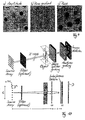
- the basis of the present invention is the two-grating interferometer as it is shown in figure 1 . It comprises the following components: an x-ray source XS (e.g. a stationary or rotating anode with a typical electron energy in the range of 10 to 100 keV, or any other X-ray source), an optional set of appropriate filters F, an object O, a beam splitter phase grating G1, an analyzer amplitude grating G2, and a spatially resolving x-ray detector D.
- the source XS provides some degree of spatial coherence at least in one direction perpendicular to the optical axis A.
- the anode material should be chosen to have appropriate lines in the energy range well suited for the specific application.
- these could be Nb, Mo, Rh, Pd, Ag, which have K-emission lines in the 15 to 25-keV region.
- the energy would be in the range of 5-10 keV (e.g. a Cu anode).
- the spectrum of the source XS may be filtered to reduce the source bandwidth.
- the beam splitter grating G1 with a period p 1 should be constructed such that it divides the incoming beam essentially into the two first diffraction orders.
- the conditions for this are that the grating lines have little absorption and shift the phase of the radiation passing through the grating lines by an odd multiple of n, and that the width of the phase-shifting structures is close to half of the grating period, i.e., that the grating has a duty cycle close to 0.5.
- the angle between the two diffracted beams is so small that they overlap almost completely.
- the diffracted beams interfere and form linear periodic fringe patterns in planes perpendicular to the optical axis A at a distance d downstream of G1 .
- the period of the interference fringes is about half of the period of G1. Neither the period nor the lateral position of these fringes depends on the wavelength of the radiation used. Perturbations of the incident wave front, such as those induced by refraction on a phase object in the beam, lead to local displacement of the fringes.
- a fundamental idea for the operation of the grating-based interferometer described here is to detect the positions of the fringes and determine from these the shape of the wave front.
- the periodicity of the phase grating does not exceed a few microns, an area detector placed in the detection plane will generally not have sufficient resolution to resolve the fringes, let alone the exact position of their maxima.
- an analyzer grating G2 with absorbing lines and the same periodicity p 2 and orientation as the fringes is placed in the detection plane, immediately before the detector.
- the transmission of the absorber lines should be as low as possible, and the width of the absorber lines should be close to the width of the gaps in between them (duty cycle close to 0.5) to give optimum performance.
- This analyzer grating G2 acts as a transmission mask for the detector D and transforms local fringe position into signal intensity variation.
- the detected intensity signal contains quantitative information about the phase shift induced by the object O. At least three methods can be applied to extract this phase information:
- Figure 5 shows processed radiographs a (x, y) and ⁇ (x,y) obtained by phase stepping, the integrated phase shift ⁇ (x,y) , as well as reconstructed tomograms of both the absorption and the phase signal and a three-dimensional rendering of the tomographically reconstructed refractive index of the sample, a small spider.
- the edge-enhanced absorption image a(x,y) shows strong contrast for fine details both in projection ( fig. 5a ) and tomogram ( fig. 5d ). But low spatial frequencies of the phase distribution are lost, so that image segmentation, i.e., the assignment of each pixel or voxel to one of the constituent materials of the sample, is not easily possible.
- phase tomogram ( fig. 5f ) exhibits a clear advantage: its pixel values are a direct measure of the decrement of refractive index ⁇ in the sample, and are therefore directly accessible to quantitative analysis. Moreover the edge enhancing inline Fresnel diffraction contrast in Figure 5a and d would not be observable at lower resolutions of the detector, whereas the interferometric phase contrast is not subject to such a limitation. This is of crucial importance when the interferometric method is scaled up to large fields of view, as the limited number of pixels will inherently limit the spatial resolution.
- the source can be moved either mechanically or by deflecting the electron beam of the x-ray source to move the position of the electron impact on the anode.
- the movement of the source point also has a larger component along the optical axis.
- the component perpendicular to the optical axis has an effect on the phase stepping.
- the total deflection of the beam on the anode surface is in this case larger reducing the requirements on the accuracy of the electron beam movement.
- a phase-stepping scan yields, for each pixel in the detector, a series of intensity values from which different quantities can be extracted, especially the phase ⁇ of the intensity oscillation in each pixel, which is related to the derivative of the wavefront phase ⁇ by eq. (2), and the average intensity a over an oscillation period, which essentially corresponds to the non-interferometric X-ray image.
- phase ⁇ of the intensity oscillation in each pixel which is related to the derivative of the wavefront phase ⁇ by eq. (2), and the average intensity a over an oscillation period, which essentially corresponds to the non-interferometric X-ray image.
- the range of the phase stepping scan should cover (at least) one period of the oscillation.
- the optical components are usually designed such that the contrast curve (as shown, e.g., in Fig. 4e ) is sinusoidal. In that case it is sufficient to take three points in a scan. The tangent of the phase ⁇ of the oscillation is then easily calculated by just taking the ratio of signal differences.
- the situation in the X-ray interferometer differs from the conventional one in that the shape of the contrast curve is not sinusoidal. (For the ideal case of box-profile gratings and fully coherent illumination, it would, for example, be triangular.) There are at least two ways to cope with this problem:
- the first method has the drawback of more necessary points per phase-stepping scan, but the advantage that higher Fourier components can potentially be used to extract additional information.
- the distance d between the two gratings can be chosen freely, although there are values of d for which the contrast is best and others for which it has a minimum (see below).
- the sensitivity of the method increases linearly with d .
- the choice of larger d may result in a loss of spatial resolution due to penumbral blurring, as the distance between the object and the detector is increased.
- a higher degree of lateral coherence is required (see below).
- the contrast of the interference fringes changes periodically as a function of d .
- any distance d n n p 1 2 / (8 ⁇ ) as the "n-th fractional Talbot distance” and to the planes at a distance d n from the phase grating as the " n -th fractional Talbot plane".
- d n 1, 3, 5, .
- l denotes the distance between the source and G1.
- phase shift of the lines of the grating G1 depends on the photon energy due to the dispersion of the grating material.
- the condition to induce a phase shift equal to odd multiples of n is not strict, and a radiation within a certain energy band in the order of ⁇ 10% around the design energy can be accepted.
- a deviation from n only affects the contrast - but it does not change the interference pattern qualitatively.
- the position of the Talbot planes depends on the photon energy.
- the refractive index of the object depends on the photon energy used. Nevertheless, reconstructed phase projections and tomograms will still be quantitative under the condition that the elements contained in the sample have no absorption edges in the range of the used photon energy band. In this case, all parts of the sample have the same dispersion relation, i.e. the real part of the refractive index changes with E -2 .
- phase shift induced by the structures of the grating G2 should be close to odd multiples of n and that the distance between the grating G1 and the grating G2 should be close to an odd fractional Talbot distance d n, sph .
- phase shift and fractional Talbot distance depend on the wavelength of the radiation used. It is therefore important that the grating structures and the distance chosen between the grating G1 and the grating G2 are matched to each other, meaning that both fulfill the conditions for the same wavelength. Moreover, it might be useful if this wavelength coincides with an emission line of the anode material of the used x-ray source. As mentioned above, the acceptable bandwidth is wide compared to other interferometric methods.
- emission lines e.g. the Cu-K ⁇ 1 , Cu-K ⁇ 2 and Cu-K ® - lines emitting at 8.048, 8.028 and 8.905 keV photon energy, or the Mo-K ⁇ 1 , Mo-K ⁇ 2 and Mo-K ® - lines emitting at 17.479, 17.374 and 19.608 keV photon energy, or the Ag-K ⁇ 1 , Ag-K ⁇ 2 and Ag-K ® - lines emitting at 22.163, 21.990 and 24.942 keV photon energy).
- emission lines e.g. the Cu-K ⁇ 1 , Cu-K ⁇ 2 and Cu-K ® - lines emitting at 8.048, 8.028 and 8.905 keV photon energy
- the setup described requires spatial coherence only in the direction perpendicular to the optical axis A and to the grating lines.
- t p 1 /2.
- the use of a smaller source will increase the spatial coherence, resulting in an improvement of the phase contrast.
- a line source can be used.
- the grating G2 comprises structures that are 5 to 10 microns thick - depending on the photon energy used -to provide sufficient x-ray absorption and that have, at the same time, widths on the order of one micron.
- the aspect ratio of the structures is therefore usually much greater than unity.
- the grating G2 can therefore also act as an anti-scatter grid.
- the anti-scatter grid of an x-ray imaging system may be used as the analyzer in a grating based interferometer, although this would require that the period of the anti-scatter grid be smaller than is the case in commonly available systems.
- the divergence angle of the x-ray beam is considerable, as the source cannot be placed at distances too far from the detector. Due to the high aspect ratio of the grating structures in the interferometer, especially of the grating G2, the beams in certain regions close to the edges of the field of view may pass through the gratings under too large angles. Only the angular component within the drawing of the lower part of figure 1 has an effect. To completely avoid this problem, the grating structures have to be bent or curved as depicted in Fig. 7a to d , or a scanning scheme with appropriate orientation of the gratings has to be applied.
- Fig. 7a illustrated a solution by bending the grating lines on a flat substrate.
- Fig. 7c schematically depicts the grating lines being placed on a curved surface.
- Fig. 7d shows a way that segments of a flat grating approximating the curved or bent geometry.
- a slit S placed between the source XS and the sample O generates a fan-shaped beam, and a one-dimensional line detector D 1 can be used, with its elements aligned to the fan.
- the two dimensional projection of the sample O is obtained by either scanning the sample through the fanbeam, or by scanning the beam across the sample and moving the line detector D 1 with the beam.
- the detector D 1 is read out at different positions during the scan and a two-dimensional image is created line by line.
- the scanning scheme has some important advantages compared to a two-dimensional setup: i) a suppression of diffuse scattering without an anti-scatter grid, since the slit S, together with the limited size of the source spot, acts as a collimator, ii) lower cost and higher detection efficiency of one-dimensional detectors in comparison with two-dimensional detectors.
- the grating based phase contrast can also be applied to a scanning scheme, as shown in Figure 8 . The advantage is that only gratings over a smaller area are required compared to a full-field imaging scheme, which will significantly reduce the cost.
- Figure 9 shows x-ray images of a test sample containing poly-methylmethacrylate (PMMA, 1.5 mm diameter) and Aluminum (1.0 mm diameter) spheres.
- the detector was a fiber-coupled CCD (model "Hystar", manufacturer Photonic Science) with an effective pixel size of approximately 30 ⁇ m. The data were acquired by phase stepping with 17 steps over 1 oscillation period, with an exposure time of 50 s for each CCD frame.
- the schema-tic setup of the proposed design is shown in Figure 10 .
- the difference to the previously described interferometer shown in Figure 1 is the x-ray source that consists of an array of N line sources.
- the line sources are oriented along the grating lines and the width of each source line is chosen narrow enough to provide sufficient spatial coherence in the direction perpendicular to the grating lines.
- each of the line sources is intrinsically coherent, whereas the lines can be mutually incoherent.
- the arrangement also works for source array periods that are integer multiples of p 0 .
- the size c of the source array can be much bigger than the width s of an individual line source.
- the duty cycle DC s / p 0 of the source array determines the degree of transverse coherence in the direction perpendicular to the interferometer grating lines.
- the interference patterns of all N virtual line sources add up incoherently (as the virtual line sources are mutually incoherent) but preserving contrast.
- the flux density is increased by a factor N compared to a single line source.
- a source array as described above can be obtained in various ways:
- Figure 12 shows images obtained under the similar conditions as those shown in figure 9 , i.e., with a laboratory X-ray source. The important difference is that this time a source with a size of 0.8 mm x 0.4 mm was used, which is far to large to provide sufficient transverse coherence for interferometric phase contrast.
- a source with a size of 0.8 mm x 0.4 mm was used, which is far to large to provide sufficient transverse coherence for interferometric phase contrast.
- phase contrast x-ray imaging configurations particularly suited for phase contrast x-ray imaging are listed in detail. They are designed for two different applications: desktop microtomography and mammography. The latter can be implemented either with a full-field setup or a scanning setup.
- a grating based interferometer for phase contrast desktop tomography system may consist of the following components:
- a grating based interferometer for a phase contrast full-field digital mammography (FFDM) system could consist of the following components:
- the source material, distances and grating periods can be chosen similar or identical to the FFDM example above.
- the following items would be different or additional with respect to the FFDM setup:
- phase grating is four times more efficient. Nonetheless, for a number of applications where these drawbacks can be tolerated and/or where a phase grating is not available, the use of an absorption grating as beam splitter can make sense.
Landscapes
- Health & Medical Sciences (AREA)
- Life Sciences & Earth Sciences (AREA)
- Engineering & Computer Science (AREA)
- Medical Informatics (AREA)
- Physics & Mathematics (AREA)
- Pathology (AREA)
- General Health & Medical Sciences (AREA)
- Nuclear Medicine, Radiotherapy & Molecular Imaging (AREA)
- Radiology & Medical Imaging (AREA)
- Heart & Thoracic Surgery (AREA)
- Veterinary Medicine (AREA)
- Biomedical Technology (AREA)
- High Energy & Nuclear Physics (AREA)
- Molecular Biology (AREA)
- Surgery (AREA)
- Animal Behavior & Ethology (AREA)
- Biophysics (AREA)
- Public Health (AREA)
- Optics & Photonics (AREA)
- Mathematical Physics (AREA)
- Chemical & Material Sciences (AREA)
- Analytical Chemistry (AREA)
- Biochemistry (AREA)
- General Physics & Mathematics (AREA)
- Immunology (AREA)
- Analysing Materials By The Use Of Radiation (AREA)
Claims (17)
- Interferometer für Röntgenstrahlen, insbesondere harte Röntgenstrahlen, zum Gewinnen quantitativer Phasenkontrastbilder, welches umfasst:a) eine standardmäßige polychromatische Röntgenstrahlenquelle,b) ein diffraktives optisches Element (G1), welches kein Bragg-Kristall ist, vorzugsweise in Transmissionsgeometrie, im Folgenden als ein Strahlteilergitter (G1) bezeichnet, undc) einen positionsempfindlichen Detektor (D) mit räumlich modulierter Detektionsempfindlichkeit,d) wobei die Röntgenstrahlenquelle eine ein- oder zweidimensionale Quellenanordnung von einzelnen physischen oder virtuellen Quellen umfasst, welche zueinander inkohärent sein können und deren seitliche Trennung p0 durch

dadurch gekennzeichnet, dasse) die ein- oder zweidimensionale Anordnung von Quellen erzeugt wird durch:i) Elektronenoptik, welche eine Anordnung von Elektronenlinien- oder Punktfokussen auf der Anode der Röntgenstrahlenquelle erzeugt, und/oderii) Elektronenoptik, welche einen einzelnen Linien- oder Punktfokus über die Anodenoberfläche der Röntgenstrahlenquelle scannt, und/oderiii) Verwendung einer Röntgenstrahlenquelle, die eine Anode umfasst, welche entweder topographisch strukturiert oder mosaikartig aus verschiedenen Materialien zusammengesetzt ist. - Interferometer nach Anspruch 1, wobei das Strahlteilergitter ein Liniengitter oder ein zweidimensional strukturiertes Gitter (G1) ist, vorzugsweise ein Phasengitter; das heißt ein Gitter mit geringer Röntgenstrahlenabsorption, jedoch beträchtlicher Röntgenstrahlen-Phasenverschiebung, wobei die Letztere vorzugsweise n oder ein ungeradzahliges Vielfaches davon beträgt.
- Interferometer nach Anspruch 1 oder 2, wobei das Strahlteilergitter durch Tiefätzen in Silizium oder ein Polymer hergestellt ist.
- Interferometer nach Anspruch 1, wobei ein Analysatorgitter (G2) nahe vor dem Detektor (D, D1) angeordnet ist, wobei das Analysatorgitter (G2) eine ein- oder zweidimensionale Gitterstruktur mit hohem Röntgenabsorptionskontrast ist; wobei diese Gitterstruktur vorzugsweise als ein Streustrahlenraster dient, oder ein Streustrahlenraster als eine Modulationsmaske verwendet wird.
- Interferometer nach Anspruch 1 oder 4, wobei das Analysatorgitter (G2) durch Abscheidung eines Schwermetalls in die Zwischenräume einer niedrig absorbierenden Struktur hergestellt wird.
- Interferometer nach Anspruch 1 oder Anspruch 2, wobei die Periode des Analysatorgitters (G2) und die Periode des Strahlteilers (G1) an den Krümmungsradius einer einfallenden Wellenfront angepasst sind durch die Beziehung

- Interferometer nach Anspruch 1 oder 2, wobei der Abstand zwischen dem Strahlteilergitter (G1) und dem Analysatorgitter (G2) so gewählt ist, dass er ein ungeradzahliger fraktionaler Talbot-Abstand ist, der durch die Gleichung

- Interferometer nach Anspruch 1 oder 2 oder 7, wobei die Phasenverschiebung des Strahlteilergitters (G1) und der Abstand zwischen dem Strahlteilergitter (G1) und dem Analysatorgitter (G2) an eine Photonenenergie angepasst sind, die einer Emissionslinie des Röntgenstrahlengenerators entspricht, der als die Quelle verwendet wird.
- Interferometer nach Anspruch 1, wobei ein Mechanismus enthalten ist, um die Winkelausrichtung, um die optische Achse, des Strahlteilergitters (G1) in Bezug auf das Analysatorgitter (G2) zu variieren, sodass entweder Moire-Streifen mit einer gewünschten Periode beobachtet werden können oder Moiré-Streifen minimiert oder vollständig unterdrückt werden können.
- Interferometer nach Anspruch 1, wobei ein ein- oder zweidimensionaler Phasenschritt-Scan (Phase-Stepping-Scan) durch seitliche Querbewegung der Strahlungsquelle oder einer vor der Strahlungsquelle angeordneten Apertur oder des Strahlteilergitters (G1) oder des Analysatorgitters (G2) oder durch eine Neigung des Interferometers in Bezug auf die Röntgenstrahlenquelle implementiert ist.
- Interferometer nach Anspruch 1, wobei ein Mechanismus enthalten ist, um eine zu untersuchende Probe (O) zwischen der Quelle (XS) und dem Strahlteilergitter (G1) oder zwischen dem Strahlteilergitter (G1) und der analysierenden Struktur, entweder dem Analysatorgitter (G2) oder dem positionsempfindlichen Detektor (D) mit räumlich modulierter Detektionsempfindlichkeit, anzuordnen.
- Interferometer nach Anspruch 1, wobei der Detektor (D) in zwei Dimensionen positionsempfindlich ist und die seitlichen Abmessungen des Strahlteilergitters (G1) und des Analysatorgitters (G2) einen wesentlichen Abschnitt der aktiven Fläche des Detektors (D) abdecken.
- Interferometer nach Anspruch 1, wobei ein Kollimator, der zwischen der Quelle und dem Strahlteilergitter (G1) angeordnet ist, die räumliche Ausdehnung der beleuchtenden Röntgenstrahlen auf einen Fächerstrahl begrenzt, ein Line-Array-Detektor verwendet wird und ein Mechanismus enthalten ist, welcher einen linearen Scan der Probe in Bezug auf den übrigen Teil der Vorrichtung ermöglicht, senkrecht zum Öffnungswinkel des Fächers.
- Interferometer nach Anspruch 1 oder 11, welches Mittel zum Drehen der Probe relativ zu den übrigen Komponenten umfasst, um ein Sammeln von Daten für einen Tomographie-Scan durchzuführen.
- Interferometer nach Anspruch 1 oder 10, wobei eine Analyseprozedur für Phasenschritt-Scan-Daten implementiert ist, welche die Schritte des Berechnens, für jedes Element des Detektors, der Fourier-Transformation oder wenigstens einer Fourier-Komponente der in dem Element gemessenen Intensitätskurve und des anschließenden Beibehaltens der Phase einer oder mehrerer Fourier-Komponenten als ein Signal für eine weitere Verarbeitung umfasst.
- Interferometer nach Anspruch 1 oder 10, wobei eine Analyseprozedur für Phasenschritt-Scan-Daten implementiert ist, welche die Schritte des Anpassens, für jedes Element des Detektors, der in dem Element gemessenen Intensitätskurve an eine Intensitätskurve, die separat ohne die zu untersuchenden Strahlverzerrungen modelliert oder gemessen wurde, umfasst, wobei mindestens einer der Anpassungsparameter die Verschiebung der Kurve entlang der Positionsachse des Scans ist.
- Interferometer nach einem der vorhergehenden Ansprüche, wobei das Strahlteilergitter ein Absorptionsgitter ist.
Priority Applications (1)
| Application Number | Priority Date | Filing Date | Title |
|---|---|---|---|
| EP06753957.7A EP1887936B1 (de) | 2005-06-06 | 2006-05-30 | Interferometer für die qantitative phasenkontrast-bilddarstellung und tomographie mit einer inkohärenten polychromatischen röntgenstrahlenquelle |
Applications Claiming Priority (3)
| Application Number | Priority Date | Filing Date | Title |
|---|---|---|---|
| EP05012121A EP1731099A1 (de) | 2005-06-06 | 2005-06-06 | Interferometer zur quantitativen Phasenkontrastbildgebung und -tomographie mit einer inkohärenten polychromatischen Röntgenquelle |
| EP06753957.7A EP1887936B1 (de) | 2005-06-06 | 2006-05-30 | Interferometer für die qantitative phasenkontrast-bilddarstellung und tomographie mit einer inkohärenten polychromatischen röntgenstrahlenquelle |
| PCT/EP2006/005119 WO2006131235A1 (en) | 2005-06-06 | 2006-05-30 | Interferometer for quantative phase contrast imaging and tomography with an incoherent polychromatic x-ray source |
Publications (2)
| Publication Number | Publication Date |
|---|---|
| EP1887936A1 EP1887936A1 (de) | 2008-02-20 |
| EP1887936B1 true EP1887936B1 (de) | 2013-12-25 |
Family
ID=35115941
Family Applications (2)
| Application Number | Title | Priority Date | Filing Date |
|---|---|---|---|
| EP05012121A Withdrawn EP1731099A1 (de) | 2005-06-06 | 2005-06-06 | Interferometer zur quantitativen Phasenkontrastbildgebung und -tomographie mit einer inkohärenten polychromatischen Röntgenquelle |
| EP06753957.7A Active EP1887936B1 (de) | 2005-06-06 | 2006-05-30 | Interferometer für die qantitative phasenkontrast-bilddarstellung und tomographie mit einer inkohärenten polychromatischen röntgenstrahlenquelle |
Family Applications Before (1)
| Application Number | Title | Priority Date | Filing Date |
|---|---|---|---|
| EP05012121A Withdrawn EP1731099A1 (de) | 2005-06-06 | 2005-06-06 | Interferometer zur quantitativen Phasenkontrastbildgebung und -tomographie mit einer inkohärenten polychromatischen Röntgenquelle |
Country Status (7)
| Country | Link |
|---|---|
| US (1) | US7889838B2 (de) |
| EP (2) | EP1731099A1 (de) |
| JP (1) | JP5162453B2 (de) |
| CN (1) | CN101257851B (de) |
| AU (1) | AU2006257026B2 (de) |
| CA (1) | CA2610934C (de) |
| WO (1) | WO2006131235A1 (de) |
Cited By (1)
| Publication number | Priority date | Publication date | Assignee | Title |
|---|---|---|---|---|
| US9949705B2 (en) | 2014-10-23 | 2018-04-24 | Siemens Aktiengesellschaft | Device and method for x-ray phase contrast imaging |
Families Citing this family (218)
| Publication number | Priority date | Publication date | Assignee | Title |
|---|---|---|---|---|
| DE102006017290B4 (de) * | 2006-02-01 | 2017-06-22 | Siemens Healthcare Gmbh | Fokus/Detektor-System einer Röntgenapparatur, Röntgen-System und Verfahren zur Erzeugung von Phasenkontrastaufnahmen |
| DE102006037256B4 (de) * | 2006-02-01 | 2017-03-30 | Paul Scherer Institut | Fokus-Detektor-Anordnung einer Röntgenapparatur zur Erzeugung projektiver oder tomographischer Phasenkontrastaufnahmen sowie Röntgensystem, Röntgen-C-Bogen-System und Röntgen-CT-System |
| DE102006063048B3 (de) * | 2006-02-01 | 2018-03-29 | Siemens Healthcare Gmbh | Fokus/Detektor-System einer Röntgenapparatur zur Erzeugung von Phasenkontrastaufnahmen |
| DE102006015358B4 (de) | 2006-02-01 | 2019-08-22 | Paul Scherer Institut | Fokus/Detektor-System einer Röntgenapparatur zur Erzeugung von Phasenkontrastaufnahmen, zugehöriges Röntgen-System sowie Speichermedium und Verfahren zur Erzeugung tomographischer Aufnahmen |
| WO2007100823A2 (en) * | 2006-02-27 | 2007-09-07 | University Of Rochester | Phase contrast cone-beam ct imaging |
| US8009889B2 (en) * | 2006-06-27 | 2011-08-30 | Affymetrix, Inc. | Feature intensity reconstruction of biological probe array |
| EP1879020A1 (de) * | 2006-07-12 | 2008-01-16 | Paul Scherrer Institut | Röntgenstrahlungsinterferometer für die Phasenkontrastbildgebung |
| JP2008145111A (ja) * | 2006-12-06 | 2008-06-26 | Univ Of Tokyo | X線撮像装置、これに用いるx線源、及び、x線撮像方法 |
| JP5056842B2 (ja) * | 2007-02-21 | 2012-10-24 | コニカミノルタエムジー株式会社 | 放射線画像撮影装置及び放射線画像撮影システム |
| WO2008102685A1 (ja) | 2007-02-21 | 2008-08-28 | Konica Minolta Medical & Graphic, Inc. | 放射線画像撮影装置及び放射線画像撮影システム |
| DE102007024156B3 (de) | 2007-05-24 | 2008-12-11 | Siemens Ag | Röntgenabsorptionsgitter |
| DE102007029730B4 (de) * | 2007-06-27 | 2017-06-08 | Paul Scherer Institut | Mess-System mit einem Phasenkontrast-Kontrastmittel und dessen Verwendung zur nicht-invasiven Bestimmung von Eigenschaften eines Untersuchungsobjektes |
| EP2060909B1 (de) * | 2007-11-15 | 2011-09-07 | CSEM Centre Suisse d'Electronique et de Microtechnique SA - Recherche et Développement | Interferometervorrichtung und Verfahren |
| EP2214558B1 (de) | 2007-11-26 | 2017-08-30 | Koninklijke Philips N.V. | Erkennungskonfiguration für eine röntgenphasenkontrastbildgebung |
| CN101467889B (zh) * | 2007-12-26 | 2010-08-25 | 中国科学院高能物理研究所 | 光栅剪切相位衬度ct成像数据采集和重建方法 |
| JP5158699B2 (ja) * | 2008-02-20 | 2013-03-06 | 国立大学法人 東京大学 | X線撮像装置、及び、これに用いるx線源 |
| CN101978257B (zh) * | 2008-03-19 | 2014-12-17 | 皇家飞利浦电子股份有限公司 | 用于相位衬度成像的旋转x射线装置 |
| JP2009240378A (ja) * | 2008-03-28 | 2009-10-22 | Univ Of Tokyo | X線撮像装置、及び、これに用いるスリット部材の製造方法 |
| US8809758B2 (en) * | 2008-07-25 | 2014-08-19 | Cornell University | Light field image sensor with an angle-sensitive pixel (ASP) device |
| US8530811B2 (en) * | 2008-07-25 | 2013-09-10 | Cornell University | Light field image sensor, method and applications |
| FR2935066A1 (fr) * | 2008-08-12 | 2010-02-19 | Chabunda Christophe Mwanza | Tube monoscopique produisant un faisceau de double des rayons x isospectraux |
| JP2010063646A (ja) * | 2008-09-11 | 2010-03-25 | Fujifilm Corp | 放射線位相画像撮影装置 |
| DE102008048688B4 (de) | 2008-09-24 | 2011-08-25 | Paul Scherrer Institut | Röntgen-CT-System zur Erzeugung tomographischer Phasenkontrast- oder Dunkelfeldaufnahmen |
| DE102008048683A1 (de) * | 2008-09-24 | 2010-04-08 | Siemens Aktiengesellschaft | Verfahren zur Bestimmung von Phase und/oder Amplitude zwischen interferierenden benachbarten Röntgenstrahlen in einem Detektorpixel bei einem Talbot-Interferometer |
| DE102008049200B4 (de) * | 2008-09-26 | 2010-11-11 | Paul Scherrer Institut | Verfahren zur Herstellung von röntgenoptischen Gittern, röntgenoptisches Gitter und Röntgen-System |
| EP2168488B1 (de) * | 2008-09-30 | 2013-02-13 | Siemens Aktiengesellschaft | Röntgen-CT-System zur Röntgen-Phasenkontrast-und/oder Röntgen-Dunkelfeld-Bildgebung |
| CN101413905B (zh) * | 2008-10-10 | 2011-03-16 | 深圳大学 | X射线微分干涉相衬成像系统 |
| JP4847568B2 (ja) * | 2008-10-24 | 2011-12-28 | キヤノン株式会社 | X線撮像装置およびx線撮像方法 |
| EP2343537B1 (de) * | 2008-10-29 | 2019-04-10 | Canon Kabushiki Kaisha | Röntgenbildgebungsvorrichtung und röntgenbildgebungsverfahren |
| BRPI0923198A2 (pt) * | 2008-12-01 | 2019-09-24 | Brookhaven Science Ass | sistemas e métodos para detecção de uma imagem de um objeto usando imagem multifeixe a partir de um feixe de raio x tendo tendo uma distribuição policromática |
| DK200801722A (en) * | 2008-12-05 | 2010-06-06 | Unisensor As | Optical sectioning of a sample and detection of particles in a sample |
| DE102009004702B4 (de) | 2009-01-15 | 2019-01-31 | Paul Scherer Institut | Anordnung und Verfahren zur projektiven und/oder tomographischen Phasenkontrastbildgebung mit Röntgenstrahlung |
| JP5606455B2 (ja) * | 2009-02-05 | 2014-10-15 | パウル・シェラー・インスティトゥート | 逆投影のためのイメージング装置及びその作動方法 |
| DE102009008793A1 (de) * | 2009-02-13 | 2010-11-11 | Inselspital-Stiftung | Verfahren zum Erzeugen einer Schichtbildaufnahme |
| US7949095B2 (en) | 2009-03-02 | 2011-05-24 | University Of Rochester | Methods and apparatus for differential phase-contrast fan beam CT, cone-beam CT and hybrid cone-beam CT |
| WO2010109912A1 (ja) * | 2009-03-27 | 2010-09-30 | 株式会社リガク | X線発生装置のターゲットと、その加工方法 |
| DE112010002512B4 (de) * | 2009-03-27 | 2024-03-14 | Rigaku Corp. | Röntgenstrahlerzeugungsvorrichtung und Untersuchungsvorrichtung, die diese verwendet |
| JP2010236986A (ja) * | 2009-03-31 | 2010-10-21 | Fujifilm Corp | 放射線位相画像撮影装置 |
| CN102395877B (zh) * | 2009-04-17 | 2014-04-09 | 西门子公司 | 用于进行相衬测量的检测装置和x射线断层摄影仪以及进行相衬测量的方法 |
| DE102009018882A1 (de) | 2009-04-24 | 2010-10-28 | Siemens Aktiengesellschaft | Elastographie-Verfahren und Vorrichtung |
| JP2010253194A (ja) * | 2009-04-28 | 2010-11-11 | Fujifilm Corp | 放射線位相画像撮影装置 |
| JP5587985B2 (ja) * | 2009-05-19 | 2014-09-10 | コーニンクレッカ フィリップス エヌ ヴェ | 位相コントラストイメージング用格子 |
| US8855265B2 (en) | 2009-06-16 | 2014-10-07 | Koninklijke Philips N.V. | Correction method for differential phase contrast imaging |
| CN102460237B (zh) | 2009-06-16 | 2015-04-15 | 皇家飞利浦电子股份有限公司 | 倾斜光栅和用于生产倾斜光栅的方法 |
| JP5675169B2 (ja) | 2009-06-18 | 2015-02-25 | キヤノン株式会社 | X線撮像装置およびx線撮像方法 |
| WO2010150136A1 (en) | 2009-06-22 | 2010-12-29 | Koninklijke Philips Electronics N. V. | Grating-based phase contrast x-ray imaging apparatus and methods |
| EP2478842A4 (de) * | 2009-09-16 | 2013-10-23 | Konica Minolta Med & Graphic | Röntgenbildgebungsvorrichtung, röntgenbildgebungssystem und röntgenbildgebungsverfahren |
| JP5459659B2 (ja) * | 2009-10-09 | 2014-04-02 | キヤノン株式会社 | X線位相コントラスト像の撮像に用いられる位相格子、該位相格子を用いた撮像装置、x線コンピューター断層撮影システム |
| JP5739902B2 (ja) | 2009-12-10 | 2015-06-24 | コーニンクレッカ フィリップス エヌ ヴェ | X線デバイス及び方法 |
| JP5789613B2 (ja) * | 2009-12-10 | 2015-10-07 | コーニンクレッカ フィリップス エヌ ヴェ | オンザフライ位相ステッピングを備えた非平行な格子装置、x線システム及び使用方法 |
| CN102655809B (zh) * | 2009-12-10 | 2015-06-17 | 皇家飞利浦电子股份有限公司 | 包括可位移x射线探测器元件的用于相称成像的设备和方法 |
| JP2013513418A (ja) * | 2009-12-10 | 2013-04-22 | コーニンクレッカ フィリップス エレクトロニクス エヌ ヴィ | 微分位相コントラストイメージングシステム |
| US9084528B2 (en) | 2009-12-10 | 2015-07-21 | Koninklijke Philips N.V. | Phase contrast imaging |
| JP5631013B2 (ja) * | 2010-01-28 | 2014-11-26 | キヤノン株式会社 | X線撮像装置 |
| JP5702586B2 (ja) * | 2010-02-04 | 2015-04-15 | 富士フイルム株式会社 | 放射線撮影システム |
| JP5538936B2 (ja) * | 2010-02-10 | 2014-07-02 | キヤノン株式会社 | 解析方法、プログラム、記憶媒体、x線位相イメージング装置 |
| JP2012090944A (ja) | 2010-03-30 | 2012-05-17 | Fujifilm Corp | 放射線撮影システム及び放射線撮影方法 |
| DE102010019991A1 (de) * | 2010-05-10 | 2011-11-10 | Siemens Aktiengesellschaft | Computertomographiesystem |
| JP5796976B2 (ja) * | 2010-05-27 | 2015-10-21 | キヤノン株式会社 | X線撮像装置 |
| DE102010017425A1 (de) * | 2010-06-17 | 2011-12-22 | Karlsruher Institut für Technologie | Geneigte Phasengitterstrukturen |
| WO2012000694A1 (en) * | 2010-06-28 | 2012-01-05 | Paul Scherrer Institut | A method for x-ray phase contrast and dark-field imaging using an arrangement of gratings in planar geometry |
| JP5646906B2 (ja) | 2010-08-06 | 2014-12-24 | キヤノン株式会社 | X線装置およびx線測定方法 |
| JP5731214B2 (ja) * | 2010-08-19 | 2015-06-10 | 富士フイルム株式会社 | 放射線撮影システム及びその画像処理方法 |
| US8995614B2 (en) * | 2010-09-29 | 2015-03-31 | Konica Minolta Medical & Graphic, Inc. | Method for displaying medical images and medical image display system |
| JP2012103237A (ja) * | 2010-10-14 | 2012-05-31 | Canon Inc | 撮像装置 |
| WO2012052881A1 (en) | 2010-10-19 | 2012-04-26 | Koninklijke Philips Electronics N.V. | Differential phase-contrast imaging |
| EP2630476B1 (de) | 2010-10-19 | 2017-12-13 | Koninklijke Philips N.V. | Differenzielle phasenkontrastbildgebung |
| JP5875280B2 (ja) * | 2010-10-20 | 2016-03-02 | キヤノン株式会社 | トールボット干渉を用いた撮像装置および撮像装置の調整方法 |
| WO2012056992A1 (ja) * | 2010-10-25 | 2012-05-03 | 富士フイルム株式会社 | 放射線画像検出装置、放射線撮影装置、放射線撮影システム |
| JP2014014380A (ja) * | 2010-10-28 | 2014-01-30 | Fujifilm Corp | 放射線撮影装置、及び放射線撮影システム |
| JP2012095865A (ja) * | 2010-11-02 | 2012-05-24 | Fujifilm Corp | 放射線撮影装置、放射線撮影システム |
| EP2652708B1 (de) * | 2010-12-13 | 2015-01-28 | Paul Scherrer Institut | Verfahren und system zur bildintegration mit eingeschränkter optimierung für phasenkontrastbildgebung mit einer anordnung aus gittern |
| JP5926281B2 (ja) * | 2010-12-13 | 2016-05-25 | コーニンクレッカ フィリップス エヌ ヴェKoninklijke Philips N.V. | X線を利用したオブジェクトの関心領域を解析するための方法及び装置 |
| JP5697430B2 (ja) * | 2010-12-17 | 2015-04-08 | キヤノン株式会社 | X線撮像装置 |
| JP2012143548A (ja) * | 2010-12-21 | 2012-08-02 | Fujifilm Corp | 放射線画像取得方法および放射線画像撮影装置 |
| JP2012130586A (ja) * | 2010-12-22 | 2012-07-12 | Fujifilm Corp | 放射線画像検出装置、放射線撮影装置、及び放射線撮影システム |
| JP2012157690A (ja) * | 2011-01-14 | 2012-08-23 | Fujifilm Corp | 放射線画像撮影装置および放射線画像検出器 |
| JP5792961B2 (ja) | 2011-01-25 | 2015-10-14 | キヤノン株式会社 | トールボット干渉計及び撮像方法 |
| JP5777360B2 (ja) * | 2011-03-14 | 2015-09-09 | キヤノン株式会社 | X線撮像装置 |
| EP2697858B1 (de) | 2011-04-14 | 2019-10-23 | Yale University | Verfahren zur bildgebung mithilfe eines zufallslasers |
| JP2014138625A (ja) * | 2011-04-25 | 2014-07-31 | Fujifilm Corp | 放射線撮影装置及び画像処理方法 |
| JP5787597B2 (ja) * | 2011-04-26 | 2015-09-30 | キヤノン株式会社 | 撮像装置 |
| BR112013028559A2 (pt) | 2011-05-09 | 2017-01-17 | Koninkl Philips Nv | aparelho para rotação de um objeto em uma tela, dispositivo, método para rotação de um objeto em uma tela, produto de programa de computador e meio para armazenagem |
| US20120307970A1 (en) * | 2011-05-31 | 2012-12-06 | General Electric Company | Multispot x-ray phase-contrast imaging system |
| US9557280B2 (en) | 2011-06-01 | 2017-01-31 | Total Sa | X-ray tomography device |
| BR112013030645A2 (pt) | 2011-06-01 | 2016-11-29 | Total Sa | dispositivo de tomografia de rios x |
| CN102353689B (zh) * | 2011-06-03 | 2013-05-08 | 中国科学院上海光学精密机械研究所 | 非相干x射线衍射成像装置 |
| WO2013010595A1 (en) * | 2011-07-19 | 2013-01-24 | Ovizio Imaging Systems N.V. | An object database and object database improving method |
| US9684281B2 (en) | 2011-07-19 | 2017-06-20 | Ovizio Imaging Systems NV/SA | Method and system for detecting and/or classifying cancerous cells in a cell sample |
| EP2594334A1 (de) | 2011-11-21 | 2013-05-22 | Drive O2 | Probenfläschchen zur digitalen holographischen Analyse einer flüssigen Zellprobe |
| JP6099645B2 (ja) * | 2011-07-28 | 2017-03-22 | パウル・シェラー・インスティトゥート | 主成分分析に基づく画像融合法およびx線用装置 |
| CA2843311C (en) | 2011-07-29 | 2016-06-07 | The Johns Hopkins University | Differential phase contrast x-ray imaging system and components |
| RU2598310C2 (ru) * | 2011-08-31 | 2016-09-20 | Конинклейке Филипс Н.В. | Формирование дифференциальных фазовых контрастных изображений с помощью чувствительного к энергии обнаружения |
| JP5475737B2 (ja) | 2011-10-04 | 2014-04-16 | 富士フイルム株式会社 | 放射線撮影装置及び画像処理方法 |
| US20150117599A1 (en) * | 2013-10-31 | 2015-04-30 | Sigray, Inc. | X-ray interferometric imaging system |
| JP2013116270A (ja) * | 2011-12-05 | 2013-06-13 | Canon Inc | X線撮像装置 |
| CN104066375B (zh) * | 2012-01-24 | 2017-08-11 | 皇家飞利浦有限公司 | 多方向相衬x射线成像 |
| EP2626686A1 (de) | 2012-02-13 | 2013-08-14 | Ovizio Imaging Systems NV/SA | Durchflusszytometer mit digitalem holografischen Mikroskop |
| WO2014137318A1 (en) * | 2012-03-05 | 2014-09-12 | University Of Rochester | Methods and apparatus for differential phase-contrast cone-beam ct and hybrid cone-beam ct |
| DE102012005767A1 (de) * | 2012-03-25 | 2013-09-26 | DüRR DENTAL AG | Phasenkontrast-Röntgen-Tomographiegerät |
| US20130259194A1 (en) * | 2012-03-30 | 2013-10-03 | Kwok L. Yip | Hybrid slot-scanning grating-based differential phase contrast imaging system for medical radiographic imaging |
| CN103364839B (zh) * | 2012-04-01 | 2015-12-09 | 中国科学院高能物理研究所 | 基于光栅剪切成像的安检设备及方法 |
| WO2013184213A2 (en) * | 2012-05-14 | 2013-12-12 | The General Hospital Corporation | A distributed, field emission-based x-ray source for phase contrast imaging |
| US9757081B2 (en) | 2012-06-27 | 2017-09-12 | Koninklijke Philips N.V. | Grating-based differential phase contrast imaging |
| DE102012213876A1 (de) | 2012-08-06 | 2014-02-06 | Siemens Aktiengesellschaft | Anordnung und Verfahren zur inversen Röntgen-Phasenkontrast-Bildgebung |
| WO2014027333A1 (en) | 2012-08-17 | 2014-02-20 | Koninklijke Philips N.V. | Correction in x-ray imaging systems for differential phase contrast imaging |
| WO2014027289A1 (en) | 2012-08-17 | 2014-02-20 | Koninklijke Philips N.V. | Handling misalignment in differential phase contrast imaging |
| JP6173457B2 (ja) * | 2012-08-20 | 2017-08-02 | コーニンクレッカ フィリップス エヌ ヴェKoninklijke Philips N.V. | 微分位相コントラスト撮像における複数オーダの位相調整のためのソース格子対位相格子距離の位置合わせ |
| KR101378757B1 (ko) * | 2012-08-30 | 2014-03-27 | 한국원자력연구원 | 물질 원소 정보 획득 및 영상 차원의 선택이 가능한 방사선 영상화 장치 |
| WO2014044823A1 (en) | 2012-09-20 | 2014-03-27 | Ovizio Imaging Systems NV/SA | Digital holographic microscope with fluid systems |
| JP6079204B2 (ja) * | 2012-12-18 | 2017-02-15 | コニカミノルタ株式会社 | 医用画像システム |
| TWI552727B (zh) * | 2012-12-19 | 2016-10-11 | 財團法人工業技術研究院 | 成像系統 |
| US9360439B2 (en) * | 2012-12-19 | 2016-06-07 | Industrial Technology Research Institute | Imaging system |
| US8989347B2 (en) | 2012-12-19 | 2015-03-24 | General Electric Company | Image reconstruction method for differential phase contrast X-ray imaging |
| CN104869905B (zh) * | 2012-12-21 | 2019-08-06 | 卡尔斯特里姆保健公司 | 基于微分相衬成像的医疗放射照相光栅 |
| US9494534B2 (en) | 2012-12-21 | 2016-11-15 | Carestream Health, Inc. | Material differentiation with phase contrast imaging |
| US9068927B2 (en) | 2012-12-21 | 2015-06-30 | General Electric Company | Laboratory diffraction-based phase contrast imaging technique |
| US9724063B2 (en) | 2012-12-21 | 2017-08-08 | Carestream Health, Inc. | Surrogate phantom for differential phase contrast imaging |
| US10578563B2 (en) | 2012-12-21 | 2020-03-03 | Carestream Health, Inc. | Phase contrast imaging computed tomography scanner |
| US9357975B2 (en) * | 2013-12-30 | 2016-06-07 | Carestream Health, Inc. | Large FOV phase contrast imaging based on detuned configuration including acquisition and reconstruction techniques |
| US9907524B2 (en) | 2012-12-21 | 2018-03-06 | Carestream Health, Inc. | Material decomposition technique using x-ray phase contrast imaging system |
| US10096098B2 (en) | 2013-12-30 | 2018-10-09 | Carestream Health, Inc. | Phase retrieval from differential phase contrast imaging |
| US9001967B2 (en) * | 2012-12-28 | 2015-04-07 | Carestream Health, Inc. | Spectral grating-based differential phase contrast system for medical radiographic imaging |
| US9700267B2 (en) | 2012-12-21 | 2017-07-11 | Carestream Health, Inc. | Method and apparatus for fabrication and tuning of grating-based differential phase contrast imaging system |
| US20140177789A1 (en) * | 2012-12-21 | 2014-06-26 | Pavlo Baturin | Grating-based differential phase contrast imaging system with adjustable capture technique for medical radiographic imaging |
| US9008278B2 (en) | 2012-12-28 | 2015-04-14 | General Electric Company | Multilayer X-ray source target with high thermal conductivity |
| US9014333B2 (en) | 2012-12-31 | 2015-04-21 | General Electric Company | Image reconstruction methods for differential phase contrast X-ray imaging |
| US9364191B2 (en) | 2013-02-11 | 2016-06-14 | University Of Rochester | Method and apparatus of spectral differential phase-contrast cone-beam CT and hybrid cone-beam CT |
| US9439613B2 (en) * | 2013-02-12 | 2016-09-13 | The Johns Hopkins University | System and method for phase-contrast X-ray imaging |
| JP6277204B2 (ja) | 2013-02-13 | 2018-02-07 | コーニンクレッカ フィリップス エヌ ヴェKoninklijke Philips N.V. | 多重x線ビーム管 |
| DE102013205406A1 (de) | 2013-03-27 | 2014-10-16 | Siemens Aktiengesellschaft | Röntgenaufnahmesystem zur Röntgenbildgebung bei hohen Bildfrequenzen eines Untersuchungsobjekts mittels direkter Messung des Interferenzmusters |
| EP3025365B1 (de) | 2013-07-23 | 2017-01-11 | Koninklijke Philips N.V. | Anode einer röntgenröhre einer differenzialphasenkontrastbildgebungsvorrichtung |
| US9297772B2 (en) | 2013-07-30 | 2016-03-29 | Industrial Technology Research Institute | Apparatus for amplifying intensity during transmission small angle—X-ray scattering measurements |
| US20150055745A1 (en) * | 2013-08-23 | 2015-02-26 | Carl Zeiss X-ray Microscopy, Inc. | Phase Contrast Imaging Using Patterned Illumination/Detector and Phase Mask |
| JP2015072263A (ja) * | 2013-09-09 | 2015-04-16 | キヤノン株式会社 | X線撮像システム |
| US10269528B2 (en) | 2013-09-19 | 2019-04-23 | Sigray, Inc. | Diverging X-ray sources using linear accumulation |
| US10295485B2 (en) | 2013-12-05 | 2019-05-21 | Sigray, Inc. | X-ray transmission spectrometer system |
| US10297359B2 (en) | 2013-09-19 | 2019-05-21 | Sigray, Inc. | X-ray illumination system with multiple target microstructures |
| DE102013219553A1 (de) | 2013-09-27 | 2015-04-02 | Friedrich-Alexander-Universität Erlangen-Nürnberg | Untersuchungsverfahren eines Objekts mit einem Röntgenaufnahmesystem zur Phasenkontrast-Bildgebung mit stochastischer Phasenabtastung |
| DE102013219554A1 (de) * | 2013-09-27 | 2015-04-02 | Friedrich-Alexander-Universität Erlangen-Nürnberg | Untersuchungsverfahren eines Objekts mit einem Röntgenaufnahmesystem zur Phasenkontrast-Bildgebung mit Verschiebungsmessung |
| CN104837409B (zh) * | 2013-09-30 | 2019-08-13 | 皇家飞利浦有限公司 | 具有可移动光栅的微分相位衬度成像装置 |
| WO2015052017A1 (de) | 2013-10-07 | 2015-04-16 | Siemens Aktiengesellschaft | Phasenkontrast-röntgenbildgebungsvorrichtung und phasengitter für eine solche |
| US9726622B2 (en) | 2013-10-31 | 2017-08-08 | Tohoku University | Non-destructive inspection device |
| USRE48612E1 (en) | 2013-10-31 | 2021-06-29 | Sigray, Inc. | X-ray interferometric imaging system |
| WO2015066333A1 (en) * | 2013-10-31 | 2015-05-07 | Sigray, Inc. | X-ray interferometric imaging system |
| US9719947B2 (en) * | 2013-10-31 | 2017-08-01 | Sigray, Inc. | X-ray interferometric imaging system |
| US10304580B2 (en) | 2013-10-31 | 2019-05-28 | Sigray, Inc. | Talbot X-ray microscope |
| CN104622492A (zh) * | 2013-11-11 | 2015-05-20 | 中国科学技术大学 | 一种x射线光栅相位衬度成像装置和方法 |
| CN105142524A (zh) * | 2014-02-10 | 2015-12-09 | 约翰斯·霍普金斯大学 | 处于高能量的x射线相衬成像和ct的大视场光栅干涉仪 |
| WO2015122542A1 (en) | 2014-02-14 | 2015-08-20 | Canon Kabushiki Kaisha | X-ray talbot interferometer and x-ray talbot interferometer system |
| DE102014203811B4 (de) * | 2014-03-03 | 2019-07-11 | Siemens Healthcare Gmbh | Ergänzungssystem zur interferometrischen Röntgenbildgebung und projektive Röntgenvorrichtung |
| JP2015166676A (ja) * | 2014-03-03 | 2015-09-24 | キヤノン株式会社 | X線撮像システム |
| JP6529984B2 (ja) * | 2014-05-01 | 2019-06-12 | シグレイ、インコーポレイテッド | X線干渉イメージングシステム |
| EP2942619A1 (de) * | 2014-05-07 | 2015-11-11 | Paul Scherrer Institut | Beugungsgitteransatz für Röntgengitterinterferometrie im Abtastmodus |
| US9746405B2 (en) | 2014-05-09 | 2017-08-29 | General Electric Company | Method for elementally detecting variations in density |
| US10401309B2 (en) | 2014-05-15 | 2019-09-03 | Sigray, Inc. | X-ray techniques using structured illumination |
| KR20170009909A (ko) * | 2014-05-15 | 2017-01-25 | 시그레이, 아이엔씨. | 주기적 구조의 측정과 특성화 및 분석을 위한 x-선 방법 |
| EP3143384B1 (de) * | 2014-05-15 | 2020-03-04 | Sigray Inc. | Röntgensystem und -verfahren zur messung, charakterisierung und analyse von periodischen strukturen |
| CN106575533B (zh) * | 2014-08-05 | 2018-11-27 | 皇家飞利浦有限公司 | 用于x射线成像设备的光栅设备 |
| JP6198989B2 (ja) | 2014-10-13 | 2017-09-20 | コーニンクレッカ フィリップス エヌ ヴェKoninklijke Philips N.V. | 動き得る物体の位相コントラスト及び/又は暗視野撮像のための格子装置 |
| CN105606633B (zh) * | 2014-11-04 | 2019-03-19 | 清华大学 | X射线相衬成像系统与成像方法 |
| EA028468B1 (ru) * | 2014-11-27 | 2017-11-30 | Федеральное государственное автономное образовательное учреждение высшего профессионального образования "Балтийский федеральный университет имени Иммануила Канта" | Способ определения оптических характеристик материалов на основе аномального преломления в рефракционных оптических элементах |
| EA030807B1 (ru) * | 2014-11-27 | 2018-09-28 | Федеральное государственное автономное образовательное учреждение высшего профессионального образования "Балтийский федеральный университет имени Иммануила Канта" | Способ определения оптических характеристик по интерференционной картине |
| US10117629B2 (en) | 2014-12-03 | 2018-11-06 | Board Of Supervisors Of Louisiana State University And Agricultural And Mechanical College | High energy grating techniques |
| CN104504710B (zh) * | 2014-12-30 | 2017-04-12 | 中国科学技术大学 | X射线光栅相位衬度成像中摩尔条纹的识别方法及装置 |
| JP6451400B2 (ja) * | 2015-02-26 | 2019-01-16 | コニカミノルタ株式会社 | 画像処理システム及び画像処理装置 |
| US10352880B2 (en) | 2015-04-29 | 2019-07-16 | Sigray, Inc. | Method and apparatus for x-ray microscopy |
| JP6626517B2 (ja) * | 2015-06-26 | 2019-12-25 | コーニンクレッカ フィリップス エヌ ヴェKoninklijke Philips N.V. | 暗視野および位相コントラストctのための堅牢な再構成 |
| DE102015213062A1 (de) * | 2015-07-13 | 2017-01-19 | Siemens Healthcare Gmbh | Verfahren zur Erzeugung einer differentiellen Röntgen-Phasenkontrast-Abbildung mit einer Talbot-Lau-Interferometer-Anordnung und Röntgen-Phasenkontrast-Vorrichtung |
| JP6604772B2 (ja) | 2015-08-05 | 2019-11-13 | キヤノン株式会社 | X線トールボット干渉計 |
| US10295486B2 (en) | 2015-08-18 | 2019-05-21 | Sigray, Inc. | Detector for X-rays with high spatial and high spectral resolution |
| EP3139156A1 (de) * | 2015-09-04 | 2017-03-08 | Paul Scherrer Institut | Zweiphasiges gitterinterferometer zur phasenkontrast-röntgenbildgebung |
| EP3349657B1 (de) | 2015-09-16 | 2019-06-05 | Koninklijke Philips N.V. | Durch dunkelfeld verstärkte virtuelle röntgenkolonoskopie |
| CN105590317B (zh) * | 2015-12-15 | 2018-12-28 | 中国计量科学研究院 | 一种图像高对比度分辨力客观评价方法及检测操作方法 |
| EP3196631A1 (de) | 2016-01-19 | 2017-07-26 | Ovizio Imaging Systems NV/SA | Digitales holografisches mikroskop mit elektrofluidischem system, besagtes elektrofluidisches system und verfahren zur verwendung |
| DE102016206153B4 (de) * | 2016-04-13 | 2023-04-27 | Siemens Healthcare Gmbh | Verfahren und Röntgensystem zur Erzeugung von Phasenkontrast- und/oder Dunkelfelddarstellungen eines Untersuchungsobjektes |
| CN107807139B (zh) * | 2016-09-05 | 2020-04-24 | 天津工业大学 | 一种无步进装置的双能x射线相衬成像系统及其实现方法 |
| US10247683B2 (en) | 2016-12-03 | 2019-04-02 | Sigray, Inc. | Material measurement techniques using multiple X-ray micro-beams |
| JP6673189B2 (ja) * | 2016-12-26 | 2020-03-25 | 株式会社島津製作所 | X線位相コントラスト撮影装置 |
| WO2018175570A1 (en) | 2017-03-22 | 2018-09-27 | Sigray, Inc. | Method of performing x-ray spectroscopy and x-ray absorption spectrometer system |
| EP3403581A1 (de) | 2017-05-15 | 2018-11-21 | Koninklijke Philips N.V. | Gittermontagevorrichtung differenzieller schlitz-scan-phasenkontrastbildgebung |
| CN107238616B (zh) * | 2017-06-22 | 2019-10-11 | 合肥工业大学 | 基于中子光栅干涉仪的暗场成像方法 |
| EP3443904A1 (de) * | 2017-08-14 | 2019-02-20 | Koninklijke Philips N.V. | Multifokale röntgenbildgebung |
| EP3450967A1 (de) * | 2017-09-01 | 2019-03-06 | Shimadzu Corporation | Röntgenbildgebungsvorrichtung |
| JP6838531B2 (ja) * | 2017-09-06 | 2021-03-03 | 株式会社島津製作所 | 放射線位相差撮影装置 |
| EP3459461A1 (de) | 2017-09-25 | 2019-03-27 | Koninklijke Philips N.V. | Röntgenbildgebungs-referenzabtastung |
| EP3527138B1 (de) * | 2018-01-30 | 2022-06-29 | Globus Medical, Inc. | Tragbares medizinisches bildgebungssystem mit strahlabtastung |
| JP6958716B2 (ja) * | 2018-03-01 | 2021-11-02 | 株式会社島津製作所 | X線位相差撮像システム |
| US10578566B2 (en) | 2018-04-03 | 2020-03-03 | Sigray, Inc. | X-ray emission spectrometer system |
| CN112424591B (zh) | 2018-06-04 | 2024-05-24 | 斯格瑞公司 | 波长色散x射线光谱仪 |
| DE112019003777B4 (de) | 2018-07-26 | 2025-09-11 | Sigray, Inc. | Röntgenreflexionsquelle mit hoher helligkeit |
| US10656105B2 (en) | 2018-08-06 | 2020-05-19 | Sigray, Inc. | Talbot-lau x-ray source and interferometric system |
| CN112638261B (zh) | 2018-09-04 | 2025-06-27 | 斯格瑞公司 | 利用滤波的x射线荧光的系统和方法 |
| US11056308B2 (en) | 2018-09-07 | 2021-07-06 | Sigray, Inc. | System and method for depth-selectable x-ray analysis |
| CN109580667B (zh) * | 2018-12-05 | 2020-10-27 | 中国科学技术大学 | 单光栅相衬成像方法及系统 |
| CN111721786B (zh) * | 2019-03-22 | 2023-05-26 | 中国科学院深圳先进技术研究院 | 一种x射线干涉仪及成像系统 |
| CN110133011B (zh) * | 2019-05-28 | 2022-04-15 | 中国科学院苏州生物医学工程技术研究所 | 免步进x射线光栅相衬成像方法 |
| JP7180562B2 (ja) * | 2019-07-18 | 2022-11-30 | 株式会社島津製作所 | X線位相撮像装置 |
| JP7182749B2 (ja) | 2019-09-03 | 2022-12-02 | シグレイ、インコーポレイテッド | コンピュータ断層撮影蛍光x線撮像のためのシステムおよび方法 |
| CN110989313B (zh) * | 2019-11-18 | 2021-10-01 | 中国科学技术大学 | 全息显微成像装置 |
| US11175243B1 (en) | 2020-02-06 | 2021-11-16 | Sigray, Inc. | X-ray dark-field in-line inspection for semiconductor samples |
| WO2021237237A1 (en) | 2020-05-18 | 2021-11-25 | Sigray, Inc. | System and method for x-ray absorption spectroscopy using a crystal analyzer and a plurality of detector elements |
| JP7460577B2 (ja) | 2020-06-03 | 2024-04-02 | 株式会社リガク | X線画像生成装置 |
| WO2022061347A1 (en) | 2020-09-17 | 2022-03-24 | Sigray, Inc. | System and method using x-rays for depth-resolving metrology and analysis |
| US12480892B2 (en) | 2020-12-07 | 2025-11-25 | Sigray, Inc. | High throughput 3D x-ray imaging system using a transmission x-ray source |
| KR20260030946A (ko) | 2020-12-07 | 2026-03-06 | 시그레이, 아이엔씨. | 투과 x-선 소스를 이용한 고처리량 3D x-선 이미징 시스템 |
| EP4020024A1 (de) | 2020-12-22 | 2022-06-29 | Paul Scherrer Institut | Verfahren zur herstellung einer fächerförmigen optik mit hohem aspektverhältnis |
| US11813102B2 (en) * | 2021-10-06 | 2023-11-14 | Houxun Miao | Interferometer for x-ray phase contrast imaging |
| WO2023168204A1 (en) | 2022-03-02 | 2023-09-07 | Sigray, Inc. | X-ray fluorescence system and x-ray source with electrically insulative target material |
| US11992350B2 (en) | 2022-03-15 | 2024-05-28 | Sigray, Inc. | System and method for compact laminography utilizing microfocus transmission x-ray source and variable magnification x-ray detector |
| WO2023215204A1 (en) | 2022-05-02 | 2023-11-09 | Sigray, Inc. | X-ray sequential array wavelength dispersive spectrometer |
| CN115172122B (zh) * | 2022-07-29 | 2025-08-12 | 西安交通大学 | 用于准单轴分幅及多轴同步x射线闪光照相的负载构型 |
| DE112024000873T5 (de) | 2023-02-16 | 2026-01-15 | Sigray, Inc. | Röntgen-detektorsystem mit mindestens zwei gestapelten flachen bragg-diffraktoren |
| US12181423B1 (en) | 2023-09-07 | 2024-12-31 | Sigray, Inc. | Secondary image removal using high resolution x-ray transmission sources |
| US12429437B2 (en) | 2023-11-07 | 2025-09-30 | Sigray, Inc. | System and method for x-ray absorption spectroscopy using spectral information from two orthogonal planes |
| WO2025151383A1 (en) | 2024-01-08 | 2025-07-17 | Sigray, Inc. | X-ray analysis system with focused x-ray beam and non-x-ray microscope |
| WO2025155719A1 (en) | 2024-01-18 | 2025-07-24 | Sigray, Inc. | Sequential array of x-ray imaging detectors |
| WO2025174966A1 (en) | 2024-02-15 | 2025-08-21 | Sigray, Inc. | System and method for generating a focused x‑ray beam |
Family Cites Families (4)
| Publication number | Priority date | Publication date | Assignee | Title |
|---|---|---|---|---|
| US5812629A (en) * | 1997-04-30 | 1998-09-22 | Clauser; John F. | Ultrahigh resolution interferometric x-ray imaging |
| EP1623671A4 (de) | 2002-12-26 | 2008-11-05 | Atsushi Momose | Röntgendarstellungssystem und darstellungsverfahren |
| EP1447046A1 (de) * | 2003-02-14 | 2004-08-18 | Paul Scherrer Institut | Vorrichtung und Verfahren zur Aufnahme von Phasenkontrast-Röntgenbildern |
| CN1560613A (zh) * | 2004-03-04 | 2005-01-05 | 中国科学院上海光学精密机械研究所 | X射线相衬位相差放大成像装置 |
-
2005
- 2005-06-06 EP EP05012121A patent/EP1731099A1/de not_active Withdrawn
-
2006
- 2006-05-30 JP JP2008515098A patent/JP5162453B2/ja active Active
- 2006-05-30 CA CA2610934A patent/CA2610934C/en not_active Expired - Fee Related
- 2006-05-30 AU AU2006257026A patent/AU2006257026B2/en not_active Ceased
- 2006-05-30 CN CN2006800294348A patent/CN101257851B/zh active Active
- 2006-05-30 EP EP06753957.7A patent/EP1887936B1/de active Active
- 2006-05-30 US US11/921,709 patent/US7889838B2/en active Active
- 2006-05-30 WO PCT/EP2006/005119 patent/WO2006131235A1/en not_active Ceased
Cited By (1)
| Publication number | Priority date | Publication date | Assignee | Title |
|---|---|---|---|---|
| US9949705B2 (en) | 2014-10-23 | 2018-04-24 | Siemens Aktiengesellschaft | Device and method for x-ray phase contrast imaging |
Also Published As
| Publication number | Publication date |
|---|---|
| AU2006257026A1 (en) | 2006-12-14 |
| CA2610934C (en) | 2014-09-30 |
| US20090092227A1 (en) | 2009-04-09 |
| CA2610934A1 (en) | 2006-12-14 |
| EP1887936A1 (de) | 2008-02-20 |
| CN101257851B (zh) | 2011-06-15 |
| JP2008545981A (ja) | 2008-12-18 |
| CN101257851A (zh) | 2008-09-03 |
| WO2006131235A1 (en) | 2006-12-14 |
| JP5162453B2 (ja) | 2013-03-13 |
| US7889838B2 (en) | 2011-02-15 |
| EP1731099A1 (de) | 2006-12-13 |
| AU2006257026B2 (en) | 2010-03-04 |
Similar Documents
| Publication | Publication Date | Title |
|---|---|---|
| US7889838B2 (en) | Interferometer for quantitative phase contrast imaging and tomography with an incoherent polychromatic x-ray source | |
| JP6177306B2 (ja) | 医療用放射線撮像のためのハイブリッドpciシステム | |
| US10058300B2 (en) | Large FOV phase contrast imaging based on detuned configuration including acquisition and reconstruction techniques | |
| JP5601909B2 (ja) | X線撮像装置及びこれを用いるx線撮像方法 | |
| Momose et al. | Phase tomography by X-ray Talbot interferometry for biological imaging | |
| US7639786B2 (en) | X-ray optical transmission grating of a focus-detector arrangement of an X-ray apparatus for generating projective or tomographic phase contrast recordings of a subject | |
| US7564941B2 (en) | Focus-detector arrangement for generating projective or tomographic phase contrast recordings with X-ray optical gratings | |
| EP2510522B1 (de) | Nicht-parallele rasteranordnung mit on-the-fly-phasenschritt und röntgensystem | |
| EP2509503B1 (de) | Vorrichtung für phasenkontrastbildgebung mit einem verschiebbaren röntgendetektorelement und verfahren | |
| EP3956692B1 (de) | In-line-röntgenfokussierungsoptik zur manipulation von röntgenstrahlen in der medizinischen transmissionsradiografie | |
| WO2007125833A1 (ja) | X線撮像装置及びx線撮像方法 | |
| WO2009076700A1 (en) | Phase-contrast imaging method and apparatus | |
| JP5455931B2 (ja) | 線状照射線源および焦点合わせ光学器を用いたシュリーレン式ラジオグラフィー | |
| JP2009195349A (ja) | X線撮像装置、及び、これに用いるx線源 | |
| EP2671230B1 (de) | Differentielle phasenkontrastbildgebung mit fokussierungsablenkstrukturplatten | |
| CN103575750A (zh) | 用于反向的x射线-相位对比成像的装置和方法 | |
| WO2010150136A1 (en) | Grating-based phase contrast x-ray imaging apparatus and methods | |
| Viermetz et al. | Technical design considerations of a human-scale Talbot-Lau interferometer for dark-field CT | |
| Akihisa Takeuchi et al. | Hard X-ray microtomography using X-ray imaging optics | |
| Kagoshima et al. | A New Apparatus for Hard X‐Ray Micro‐Imaging and Microdiffraction Experiments at BL24XU of SPring‐8 | |
| JP2020038153A (ja) | 放射線画像生成装置 | |
| Viermetz et al. | Dark-Field for Human CT–Realization of a Talbot-Lau Interferometer in a Clinical CT Gantry |
Legal Events
| Date | Code | Title | Description |
|---|---|---|---|
| PUAI | Public reference made under article 153(3) epc to a published international application that has entered the european phase |
Free format text: ORIGINAL CODE: 0009012 |
|
| 17P | Request for examination filed |
Effective date: 20071126 |
|
| RBV | Designated contracting states (corrected) |
Designated state(s): AT BE BG CH CY CZ DE DK EE ES FI FR GB GR HU IE IS IT LI LT LU LV MC NL PL PT RO SE SI SK TR |
|
| DAX | Request for extension of the european patent (deleted) | ||
| 17Q | First examination report despatched |
Effective date: 20071127 |
|
| GRAP | Despatch of communication of intention to grant a patent |
Free format text: ORIGINAL CODE: EPIDOSNIGR1 |
|
| GRAS | Grant fee paid |
Free format text: ORIGINAL CODE: EPIDOSNIGR3 |
|
| GRAA | (expected) grant |
Free format text: ORIGINAL CODE: 0009210 |
|
| AK | Designated contracting states |
Kind code of ref document: B1 Designated state(s): AT BE BG CH CY CZ DE DK EE ES FI FR GB GR HU IE IS IT LI LT LU LV MC NL PL PT RO SE SI SK TR |
|
| REG | Reference to a national code |
Ref country code: GB Ref legal event code: FG4D |
|
| REG | Reference to a national code |
Ref country code: CH Ref legal event code: NV Representative=s name: SIEMENS SCHWEIZ AG, CH Ref country code: CH Ref legal event code: EP |
|
| REG | Reference to a national code |
Ref country code: AT Ref legal event code: REF Ref document number: 646124 Country of ref document: AT Kind code of ref document: T Effective date: 20140115 |
|
| REG | Reference to a national code |
Ref country code: IE Ref legal event code: FG4D |
|
| REG | Reference to a national code |
Ref country code: DE Ref legal event code: R096 Ref document number: 602006039786 Country of ref document: DE Effective date: 20140213 |
|
| REG | Reference to a national code |
Ref country code: NL Ref legal event code: T3 |
|
| PG25 | Lapsed in a contracting state [announced via postgrant information from national office to epo] |
Ref country code: LT Free format text: LAPSE BECAUSE OF FAILURE TO SUBMIT A TRANSLATION OF THE DESCRIPTION OR TO PAY THE FEE WITHIN THE PRESCRIBED TIME-LIMIT Effective date: 20131225 Ref country code: FI Free format text: LAPSE BECAUSE OF FAILURE TO SUBMIT A TRANSLATION OF THE DESCRIPTION OR TO PAY THE FEE WITHIN THE PRESCRIBED TIME-LIMIT Effective date: 20131225 Ref country code: SE Free format text: LAPSE BECAUSE OF FAILURE TO SUBMIT A TRANSLATION OF THE DESCRIPTION OR TO PAY THE FEE WITHIN THE PRESCRIBED TIME-LIMIT Effective date: 20131225 |
|
| REG | Reference to a national code |
Ref country code: LT Ref legal event code: MG4D |
|
| PG25 | Lapsed in a contracting state [announced via postgrant information from national office to epo] |
Ref country code: LV Free format text: LAPSE BECAUSE OF FAILURE TO SUBMIT A TRANSLATION OF THE DESCRIPTION OR TO PAY THE FEE WITHIN THE PRESCRIBED TIME-LIMIT Effective date: 20131225 |
|
| PG25 | Lapsed in a contracting state [announced via postgrant information from national office to epo] |
Ref country code: IS Free format text: LAPSE BECAUSE OF FAILURE TO SUBMIT A TRANSLATION OF THE DESCRIPTION OR TO PAY THE FEE WITHIN THE PRESCRIBED TIME-LIMIT Effective date: 20140425 Ref country code: EE Free format text: LAPSE BECAUSE OF FAILURE TO SUBMIT A TRANSLATION OF THE DESCRIPTION OR TO PAY THE FEE WITHIN THE PRESCRIBED TIME-LIMIT Effective date: 20131225 |
|
| PG25 | Lapsed in a contracting state [announced via postgrant information from national office to epo] |
Ref country code: CY Free format text: LAPSE BECAUSE OF FAILURE TO SUBMIT A TRANSLATION OF THE DESCRIPTION OR TO PAY THE FEE WITHIN THE PRESCRIBED TIME-LIMIT Effective date: 20131225 Ref country code: PL Free format text: LAPSE BECAUSE OF FAILURE TO SUBMIT A TRANSLATION OF THE DESCRIPTION OR TO PAY THE FEE WITHIN THE PRESCRIBED TIME-LIMIT Effective date: 20131225 Ref country code: CZ Free format text: LAPSE BECAUSE OF FAILURE TO SUBMIT A TRANSLATION OF THE DESCRIPTION OR TO PAY THE FEE WITHIN THE PRESCRIBED TIME-LIMIT Effective date: 20131225 Ref country code: RO Free format text: LAPSE BECAUSE OF FAILURE TO SUBMIT A TRANSLATION OF THE DESCRIPTION OR TO PAY THE FEE WITHIN THE PRESCRIBED TIME-LIMIT Effective date: 20131225 Ref country code: SK Free format text: LAPSE BECAUSE OF FAILURE TO SUBMIT A TRANSLATION OF THE DESCRIPTION OR TO PAY THE FEE WITHIN THE PRESCRIBED TIME-LIMIT Effective date: 20131225 |
|
| REG | Reference to a national code |
Ref country code: DE Ref legal event code: R097 Ref document number: 602006039786 Country of ref document: DE |
|
| PG25 | Lapsed in a contracting state [announced via postgrant information from national office to epo] |
Ref country code: DK Free format text: LAPSE BECAUSE OF FAILURE TO SUBMIT A TRANSLATION OF THE DESCRIPTION OR TO PAY THE FEE WITHIN THE PRESCRIBED TIME-LIMIT Effective date: 20131225 |
|
| PLBE | No opposition filed within time limit |
Free format text: ORIGINAL CODE: 0009261 |
|
| STAA | Information on the status of an ep patent application or granted ep patent |
Free format text: STATUS: NO OPPOSITION FILED WITHIN TIME LIMIT |
|
| 26N | No opposition filed |
Effective date: 20140926 |
|
| PG25 | Lapsed in a contracting state [announced via postgrant information from national office to epo] |
Ref country code: LU Free format text: LAPSE BECAUSE OF FAILURE TO SUBMIT A TRANSLATION OF THE DESCRIPTION OR TO PAY THE FEE WITHIN THE PRESCRIBED TIME-LIMIT Effective date: 20140530 |
|
| REG | Reference to a national code |
Ref country code: DE Ref legal event code: R097 Ref document number: 602006039786 Country of ref document: DE Effective date: 20140926 |
|
| PG25 | Lapsed in a contracting state [announced via postgrant information from national office to epo] |
Ref country code: MC Free format text: LAPSE BECAUSE OF FAILURE TO SUBMIT A TRANSLATION OF THE DESCRIPTION OR TO PAY THE FEE WITHIN THE PRESCRIBED TIME-LIMIT Effective date: 20131225 |
|
| REG | Reference to a national code |
Ref country code: IE Ref legal event code: MM4A |
|
| PG25 | Lapsed in a contracting state [announced via postgrant information from national office to epo] |
Ref country code: IE Free format text: LAPSE BECAUSE OF NON-PAYMENT OF DUE FEES Effective date: 20140530 |
|
| PG25 | Lapsed in a contracting state [announced via postgrant information from national office to epo] |
Ref country code: SI Free format text: LAPSE BECAUSE OF FAILURE TO SUBMIT A TRANSLATION OF THE DESCRIPTION OR TO PAY THE FEE WITHIN THE PRESCRIBED TIME-LIMIT Effective date: 20131225 |
|
| REG | Reference to a national code |
Ref country code: FR Ref legal event code: PLFP Year of fee payment: 11 |
|
| PG25 | Lapsed in a contracting state [announced via postgrant information from national office to epo] |
Ref country code: BG Free format text: LAPSE BECAUSE OF FAILURE TO SUBMIT A TRANSLATION OF THE DESCRIPTION OR TO PAY THE FEE WITHIN THE PRESCRIBED TIME-LIMIT Effective date: 20131225 |
|
| PG25 | Lapsed in a contracting state [announced via postgrant information from national office to epo] |
Ref country code: GR Free format text: LAPSE BECAUSE OF FAILURE TO SUBMIT A TRANSLATION OF THE DESCRIPTION OR TO PAY THE FEE WITHIN THE PRESCRIBED TIME-LIMIT Effective date: 20140326 Ref country code: PT Free format text: LAPSE BECAUSE OF FAILURE TO SUBMIT A TRANSLATION OF THE DESCRIPTION OR TO PAY THE FEE WITHIN THE PRESCRIBED TIME-LIMIT Effective date: 20131225 |
|
| PG25 | Lapsed in a contracting state [announced via postgrant information from national office to epo] |
Ref country code: HU Free format text: LAPSE BECAUSE OF FAILURE TO SUBMIT A TRANSLATION OF THE DESCRIPTION OR TO PAY THE FEE WITHIN THE PRESCRIBED TIME-LIMIT; INVALID AB INITIO Effective date: 20060530 Ref country code: TR Free format text: LAPSE BECAUSE OF FAILURE TO SUBMIT A TRANSLATION OF THE DESCRIPTION OR TO PAY THE FEE WITHIN THE PRESCRIBED TIME-LIMIT Effective date: 20131225 |
|
| PG25 | Lapsed in a contracting state [announced via postgrant information from national office to epo] |
Ref country code: ES Free format text: LAPSE BECAUSE OF FAILURE TO SUBMIT A TRANSLATION OF THE DESCRIPTION OR TO PAY THE FEE WITHIN THE PRESCRIBED TIME-LIMIT Effective date: 20131225 |
|
| REG | Reference to a national code |
Ref country code: FR Ref legal event code: PLFP Year of fee payment: 12 |
|
| REG | Reference to a national code |
Ref country code: FR Ref legal event code: PLFP Year of fee payment: 13 |
|
| PGFP | Annual fee paid to national office [announced via postgrant information from national office to epo] |
Ref country code: NL Payment date: 20210504 Year of fee payment: 16 Ref country code: IT Payment date: 20210525 Year of fee payment: 16 |
|
| PGFP | Annual fee paid to national office [announced via postgrant information from national office to epo] |
Ref country code: BE Payment date: 20210519 Year of fee payment: 16 Ref country code: AT Payment date: 20210412 Year of fee payment: 16 |
|
| REG | Reference to a national code |
Ref country code: NL Ref legal event code: MM Effective date: 20220601 |
|
| REG | Reference to a national code |
Ref country code: AT Ref legal event code: MM01 Ref document number: 646124 Country of ref document: AT Kind code of ref document: T Effective date: 20220530 |
|
| REG | Reference to a national code |
Ref country code: BE Ref legal event code: MM Effective date: 20220531 |
|
| PG25 | Lapsed in a contracting state [announced via postgrant information from national office to epo] |
Ref country code: AT Free format text: LAPSE BECAUSE OF NON-PAYMENT OF DUE FEES Effective date: 20220530 |
|
| PG25 | Lapsed in a contracting state [announced via postgrant information from national office to epo] |
Ref country code: BE Free format text: LAPSE BECAUSE OF NON-PAYMENT OF DUE FEES Effective date: 20220531 |
|
| PG25 | Lapsed in a contracting state [announced via postgrant information from national office to epo] |
Ref country code: NL Free format text: LAPSE BECAUSE OF NON-PAYMENT OF DUE FEES Effective date: 20220601 |
|
| PG25 | Lapsed in a contracting state [announced via postgrant information from national office to epo] |
Ref country code: IT Free format text: LAPSE BECAUSE OF NON-PAYMENT OF DUE FEES Effective date: 20220530 |
|
| PGFP | Annual fee paid to national office [announced via postgrant information from national office to epo] |
Ref country code: GB Payment date: 20250610 Year of fee payment: 20 |
|
| PGFP | Annual fee paid to national office [announced via postgrant information from national office to epo] |
Ref country code: FR Payment date: 20250516 Year of fee payment: 20 |
|
| PGFP | Annual fee paid to national office [announced via postgrant information from national office to epo] |
Ref country code: DE Payment date: 20250718 Year of fee payment: 20 |
|
| PGFP | Annual fee paid to national office [announced via postgrant information from national office to epo] |
Ref country code: CH Payment date: 20250812 Year of fee payment: 20 |