EP1887286B1 - Verbesserungen an der Entlüftungsanordnung einer Rauchabzugshaube - Google Patents
Verbesserungen an der Entlüftungsanordnung einer Rauchabzugshaube Download PDFInfo
- Publication number
- EP1887286B1 EP1887286B1 EP20070113229 EP07113229A EP1887286B1 EP 1887286 B1 EP1887286 B1 EP 1887286B1 EP 20070113229 EP20070113229 EP 20070113229 EP 07113229 A EP07113229 A EP 07113229A EP 1887286 B1 EP1887286 B1 EP 1887286B1
- Authority
- EP
- European Patent Office
- Prior art keywords
- extractor hood
- hood according
- cylindrical member
- air
- suction
- Prior art date
- Legal status (The legal status is an assumption and is not a legal conclusion. Google has not performed a legal analysis and makes no representation as to the accuracy of the status listed.)
- Not-in-force
Links
- 239000003517 fume Substances 0.000 title claims description 14
- 238000009423 ventilation Methods 0.000 title claims description 7
- 238000000605 extraction Methods 0.000 title description 6
- 238000010411 cooking Methods 0.000 claims description 21
- 239000007789 gas Substances 0.000 claims description 19
- 238000001914 filtration Methods 0.000 claims description 2
- 230000001360 synchronised effect Effects 0.000 claims description 2
- 238000009830 intercalation Methods 0.000 claims 1
- 239000000203 mixture Substances 0.000 claims 1
- 230000002093 peripheral effect Effects 0.000 claims 1
- 230000000694 effects Effects 0.000 description 9
- 238000002474 experimental method Methods 0.000 description 7
- 238000010276 construction Methods 0.000 description 3
- 238000009434 installation Methods 0.000 description 3
- 230000002452 interceptive effect Effects 0.000 description 3
- 238000000034 method Methods 0.000 description 3
- 238000007664 blowing Methods 0.000 description 1
- 230000001427 coherent effect Effects 0.000 description 1
- 230000002708 enhancing effect Effects 0.000 description 1
- 238000011835 investigation Methods 0.000 description 1
- 238000007619 statistical method Methods 0.000 description 1
- 239000002341 toxic gas Substances 0.000 description 1
Images








Classifications
-
- F—MECHANICAL ENGINEERING; LIGHTING; HEATING; WEAPONS; BLASTING
- F24—HEATING; RANGES; VENTILATING
- F24C—DOMESTIC STOVES OR RANGES ; DETAILS OF DOMESTIC STOVES OR RANGES, OF GENERAL APPLICATION
- F24C15/00—Details
- F24C15/20—Removing cooking fumes
Definitions
- the present invention refers to an improved kind of extractor hood for extracting fumes and vapours from a closed room and exhausting them outside, as provided with improved means adapted to perform the task of conveying and exhausting said fumes and vapours in a particularly quick, efficient and cost-effective manner.
- JP 02-183750 is an extractor hood that generates a vortex, which is generally of assistance to the circulation and the exhaustion of the gases being extracted; such vortex is brought about by at least a blowing port located vertically and laterally relative to the same hood.
- JP 01-114650 is an extractor hood that is provided on its lower side with a circular member having appropriate perforations distributed all over it, from which related air flows are ejected so as to bring about a whirling, i.e. vortex-like circulation inside them and, as a result, even in the space therebelow.
- a circular member having appropriate perforations distributed all over it, from which related air flows are ejected so as to bring about a whirling, i.e. vortex-like circulation inside them and, as a result, even in the space therebelow.
- Such circular member is capable of being oriented and located exactly in the preferred position above the burner or hotplate generating the fumes that are to be extracted.
- JP 9042734 is a further kind of extractor hood that is adapted to generate an air vortex in the region lying therebelow.
- this solution has the drawback of being scarcely effective owing to the fact that said air vortex is brought about by an air stream issuing obliquely downwards from the same hood and, therefore, from a certain distance from the zone where the fumes and gases to be extracted are generated, i.e. the cooking surface or hob, so that its capacity to adequately invest and affect the desired zone above the cooking surface or hob turns out as being quite modest, actually.
- JP 11-311432 Disclosed in JP 11-311432 is an extractor hood that is provided with means adapted to create, in the region lying therebelow, an air circulation of a rotary vortex, i.e. whirling kind. Even in this case, however, the air circulation is brought about by the action of a single suction fan that at the same time brings about also the whirling, vortex-like circulation generated from above.
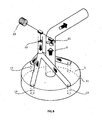
- a hood according to the prior art and the present invention comprises:
- said ventilation means comprise:
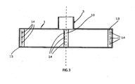
- each one of said outflow channels 13 is in a generally cylindrical or prismatic shape, and is further provided with one or more outflow ports 14, which are:
- outflow ports are arranged in a coherent manner, in the sense that the outflow ports of two contiguous channels 13 are in no case opposing each other, but are rather turned in the same direction, i.e. facing the same way relative to a single direction of rotation extending horizontally over the inner surface of said cylindrical member 11.
- said cylindrical member 11 terminates at its bottom with a lower rim 120 that is abundantly spaced away from the cooking surface or hob 10 lying therebelow, so as to avoid interfering with the good accessibility of said cooking surface from all sides thereof or, still worse, preventing the same cooking surface from being capable of being conveniently accessed to from all sides thereof by an operator.
- the inner portion of said cylindrical member 11 is provided with the afore-described plurality of outflow ports 14 in an arrangement in which they are distributed with a certain regularity along the perimeter of such portion.
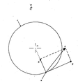
- the same air streams will be blown out through said outflow ports 14, thereby being converted into respective air jets "g" that are blown in a concordant manner all along the inner surface of said cylindrical member 11.
- the air velocity at such point can be represented by a vector having three components, i.e. an ascensional or upward component, a radial component directed towards said axis X, and a third tangential component.
- Such curve can be noticed to show a descending trend towards both extremities thereof, whereas in an intermediate position thereof the same curve reaches a peak at a point M.
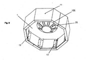
- inventive extractor hood may be provided with a filtering member 25, which - for it to be conveniently accessible and, at the same time, be prevented from interfering with the rotary, i.e. whirling circulation of the air under the hood - is preferably provided in the shape of a frustum of a cone and is applied immediately under said suction mouth 24.
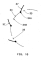
- a further advantageous embodiment of the present invention calls for said outflow ports to be provided in the form of a sequence of slots 33 opening onto the inner perimeter 30 of a horizontal channel 31 provided inside said cylindrical member 11 immediately underneath said upper planar member 1.
- Such horizontal channel 31 is delimited internally by an alternate sequence of closed vertical surfaces 34, which are spaced from each other by said slots 33, and which determine said inner perimeter 30; it is further delimited externally by a box-like casing 40 substantially coinciding with said cylindrical member 11, and at the bottom by a planar member 41 that is substantially similar and parallel to said upper planar member 1.
- Each one of said closed vertical surfaces 34 is provided at the sides with two respective edges 34A and 34B, wherein said edges are arranged in an alternate manner relative to the complete sequence of the leading and trailing edges of all said surfaces 34; on one 34A of said edges of each such closed surface 34 there is provided a respective airflow-deflecting fin or baffle 37 oriented inwardly, i.e. towards the interior of said channel 31, in a manner that is consistent relative to a single direction of circulation of the air inside said ring-like channel.
- each one of said air-flow deflecting fins 37 forms a member adapted to divert, i.e. deflect the flow of air circulating within said ring-like channel 31.
- the inclination of the fins in general can be easily modified and on the so defined inclination of the fins there depends not only the width of the respective slot, but also the rate and - to a certain extent - also the prevailing inclination of the airflow being blown into said cylindrical member 11 from such slot.
Landscapes
- Engineering & Computer Science (AREA)
- Chemical & Material Sciences (AREA)
- Combustion & Propulsion (AREA)
- Mechanical Engineering (AREA)
- General Engineering & Computer Science (AREA)
- Ventilation (AREA)
- Prevention Of Fouling (AREA)
- Filtering Of Dispersed Particles In Gases (AREA)
- Superstructure Of Vehicle (AREA)
Claims (14)
- Dunstabzugshaube, umfassend:- ein oberes planares horizontales Element (1), das geeignet ist, Brüden und Gase einzufangen und zu sammeln, die von einer darunterliegenden Kochfläche (10), an der die abzuziehenden Brüden und Wrasen erzeugt werden, nach oben strömen,- eine Saugleitung (2), die im mittleren Bereich des oberen planaren horizontalen Elements (1) offen ist,- erste Saugmittel, die der Saugleitung zugeordnet und geeignet sind, die Wrasen und Brüden daraus herauszusaugen und sie nach draußen zu blasen, wobei diese Mittel ein der Leitung (2) zugeordnetes Sauggebläse (21) umfassen,- Ventilationsmittel, die geeignet sind, dem Gemisch aus Luft und anderen Gasen, das in dem Volumen unter dem oberen planaren horizontalen Element (1) enthalten ist, eine Wirbelbewegung um eine vertikale Achse (X) zu verleihen,
wobei die Ventilationsmittel ein innen hohles zylindrisches Element (11) umfassen, von dem ein Umfangsrand auf dem äußeren Rand (110) des oberen planaren horizontalen Elements (1) platziert ist und das sich von dem oberen planaren horizontalen Element (1) vertikal nach unten erstreckt, ohne das Niveau der Kochfläche (10) oder einer ähnlichen Fläche, die darunter liegt, zu erreichen, dadurch gekennzeichnet, dass im zylindrischen Element (11) ein innen hohler horizontaler Kanal (31) definiert ist, der innen durch einen Innenumfang begrenzt ist, der eine abwechselnde Abfolge von im Wesentlichen vertikalen geschlossenen Flächen (34) umfasst, in die eine entsprechende abwechselnde Abfolge von jeweiligen Schlitzen (33) eingelagert ist, und nach unten durch ein planares Element (41) begrenzt ist. - Abzugshaube nach Anspruch 1, dadurch gekennzeichnet, dass die geschlossenen Flächen mit jeweiligen Finnen oder Leitblechen (37) versehen sind, die an einem jeweiligen vertikalen Rand (34A) davon platziert und so ausgerichtet sind, dass die abwechselnde Abfolge der Schlitze (33) und der Leitbleche (37), die den geschlossenen Flächen (34) zugeordnet sind, mehrere Ausströmöffnungen bestimmt.
- Abzugshaube nach Anspruch 2, dadurch gekennzeichnet, dass die Finnen oder Leitbleche (37) mit Steuermitteln versehen sind, die dazu geeignet sind, dass der Drehwinkel jeder derartigen Finne oder jedes derartigen Leitblechs (37) um den jeweiligen vertikalen Rand (34A) verstellt werden kann.
- Abzugshaube nach Anspruch 3, dadurch gekennzeichnet, dass die Finnen oder Leitbleche (37) über mechanische Mittel verbunden sind, die geeignet sind, die Neigung der Finnen oder Leitbleche (37) synchron und auf ähnliche Weise zu steuern.
- Abzugshaube nach Anspruch 4, dadurch gekennzeichnet, dass die mechanischen Mittel einen Verstellring (38) umfassen, der die Finnen oder Leitbleche (37) verbindet.
- Abzugshaube nach einem der vorhergehenden Ansprüche, dadurch gekennzeichnet, dass die Schlitze (33) so ausgerichtet sind, dass die jeweiligen daraus austretenden Luftströme mit einer Neigung, die wesentlich kleiner als 10° ist, in Bezug auf die Tangente (t) zum Umfang des zylindrischen Elements (11) am Anlagepunkt (P) mit dem jeweiligen Ausströmkanal in eine horizontale Richtung (a) geblasen werden.
- Abzugshaube nach einem der vorhergehenden Ansprüche, dadurch gekennzeichnet, dass sich das Verhältnis der Höhe (h1) des zylindrischen Elements (11) zum Durchmesser oder der größten Abmessung (D1) des oberen planaren Elements (1) irgendwo zwischen 3,25 und 4,0 liegt.
- Abzugshaube nach einem der vorhergehenden Ansprüche, dadurch gekennzeichnet, dass das Verhältnis der Summe der Strömungsraten der Schlitze (33) zu der Strömungsrate der Saugleitung (2) irgendwo zwischen 0,6 und 1,0 liegt.
- Abzugshaube nach einem der vorhergehenden Ansprüche, dadurch gekennzeichnet, dass die Luftaustauschhäufigkeit, d. h. die Häufigkeit, mit der die im zylindrischen Element (11) enthaltene Luft, gegen die pro Zeiteinheit aus den Schlitzen (33) geblasene Luft ausgetauscht wird, irgendwo zwischen 35 und 45 mal pro Minute liegt.
- Abzugshaube nach einem der vorhergehenden Ansprüche, dadurch gekennzeichnet, dass die Winkelgeschwindigkeit des sich drehenden, d. h. wirbelnden, Umlaufs der Luft und Wrasen, wie sie durch die Ventilationsmittel erzeugt und entlang der äußersten Bahn in dem zylindrischen Element (11) gemessen wird, irgendwo zwischen 50 und 60 rpm liegt.
- Abzugshaube nach einem der vorhergehenden Ansprüche, dadurch gekennzeichnet, dass das Verhältnis der durchschnittlichen äußersten Tangentialgeschwindigkeit (V1) des sich drehenden oder wirbelnden Luftumlaufs zu der Luftausströmgeschwindigkeit aus den Schlitzen (33) irgendwo zwischen 4,0 und 6,0 liegt.
- Abzugshaube nach einem der vorhergehenden Ansprüche, dadurch gekennzeichnet, dass die ersten Saugmittel und die Ventilationsmittel zur Erzeugung des wirbelnden Luftumlaufs jeweilige Gebläse (21, 22) umfassen, wobei diese beiden Gebläse mechanisch mit ein und demselben Antriebsmotor (23) verbunden sind.
- Abzugshaube nach einem der vorhergehenden Ansprüche, dadurch gekennzeichnet, dass in der Nähe der oder an der Saugmündung (24) der Saugleitung (2) ein Filterelement (25) untergebracht ist, das sich mindestens teilweise in das von dem zylindrischen Element (11) umschlossene Volumen in der Form eines Kegelstumpfs erstreckt.
- Kochanordnung, umfassend:- eine Abzugshaube nach einem der vorhergehenden Ansprüche,- eine Kochfläche oder ein Kochfeld (10), die bzw. das unter der Abzugshaube liegt, dadurch gekennzeichnet, dass das Verhältnis der maximalen horizontalen Abmessung des zylindrischen Elements (11) zu dem Abstand seines unteren Rands (120) von der Kochfläche oder dem Kochfeld (10), die bzw. das darunterliegt, irgendwo zwischen 0,75 und 1,0 liegt.
Priority Applications (1)
| Application Number | Priority Date | Filing Date | Title |
|---|---|---|---|
| EP09004438.9A EP2088377B1 (de) | 2006-07-27 | 2007-07-26 | Verbesserungen an der Entlüftungsanordnung einer Rauchabzugshaube |
Applications Claiming Priority (1)
| Application Number | Priority Date | Filing Date | Title |
|---|---|---|---|
| ITPN20060058 ITPN20060058A1 (it) | 2006-07-27 | 2006-07-27 | Cappa di aspirazione a ventilazione perfezionata |
Related Child Applications (2)
| Application Number | Title | Priority Date | Filing Date |
|---|---|---|---|
| EP09004438.9A Division EP2088377B1 (de) | 2006-07-27 | 2007-07-26 | Verbesserungen an der Entlüftungsanordnung einer Rauchabzugshaube |
| EP09004438.9A Division-Into EP2088377B1 (de) | 2006-07-27 | 2007-07-26 | Verbesserungen an der Entlüftungsanordnung einer Rauchabzugshaube |
Publications (3)
| Publication Number | Publication Date |
|---|---|
| EP1887286A2 EP1887286A2 (de) | 2008-02-13 |
| EP1887286A3 EP1887286A3 (de) | 2008-07-16 |
| EP1887286B1 true EP1887286B1 (de) | 2014-11-19 |
Family
ID=38511360
Family Applications (2)
| Application Number | Title | Priority Date | Filing Date |
|---|---|---|---|
| EP20070113229 Not-in-force EP1887286B1 (de) | 2006-07-27 | 2007-07-26 | Verbesserungen an der Entlüftungsanordnung einer Rauchabzugshaube |
| EP09004438.9A Not-in-force EP2088377B1 (de) | 2006-07-27 | 2007-07-26 | Verbesserungen an der Entlüftungsanordnung einer Rauchabzugshaube |
Family Applications After (1)
| Application Number | Title | Priority Date | Filing Date |
|---|---|---|---|
| EP09004438.9A Not-in-force EP2088377B1 (de) | 2006-07-27 | 2007-07-26 | Verbesserungen an der Entlüftungsanordnung einer Rauchabzugshaube |
Country Status (2)
| Country | Link |
|---|---|
| EP (2) | EP1887286B1 (de) |
| IT (1) | ITPN20060058A1 (de) |
Families Citing this family (17)
| Publication number | Priority date | Publication date | Assignee | Title |
|---|---|---|---|---|
| EP2196738B1 (de) * | 2008-12-10 | 2013-10-23 | Electrolux Home Products Corporation N.V. | Absaughaube |
| ES2427831T3 (es) * | 2008-12-10 | 2013-11-04 | Electrolux Home Products Corporation N.V. | Campana de succión |
| ATE549583T1 (de) * | 2008-12-10 | 2012-03-15 | Electrolux Home Prod Corp | Abzugshaube |
| CN102954514B (zh) * | 2011-08-27 | 2016-08-17 | 博西华电器(江苏)有限公司 | 抽油烟机及其龙卷风产生装置 |
| IT201600071189A1 (it) * | 2016-07-07 | 2018-01-07 | B S Service S R L | Cappa aspirante per cucine con flusso direzionale. |
| US10731868B2 (en) | 2016-07-07 | 2020-08-04 | B.S. Service S.R.L. | Kitchen extractor hood with directional flow |
| IT201600071188A1 (it) * | 2016-07-07 | 2018-01-07 | B S Service S R L | Cappa aspirante per cucine con flusso a vortice. |
| CA3028069C (en) * | 2016-07-07 | 2023-07-18 | B.S. Service S.R.L. | Kitchen extractor hood with vortex flow |
| CN106439964B (zh) * | 2016-09-30 | 2019-11-12 | 宁波方太厨具有限公司 | 一种吸油烟机 |
| CN106594826A (zh) * | 2016-12-02 | 2017-04-26 | 宁波方太厨具有限公司 | 一种旋吸式吸油烟机 |
| CN106594834B (zh) * | 2016-12-23 | 2019-08-23 | 宁波方太厨具有限公司 | 一种吸油烟机的旋流辅助装置 |
| CN108105824A (zh) * | 2018-01-16 | 2018-06-01 | 青岛海尔智慧厨房电器有限公司 | 一种油烟机汲烟器及油烟机 |
| DE102019206240A1 (de) * | 2019-04-30 | 2020-11-05 | BSH Hausgeräte GmbH | Dunstabzugsvorrichtung, Küchengerät mit Kochfeld und Dunstabzugsvorrichtung und Verfahren zum Betreiben einer Dunstabzugsvorrichtung |
| CN111089319A (zh) * | 2019-12-31 | 2020-05-01 | 华帝股份有限公司 | 一种吸油烟机 |
| CN112569719B (zh) * | 2020-12-21 | 2024-07-02 | 玉环太平洋机械有限公司 | 顶吸式油雾分离净化器 |
| KR102469350B1 (ko) * | 2020-12-21 | 2022-11-23 | 주식회사 포스코 | 집진장치 및 집진방법 |
| CN117562008B (zh) * | 2023-12-28 | 2025-11-04 | 广东工业大学 | 一种可潜浮式深海桁架养殖网箱 |
Family Cites Families (10)
| Publication number | Priority date | Publication date | Assignee | Title |
|---|---|---|---|---|
| DE3208622C1 (de) | 1982-03-10 | 1983-12-15 | Fraunhofer-Gesellschaft zur Förderung der angewandten Forschung e.V., 8000 München | Abzug zur Absaugung von Gasen,Daempfen und Schwebstoffen |
| JPS63267855A (ja) | 1987-04-24 | 1988-11-04 | Nippon Air Curtain Kk | 人工竜巻発生機構による局所排気装置 |
| JPH01114650A (ja) | 1987-10-26 | 1989-05-08 | Matsushita Electric Works Ltd | 調理用排煙処理装置 |
| JPH02131142A (ja) | 1988-11-11 | 1990-05-18 | Usui Internatl Ind Co Ltd | 排気ガス浄化用触媒を担持するための金属製担持母体の製造法 |
| JPH02183750A (ja) | 1989-01-06 | 1990-07-18 | Seibu Electric Ind Co Ltd | レンジフード |
| JPH0942734A (ja) | 1995-07-24 | 1997-02-14 | Sun Wave Ind Co Ltd | 加熱機器回りの排気構造 |
| JPH11311432A (ja) | 1997-05-26 | 1999-11-09 | Toto Ltd | レンジフード |
| JP3327247B2 (ja) * | 1999-01-14 | 2002-09-24 | ダイキン工業株式会社 | 換気装置 |
| JP4526780B2 (ja) * | 2003-04-30 | 2010-08-18 | 富士夫 堀 | フード装置 |
| DE102005013806A1 (de) * | 2005-03-24 | 2006-09-28 | BSH Bosch und Siemens Hausgeräte GmbH | Dunstabzugshaube |
-
2006
- 2006-07-27 IT ITPN20060058 patent/ITPN20060058A1/it unknown
-
2007
- 2007-07-26 EP EP20070113229 patent/EP1887286B1/de not_active Not-in-force
- 2007-07-26 EP EP09004438.9A patent/EP2088377B1/de not_active Not-in-force
Also Published As
| Publication number | Publication date |
|---|---|
| EP1887286A3 (de) | 2008-07-16 |
| EP2088377A2 (de) | 2009-08-12 |
| EP1887286A2 (de) | 2008-02-13 |
| ITPN20060058A1 (it) | 2008-01-28 |
| EP2088377A3 (de) | 2014-09-17 |
| EP2088377B1 (de) | 2017-06-28 |
Similar Documents
| Publication | Publication Date | Title |
|---|---|---|
| EP2088377B1 (de) | Verbesserungen an der Entlüftungsanordnung einer Rauchabzugshaube | |
| JP3395736B2 (ja) | 給排気装置 | |
| CN107923631B (zh) | 具有烹调区域和排烟设备的组合式装置 | |
| EP2240726B1 (de) | Abzugshaube mit einer abzugsverbesserungsvorrichtung | |
| CN212408779U (zh) | 具备涡轮风扇的抽油烟机 | |
| EP2196737B1 (de) | Absaughaube | |
| EP2359069B1 (de) | Absaughaube | |
| US6820609B2 (en) | Low-profile ventilation hood | |
| JP3327247B2 (ja) | 換気装置 | |
| EP1674799B1 (de) | Abzugshaube | |
| CN114763918A (zh) | 一种吸油烟机及其控制方法 | |
| JP4344398B1 (ja) | 排気フード | |
| JP2002195622A (ja) | 給排気装置 | |
| KR102788782B1 (ko) | 급식 조리실 환기장치 | |
| JP3428519B2 (ja) | トルネード型気流制御装置 | |
| JP2001027200A (ja) | トルネード型吸気・送風装置 | |
| JP2000234776A (ja) | 換気装置 | |
| EP1630477B1 (de) | Küchenlüftungshaube | |
| JP4457465B2 (ja) | 給排気装置 | |
| CN218495028U (zh) | 一种集成灶 | |
| CN216876046U (zh) | 一种烤炉 | |
| KR102540638B1 (ko) | 이중팬 및 그것을 구비한 주방배기장치 | |
| KR100897810B1 (ko) | 송풍장치 및 이를 이용한 조리기기 | |
| JP3454191B2 (ja) | 換気装置 | |
| JP2001311542A (ja) | 吸気・送風装置 |
Legal Events
| Date | Code | Title | Description |
|---|---|---|---|
| PUAI | Public reference made under article 153(3) epc to a published international application that has entered the european phase |
Free format text: ORIGINAL CODE: 0009012 |
|
| AK | Designated contracting states |
Kind code of ref document: A2 Designated state(s): AT BE BG CH CY CZ DE DK EE ES FI FR GB GR HU IE IS IT LI LT LU LV MC MT NL PL PT RO SE SI SK TR |
|
| AX | Request for extension of the european patent |
Extension state: AL BA HR MK YU |
|
| PUAL | Search report despatched |
Free format text: ORIGINAL CODE: 0009013 |
|
| AK | Designated contracting states |
Kind code of ref document: A3 Designated state(s): AT BE BG CH CY CZ DE DK EE ES FI FR GB GR HU IE IS IT LI LT LU LV MC MT NL PL PT RO SE SI SK TR |
|
| AX | Request for extension of the european patent |
Extension state: AL BA HR MK RS |
|
| RIC1 | Information provided on ipc code assigned before grant |
Ipc: F24F 7/00 20060101ALN20080612BHEP Ipc: F24C 15/20 20060101AFI20070926BHEP Ipc: F24F 7/08 20060101ALI20080612BHEP |
|
| 17P | Request for examination filed |
Effective date: 20080901 |
|
| 17Q | First examination report despatched |
Effective date: 20081006 |
|
| AKX | Designation fees paid |
Designated state(s): AT BE BG CH CY CZ DE DK EE ES FI FR GB GR HU IE IS IT LI LT LU LV MC MT NL PL PT RO SE SI SK TR |
|
| GRAP | Despatch of communication of intention to grant a patent |
Free format text: ORIGINAL CODE: EPIDOSNIGR1 |
|
| INTG | Intention to grant announced |
Effective date: 20140822 |
|
| GRAS | Grant fee paid |
Free format text: ORIGINAL CODE: EPIDOSNIGR3 |
|
| GRAA | (expected) grant |
Free format text: ORIGINAL CODE: 0009210 |
|
| AK | Designated contracting states |
Kind code of ref document: B1 Designated state(s): AT BE BG CH CY CZ DE DK EE ES FI FR GB GR HU IE IS IT LI LT LU LV MC MT NL PL PT RO SE SI SK TR |
|
| REG | Reference to a national code |
Ref country code: GB Ref legal event code: FG4D |
|
| REG | Reference to a national code |
Ref country code: CH Ref legal event code: EP |
|
| REG | Reference to a national code |
Ref country code: AT Ref legal event code: REF Ref document number: 697262 Country of ref document: AT Kind code of ref document: T Effective date: 20141215 |
|
| REG | Reference to a national code |
Ref country code: IE Ref legal event code: FG4D |
|
| REG | Reference to a national code |
Ref country code: DE Ref legal event code: R096 Ref document number: 602007039321 Country of ref document: DE Effective date: 20141231 |
|
| REG | Reference to a national code |
Ref country code: NL Ref legal event code: VDEP Effective date: 20141119 |
|
| REG | Reference to a national code |
Ref country code: AT Ref legal event code: MK05 Ref document number: 697262 Country of ref document: AT Kind code of ref document: T Effective date: 20141119 |
|
| REG | Reference to a national code |
Ref country code: LT Ref legal event code: MG4D |
|
| PG25 | Lapsed in a contracting state [announced via postgrant information from national office to epo] |
Ref country code: ES Free format text: LAPSE BECAUSE OF FAILURE TO SUBMIT A TRANSLATION OF THE DESCRIPTION OR TO PAY THE FEE WITHIN THE PRESCRIBED TIME-LIMIT Effective date: 20141119 Ref country code: FI Free format text: LAPSE BECAUSE OF FAILURE TO SUBMIT A TRANSLATION OF THE DESCRIPTION OR TO PAY THE FEE WITHIN THE PRESCRIBED TIME-LIMIT Effective date: 20141119 Ref country code: IS Free format text: LAPSE BECAUSE OF FAILURE TO SUBMIT A TRANSLATION OF THE DESCRIPTION OR TO PAY THE FEE WITHIN THE PRESCRIBED TIME-LIMIT Effective date: 20150319 Ref country code: NL Free format text: LAPSE BECAUSE OF FAILURE TO SUBMIT A TRANSLATION OF THE DESCRIPTION OR TO PAY THE FEE WITHIN THE PRESCRIBED TIME-LIMIT Effective date: 20141119 Ref country code: PT Free format text: LAPSE BECAUSE OF FAILURE TO SUBMIT A TRANSLATION OF THE DESCRIPTION OR TO PAY THE FEE WITHIN THE PRESCRIBED TIME-LIMIT Effective date: 20150319 Ref country code: LT Free format text: LAPSE BECAUSE OF FAILURE TO SUBMIT A TRANSLATION OF THE DESCRIPTION OR TO PAY THE FEE WITHIN THE PRESCRIBED TIME-LIMIT Effective date: 20141119 |
|
| PG25 | Lapsed in a contracting state [announced via postgrant information from national office to epo] |
Ref country code: GR Free format text: LAPSE BECAUSE OF FAILURE TO SUBMIT A TRANSLATION OF THE DESCRIPTION OR TO PAY THE FEE WITHIN THE PRESCRIBED TIME-LIMIT Effective date: 20150220 Ref country code: SE Free format text: LAPSE BECAUSE OF FAILURE TO SUBMIT A TRANSLATION OF THE DESCRIPTION OR TO PAY THE FEE WITHIN THE PRESCRIBED TIME-LIMIT Effective date: 20141119 Ref country code: AT Free format text: LAPSE BECAUSE OF FAILURE TO SUBMIT A TRANSLATION OF THE DESCRIPTION OR TO PAY THE FEE WITHIN THE PRESCRIBED TIME-LIMIT Effective date: 20141119 Ref country code: PL Free format text: LAPSE BECAUSE OF FAILURE TO SUBMIT A TRANSLATION OF THE DESCRIPTION OR TO PAY THE FEE WITHIN THE PRESCRIBED TIME-LIMIT Effective date: 20141119 Ref country code: CY Free format text: LAPSE BECAUSE OF FAILURE TO SUBMIT A TRANSLATION OF THE DESCRIPTION OR TO PAY THE FEE WITHIN THE PRESCRIBED TIME-LIMIT Effective date: 20141119 Ref country code: LV Free format text: LAPSE BECAUSE OF FAILURE TO SUBMIT A TRANSLATION OF THE DESCRIPTION OR TO PAY THE FEE WITHIN THE PRESCRIBED TIME-LIMIT Effective date: 20141119 |
|
| REG | Reference to a national code |
Ref country code: FR Ref legal event code: PLFP Year of fee payment: 9 |
|
| PG25 | Lapsed in a contracting state [announced via postgrant information from national office to epo] |
Ref country code: CZ Free format text: LAPSE BECAUSE OF FAILURE TO SUBMIT A TRANSLATION OF THE DESCRIPTION OR TO PAY THE FEE WITHIN THE PRESCRIBED TIME-LIMIT Effective date: 20141119 Ref country code: EE Free format text: LAPSE BECAUSE OF FAILURE TO SUBMIT A TRANSLATION OF THE DESCRIPTION OR TO PAY THE FEE WITHIN THE PRESCRIBED TIME-LIMIT Effective date: 20141119 Ref country code: SK Free format text: LAPSE BECAUSE OF FAILURE TO SUBMIT A TRANSLATION OF THE DESCRIPTION OR TO PAY THE FEE WITHIN THE PRESCRIBED TIME-LIMIT Effective date: 20141119 Ref country code: DK Free format text: LAPSE BECAUSE OF FAILURE TO SUBMIT A TRANSLATION OF THE DESCRIPTION OR TO PAY THE FEE WITHIN THE PRESCRIBED TIME-LIMIT Effective date: 20141119 Ref country code: RO Free format text: LAPSE BECAUSE OF FAILURE TO SUBMIT A TRANSLATION OF THE DESCRIPTION OR TO PAY THE FEE WITHIN THE PRESCRIBED TIME-LIMIT Effective date: 20141119 |
|
| REG | Reference to a national code |
Ref country code: DE Ref legal event code: R097 Ref document number: 602007039321 Country of ref document: DE |
|
| PLBE | No opposition filed within time limit |
Free format text: ORIGINAL CODE: 0009261 |
|
| STAA | Information on the status of an ep patent application or granted ep patent |
Free format text: STATUS: NO OPPOSITION FILED WITHIN TIME LIMIT |
|
| 26N | No opposition filed |
Effective date: 20150820 |
|
| PG25 | Lapsed in a contracting state [announced via postgrant information from national office to epo] |
Ref country code: MC Free format text: LAPSE BECAUSE OF FAILURE TO SUBMIT A TRANSLATION OF THE DESCRIPTION OR TO PAY THE FEE WITHIN THE PRESCRIBED TIME-LIMIT Effective date: 20141119 Ref country code: SI Free format text: LAPSE BECAUSE OF FAILURE TO SUBMIT A TRANSLATION OF THE DESCRIPTION OR TO PAY THE FEE WITHIN THE PRESCRIBED TIME-LIMIT Effective date: 20141119 |
|
| REG | Reference to a national code |
Ref country code: CH Ref legal event code: PL |
|
| GBPC | Gb: european patent ceased through non-payment of renewal fee |
Effective date: 20150726 |
|
| PG25 | Lapsed in a contracting state [announced via postgrant information from national office to epo] |
Ref country code: LU Free format text: LAPSE BECAUSE OF FAILURE TO SUBMIT A TRANSLATION OF THE DESCRIPTION OR TO PAY THE FEE WITHIN THE PRESCRIBED TIME-LIMIT Effective date: 20150726 |
|
| REG | Reference to a national code |
Ref country code: IE Ref legal event code: MM4A |
|
| PG25 | Lapsed in a contracting state [announced via postgrant information from national office to epo] |
Ref country code: LI Free format text: LAPSE BECAUSE OF NON-PAYMENT OF DUE FEES Effective date: 20150731 Ref country code: GB Free format text: LAPSE BECAUSE OF NON-PAYMENT OF DUE FEES Effective date: 20150726 Ref country code: CH Free format text: LAPSE BECAUSE OF NON-PAYMENT OF DUE FEES Effective date: 20150731 |
|
| REG | Reference to a national code |
Ref country code: FR Ref legal event code: PLFP Year of fee payment: 10 |
|
| PG25 | Lapsed in a contracting state [announced via postgrant information from national office to epo] |
Ref country code: IE Free format text: LAPSE BECAUSE OF NON-PAYMENT OF DUE FEES Effective date: 20150726 |
|
| PG25 | Lapsed in a contracting state [announced via postgrant information from national office to epo] |
Ref country code: MT Free format text: LAPSE BECAUSE OF FAILURE TO SUBMIT A TRANSLATION OF THE DESCRIPTION OR TO PAY THE FEE WITHIN THE PRESCRIBED TIME-LIMIT Effective date: 20141119 |
|
| PG25 | Lapsed in a contracting state [announced via postgrant information from national office to epo] |
Ref country code: BG Free format text: LAPSE BECAUSE OF FAILURE TO SUBMIT A TRANSLATION OF THE DESCRIPTION OR TO PAY THE FEE WITHIN THE PRESCRIBED TIME-LIMIT Effective date: 20141119 Ref country code: HU Free format text: LAPSE BECAUSE OF FAILURE TO SUBMIT A TRANSLATION OF THE DESCRIPTION OR TO PAY THE FEE WITHIN THE PRESCRIBED TIME-LIMIT; INVALID AB INITIO Effective date: 20070726 |
|
| REG | Reference to a national code |
Ref country code: FR Ref legal event code: PLFP Year of fee payment: 11 |
|
| PG25 | Lapsed in a contracting state [announced via postgrant information from national office to epo] |
Ref country code: TR Free format text: LAPSE BECAUSE OF FAILURE TO SUBMIT A TRANSLATION OF THE DESCRIPTION OR TO PAY THE FEE WITHIN THE PRESCRIBED TIME-LIMIT Effective date: 20141119 |
|
| PG25 | Lapsed in a contracting state [announced via postgrant information from national office to epo] |
Ref country code: BE Free format text: LAPSE BECAUSE OF FAILURE TO SUBMIT A TRANSLATION OF THE DESCRIPTION OR TO PAY THE FEE WITHIN THE PRESCRIBED TIME-LIMIT Effective date: 20141119 |
|
| REG | Reference to a national code |
Ref country code: FR Ref legal event code: PLFP Year of fee payment: 12 |
|
| PGFP | Annual fee paid to national office [announced via postgrant information from national office to epo] |
Ref country code: IT Payment date: 20220622 Year of fee payment: 16 |
|
| PGFP | Annual fee paid to national office [announced via postgrant information from national office to epo] |
Ref country code: FR Payment date: 20220615 Year of fee payment: 16 |
|
| PGFP | Annual fee paid to national office [announced via postgrant information from national office to epo] |
Ref country code: DE Payment date: 20220620 Year of fee payment: 16 |
|
| REG | Reference to a national code |
Ref country code: DE Ref legal event code: R119 Ref document number: 602007039321 Country of ref document: DE |
|
| PG25 | Lapsed in a contracting state [announced via postgrant information from national office to epo] |
Ref country code: DE Free format text: LAPSE BECAUSE OF NON-PAYMENT OF DUE FEES Effective date: 20240201 |
|
| PG25 | Lapsed in a contracting state [announced via postgrant information from national office to epo] |
Ref country code: FR Free format text: LAPSE BECAUSE OF NON-PAYMENT OF DUE FEES Effective date: 20230731 |
|
| PG25 | Lapsed in a contracting state [announced via postgrant information from national office to epo] |
Ref country code: IT Free format text: LAPSE BECAUSE OF NON-PAYMENT OF DUE FEES Effective date: 20230726 |