EP1886620B1 - Instrument médical - Google Patents
Instrument médical Download PDFInfo
- Publication number
- EP1886620B1 EP1886620B1 EP07112316.0A EP07112316A EP1886620B1 EP 1886620 B1 EP1886620 B1 EP 1886620B1 EP 07112316 A EP07112316 A EP 07112316A EP 1886620 B1 EP1886620 B1 EP 1886620B1
- Authority
- EP
- European Patent Office
- Prior art keywords
- instrument
- distal end
- advantageous embodiment
- insertion aid
- see
- Prior art date
- Legal status (The legal status is an assumption and is not a legal conclusion. Google has not performed a legal analysis and makes no representation as to the accuracy of the status listed.)
- Active
Links
- 238000005452 bending Methods 0.000 claims description 75
- 238000003780 insertion Methods 0.000 claims description 21
- 230000037431 insertion Effects 0.000 claims description 21
- 238000006073 displacement reaction Methods 0.000 claims description 17
- 230000005540 biological transmission Effects 0.000 description 43
- 239000012636 effector Substances 0.000 description 39
- 239000012530 fluid Substances 0.000 description 33
- 238000011161 development Methods 0.000 description 30
- 230000018109 developmental process Effects 0.000 description 30
- 230000009975 flexible effect Effects 0.000 description 20
- 238000000034 method Methods 0.000 description 17
- 230000006870 function Effects 0.000 description 14
- 210000000056 organ Anatomy 0.000 description 13
- 238000013461 design Methods 0.000 description 12
- CNQCVBJFEGMYDW-UHFFFAOYSA-N lawrencium atom Chemical compound [Lr] CNQCVBJFEGMYDW-UHFFFAOYSA-N 0.000 description 12
- 230000008719 thickening Effects 0.000 description 10
- 230000007246 mechanism Effects 0.000 description 9
- 230000015271 coagulation Effects 0.000 description 8
- 238000005345 coagulation Methods 0.000 description 8
- 238000001839 endoscopy Methods 0.000 description 8
- 230000002496 gastric effect Effects 0.000 description 7
- 238000005086 pumping Methods 0.000 description 6
- 238000013276 bronchoscopy Methods 0.000 description 5
- 239000007788 liquid Substances 0.000 description 5
- 230000009347 mechanical transmission Effects 0.000 description 5
- 210000001519 tissue Anatomy 0.000 description 5
- XKRFYHLGVUSROY-UHFFFAOYSA-N Argon Chemical compound [Ar] XKRFYHLGVUSROY-UHFFFAOYSA-N 0.000 description 4
- 238000002357 laparoscopic surgery Methods 0.000 description 4
- 239000000463 material Substances 0.000 description 4
- 230000006641 stabilisation Effects 0.000 description 4
- 238000011105 stabilization Methods 0.000 description 4
- 238000013459 approach Methods 0.000 description 3
- 238000001574 biopsy Methods 0.000 description 3
- 210000001035 gastrointestinal tract Anatomy 0.000 description 3
- 230000003287 optical effect Effects 0.000 description 3
- 239000002985 plastic film Substances 0.000 description 3
- 229920006255 plastic film Polymers 0.000 description 3
- 230000001953 sensory effect Effects 0.000 description 3
- 238000001356 surgical procedure Methods 0.000 description 3
- XLYOFNOQVPJJNP-UHFFFAOYSA-N water Substances O XLYOFNOQVPJJNP-UHFFFAOYSA-N 0.000 description 3
- CURLTUGMZLYLDI-UHFFFAOYSA-N Carbon dioxide Chemical compound O=C=O CURLTUGMZLYLDI-UHFFFAOYSA-N 0.000 description 2
- 229910052786 argon Inorganic materials 0.000 description 2
- 230000004888 barrier function Effects 0.000 description 2
- 210000001072 colon Anatomy 0.000 description 2
- 230000006835 compression Effects 0.000 description 2
- 238000007906 compression Methods 0.000 description 2
- 230000008878 coupling Effects 0.000 description 2
- 238000010168 coupling process Methods 0.000 description 2
- 238000005859 coupling reaction Methods 0.000 description 2
- 238000005520 cutting process Methods 0.000 description 2
- 238000011010 flushing procedure Methods 0.000 description 2
- 239000007789 gas Substances 0.000 description 2
- 238000007373 indentation Methods 0.000 description 2
- 238000002347 injection Methods 0.000 description 2
- 239000007924 injection Substances 0.000 description 2
- 238000003698 laser cutting Methods 0.000 description 2
- 210000004877 mucosa Anatomy 0.000 description 2
- 229910001000 nickel titanium Inorganic materials 0.000 description 2
- 230000000717 retained effect Effects 0.000 description 2
- 239000000523 sample Substances 0.000 description 2
- 229910001285 shape-memory alloy Inorganic materials 0.000 description 2
- 239000007921 spray Substances 0.000 description 2
- 230000003068 static effect Effects 0.000 description 2
- 230000000007 visual effect Effects 0.000 description 2
- IJGRMHOSHXDMSA-UHFFFAOYSA-N Atomic nitrogen Chemical compound N#N IJGRMHOSHXDMSA-UHFFFAOYSA-N 0.000 description 1
- 238000012323 Endoscopic submucosal dissection Methods 0.000 description 1
- HZEWFHLRYVTOIW-UHFFFAOYSA-N [Ti].[Ni] Chemical compound [Ti].[Ni] HZEWFHLRYVTOIW-UHFFFAOYSA-N 0.000 description 1
- 230000003187 abdominal effect Effects 0.000 description 1
- 238000002679 ablation Methods 0.000 description 1
- 239000003570 air Substances 0.000 description 1
- 229910045601 alloy Inorganic materials 0.000 description 1
- 239000000956 alloy Substances 0.000 description 1
- 210000003484 anatomy Anatomy 0.000 description 1
- 230000000740 bleeding effect Effects 0.000 description 1
- 239000001569 carbon dioxide Substances 0.000 description 1
- 229910002092 carbon dioxide Inorganic materials 0.000 description 1
- 230000008859 change Effects 0.000 description 1
- 238000006243 chemical reaction Methods 0.000 description 1
- 230000001419 dependent effect Effects 0.000 description 1
- 238000002405 diagnostic procedure Methods 0.000 description 1
- 239000003814 drug Substances 0.000 description 1
- 238000003384 imaging method Methods 0.000 description 1
- 210000000936 intestine Anatomy 0.000 description 1
- 230000001788 irregular Effects 0.000 description 1
- 210000002429 large intestine Anatomy 0.000 description 1
- 238000012423 maintenance Methods 0.000 description 1
- 238000004519 manufacturing process Methods 0.000 description 1
- 229910052751 metal Inorganic materials 0.000 description 1
- 239000002184 metal Substances 0.000 description 1
- JCXJVPUVTGWSNB-UHFFFAOYSA-N nitrogen dioxide Inorganic materials O=[N]=O JCXJVPUVTGWSNB-UHFFFAOYSA-N 0.000 description 1
- 230000009467 reduction Effects 0.000 description 1
- 230000003716 rejuvenation Effects 0.000 description 1
- 238000002271 resection Methods 0.000 description 1
- 238000009958 sewing Methods 0.000 description 1
- 210000002784 stomach Anatomy 0.000 description 1
- 210000004876 tela submucosa Anatomy 0.000 description 1
- 230000001225 therapeutic effect Effects 0.000 description 1
- 238000002560 therapeutic procedure Methods 0.000 description 1
- 238000011179 visual inspection Methods 0.000 description 1
Images


Classifications
-
- A—HUMAN NECESSITIES
- A61—MEDICAL OR VETERINARY SCIENCE; HYGIENE
- A61B—DIAGNOSIS; SURGERY; IDENTIFICATION
- A61B1/00—Instruments for performing medical examinations of the interior of cavities or tubes of the body by visual or photographical inspection, e.g. endoscopes; Illuminating arrangements therefor
- A61B1/005—Flexible endoscopes
- A61B1/0051—Flexible endoscopes with controlled bending of insertion part
- A61B1/0055—Constructional details of insertion parts, e.g. vertebral elements
- A61B1/0056—Constructional details of insertion parts, e.g. vertebral elements the insertion parts being asymmetric, e.g. for unilateral bending mechanisms
-
- A—HUMAN NECESSITIES
- A61—MEDICAL OR VETERINARY SCIENCE; HYGIENE
- A61B—DIAGNOSIS; SURGERY; IDENTIFICATION
- A61B1/00—Instruments for performing medical examinations of the interior of cavities or tubes of the body by visual or photographical inspection, e.g. endoscopes; Illuminating arrangements therefor
- A61B1/00131—Accessories for endoscopes
- A61B1/00135—Oversleeves mounted on the endoscope prior to insertion
-
- A—HUMAN NECESSITIES
- A61—MEDICAL OR VETERINARY SCIENCE; HYGIENE
- A61B—DIAGNOSIS; SURGERY; IDENTIFICATION
- A61B1/00—Instruments for performing medical examinations of the interior of cavities or tubes of the body by visual or photographical inspection, e.g. endoscopes; Illuminating arrangements therefor
- A61B1/012—Instruments for performing medical examinations of the interior of cavities or tubes of the body by visual or photographical inspection, e.g. endoscopes; Illuminating arrangements therefor characterised by internal passages or accessories therefor
- A61B1/018—Instruments for performing medical examinations of the interior of cavities or tubes of the body by visual or photographical inspection, e.g. endoscopes; Illuminating arrangements therefor characterised by internal passages or accessories therefor for receiving instruments
-
- A—HUMAN NECESSITIES
- A61—MEDICAL OR VETERINARY SCIENCE; HYGIENE
- A61B—DIAGNOSIS; SURGERY; IDENTIFICATION
- A61B1/00—Instruments for performing medical examinations of the interior of cavities or tubes of the body by visual or photographical inspection, e.g. endoscopes; Illuminating arrangements therefor
- A61B1/313—Instruments for performing medical examinations of the interior of cavities or tubes of the body by visual or photographical inspection, e.g. endoscopes; Illuminating arrangements therefor for introducing through surgical openings, e.g. laparoscopes
- A61B1/3132—Instruments for performing medical examinations of the interior of cavities or tubes of the body by visual or photographical inspection, e.g. endoscopes; Illuminating arrangements therefor for introducing through surgical openings, e.g. laparoscopes for laparoscopy
-
- A—HUMAN NECESSITIES
- A61—MEDICAL OR VETERINARY SCIENCE; HYGIENE
- A61B—DIAGNOSIS; SURGERY; IDENTIFICATION
- A61B17/00—Surgical instruments, devices or methods, e.g. tourniquets
- A61B17/00234—Surgical instruments, devices or methods, e.g. tourniquets for minimally invasive surgery
-
- A—HUMAN NECESSITIES
- A61—MEDICAL OR VETERINARY SCIENCE; HYGIENE
- A61B—DIAGNOSIS; SURGERY; IDENTIFICATION
- A61B17/00—Surgical instruments, devices or methods, e.g. tourniquets
- A61B17/00234—Surgical instruments, devices or methods, e.g. tourniquets for minimally invasive surgery
- A61B2017/00292—Surgical instruments, devices or methods, e.g. tourniquets for minimally invasive surgery mounted on or guided by flexible, e.g. catheter-like, means
- A61B2017/003—Steerable
-
- A—HUMAN NECESSITIES
- A61—MEDICAL OR VETERINARY SCIENCE; HYGIENE
- A61B—DIAGNOSIS; SURGERY; IDENTIFICATION
- A61B17/00—Surgical instruments, devices or methods, e.g. tourniquets
- A61B17/22—Implements for squeezing-off ulcers or the like on the inside of inner organs of the body; Implements for scraping-out cavities of body organs, e.g. bones; Calculus removers; Calculus smashing apparatus; Apparatus for removing obstructions in blood vessels, not otherwise provided for
- A61B2017/22051—Implements for squeezing-off ulcers or the like on the inside of inner organs of the body; Implements for scraping-out cavities of body organs, e.g. bones; Calculus removers; Calculus smashing apparatus; Apparatus for removing obstructions in blood vessels, not otherwise provided for with an inflatable part, e.g. balloon, for positioning, blocking, or immobilisation
- A61B2017/22055—Implements for squeezing-off ulcers or the like on the inside of inner organs of the body; Implements for scraping-out cavities of body organs, e.g. bones; Calculus removers; Calculus smashing apparatus; Apparatus for removing obstructions in blood vessels, not otherwise provided for with an inflatable part, e.g. balloon, for positioning, blocking, or immobilisation with three or more balloons
Definitions
- Endoscopy is a method used in medicine to visualize different internal regions of the human body with the aid of an imaging system which is introduced into the body via artificial or natural access routes.
- endoscopic procedures for example, the abdominal laparoscopy, the pelvic pelviscopy, the arthroscopic joints, the airway bronchoscopy or the gastrointestinal endoscopy digestive tract can be made available for visual inspection, diagnostic examinations or surgical procedures.
- Endoscopic procedures are generally much gentler on the patient than corresponding open surgery surgical procedures since access to the body via natural body orifices, e.g. Bronchoscopy, gastrointestinal endoscopy, or over relatively small incisions in the range of a few millimeters to centimeters, e.g.
- flexible instrument systems are used, in particular in gastrointestinal endoscopy and bronchoscopy, in order to be able to follow the anatomy of branched, eg, bronchial, or curved or tortuous organs, for example intestines.
- Such flexible endoscopes can be more than two meters long.
- the endoscope tip can be bent from outside and has a camera system or an optical system with a downstream image guide.
- Endoscopes used in practice often have one or two working channels through which flexible instruments, such as grasping forceps, biopsy forceps, slings or cutters, can be guided out of the endoscope tip.
- By aligning the endoscope tip can under visual control, the instrument tip be maneuvered to target tissue.
- the power transmission to the guided out at the endoscope tip surgical instruments is severely limited in such cases due to the flexible shaft and the long length.
- the given limitations of the degrees of freedom of the instruments used become clear.
- the alignment is done by controlling the angulation of the flexible endoscope.
- the rotation of the instrument is often difficult due to the length and flexibility of the working channel.
- the only real control option of the instrument is thus the feed through the working channel.
- Another disadvantage of this method is that the axis of the instrument is bound to the optical axis of the camera system, and thus the perspective on the instrument can not be changed.
- WO 2004/064600 A2 discloses an endoscope having a main body having proximal and distal ends.
- the main body consists of a shaft portion, at the proximal end of a handle and at the distal end of an instrument tip is arranged.
- a guide lumen is formed, in which an instrument arm is inserted.
- the from the WO 2004/064600 A2 known arm has a shaft on which a distal, manually abkrümmbarer end portion is formed, consisting of a number of serially arranged hinge members which are pivotable relative to one another via a decentralized cable in one direction so as toproofkrümmen the distal end portion.
- the cable is returned within the shaft to a proximal handle and connected there to an actuating lever. So is the operating lever twisted, a tensile force is applied to the cable and transmitted to the distal end portion, which curves accordingly.
- the JP 2004/008367 A further discloses a treatment instrument in the form of an instrument insertion aid of the pertinent genus.
- the insertion aid known from this prior art has a flexible shaft portion or tube, at the proximal end of an instrument handle is arranged and the distal end portion is formed into a manually bendable bending section.
- the bending portion is thereby bent by displacing an operating member in the axial direction of the handle, wherein the operating member is defined as arranged in the handle 30.
- a pull rope is provided between the operating member of the handle and the bending portion, which is guided within the shaft in a channel formed therein.
- the object of the invention is therefore to provide an instrument system of this genus, the handling of which can be improved with less technical control effort.
- the subject of this invention is an introducer comprising at least one shaft-like instrument with an angled distal end and a handle, preferably adapted to the human hand, for manual control of the angled end of the instrument.
- the instrument shaft is designed axially symmetrical, so that no preferential bending direction of the instrument shaft is present. A rotation of the instrument in a bent state is thus independent of the set angle of rotation.
- the overtube has at its distal end a cap-shaped connecting bridge, which individual channels of Overtube, in which the instruments and / or the camera system are inserted, connect end to end and to which a shaft or cable-like actuator is attached, with the rotation and the advance of the distal connecting bridge of the overtube from the proximal, extracorporeal end of the overtube are controllable.
- the instrument channels are largely decoupled mechanically from this element. This measure allows good control of the overtube with high flexibility, since, for example, when bending the overtube no compression / elongation of the instrument channels takes place, which favors a simple and gentle introduction of the system in the human body.
- Fig. 1 to 18d show variants of an instrument to be introduced here in the form of an endoscope or trocar according to the present invention
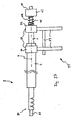
- FIGS. 19 to 25 show the instrument to be introduced in combination with a surgical instrument inserted into the instrument and an actuating device for Bending of the instrument and handling of the surgical instrument;
- FIGS. 26 to 29 show the basic embodiment of an overtube
- Fig. 30 to 38b show variants of the actuator
- Fig. 39 to 51b show variants of overtube.
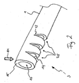
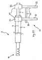
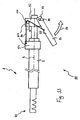
- the instrument 8 which in the present case is in the form of an endoscope, serves to align a second device 45, in particular a surgical instrument, in at least one preferred direction 81.
- the endoscopic instrument 8 consists of an instrument shaft 5 with a distal end 7, a proximal end 6.
- the distal end 7 has first, preferably hinge-like structures 3 (so-called predetermined bending points), which favor a bending of a distal instrument tip 80 in the at least one preferred direction 81.
- the instrument 8 further comprises a tension element 4, by the actuation of the bending of the instrument tip 80 can be effected.
- the instrument shaft 5 has an inner tubular element 1 and an outer tubular element 2, wherein the inner tubular element 1 is guided in the outer tubular element 2.
- the inner tube element 1 looks out of the outer tube element 2 at the distal end 7 of the instrument 8 and has the first structures 3 in the protruding section.
- the outer tube element 2 is displaceable parallel to the instrument axis 9 relative to the inner tube element 1 and is connected to the tension element 4 (see Fig. 1 ).
- the tension element 4 is actuated and thus in the area the first structures 3 causes a bend of the instrument tip 80 in the preferred direction 81.
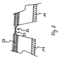
- the first structures 3 serve to produce a preferential bending direction 81 in a limited section of the inner tubular element 1 at the distal end 7 of the instrument 8. This is achieved by free spaces or indentations 25 on the inner tubular element 1, which line up in the longitudinal spacing of the inner tubular element 1.
- the notches 25 each have opposite flanks 14, which approximate at an angle of the instrument tip 80.
- the first structures 3 are preferably designed such that the axial bore of the inner tubular element 1 is not restricted (see Fig. 2 ).
- FIG. 3a to 3i An example of the design of the first structures 3 is the production of lateral recesses 11 on the inner tube element 1 at the distal end 7 of the instrument 8, as they are in different forms in the Fig. 3a to 3i are shown.
- this has a triangular cross-section, see Fig. 3a , In a further advantageous embodiment of the lateral recesses 11, this has a rectangular cross section (see Fig. 3b ). In a further advantageous embodiment of the lateral recesses 11, this has Such a cross section, wherein the recess edges 14 are parallel and the recess base 13 is rounded in each case (see Fig. 3c ). In a further advantageous embodiment of the lateral recesses 11, this has such a cross-section, wherein the recess flanks 14 extend parallel and the recess base 13 is V-shaped (see Fig. 3d ).
- the lateral recess 11 has a trapezoidal cross-section (see Fig. 3e ).
- the lateral recess 11 has a triangular cross-section, wherein the recess base has a rounding (see Fig. 3f and Fig. 3g ). This rounding can reduce local stress peaks in the region of the apex of the triangle when the instrument tip 80 is bent.
- this has a semicircular cross section (see Fig. 3h ).
- this has an irregular cross section (see Fig. 3i ).
- the lateral recesses 11 are arranged at regular intervals from each other (see Fig. 3a ). In a further advantageous embodiment of the lateral recesses 11, the lateral recesses 11 are arranged at different distances from each other (see Fig. 4a ). In a further advantageous embodiment of the lateral recesses 11, the lateral recesses 11 each have the same depth (see Fig. 3a ). In a further advantageous embodiment of the lateral recesses 11, the lateral recesses 11 each have different depths (see Fig. 4b ). In a further advantageous embodiment of the lateral recesses 11, the lateral recesses 11 each have the same width (see Fig. 3a ).
- the lateral recesses 11 each have different widths (see Fig. 4c ). In a further advantageous development of the lateral recesses 11, these each have the same shape (see Fig. 3a ). In a further advantageous embodiment of the lateral recesses 11, these each have different shapes (see Fig. 4d ). In a further advantageous embodiment of the lateral recesses 11, the lateral recesses 11 are each aligned in the same direction, preferably the preferential bending direction 81 (see Fig. 3a ). In a further advantageous embodiment of the lateral recesses 11, the lateral recesses 11 are each aligned in different directions (see Fig. 4e ).
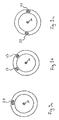
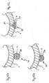
- first structures 3 provides for a connection of individual segments 16 of the inner tubular element 1 via external hinge elements 17.
- the individual pipe segments 16 are preferably arranged such that a continuous chain of segments 16 connected to each other via the hinge elements 17 is formed. These pipe segments 16 can each tilt or bend relative to the adjacent segment 16 about the pivot axis 20 of the hinge element 17, which is located between the respective adjacent segments 16.
- the segments 16 each have a continuous axial bore 19 (see Fig. 5 ).
- the hinge element 17 is connected to a segment 16 such that the pivot axis 20 of the hinge element 17 runs colinearly with a line 21 tangential to the outside of the segment (see Fig. 6a ). In a further advantageous embodiment of the hinge element 17, this is connected to a segment 16 such that the pivot axis 20 of the hinge element 17 crosses the axis 22 of the segment 16 (see FIG Fig. 6b ). In a further advantageous embodiment of the hinge element 17, the hinge element 17 is such connected to a segment 16, that the pivot axis 20 of the hinge member 17 between a line 21 tangent to the outside of the segment and the axis 22 of the segment (see Fig. 6c ). In a further advantageous embodiment of the hinge element 17, the hinge element 17 is connected to a segment 16 such that the pivot axis 20 of the hinge element 17 extends outside the segment (see Fig. 6d ).
- the first structures 3 Another example of the configuration of the first structures 3 is the connection of individual pipe segments 16 via at least one external bending element 23.
- the individual tube segments 16 are preferably arranged such that a continuous chain of segments 16 connected to one another via the external bending element 23 is produced. These segments 16 can each tilt relative to the adjacent segment 16 by deformation of the bending element 23 in the bending region 26.
- the segments 16 each have a continuous axial bore 19 (see Fig. 7 ).
- the bending element 23 is used for deformation at a bend of the instrument tip 80th
- Other elements such as the segments 16 are therefore less mechanically stressed than when using lateral recesses 11, but at the same time a deformation-related restoring force is easier to implement than with the use of hinge elements 17th
- the mechanical properties can be selectively influenced.
- shape memory alloys such as nickel-titanium alloys offer themselves as a material for the bending element 23, since they can ensure a return to the original state even with heavy deformation.
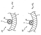
- the bending element 23 consists of a shape memory alloy, preferably of a nickel-titanium alloy. In a Another advantageous embodiment of the bending element 23, this has a taper 27 in the region of the bending region 26. This taper 27 locates the deformation when the instrument tip 80 is bent over the bending regions 26 of the bending element 23, which are preferably positioned between the segments 16 (see FIG Fig. 8 ). In a further advantageous embodiment of the bending element 23, the bending element 23 in the bending region 26 has a rectangular cross-section (see Fig. 10a ).
- the bending element 23 has this in the bending region 26 has such a cross-section, which is formed on the pipe segment outside to a convex curvature (see Fig. 10b ).
- the bending element 23 in the bending region 26 has a round cross section (see Fig. 10c ).
- this in the bending region 26 has such a cross-section, which is formed on the tube segment outside to a convex curvature and on the tube segment inside to a concave curvature (see Fig. 10d ).
- the bending element 23 in the bending region 26 exactly one ridge on (see Fig. 9a ).
- the bending element 23 in the bending region 26 has two webs (see Fig. 9b ).
- the bending element 23 in the bending region 26 has two webs, wherein the two webs are located at diametrically opposite points of the inner tubular element 1 (see Fig. 9c ).
- first structures 3 is a combination of an external bending element 23 with lateral recesses 11 integrated on the inner tubular element.
- first Structures 3 are realized whose mechanical properties can be adjusted by selective design of the bending element 23 (see Fig. 25 ).
- the pulling or pulling / pushing element 4 serves to transmit power between the outer tubular element 2 and the first structures 3.
- the tension element 4 is connected to the outer tube element 2 via a first mechanical connection 29 and to the instrument tip 80 via a second mechanical connection 30.
- the first structures 3 are preferably located between the first mechanical connection 29 and the second mechanical connection 30.
- the tension element 4 is guided by the first mechanical connection 29 to the second mechanical connection 30 on the first structures 3 on the side of the preferential bending direction 81.
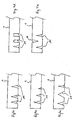
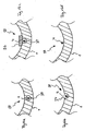
- the tension element 4 is guided by a second tension element guide 28, which is connected on the side of the preferential bending direction 81 in the region of the first structures 3 to the inner tubular element 1 (see Fig. 11a ).
- the second Switzerlandelement arrangement 28 is designed such that when moving the outer tube member 2 parallel to the instrument axis 9 in the direction of the proximal end 6 of the instrument 8, the instrument tip 80 is angled in the direction of the preferred direction 81 (see Fig. 11b ).
- the traction element 4 and the second traction element guide 28 are further optionally designed approximately on the principle of a Bowden cable such that when moving the outer tube member 2 parallel to the instrument axis 9 in the direction of the distal end 7 of the instrument 8, the instrument tip 80 is angled against the preferred direction 81 , (please refer Fig. 11c ).
- the Buchelement entry consists of a number of eyelets, which are mounted on the individual tube segments in each case in the region between the notches, such that the eyelet holes align substantially in a line.
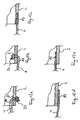
- the first mechanical connection 29 connects the proximal end 83 of the tension element 4 with the outer tube element 2 in such a way that force is transmitted to the outer tube element 2 with a force on the tension element 4 in the direction of the distal end 7 of the instrument 8.
- the first mechanical connection 29 connects the proximal end 83 of the tension member 4 to the outer tube member 2 such that, with a force on the tension member toward the proximal end 6 of the instrument 8, the force (compressive force) is transmitted to the outer tube member 2.
- the tension element 4 is guided via a lateral opening 31 in the outer tubular element 2, wherein the tension element 4 has a proximal thickening 32, for example a knot or a component mechanically fastened to the tension element 4, which passes the proximal end 83 of the tension element 4 is blocked by the lateral opening 31 in the outer tubular element 2.
- the proximal thickening is on the outside of the outer tubular element 2 (see Fig. 12a ).
- the tension element 4 is guided via a lateral opening 31 in the outer tubular element 2, wherein the tension element 4 has a proximal thickening 32, for example a knot or a component mechanically fastened to the tension element 4, which passes of the proximal end 83 of the tension element 4 is blocked by the lateral opening 31 in the outer tubular element 2.
- the proximal thickening is in this case on the inside of the outer tubular element 2 (see Fig. 12b ).
- the proximal end 83 of the tension element 4 is embedded in the wall of the outer tubular element 2 (see Fig. 12c ).
- the proximal end 83 of the tension element 4 is connected to the outside of the outer tubular element 2 with the outer tubular element 2 (see Fig. 12d ).
- the proximal end 83 of the tension element 4 on the inside of the outer tube element 2 is connected to the outer tube element 2 (see Fig. 12e ).
- the second mechanical connection 30 connects the distal end 82 of the tension element 4 with the inner tube element 1 such that, with a force on the tension element 4 in the direction of the proximal end 6 of the instrument 8, the force is transmitted to the inner tube element 1.
- the second mechanical connection 30 connects the distal end 82 of the tension member 4 to the inner tubular member 1 such that upon a force on the tension member toward the distal end 7 of the instrument 8, the force is transmitted to the inner tubular member 1.
- the tension element 4 is guided via a lateral opening 33 in the inner tube element 1, wherein the tension element 4 has a distal thickening 34, for example a knot or a component mechanically fastened to the tension element 4, which passes the passage distal end 82 of the tension element 4 is blocked by the lateral opening 33 in the inner tubular element 1.
- the distal thickening is in this case on the inside of the inner tubular element 1 (see Fig. 13a ).
- the tension element 4 is guided via a lateral opening 33 in the inner tubular element 1, wherein the tension element 4 has a distal thickening 34, for example a node or a component mechanically fastened to the tension element 4, which passes of the distal end 82 of the tension element 4 is blocked by the lateral opening 33 in the inner tubular element 1.
- the distal thickening is in this case on the outside of the inner tubular element 1 (see Fig. 13f ).
- the distal end 82 of the tension element 4 is on the outside of the inner tube member 1 is connected to the inner tube member 1, wherein the tension member 4 is brought from the proximal end 6 of the instrument 8 on the outside of the inner tube member 1 (see Fig. 13b ).
- the distal end 82 of the tension element 4 is connected on the outside of the inner tubular element 1 with the inner tubular element 1, wherein the tension element 4 from the proximal end 6 of the instrument 8 on the inside of the inner tubular element. 1 is guided and is guided over the end face 15 of the inner tube member 1 on the outside of the inner tube member 1 (see Fig. 13g ).
- the distal end 82 of the tension element 4 is connected on the outside of the inner tubular element 1 with the inner tubular element 1, wherein the tension element 4 from the proximal end 6 of the instrument 8 on the inside of the inner tubular element. 1 is guided and is guided through the wall of the inner tube member 1 on the outside of the inner tube member 1 (see Fig. 13h ).
- the distal end 82 of the tension element 4 is embedded in the wall of the inner tubular element 1 (see Fig. 13d ).
- the distal end 82 of the tension element 4 is connected to the inner tube element 1 on the inner side of the inner tube element 1, wherein the tension element 4 from the proximal end 6 of the instrument 8 on the inner side of the inner tube element. 1 is introduced (see Fig. 13i ).
- the distal end 82 of the tension element 4 is connected to the inner tube element 1 on the inner side of the inner tube element 1, wherein the tension element 4 from the proximal end 6 of the instrument 8 on the outer side of the inner tube element. 1 is introduced and via the end face 15 of the inner tube member 1 on the inside of the inner tube member 1 is guided (see Fig. 13c ).
- the distal end 82 of the tension element 4 is connected to the inner tube element 1 on the inner side of the inner tube element 1, wherein the tension element 4 from the proximal end 6 of the instrument 8 on the outer side of the inner tube element. 1 is guided and is guided by the wall of the inner tube member 1 on the inside of the inner tube member 1 (see Fig. 13e ).
- the distal end 82 of the tension element 4 has a loop 18.
- the end face 15 of the inner tube element 1 has a first Buchelement Entry 35, in which the loop 18 of the tension element 4 is guided, preferably around the distal opening 10 of the inner tube member 1 around (see Fig. 13j ).
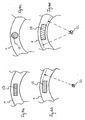
- the second tension element guide 28 is designed such that a force acting on the tension element 4 is transmitted to the first structures 3 such that a uniform bending of the instrument tip 80 takes place.
- the second Switzerlandelement Insert 28 is designed such that the tension element 4 follows the bending generated at the bend of the instrument tip 80 (see Fig. 14 ).
- the eyelets 28 mounted between the indentations on the pipe segments are wedge-shaped or thin-walled in such a way that the flanks of the notches are in contact with one another unaffected by the eyelets at the maximum angle of ablation of the first structures.
- the second tension element guide 28 has a guide element 36, which has a tubular cross-section, is mounted on the outside of the inner tubular element 1 and guides the tension element 4 inside the tubular cross-section (see FIG Fig. 15a ).
- the second tension element guide 28 has a guide element 36 which has a tubular cross section, is mounted on the inside of the inner tube element 1 and guides the tension element 4 inside the tubular cross section (see Fig. 15d ).
- the second Werelement Center 28 on a guide member 36 which has a U-shaped cross-section is attached to the outside of the inner tube member 1, that the open side of the U-shaped cross section on the outside of the inner tubular element 1 comes to rest and inside the U-shaped cross-section the tension element 4 leads (see Fig. 15b ).
- the second Werelement Entry 28 on a guide member 36 which has a U-shaped cross-section is attached to the inside of the inner tube member 1, that the open side of the U-shaped cross section on the inside of the inner tubular element 1 comes to rest and inside the U-shaped cross-section the tension element 4 leads (see Fig. 15e ).
- the outer side of the inner tubular element 1 has a groove 84 and a guide element 36, wherein the tension element 4 is guided in the groove 84 and the open side of the groove 84 is at least partially covered by the guide element 36 (please refer Fig. 15c ).
- the wall of the inner tube member 1 has a continuous, the axis 9 of the instrument 8 parallel bore 38, in which the tension element 4 is guided see Fig. 16a .
- the second Ceielement Entry 28 has the inside of the inner tubular element 1, a groove 37, in which the tension element 4 is guided (see Fig. 16b ).
- the inside of the inner tube member 1 has a groove 37 in which the tension element 4 is guided and which is at least partially covered by a guide member 36 (see Fig. 16c ).
- the tension element 4 is guided in the interior of the inner tubular element 1 (see Fig. 16d ).
- the tension element 4 is guided proximally of the first structures 3 through a second lateral bore 40 in the wall of the inner tubular element 1 (see Fig. 17 ).
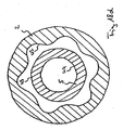
- the inner tube element 1 and the outer tube element 2 are displaced parallel to the axis 9 of the instrument 8 against each other.
- the inner tubular element 1 is guided in the outer tubular element 2.
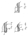
- the outer side 43 of the inner tubular element 1 is preferably in direct contact with the inner side 42 of the outer tubular element 2. It may be advantageous to reduce the friction between the outer side 43 of the inner tube member 1 and the inner side 42 of the outer tube member 2 by reducing the contact area.
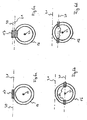
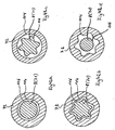
- the outer side 43 of the inner tube member 1 and the inner side of the outer tube member 2 has a circular cross-section (see FIG. 18a ).
- the outer side 43 of the inner tubular element 1 and the inner side of the outer tubular element 2 have cross-sectional shapes which rotate the inner tubular element 1 relative to the outer tubular element 2 about the axis 9 of the instrument 8 block.
- These cross-sectional shapes may be, for example, a multi-corner, or they may be star-shaped.
- these cross-sectional shapes have curves (see Fig. 18b ).
- the inner side 42 of the outer tubular element 2 has a circular cross-section and the outer side 43 of the inner tubular element 1 has a cross-sectional shape which is not circular, for example a multi-corner, or the cross section is star shaped.
- this cross-sectional shape has curves (see Fig. 18c ).
- the outer side 43 of the inner tube member 1 has a circular cross-section and the inner side 42 of the outer tube member 2 has a cross-sectional shape that is not circular, such as a multi-corner or star-shaped.
- these cross-sectional shapes have curves (see Fig. 18d ).
- Surgical effector 48 may include, for example, grasping forceps, biopsy forceps, a needle holder, a suturing device, a staple applicator, a scissors, a sling, a pouch, a clip applicator, an injection needle, a blade, a sifter, a light unit High frequency current cutting device, a laser cutting device, a balloon applicator, a stent applicator, a water jet dissector, a high frequency current coagulation device, an argon plasma coagulation device, a laser coagulation device, an ultrasonic coagulation device, a camera unit, a hook device, a spray device, a flushing device, a suction device, an electrode, or a sensory probe.
- An example of a second device 45 is a surgical instrument 85 that includes a surgical effector 48, a shaft 47, and a fifth operating element 46.
- the fifth operating element 46 is connected via the flexible shaft 47 with the surgical effector 48 (see Fig. 39 ). By operating the fifth operating element 46, the intended function of the surgical effector 48 can be adjusted.
- the fifth control element 46 is located at the proximal end 49 of the surgical instrument 85 and the surgical effector 48 is located at the distal end 50 of the surgical instrument 85.
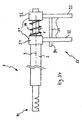
- the surgical instrument 85 is preferably positioned in the instrument 8 such that the shaft 47 of the surgical instrument 85 is guided in the inner tubular member 1 and the distal end 50 of the surgical instrument 85 can optionally be led out of the instrument tip 80 (see Fig. 19 ).
- the surgical instrument 85 is displaceable parallel to the axis 9 of the instrument 8.
- the outer side 51 of the surgical instrument 85 and the inner side 44 of the inner tubular element 1 are preferably in direct contact with each other. It may be advantageous to reduce the friction between the outside 51 of the surgical instrument 85 and the inside 44 of the inner tube member 1 by reducing the contact area. Furthermore, it may be advantageous to make the cross-sectional shape of the outer side 51 of the surgical instrument 85 and the cross-sectional shape of the inner side 44 of the inner tubular element 1 such that a rotation of the surgical instrument 85 is blocked relative to the inner tube member 1 about the axis 9 of the instrument 8.
- the outer side 51 of the surgical instrument 85 and the inner side 44 of the inner tube member 1 has a circular cross-section (see Fig. 20a ).
- the outer side 51 of the surgical instrument 85 and the inner side 44 of the inner tube member 1 cross-sectional shapes, which rotate the surgical instrument 85 relative to the inner tube member 1 about the axis 9 of the Block instruments 8.
- These cross-sectional shapes may be, for example, a multi-corner or they may be star-shaped.
- these cross-sectional shapes have curves on see Fig.
- the inner side 44 of the inner tube member 1 has a circular cross-section and the outer side 51 of the surgical instrument 85 has a cross-sectional shape that is not circular, such as a multi-corner or star-shaped.
- this cross-sectional shape has curves (see Fig. 20c ).
- the outer side 51 of the surgical instrument 85 has a circular cross-section, and has the inner side 44 of the inner tube member leinen cross-sectional shape, which is not circular, such as a multi-corner or star-shaped.
- this cross-sectional shape has curves (see Fig. 20d ).
- the surgical effector 86 may include, for example, grasping forceps, biopsy forceps, a needle holder Sewing device, a staple applicator, a pair of scissors, a loop, a bag, a clip applicator, an injection needle, a blade, a sieve, a light unit, a high-frequency current cutting device, a laser cutting device, a balloon applicator, a stent applicator, a Water jet dissector, a high frequency current coagulation device, an argon plasma coagulation device, a laser coagulation device, an ultrasonic coagulation device, a camera unit, a hook device, a spray device, a flushing device, a suction device, an electrode, or a sensory probe.
- the surgical effector 86 follows the angulation. In this way, the surgical effector 86 can be aligned (see
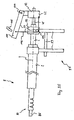
- the latter is connected to the instrument tip 80 via a fourth device 52.
- This fourth device 52 permits rotation of the surgical effector 86 about the axis 9 of the instrument 8.
- An exemplary embodiment of the fourth device 52 has mechanical transmission elements 39, which are designed such that the rotation of the surgical effector 86 can be adjusted via a force transmission element 87, for example in the form of a flexurally flexible rotary shaft.
- the force transmission element 87 leads from the fourth device 52 to the proximal end 6 of the instrument 8.
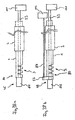
- the fourth device 52 is designed such that by force or torque introduction into the force transmission element 87, the rotation of the surgical effector 86 can be adjusted (see Fig. 21b ).
- the force transmission element 87 has a sixth operating element 112, which in such a way with the force transmission element 87 is connected, that upon actuation of the sixth operating element 112, the rotation of the surgical effector 86 can be adjusted (see Fig. 38b ).
- An advantageous embodiment of the mechanical transmission elements 39 and the power transmission element 87 has two spur gears, of which a first spur gear 88 is rotatably mounted about the axis 9 of the instrument 8 and rotatably connected to the surgical effector 86, and of which a second spur gear 89 so is rotatably mounted, that it forms a gear unit with the first spur gear 88, and is rotatably connected to the power transmission element 87.
- the force transmission element 87 is designed in the form of a shaft such that it transmits an introduced at the proximal end 6 of the instrument 8 in the force transmission element 87 torque to the second spur gear 89.
- the first spur gear 88 has a larger diameter than the second spur gear 89 to set a gear ratio between the rotational speed of the force transmitting member 87 and the surgical effector 86 of greater than one (see Fig. 31a ).
- a further advantageous embodiment of the mechanical transmission elements 39 and the power transmission element 87 has two bevel gears, of which a first bevel gear 90 is rotatably mounted about the axis 9 of the instrument 8 and is rotatably connected to the surgical effector 86, and of which a second bevel gear 91st is rotatably supported so that it forms a gear unit with the first bevel gear 90, and is operatively connected to the power transmission element 87.
- the power transmission element 87 is designed in the form of a belt drive such that it transmits to the second bevel gear 91 a tensile force introduced into the force transmission element 87 at the proximal end 6 of the instrument 8 in such a way that the second bevel gear 91 is set in rotation.
- the power transmission element 87 designed as a cable, wherein the axis of rotation of the second bevel gear 91 is substantially perpendicular to the instrument axis.
- the first bevel gear 90 has a larger diameter than the second bevel gear 91 to set a gear ratio between the rotational speed of the second bevel gear 91 and the first bevel gear 90 greater than one, and thus the tensile force in the force transmission element required for a particular torque of the surgical effector 86 87 to reduce (see Fig. 31b ).
- the surgical effector 86 optionally has a first control element 53 and a seventh control element 111.
- the seventh operating element 111 is connected to the first control element 53 in such a way that, upon actuation of the seventh operating element 111, the intended function of the surgical effector 86, preferably from the proximal end 6 of the instrument 8, can be set (see FIG Fig. 38a ).
- the first control element 53 can optionally be set such that the setting of the intended function of the surgical effector 86 is blocked. Thereby, a preferred adjustment of the intended function of the surgical effector 86 without actuation of the seventh operating element 111 can be maintained.
- the first control element 53 is a metal wire, via which either a linear force or a torque can be transmitted from the seventh operating element 111 to the surgical effector 86.
- the first control element 53 is a thread, via which a tensile force can be transmitted from the seventh operating element 111 to the surgical effector 86.
- the first control element 53 consists of at least one current-conducting one Cable via which electrical signals from the seventh control element 111 to the surgical effector 86 can be transmitted.
- electrical signals from the seventh control element 111 to the surgical effector 86 can be transmitted.
- These may be, for example, analog measuring signals such as voltages or currents, digital data or high-frequency current for operating a high-frequency effector.
- the adjustment of the rotation of the surgical effector 86 can optionally be blocked. Thereby, a preferred orientation of the fourth device 52 can be maintained without operating the sixth operating element 112.
- the control device 55 is used for manual control of the instrument 8 in various embodiments.
- the control device 55 is used in detail for manual adjustment of the angling of the instrument tip 80, optionally for manual adjustment of the advance of a surgical instrument 85 parallel to the axis 9 of the instrument 8, optionally for manual adjustment of the rotation of a surgical instrument 85 about the axis 9 of the instrument eighth optionally for manual adjustment of the intended function of a surgical effector 48, optionally for manual adjustment of the rotation of a surgical effector 86, optionally for manual adjustment of the intended function of a surgical effector 86, optionally for manual adjustment of the advancement of the instrument 8 parallel to the axis 9 of the Instruments 8 and optionally for manually adjusting the rotation of the instrument 8 about the axis 9 of the instrument. 8
- the control device 55 has a seventh device 57 for introducing a thrust force into the inner and outer tube element of the instrument and a first operating element 59 for the manual / electromotive application of a thrust force.
- the seventh device 57 has two connecting elements preferably in the form of clamps, sockets, etc., wherein the first connecting element 54 establishes a connection between the first operating element 59 and the outer tubular element 2 of the instrument 9, and the second connecting element 92 is a connection between the first operating element 59 and the inner tubular element 1 of FIG Instruments 8 manufactures.
- the first connecting element 54 and the second connecting element 92 are designed such that they can be displaced relative to one another parallel to the axis 9 of the instrument 8.
- the first connection element 54 and the second connection element 92 as well as the first control element 59 are coupled to one another in such a way that a displacement of the first connection element 54 relative to the second connection element 92 can be adjusted by actuation of the first control element 59.
- the first connecting element 54 and the second connecting element 92 are in this case connected to the instrument 8 such that when the first connecting element 54 is displaced relative to the second connecting element 92, the inner tubular element 1 is also displaced relative to the outer tubular element 2 and thereby angling of the instrument tip 80 can be adjusted.
- the first operating element 59 consists of two rod-shaped or trigger-shaped handles 93, one of which is firmly connected to the first connecting element 54 and the other is fixedly connected to the second connecting element 92.
- the first connecting element 54 can be displaced relative to the second connecting element 92.
- the displacement of the handles 93 may be guided by a guide member 94, see Fig. 22 , This consists for example of a guide rod which extends along the direction of movement of the two handles, and at one Handle attached and slidably mounted in / on the other handle.
- the first operating element 59 has two rod-shaped handles 93, one of which is fixedly connected to the first connecting element 54 and the other is firmly connected to the second connecting element 92.
- the two handles 93 are also connected to each other via a bolt or pin 95 rotatable according to the principle of scissors. By rotating the two handles 93 relative to one another about the pin 95, the first connecting element 54 can be displaced relative to the second connecting element 92. Thereby, an adjustment of the angulation of the instrument tip 80 can be made (see Fig. 32 ).
- the first control element 59 has a handle 93 in the form of a trigger, which is connected via a pivot pin 95 on one side with the one connecting element 57 pivotally connected. Furthermore, the handle 93 is operatively connected via a second power transmission element 96 in the form of a cable to the other connecting element, such that upon rotation of the handle 3 about the pivot pin 95 in a pivoting direction 97, the first connecting element 54 is used on the second connecting element 92.
- the pull cable 96 is fixed in a middle section of the trigger or lever 59 and guided over a deflection 106, which is arranged on the pivot pin 95 carrying the connecting element (see Fig. 33 ).
- the first control element 59 on gear elements, such as a gear, a rack or a toothed belt.
- gear elements such as a gear, a rack or a toothed belt.
- the first operating element 59 has at least one lever mechanism.
- the deflection 106 consists of a guide roller rotatably mounted on the one connecting element, in which the force transmission element 96 is guided.
- the deflection 106 consists of a static mechanical barrier which deforms the force transmission element 96.
- the deflection 106 consists of a tubular element in which the force transmission element 96 is guided.
- the power transmission element 96 is a drawstring or pull rope. In another exemplary embodiment of the power transmission element 96, the power transmission element 96 is a wire.
- the seventh device has a spring element 98, which is arranged between the two connecting elements and is compressed when approaching the first connecting element 54 to the second connecting element 92 (see Fig. 34 ).
- the control device 55 optionally has an eighth feed device 62 and a second operating element 63.
- the eighth advancing device 62 has a third, preferably clamping ring-like connecting element 99, which is connected to the surgical instrument 85.
- the connection between the third connection element 99 and the surgical instrument 85 is designed such that a displacement of the third connection element 99 along the axis 9 of the instrument 8 causes a displacement of the surgical instrument 85 along the axis 9 of the instrument 8.
- the second operating element 63 serves for longitudinal displacement of the third connecting element 99 and thus for longitudinal displacement of the surgical instrument 8.
- the second operating element 63 has a pull rod or cable each with handle 100, which is hinged to the third connecting element 99 via a bolt, such that by moving the pull rod 100, the third connecting element 99 parallel to the axis 9 of the instrument 8 can be moved.
- the surgical instrument 85 can be displaced relative to the instrument 8.
- the pull rod with handle 100 can be guided by a guide element 101, for example in the form of an eyelet or sleeve, which is preferably fastened to the connecting element of the inner tube element of the instrument (see Fig. 23 ).
- the second operating element 63 has a lever-shaped handle 100, which is pivotally connected to the third connecting element 99 in a rotating device 104.
- a power transmission member 103 is preferably fixed in the form of a pull rope.
- the force transmission element 103 is further connected to the third connection element 99 in such a way that when the handle 100 is pivoted in the preferred direction 105, the third connection element 99 can be displaced parallel to the axis 9 of the instrument 8 relative to the connection element of the inner tube element.
- the power transmission element 103 can optionally be deflected via one or more deflections 102, which are arranged on the connecting element of the inner tubular element (see Fig. 35 ).
- the second operating element 63 gear elements, such as a gear, a rack or a toothed belt. In a further advantageous embodiment of the second operating element 63, the second operating element 63 has at least one lever mechanism.
- the deflection 102 consists of a rotatably mounted on the connecting element of the inner tubular element guide roller, in which the zugseilformige power transmission element 103 is guided.
- the deflection 102 consists of a static mechanical barrier which deforms the force transmission element 103.
- the deflection 102 consists of a tubular element in which the force transmission element 103 is guided.
- the power transmission element 103 is a pull thread or a pull rope. In another exemplary embodiment of the power transmission element 103, the power transmission element 103 is a wire.
- the first operating element 59 has a lever-shaped handle 93, which is hinged to the second connecting element 92 of the inner tubular element of the instrument. Furthermore, the handle 93 is operatively connected to the first connecting element 54 of the outer tubular element of the instrument via the second cable-like force transmission element 96 and the second connecting element arranged such that upon pivoting of the handle 3 about the hinge 95 in the preferred direction of rotation 97, the first connecting element 54 is used to the second connection element 92.
- the power transmission element 96 can, as already indicated, optionally be deflected via one or more deflection devices 106.
- the second control element is integrated according to this embodiment.
- the first operating element further comprises a guide along the lever-shaped first operating element, which is designed such that it receives the handle 100 of the second operating element 63 can.
- the guide 107 in the present case in the form of a longitudinal slot, allows a displacement of the handle 100 of the second operating element 63, preferably along the handle 93 of the first operating element 59.
- a cable-like power transmission element 103 is connected.
- the force transmission element 103 is further connected to the third connection element 99 of the surgical instrument such that upon displacement of the handle 100 of the second control element 63 in the preferred direction 105, the third connection element 99 can be displaced parallel to the axis 9 of the instrument 8 relative to the second connection element 92 ,
- the force transmission element 103 is deflected via one or more deflections 102, which are arranged on the second connection element 92 (see FIG Fig. 36 ).
- the eighth device 62 has a spring element 108 which is arranged between the second and third connection element and by which a restoring force is exerted on the third connection element 99 when the third connection element 99 is displaced relative to the second connection element 92 can (see Fig. 37 ).
- the control device 55 optionally has a ninth device 65 and a third operating element 66 for actuating the surgical instrument.
- the ninth device 65 has for this purpose a fourth connecting element, preferably in the form of a clamping ring 109, which is connected to the surgical instrument 85.
- the mechanical connection between the fourth connecting element 109 and the surgical instrument 85 is designed such that a rotation of the fourth connecting element 109 about the axis 9 of the instrument 8 causes a rotation of the surgical instrument 85 about the axis 9 of the instrument 8.
- the third operating element 66 is furthermore such with the fourth connecting element 109 operatively connected that an actuation of the third control element 66 can cause a rotation of the fourth connecting element 109 about the axis 9 of the instrument 8.
- the third operating element 66 has a rod-shaped handle 110 which is operatively connected to the fourth connecting element 99 such that the fourth connecting element 109 can be rotated about the axis 9 of the instrument 8 by rotating the handle 110.
- the surgical instrument 85 can be rotated about the axis 9 of the instrument 8.
- the axis of the handle 110 need not necessarily coincide with the axis 9 of the instrument 8 (see Fig. 24 ) but can also be aligned with an intermediate angle of the longitudinal axis of the instrument 8 at the interposition of a deflection gear.
- the third control element 66 for this gear elements, such as a gear, a rack or a toothed belt.
- the third operating element 66 has at least one lever mechanism. It may be advantageous to combine the eighth device 62 and the ninth device 65 in such a way that the control of the rotation of the surgical instrument 85 about the axis 9 of the instrument 8 and the displacement of the surgical instrument 85 parallel to the axis 9 of the instrument 8 is controlled via a single connecting element which can be connected to the surgical instrument 85 such that both a rotation about the axis 9 of the instrument 8 and a displacement parallel to the axis 9 of the instrument 8 can be transmitted to the surgical instrument 85.
- the seventh device 57 can optionally be decoupled from the first operating element 59. As a result, an operating point setting of the first operating element 59 is possible. In a further advantageous embodiment of the seventh device 57, the adjustment of the distance of the first connection element 54 to the second connection element 92 can optionally be blocked. As a result, a preferred angling of the instrument tip 80 without actuation of the first operating element 59 can be maintained.
- the eighth device 62 can optionally be decoupled from the second operating element 63. As a result, an operating point setting of the second operating element 63 is possible. In a further advantageous embodiment of the eighth device 62, the adjustment of the displacement of the eighth device 62 parallel to the axis 9 of the instrument 8 can optionally be blocked. Thereby, a preferred position of the surgical instrument 85 can be maintained without operating the second operating element 63.
- the ninth device 65 can optionally be decoupled from the third operating element 66. As a result, an operating point setting of the third operating element 66 is possible. In a further advantageous embodiment of the ninth device 65, the setting of the rotation of the ninth device 65 about the axis 9 of the instrument 8 can optionally be blocked. Thereby, a preferred position of the surgical instrument 85 can be maintained without operating the third operating element 66.
- the fifth control element 46 is connected to the control device 55.
- the setting of the intended function of the surgical instrument 85 via the fifth control element 46 together with the operation of the instrument 8 via the first control element 59, optionally the second control element 63 and optionally the third control element 66 in the same frame possible.
- this allows the manual operation of the instrument 8 and the setting of the intended function of the surgical instrument 85, for example, with one hand.
- the seventh control element 111 is connected to the control device 55.
- This configuration makes it possible to adjust the intended function of the surgical effector 86 via the seventh operating element 111 together with the operation of the instrument 8 via at least the first operating element 59 in the same reference frame.
- this allows the manual operation of the instrument 8 and the setting of the intended function of the surgical effector 86, for example with one hand.
- the sixth control element 112 is connected to the control device 55.
- This configuration makes it possible to adjust the rotation of the surgical effector 86 via the sixth operating element 112 together with the operation of the instrument 8 via at least the first operating element 59 in the same reference system. This allows, with appropriate design of the control device 55, the manual operation of the instrument 8 and the setting of the rotation of the surgical effector 86, for example, with one hand.
- the overtube 68 serves to receive and introduce at least one eleventh device 71, preferably an instrument 8, into the human body.
- the overtube 68 serves in particular for the placement of at least one eleventh Device and a camera system or visual device in a tubular hollow organ, such as the digestive tract.
- two instruments 8 may be placed in the overtube 68.
- the camera system can optionally consist of a flexible endoscope 113 or of a camera unit 79 integrated in the overtube.
- the overtube 68 has at the distal end 69 distal openings 76 from which the inserted instruments 8 and optionally the inserted flexible endoscope 113 can exit.
- a distal end element 73 of the overtube 68 represents the reference frame of the instruments 8 and the camera system.
- the overtube 68 For the introduction of the overtube 68 in a tubular hollow organ such as the digestive tract good flexibility of the overtube 68 is advantageous, especially in the passage of highly curved tubular hollow organs such as the colon.
- good control of the reference system represented by the distal end element 73 of the overtube 68 is again advantageous in terms of control over the orientation and position of the distal end element 73 of the overtube 68.
- the combination of a good flexibility of the overtube with a good controllability of the distal end member 73 of the overtube 68 from the proximal end 70 of the overtube 68 turned out to be problematic.
- the overtube 68 has a second shaft or cable-shaped control element 74, which is connected to the distal end element 73 of the overtube 68 and extends to the proximal end 70 of the overtube 68.
- the second control element 74 thus provides a mechanical influence possibility on the distal end element 73 of the overtube 68 from the proximal end 70 of the overtube 68.
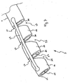
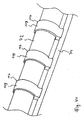
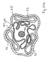
- tubular elements 72 of the overtube 68 in which the eleventh device 71, for example a Instrument 8 can be guided by the second control 74 such be decoupled that a local displacement of a tubular element 72 relative to the second control element 74 parallel to the axis 78 of the overtube 68 is possible.
- a curvature of the overtube 68 thus does not lead to a compression in the direction of the curvature lying pipe elements 72 and stretching in the opposite direction of the curvature lying pipe elements 72, which can occur against the curvature reaction forces, but to a local displacement of the pipe elements 72 relative to the second control 74, (see Fig. 41 ).
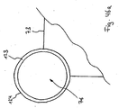
- the overtube 68 has more specifically described at the distal end 69 of the overtube 68, the distal end member 73 in the form of an end cap, which is connected to the second control element 74.
- the second control element 74 is in the form of a shaft or a cable and extends to the proximal end 70 of the overtube 68.
- the overtube has at least one tube element 72 which is connected to the distal end element 73 (see FIG Fig. 40 ).
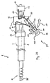
- an example of the application of the overtube 68 is the introduction of an instrument 8 into the tubular element 72.
- the instrument 8 represents the eleventh device 71.
- the instrument tip 80 of the instrument 8 preferably looks out of the distal end 69 of the overtube 68 (see FIG Fig. 25 ).
- the eleventh device 71 is displaceable parallel to the axis 78 of the overtube.
- the outer side 116 of the eleventh device 71 and the inner side 114 of the tubular element 72 are preferably in direct contact with each other. It may be advantageous to reduce the friction between the outside 116 of the eleventh device 71 and the inside 114 of the tubular element 72 by reducing the contact area. Furthermore, it may be advantageous to design the cross-sectional shape of the outer side 116 of the eleventh device 71 and the cross-sectional shape of the inner side 114 of the tubular element 72 such that that rotation of the eleventh device 71 in the tubular element 72 is blocked.
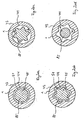
- the outer side 116 of the eleventh device 71 and the inner side 114 of the tubular element 72 has a circular cross-section (see Fig. 42a ).
- the outside 116 of the eleventh device 71 and the inside 114 of the tube element 72 have cross-sectional shapes which block a rotation of the eleventh device 71 in the tube element 72.
- These cross-sectional shapes may be, for example, a multi-corner or they may be star-shaped.
- these cross-sectional shapes have curves (see Fig. 42b ).
- the inner side 114 of the tubular element 72 has a circular cross-section and the outer side 116 of the eleventh device 71 has a cross-sectional shape which is not circular, for example a multi-corner or star-shaped.
- this cross-sectional shape has curves, (see Fig. 42c ).
- the outer side 116 of the eleventh device 71 has a circular cross-section
- the inner side 114 of the tubular element 72 has a cross-sectional shape which is not circular, for example a multi-corner or star-shaped ,
- this cross-sectional shape has curves (see Fig. 42d ).
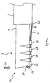
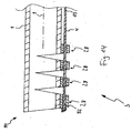
- the overtube 68 has a guide device 117.
- This guide device 117 is sleeve-shaped in the present case, extends along the overtube and is fixedly connected to the at least one tubular element 72 over the entire length of the tube.
- the second control element 74 is mounted axially displaceable, so that the tubular element 72 can be displaced locally relative to the second control element 74 parallel to the axis 78 of the overtube 68.
- the guide device 117 is designed such that the distance between the second control device 74 and the tubular element 72 can not change.
- this consists of at least one tubular or sleeve-shaped guide segment 119th
- the guide element 119 does not necessarily have to run continuously over the entire length of the overtube.
- a plurality of guide segments or sleeves 119 can be arranged at regular intervals along the overtube (see Fig. 44 ) which are all firmly connected to the respective tube element.
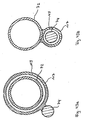
- this is firmly connected to the second control element 74 and has a closed ring structure, in which the tubular element 72 is displaceably guided (see Fig. 43a ).
- this is firmly connected to the tubular element 72 and has a closed ring structure, in which the second control element 74 is displaceably guided (see Fig. 43b ).
- this is firmly connected to the second control element 74 and has a ring structure which has a lateral opening 118 and in which the tubular element 72 is displaceably guided (see Fig. 43c ).
- this is firmly connected to the tubular element 72 and has a ring structure which has a lateral opening 118 and in which the second control element 74 is displaceably guided (see Fig. 43d ).
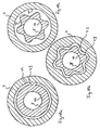
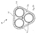
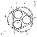
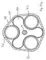
- the overtube 68 has three tubular elements 72.
- the distal cap-shaped end member 73 has three distal openings 76 on, each connect to one of the tubular elements 72.
- the tube elements 72 are connected to the distal end member 73 and are held together by this. Two of the tube elements 72 are preferably provided for receiving in each case an instrument 8, a further tube element 72 is preferably provided for receiving a flexible endoscope 113 (see Fig. 26 ).
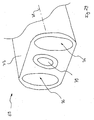
- the overtube 68 has two tube elements 72.
- the distal end member 73 has two distal openings 76, each connecting to one of the tube members 72.
- the tube elements are connected to the distal end member 73 and are held together by this.
- the two tubular elements 72 are preferably provided for receiving in each case an instrument 8.
- the distal end member 73 has an integrally disposed therein camera unit 79 (see Fig. 29 ).
- the camera unit 79 has a mechanical device or drive, via which an adjustment of the viewing angle of the camera unit 79 can take place.
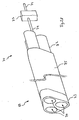
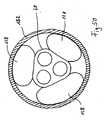
- the overtube 68 has an outer shell 75, which bundles the respective parallel-running tubular elements 72 (see Fig. 27 ).
- the second control element 74 is connected to a fourth operating element 77 at the proximal end.
- the kabbelförmige control 74 in this case has a predetermined torsional and bending stiffness similar to a Bowden cable device.
- the connection between the second control element 74 and the fourth operating element 77 is designed such that a rotation of the fourth operating element 77 causes a rotation of the second control element 74 and a Displacement of the fourth control element 77 causes a shift of the second control element 74.
- this has at least one distal opening 76 and an actuation device 120, by means of which the position or the orientation or both the position and the orientation of the distal opening 76 can be adjusted.
- the actuation device 120 has a third control element 121 and an eighth control element 122, wherein the third control element 121 is connected to the eighth control element 122 (see FIG Fig. 45 ).
- the actuation device 120 has a pneumatic actuator which can adjust the position or the alignment or both the position and the orientation of a distal opening 76 upon application of compressed air.
- the application of compressed air takes place via the third control element 121.
- the control of the application of compressed air via the eighth control 122th
- the actuation device 120 has a hydraulic actuator which can adjust the position or orientation or both the position and the orientation of a distal opening 76 when pumping in or pumping out a liquid medium.
- the pumping in or pumping out of a liquid medium takes place via the third control element 121.
- the actuation device 120 has a mechanical transmission which, when coupled to a Force or torque can adjust the position or orientation or both the position and the orientation of a distal opening 76.
- the coupling of a force or a torque takes place via the third control element 121.
- the control of the coupling of a force or a torque takes place via the eighth operating element 122.
- the tube element 72 has a mechanism which can block a displacement of an eleventh device 71, preferably an instrument 8 or a flexible endoscope 113, located in the tube element 72. Thereby, a preferred position of the eleventh device 71 in the tubular element 72 can be retained by the tubular element 72.
- the tube element 72 has a mechanism which can block a rotation of an eleventh device 71, preferably an instrument 8 or a flexible endoscope 113, located in the tube element 72.
- an eleventh device 71 preferably an instrument 8 or a flexible endoscope 113
- a preferred orientation of the eleventh device 71 in the tubular element 72 can be retained by the tubular element 72.
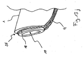
- the distal opening 76 has a tubular member 123.
- the tube member 123 is secured to the distal end member 73 such that an eleventh device 71 inserted into a tube member 72 may exit the distal opening 76 at the distal end 69 of the overtube 68.
- a flexible material hose member such as a plastic film
- the overall cross section of the distal end 69 of the overtube 68 can be reduced because the lumen of the distal opening 76 can collapse and, if there is no eleventh device 71 in the distal opening reduce the cross section of the distal end 69 of the overtube 68 therewith.
- the hose element 123 has a closed cross section and is connected to the distal end element 73 at a portion of the outer surface 124 of the hose element 123 (see FIG Fig. 46a ).
- the tube element 123 has an open cross section and is connected to the distal end element 73 in such a way that the resulting distal opening 76 has a closed cross section (see FIG Fig. 46b ).
- the tubular element 72 consists wholly or partly of a flexible material, for example a plastic film, which allows the collapse of the lumen of the tubular element 72, provided that no eleventh device 71 is located in the tubular element 72.
- a reduction of the cross section of the overtube 68 can be achieved. This is particularly useful in the introduction of the overtube 68 in a tubular hollow organ, since a small cross-section may favor a simple and gentle introduction of the overtube 68.
- the lumen of the tubular element 72 can be widened by insertion of an eleventh device 71.
- the flexibility of the overtube 68 is partially determined by the second control 74. During the introduction of the overtube 68 into a hollow organ, the highest possible flexibility is desirable. On the other hand, if the distal end has reached the intervention site, little flexibility of the overtube 68 may be desirable to achieve good controllability of the distal end member 73.
- the second control element 74 has a mechanism by means of which the flexibility of the entire second control element 74 can be set optionally.
- the second control element 74 has a mechanism by means of which the flexibility of at least one section of the second control element 74 can be set optionally.
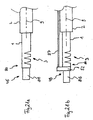
- the second control element 74 has a control segment 125.
- the control segment 125 of the second control element 74 has a fourth control element 126 and a ninth control element 127.
- the ninth control element 127 is preferably located at the proximal end 70 of the overtube 68 and is connected to the control segment 125 via the fourth control element 126.
- the control segment 125 of the second control element 74 is preferably located at the distal end 69 of the overtube 68 (see FIG Fig. 47 ).
- the control segment 125 is designed in such a way that when the ninth control element 127 is actuated via the fourth control element 126, the diffraction of the control segment 125 can be adjusted. By adjusting the diffraction of the control segment 125, it is preferable to adjust the orientation of the distal end member 73 of the overtube 68.
- stabilization of the distal end 69 of the overtube 68 is advantageous, particularly in manipulation of the target tissue with surgical instruments guided out of the distal openings 76 of the overtube 68.
- Such stabilization can be done by supporting the overtube 68 on the hollow organ wall 129.
- a tubular hollow organ with small variations in the cross-sectional area such as the colon can be such a stabilization of the distal end 69 of the overtube 68 done.
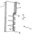
- the overtube 68 has at least one first fluid chamber 128 on the outside. Via a fluid supply 129, a fluid can be introduced into the first fluid chamber 128 or discharged from the first fluid chamber 128. By introducing a fluid into the first fluid chamber 128, the cross section of the overtube 68 can be selectively increased (see Fig. 49 ).
- stabilization of the distal end 69 of the overtube 68 in a hollow organ can be achieved by supporting the overtube 68 against the hollow organ wall 129 (see FIG Fig. 50 ).
- the overtube has a collapsible structure.
- the tubular elements 72 and the outer shell 75 may consist of a flexible material, preferably a plastic film. This can make the introduction of overtube 68 into the human body easier and gentler.
- the overtube 68 has a fluid chamber system 131 consisting of at least one second fluid chamber 130, which forms a supporting structure when filled with a fluid.
- This supporting structure may serve to erect the collapsed cross-section of the overtube 68 and, for example, facilitate insertion of an instrument 8 into the tubular members 72.
- the fluid chamber system 131 is insufficiently filled with fluid, the structure may collapse (see Fig. 51b ).
- the fluid chamber system 131 is sufficient filled with fluid, the setting of a preferred cross-sectional shape of the overtube 68 is favored, (see Fig. 51a ).
- the fluid may optionally be a gas or a liquid.
- the fluid chamber system 131 is subdivided into segments, which are preferably arranged at regular intervals along the upper tube 68.
- the segments of the fluid chamber system 131 may be selectively filled with fluid. Due to the segmental design of the fluid chamber system 131, a maintenance of a bending of the overtube 68 can be promoted when filling the fluid chamber system 131 with a fluid.
- the fluid may optionally be a gas or a liquid.
Claims (14)
- Auxiliaire d'insertion pour instruments médicaux, composé d'une tige (5) avec une extrémité distale (7) où est disposée une pièce de flexion comportant des structures (3) favorisant une flexion dans au moins une direction prédominante (81), à la différence de la tige (5), avec une extrémité proximale (6) où est disposée une poignée pour la commande manuelle de la pièce de flexion, pour sa flexion suivant un angle défini, et avec un élément de traction (4) pour l'actionnement de la pièce de flexion, où, entre la poignée et la pièce de flexion, la tige (5) se compose d'un élément tubulaire extérieur (2) qui s'étend jusqu'au niveau de l'extrémité distale (7) de la tige (5), et d'un élément tubulaire intérieur (1) guidé dans l'élément tubulaire extérieur (2) et dépassant de l'élément tubulaire extérieur (2) au niveau de l'extrémité distale (7), et où l'élément tubulaire intérieur (1) présente à son extrémité distale la pièce de flexion à l'extrémité distale duquel l'élément de traction (4) est fixé de manière décentrée, caractérisé en ce que l'élément de traction (4) est articulé à l'extrémité distale de l'élément tubulaire extérieur.
- Auxiliaire d'insertion selon la revendication 1, caractérisé en ce que les structures de la pièce de flexion consistent en une pluralité d'encoches extérieures ou de fentes dans la paroi du premier élément tubulaire, espacées longitudinalement entre elles.
- Auxiliaire d'insertion selon la revendication 1, caractérisé en ce que les structures sont formées par une pluralité de pièces tubulaires ou d'éléments espacés longitudinalement entre eux, et reliés entre eux et au premier élément tubulaire par des charnières de manière à constituer une chaîne continue de pièces tubulaires ou d'éléments.
- Auxiliaire d'insertion selon l'une des revendications précédentes, caractérisé en ce que l'élément de traction est repassé par des alésages de guidage ménagés au travers des pièces tubulaires ou éléments vers l'extrémité distale de l'autre élément tubulaire pour une transmission de force de traction et/ou de pression à l'extrémité distale de la pièce de flexion.
- Auxiliaire d'insertion selon la revendication 1, caractérisé en ce que la poignée ou la tige présentent une fixation permettant de conserver une position angulaire définie pour la pièce de flexion.
- Auxiliaire d'insertion selon l'une des revendications 1 à 5, avec deux étriers ou manettes de traction, qui à leurs premières extrémités peuvent être reliés à une des extrémités distales de l'élément tubulaire intérieur et de l'élément tubulaire extérieur pour un déplacement relatif des deux éléments tubulaires en direction axiale.
- Auxiliaire d'insertion selon la revendication 6, caractérisé par un dispositif de fixation pour la fixation de la position actuelle d'actionnement de la poignée et donc de la position angulaire de la pièce de flexion.
- Auxiliaire d'insertion selon la revendication 6 ou la revendication 7, caractérisé par un réglage de point zéro pour le réglage d'une position initiale relative des deux éléments tubulaires dans une position initiale de la poignée.
- Auxiliaire d'insertion selon l'une des revendications 1 à 8, caractérisé en ce que celui-ci comporte un étrier ou une manette de traction pouvant être relié à un instrument médical logé dans l'auxiliaire d'insertion ou fixé sur l'auxiliaire d'insertion, pour un déplacement axial dudit instrument médical.
- Auxiliaire d'insertion selon la revendication 9, caractérisé par un dispositif de fixation pour la fixation de la position actuelle d'actionnement de la poignée et donc de la position de l'instrument médical.
- Auxiliaire d'insertion selon la revendication 9 ou la revendication 10, caractérisé par un réglage de point zéro pour le réglage d'une position initiale de l'instrument médical dans une position initiale de la poignée.
- Auxiliaire d'insertion selon l'une des revendications 1 à 11, caractérisé en ce que celui-ci comporte un volant ou une manette tournante pouvant être relié à un instrument médical logé dans l'auxiliaire d'insertion ou fixé sur l'auxiliaire d'insertion, pour une rotation dudit instrument médical.
- Auxiliaire d'insertion selon la revendication 12, caractérisé par un dispositif de fixation pour la fixation de la position actuelle d'actionnement de la poignée et donc de l'alignement de l'instrument médical.
- Auxiliaire d'insertion selon la revendication 12 ou la revendication 13, caractérisé par un réglage de point zéro pour le réglage d'un alignement initial de l'instrument médical dans une position initiale de la poignée.
Applications Claiming Priority (1)
| Application Number | Priority Date | Filing Date | Title |
|---|---|---|---|
| DE102006000399A DE102006000399A1 (de) | 2006-08-10 | 2006-08-10 | Medizinisches Instrument |
Publications (3)
| Publication Number | Publication Date |
|---|---|
| EP1886620A2 EP1886620A2 (fr) | 2008-02-13 |
| EP1886620A3 EP1886620A3 (fr) | 2008-02-20 |
| EP1886620B1 true EP1886620B1 (fr) | 2013-10-02 |
Family
ID=38561697
Family Applications (1)
| Application Number | Title | Priority Date | Filing Date |
|---|---|---|---|
| EP07112316.0A Active EP1886620B1 (fr) | 2006-08-10 | 2007-07-12 | Instrument médical |
Country Status (4)
| Country | Link |
|---|---|
| US (1) | US20080051802A1 (fr) |
| EP (1) | EP1886620B1 (fr) |
| JP (1) | JP5213380B2 (fr) |
| DE (1) | DE102006000399A1 (fr) |
Families Citing this family (49)
| Publication number | Priority date | Publication date | Assignee | Title |
|---|---|---|---|---|
| US8231524B2 (en) * | 2005-09-20 | 2012-07-31 | Ai Medical Devices, Inc. | Endotracheal intubation device |
| US7993808B2 (en) * | 2005-09-30 | 2011-08-09 | Taiwan Semiconductor Manufacturing Company, Ltd. | TARC material for immersion watermark reduction |
| US7749249B2 (en) | 2006-02-21 | 2010-07-06 | Kardium Inc. | Method and device for closing holes in tissue |
| EP2021063B1 (fr) * | 2006-05-19 | 2013-05-15 | Boston Scientific Limited | Mécanisme de commande pour dispositif médical orientable |
| CA2657433A1 (fr) | 2006-06-20 | 2007-12-27 | Aortx, Inc. | Arbre de torsion et transmission de couple |
| US8449605B2 (en) | 2006-06-28 | 2013-05-28 | Kardium Inc. | Method for anchoring a mitral valve |
| US7837610B2 (en) | 2006-08-02 | 2010-11-23 | Kardium Inc. | System for improving diastolic dysfunction |
| US20090299352A1 (en) * | 2007-12-21 | 2009-12-03 | Boston Scientific Scimed, Inc. | Steerable laser-energy delivery device |
| US8137336B2 (en) | 2008-06-27 | 2012-03-20 | Boston Scientific Scimed, Inc. | Steerable medical device |
| US7780648B2 (en) | 2007-12-28 | 2010-08-24 | Boston Scientific Scimed, Inc. | Controlling movement of distal portion of medical device |
| US7823321B2 (en) * | 2008-01-28 | 2010-11-02 | The United States Of America As Represented By The Secretary Of Commerce | DNA sampling hook |
| US8048024B2 (en) | 2008-03-17 | 2011-11-01 | Boston Scientific Scimed, Inc. | Steering mechanism |
| WO2009127236A1 (fr) * | 2008-04-18 | 2009-10-22 | Fortimedix B.V. | Instrument pour applications endoscopiques ou similaires |
| US20090287304A1 (en) * | 2008-05-13 | 2009-11-19 | Kardium Inc. | Medical Device for Constricting Tissue or a Bodily Orifice, for example a mitral valve |
| US8048025B2 (en) * | 2008-07-07 | 2011-11-01 | Boston Scientific Scimed, Inc. | Multi-plane motion control mechanism |
| DE102008034425A1 (de) * | 2008-07-23 | 2010-01-28 | Polydiagnost Entwicklungs-, Produktions-, Vertriebs- Und Service Gesellschaft Mbh | Endoskop |
| US20110270234A1 (en) | 2008-07-31 | 2011-11-03 | Surgical Innovations Limited | Endoscopic surgical instrument |
| US20100069882A1 (en) * | 2008-09-18 | 2010-03-18 | Boston Scientific Scimed, Inc. | Medical device with preferential bending |
| US8092722B2 (en) * | 2008-09-30 | 2012-01-10 | Sabic Innovative Plastics Ip B.V. | Varnish compositions for electrical insulation and method of using the same |
| US8834357B2 (en) | 2008-11-12 | 2014-09-16 | Boston Scientific Scimed, Inc. | Steering mechanism |
| JP5491084B2 (ja) * | 2009-07-01 | 2014-05-14 | 幹人 黒田 | 内視鏡装置 |
| EP2482749B1 (fr) | 2009-10-01 | 2017-08-30 | Kardium Inc. | Kit de construction de tissu ou d'orifice corporel, par exemple de valvule mitrale |
| US9339264B2 (en) * | 2010-10-01 | 2016-05-17 | Cook Medical Technologies Llc | Port access visualization platform |
| EP2320262A1 (fr) * | 2009-11-10 | 2011-05-11 | Siemens Aktiengesellschaft | Dispositif d'inspection et procédé de positionnement d'un dispositif d'inspection |
| JP2013510339A (ja) * | 2009-11-10 | 2013-03-21 | シーメンス アクティエンゲゼルシャフト | 検査装置および検査装置を位置決めする方法 |
| US9050066B2 (en) | 2010-06-07 | 2015-06-09 | Kardium Inc. | Closing openings in anatomical tissue |
| US8940002B2 (en) | 2010-09-30 | 2015-01-27 | Kardium Inc. | Tissue anchor system |
| US9072511B2 (en) | 2011-03-25 | 2015-07-07 | Kardium Inc. | Medical kit for constricting tissue or a bodily orifice, for example, a mitral valve |
| EP2785497B1 (fr) * | 2011-12-02 | 2022-10-26 | Boston Scientific Scimed, Inc. | Dispositif de positionnement et ensemble articulation pour positionnement à distance d'un outil |
| DE102012103503A1 (de) | 2012-04-20 | 2013-10-24 | Aesculap Ag | Medizinisches TFT-Instrument mit schwenkbarem Elektrodenlager |
| KR20150119931A (ko) * | 2013-02-17 | 2015-10-26 | 휴먼 익스텐션스 리미티드 | 조향 가능한 의료 장치 |
| CA2938788A1 (fr) * | 2014-03-31 | 2015-10-08 | Human Extensions Ltd. | Dispositif medical orientable |
| CN106999001B (zh) | 2014-10-18 | 2019-04-16 | 史赛克欧洲控股I有限责任公司 | 具有可选择性弯折的轴杆和选择性弯折该轴杆并且当轴杆弯折时处于张紧中的缆线的手术工具 |
| WO2016138443A2 (fr) | 2015-02-26 | 2016-09-01 | Stryker Corporation | Instrument chirurgical doté d'une région d'articulation |
| JPWO2016136353A1 (ja) * | 2015-02-26 | 2017-04-27 | オリンパス株式会社 | 内視鏡システム及び内視鏡較正方法 |
| PL3092966T3 (pl) * | 2015-05-11 | 2021-05-17 | Erbe Elektromedizin Gmbh | Instrument elektrochirurgiczny |
| JP6595232B2 (ja) | 2015-07-02 | 2019-10-23 | ソニー・オリンパスメディカルソリューションズ株式会社 | 内視鏡用撮像装置、内視鏡装置、及び内視鏡用ケーブル |
| JP6599669B2 (ja) * | 2015-07-14 | 2019-10-30 | オリンパス株式会社 | 留置用器具 |
| DE102015222858A1 (de) * | 2015-11-19 | 2017-05-24 | Richard Wolf Gmbh | Schaftinstrument |
| WO2017132339A1 (fr) * | 2016-01-29 | 2017-08-03 | Boston Scientific Scimed, Inc. | Gaine pour dispositif d'imagerie |
| USD965182S1 (en) | 2016-03-14 | 2022-09-27 | Travis Christopher Porter | Fence post |
| DE102016113498A1 (de) * | 2016-07-21 | 2018-01-25 | Karl Storz Gmbh & Co. Kg | Adaptives Laryngoskop und adaptiver Spatel für ein Laryngoskop |
| US11478234B2 (en) * | 2018-03-25 | 2022-10-25 | T.A.G. Medical Products Corporation Ltd. | Working channel device for an endoscopic tool |
| WO2019200476A1 (fr) * | 2018-04-16 | 2019-10-24 | The Hospital For Sick Children | Instrument chirurgical articulé orientable |
| DE102018110620A1 (de) * | 2018-05-03 | 2019-11-07 | Konstantin Bob | Endoskopdeflecting mit distalem Abklappmechanismus |
| US11903557B2 (en) | 2019-04-30 | 2024-02-20 | Psip2 Llc | Endoscope for imaging in nonvisible light |
| DE102020134603A1 (de) * | 2020-12-22 | 2022-06-23 | Karl Storz Se & Co. Kg | Endoskopische Vorrichtung |
| CN113057721B (zh) * | 2021-03-22 | 2022-02-25 | 苏州法兰克曼医疗器械有限公司 | 一种具有快速定位装置的手术通道 |
| DE102021115475A1 (de) * | 2021-06-15 | 2022-12-15 | Konstantin Bob | Abklappmechanismus für ein Endoskop |
Family Cites Families (23)
| Publication number | Priority date | Publication date | Assignee | Title |
|---|---|---|---|---|
| US4245624A (en) * | 1977-01-20 | 1981-01-20 | Olympus Optical Co., Ltd. | Endoscope with flexible tip control |
| DE3804491A1 (de) * | 1987-12-02 | 1989-06-15 | Olympus Optical Co | Vorrichtung fuer die gehirnchirurgie |
| US4976688A (en) * | 1989-02-03 | 1990-12-11 | Rosenblum Jeffrey L | Position-adjustable thoracic catheter |
| SE8902630L (sv) * | 1989-07-31 | 1991-02-01 | Radi Medical Systems | Kateter, styranordning samt kombination daerav |
| JP2938486B2 (ja) * | 1989-12-28 | 1999-08-23 | 株式会社町田製作所 | 湾曲管およびその製造方法 |
| JP2852785B2 (ja) * | 1990-03-14 | 1999-02-03 | 株式会社町田製作所 | 可撓管用アングル |
| DE4414810C1 (de) * | 1994-04-28 | 1995-08-10 | Ep Flex Feinwerktechnik Gmbh | Endoskoprohrsystem mit einem Zugfederband und einem Stabilisierungsfederband |
| US5695513A (en) * | 1996-03-01 | 1997-12-09 | Metagen, Llc | Flexible cutting tool and methods for its use |
| DE19647761C1 (de) * | 1996-11-19 | 1998-01-08 | Epflex Feinwerktech Gmbh | Handbedieneinrichtung für ein Endoskop |
| US6332880B1 (en) * | 1996-12-19 | 2001-12-25 | Ep Technologies, Inc. | Loop structures for supporting multiple electrode elements |
| US6352503B1 (en) | 1998-07-17 | 2002-03-05 | Olympus Optical Co., Ltd. | Endoscopic surgery apparatus |
| US7637905B2 (en) * | 2003-01-15 | 2009-12-29 | Usgi Medical, Inc. | Endoluminal tool deployment system |
| US6551271B2 (en) * | 2001-04-30 | 2003-04-22 | Biosense Webster, Inc. | Asymmetrical bidirectional steerable catheter |
| US6585718B2 (en) * | 2001-05-02 | 2003-07-01 | Cardiac Pacemakers, Inc. | Steerable catheter with shaft support system for resisting axial compressive loads |
| JP4135875B2 (ja) * | 2002-06-05 | 2008-08-20 | Hoya株式会社 | 内視鏡の付加用処置具案内具 |
| US7993389B2 (en) * | 2002-06-13 | 2011-08-09 | Existent Inc. | Guidewire system |
| US7158838B2 (en) * | 2003-01-31 | 2007-01-02 | Medtronic, Inc. | Arrangement for implanting a miniaturized cardiac lead having a fixation helix |
| EP1624790A4 (fr) * | 2003-05-19 | 2008-05-21 | Usgi Medical Inc | Systeme de deploiement d'outil endoluminal |
| US7004176B2 (en) * | 2003-10-17 | 2006-02-28 | Edwards Lifesciences Ag | Heart valve leaflet locator |
| US7127033B2 (en) * | 2004-02-28 | 2006-10-24 | Xoft, Inc. | Miniature x-ray tube cooling system |
| US20060106288A1 (en) * | 2004-11-17 | 2006-05-18 | Roth Alex T | Remote tissue retraction device |
| JP2006167298A (ja) * | 2004-12-17 | 2006-06-29 | Osaka Industrial Promotion Organization | 多重導管、多重導管駆動装置、及び多重導管駆動システム |
| US20070015965A1 (en) * | 2005-07-13 | 2007-01-18 | Usgi Medical Inc. | Methods and apparatus for colonic cleaning |
-
2006
- 2006-08-10 DE DE102006000399A patent/DE102006000399A1/de not_active Withdrawn
-
2007
- 2007-07-12 EP EP07112316.0A patent/EP1886620B1/fr active Active
- 2007-08-07 JP JP2007204975A patent/JP5213380B2/ja not_active Expired - Fee Related
- 2007-08-09 US US11/836,340 patent/US20080051802A1/en not_active Abandoned
Also Published As
| Publication number | Publication date |
|---|---|
| JP5213380B2 (ja) | 2013-06-19 |
| US20080051802A1 (en) | 2008-02-28 |
| DE102006000399A1 (de) | 2008-02-14 |
| EP1886620A2 (fr) | 2008-02-13 |
| EP1886620A3 (fr) | 2008-02-20 |
| JP2008068070A (ja) | 2008-03-27 |
Similar Documents
| Publication | Publication Date | Title |
|---|---|---|
| EP1886620B1 (fr) | Instrument médical | |
| EP2676597B1 (fr) | Enveloppe d'endoscope, agencement d'endoscope et procédé de mise à disposition d'un agencement d'endoscope | |
| DE69933527T2 (de) | Elektrodenvorrichtung für mikrowellenoperationen | |
| EP1055397B1 (fr) | Instrument médical de préparation de tissus | |
| DE4340707C2 (de) | Manipulator | |
| DE19780707C2 (de) | Vorrichtung für die perkutane Chirurgie | |
| EP2103264B1 (fr) | Instrument médical | |
| EP3028623B1 (fr) | Instrument endoscopique et systeme d'instrument endoscopique | |
| AT413940B (de) | Laparoskopisches instrument | |
| EP2415403A1 (fr) | Instrument chirurgical articulable | |
| DE102017107978B4 (de) | Endoskopkopf mit schwenkbarer Kamera- und Arbeitskanal-Einheit | |
| EP1164917A1 (fr) | Dispositif permettant de traiter un patient de maniere intracorporelle et a invasion minimale | |
| EP2460458B1 (fr) | Système d'instruments endoscopiques | |
| DE202009017988U1 (de) | Chirurgisches Instrument | |
| DE102010030285A1 (de) | Vorrichtung und Verfahren zum Einbringen und Halten einer intraabdominalen Kamera | |
| DE4400409A1 (de) | Mikrochirurgisches Instrument | |
| DE10149421A1 (de) | Instrument für die minimal-invasive Chirurgie | |
| EP2361040B1 (fr) | Instrument pour chirurgie laparoscopique | |
| WO2020094193A9 (fr) | Instrument endoscopique | |
| DE4324254C1 (de) | Chirurgisches Instrument für endoskopische Operationen | |
| WO2010105649A1 (fr) | Queue tubulaire d'un instrument chirurgical et son utilisation | |
| DE202007003093U1 (de) | Chirurgisches Instrument und chirurgisches Instrumentarium | |
| DE19721138C1 (de) | Endoskop, insbesondere Mediastinoskop | |
| WO2009000854A1 (fr) | Appareil chirurgical | |
| WO2010009720A1 (fr) | Endoscope commandable |
Legal Events
| Date | Code | Title | Description |
|---|---|---|---|
| PUAI | Public reference made under article 153(3) epc to a published international application that has entered the european phase |
Free format text: ORIGINAL CODE: 0009012 |
|
| PUAL | Search report despatched |
Free format text: ORIGINAL CODE: 0009013 |
|
| AK | Designated contracting states |
Kind code of ref document: A2 Designated state(s): AT BE BG CH CY CZ DE DK EE ES FI FR GB GR HU IE IS IT LI LT LU LV MC MT NL PL PT RO SE SI SK TR |
|
| AX | Request for extension of the european patent |
Extension state: AL BA HR MK YU |
|
| AK | Designated contracting states |
Kind code of ref document: A3 Designated state(s): AT BE BG CH CY CZ DE DK EE ES FI FR GB GR HU IE IS IT LI LT LU LV MC MT NL PL PT RO SE SI SK TR |
|
| AX | Request for extension of the european patent |
Extension state: AL BA HR MK YU |
|
| 17P | Request for examination filed |
Effective date: 20080819 |
|
| AKX | Designation fees paid |
Designated state(s): DE ES FR GB IT |
|
| 17Q | First examination report despatched |
Effective date: 20090317 |
|
| GRAJ | Information related to disapproval of communication of intention to grant by the applicant or resumption of examination proceedings by the epo deleted |
Free format text: ORIGINAL CODE: EPIDOSDIGR1 |
|
| GRAP | Despatch of communication of intention to grant a patent |
Free format text: ORIGINAL CODE: EPIDOSNIGR1 |
|
| RIN1 | Information on inventor provided before grant (corrected) |
Inventor name: SCHOSTEK, SEBASTIAN Inventor name: HO, CHI-NGHIA Inventor name: RIEBER, FABIAN Inventor name: SCHURR, MARC OLIVER |
|
| GRAS | Grant fee paid |
Free format text: ORIGINAL CODE: EPIDOSNIGR3 |
|
| GRAP | Despatch of communication of intention to grant a patent |
Free format text: ORIGINAL CODE: EPIDOSNIGR1 |
|
| INTG | Intention to grant announced |
Effective date: 20130702 |
|
| RIN1 | Information on inventor provided before grant (corrected) |
Inventor name: SCHURR, MARC OLIVER, PROF. DR. MED. Inventor name: SCHOSTEK, SEBASTIAN Inventor name: HO, CHI-NGHIA Inventor name: RIEBER, FABIAN |
|
| GRAA | (expected) grant |
Free format text: ORIGINAL CODE: 0009210 |
|
| AK | Designated contracting states |
Kind code of ref document: B1 Designated state(s): DE ES FR GB IT |
|
| REG | Reference to a national code |
Ref country code: GB Ref legal event code: FG4D Free format text: NOT ENGLISH |
|
| REG | Reference to a national code |
Ref country code: DE Ref legal event code: R096 Ref document number: 502007012344 Country of ref document: DE Effective date: 20131128 |
|
| PG25 | Lapsed in a contracting state [announced via postgrant information from national office to epo] |
Ref country code: ES Free format text: LAPSE BECAUSE OF FAILURE TO SUBMIT A TRANSLATION OF THE DESCRIPTION OR TO PAY THE FEE WITHIN THE PRESCRIBED TIME-LIMIT Effective date: 20131002 |
|
| REG | Reference to a national code |
Ref country code: DE Ref legal event code: R097 Ref document number: 502007012344 Country of ref document: DE |
|
| PLBE | No opposition filed within time limit |
Free format text: ORIGINAL CODE: 0009261 |
|
| STAA | Information on the status of an ep patent application or granted ep patent |
Free format text: STATUS: NO OPPOSITION FILED WITHIN TIME LIMIT |
|
| PG25 | Lapsed in a contracting state [announced via postgrant information from national office to epo] |
Ref country code: IT Free format text: LAPSE BECAUSE OF FAILURE TO SUBMIT A TRANSLATION OF THE DESCRIPTION OR TO PAY THE FEE WITHIN THE PRESCRIBED TIME-LIMIT Effective date: 20131002 |
|
| 26N | No opposition filed |
Effective date: 20140703 |
|
| REG | Reference to a national code |
Ref country code: DE Ref legal event code: R097 Ref document number: 502007012344 Country of ref document: DE Effective date: 20140703 |
|
| REG | Reference to a national code |
Ref country code: FR Ref legal event code: PLFP Year of fee payment: 10 |
|
| REG | Reference to a national code |
Ref country code: FR Ref legal event code: PLFP Year of fee payment: 11 |
|
| REG | Reference to a national code |
Ref country code: FR Ref legal event code: PLFP Year of fee payment: 12 |
|
| PGFP | Annual fee paid to national office [announced via postgrant information from national office to epo] |
Ref country code: GB Payment date: 20220725 Year of fee payment: 16 Ref country code: DE Payment date: 20220510 Year of fee payment: 16 |
|
| PGFP | Annual fee paid to national office [announced via postgrant information from national office to epo] |
Ref country code: FR Payment date: 20220725 Year of fee payment: 16 |
|
| REG | Reference to a national code |
Ref country code: DE Ref legal event code: R119 Ref document number: 502007012344 Country of ref document: DE |
|
| GBPC | Gb: european patent ceased through non-payment of renewal fee |
Effective date: 20230712 |