EP1882613A1 - Fahrzeug und fahrzeug-kommunikationssteuervorrichtung - Google Patents
Fahrzeug und fahrzeug-kommunikationssteuervorrichtung Download PDFInfo
- Publication number
- EP1882613A1 EP1882613A1 EP05738574A EP05738574A EP1882613A1 EP 1882613 A1 EP1882613 A1 EP 1882613A1 EP 05738574 A EP05738574 A EP 05738574A EP 05738574 A EP05738574 A EP 05738574A EP 1882613 A1 EP1882613 A1 EP 1882613A1
- Authority
- EP
- European Patent Office
- Prior art keywords
- vehicle
- communication
- communication device
- carrier
- frequency band
- Prior art date
- Legal status (The legal status is an assumption and is not a legal conclusion. Google has not performed a legal analysis and makes no representation as to the accuracy of the status listed.)
- Withdrawn
Links
- 238000004891 communication Methods 0.000 title claims abstract description 275
- 238000012549 training Methods 0.000 claims description 32
- 238000012545 processing Methods 0.000 claims description 4
- 230000004044 response Effects 0.000 abstract description 8
- 238000000034 method Methods 0.000 description 57
- 230000005540 biological transmission Effects 0.000 description 44
- 238000006243 chemical reaction Methods 0.000 description 35
- 230000008569 process Effects 0.000 description 29
- 230000007274 generation of a signal involved in cell-cell signaling Effects 0.000 description 10
- 230000010365 information processing Effects 0.000 description 10
- 230000003321 amplification Effects 0.000 description 7
- 238000003199 nucleic acid amplification method Methods 0.000 description 7
- 238000001514 detection method Methods 0.000 description 6
- 239000004020 conductor Substances 0.000 description 5
- 230000005672 electromagnetic field Effects 0.000 description 5
- 239000000969 carrier Substances 0.000 description 4
- 238000010586 diagram Methods 0.000 description 4
- 238000005259 measurement Methods 0.000 description 4
- 238000011156 evaluation Methods 0.000 description 3
- 238000009434 installation Methods 0.000 description 3
- 230000008901 benefit Effects 0.000 description 2
- 230000008859 change Effects 0.000 description 2
- 230000007246 mechanism Effects 0.000 description 2
- 230000010363 phase shift Effects 0.000 description 2
- 230000002238 attenuated effect Effects 0.000 description 1
- 238000012937 correction Methods 0.000 description 1
- 125000004122 cyclic group Chemical group 0.000 description 1
- 238000012938 design process Methods 0.000 description 1
- 238000011161 development Methods 0.000 description 1
- 238000003384 imaging method Methods 0.000 description 1
- 238000004519 manufacturing process Methods 0.000 description 1
- 238000012986 modification Methods 0.000 description 1
- 230000004048 modification Effects 0.000 description 1
- 230000005855 radiation Effects 0.000 description 1
- 230000009467 reduction Effects 0.000 description 1
- 230000001131 transforming effect Effects 0.000 description 1
Images


Classifications
-
- H—ELECTRICITY
- H04—ELECTRIC COMMUNICATION TECHNIQUE
- H04B—TRANSMISSION
- H04B3/00—Line transmission systems
- H04B3/54—Systems for transmission via power distribution lines
-
- B—PERFORMING OPERATIONS; TRANSPORTING
- B60—VEHICLES IN GENERAL
- B60R—VEHICLES, VEHICLE FITTINGS, OR VEHICLE PARTS, NOT OTHERWISE PROVIDED FOR
- B60R1/00—Optical viewing arrangements; Real-time viewing arrangements for drivers or passengers using optical image capturing systems, e.g. cameras or video systems specially adapted for use in or on vehicles
- B60R1/20—Real-time viewing arrangements for drivers or passengers using optical image capturing systems, e.g. cameras or video systems specially adapted for use in or on vehicles
- B60R1/22—Real-time viewing arrangements for drivers or passengers using optical image capturing systems, e.g. cameras or video systems specially adapted for use in or on vehicles for viewing an area outside the vehicle, e.g. the exterior of the vehicle
- B60R1/23—Real-time viewing arrangements for drivers or passengers using optical image capturing systems, e.g. cameras or video systems specially adapted for use in or on vehicles for viewing an area outside the vehicle, e.g. the exterior of the vehicle with a predetermined field of view
- B60R1/26—Real-time viewing arrangements for drivers or passengers using optical image capturing systems, e.g. cameras or video systems specially adapted for use in or on vehicles for viewing an area outside the vehicle, e.g. the exterior of the vehicle with a predetermined field of view to the rear of the vehicle
-
- B—PERFORMING OPERATIONS; TRANSPORTING
- B60—VEHICLES IN GENERAL
- B60T—VEHICLE BRAKE CONTROL SYSTEMS OR PARTS THEREOF; BRAKE CONTROL SYSTEMS OR PARTS THEREOF, IN GENERAL; ARRANGEMENT OF BRAKING ELEMENTS ON VEHICLES IN GENERAL; PORTABLE DEVICES FOR PREVENTING UNWANTED MOVEMENT OF VEHICLES; VEHICLE MODIFICATIONS TO FACILITATE COOLING OF BRAKES
- B60T7/00—Brake-action initiating means
- B60T7/02—Brake-action initiating means for personal initiation
- B60T7/04—Brake-action initiating means for personal initiation foot actuated
- B60T7/042—Brake-action initiating means for personal initiation foot actuated by electrical means, e.g. using travel or force sensors
-
- B—PERFORMING OPERATIONS; TRANSPORTING
- B60—VEHICLES IN GENERAL
- B60R—VEHICLES, VEHICLE FITTINGS, OR VEHICLE PARTS, NOT OTHERWISE PROVIDED FOR
- B60R2300/00—Details of viewing arrangements using cameras and displays, specially adapted for use in a vehicle
- B60R2300/20—Details of viewing arrangements using cameras and displays, specially adapted for use in a vehicle characterised by the type of display used
- B60R2300/207—Details of viewing arrangements using cameras and displays, specially adapted for use in a vehicle characterised by the type of display used using multi-purpose displays, e.g. camera image and navigation or video on same display
-
- B—PERFORMING OPERATIONS; TRANSPORTING
- B60—VEHICLES IN GENERAL
- B60R—VEHICLES, VEHICLE FITTINGS, OR VEHICLE PARTS, NOT OTHERWISE PROVIDED FOR
- B60R2300/00—Details of viewing arrangements using cameras and displays, specially adapted for use in a vehicle
- B60R2300/80—Details of viewing arrangements using cameras and displays, specially adapted for use in a vehicle characterised by the intended use of the viewing arrangement
- B60R2300/8066—Details of viewing arrangements using cameras and displays, specially adapted for use in a vehicle characterised by the intended use of the viewing arrangement for monitoring rearward traffic
-
- B—PERFORMING OPERATIONS; TRANSPORTING
- B60—VEHICLES IN GENERAL
- B60T—VEHICLE BRAKE CONTROL SYSTEMS OR PARTS THEREOF; BRAKE CONTROL SYSTEMS OR PARTS THEREOF, IN GENERAL; ARRANGEMENT OF BRAKING ELEMENTS ON VEHICLES IN GENERAL; PORTABLE DEVICES FOR PREVENTING UNWANTED MOVEMENT OF VEHICLES; VEHICLE MODIFICATIONS TO FACILITATE COOLING OF BRAKES
- B60T2220/00—Monitoring, detecting driver behaviour; Signalling thereof; Counteracting thereof
- B60T2220/04—Pedal travel sensor, stroke sensor; Sensing brake request
-
- B—PERFORMING OPERATIONS; TRANSPORTING
- B60—VEHICLES IN GENERAL
- B60T—VEHICLE BRAKE CONTROL SYSTEMS OR PARTS THEREOF; BRAKE CONTROL SYSTEMS OR PARTS THEREOF, IN GENERAL; ARRANGEMENT OF BRAKING ELEMENTS ON VEHICLES IN GENERAL; PORTABLE DEVICES FOR PREVENTING UNWANTED MOVEMENT OF VEHICLES; VEHICLE MODIFICATIONS TO FACILITATE COOLING OF BRAKES
- B60T2270/00—Further aspects of brake control systems not otherwise provided for
- B60T2270/82—Brake-by-Wire, EHB
-
- H—ELECTRICITY
- H04—ELECTRIC COMMUNICATION TECHNIQUE
- H04B—TRANSMISSION
- H04B2203/00—Indexing scheme relating to line transmission systems
- H04B2203/54—Aspects of powerline communications not already covered by H04B3/54 and its subgroups
- H04B2203/5462—Systems for power line communications
- H04B2203/547—Systems for power line communications via DC power distribution
-
- H—ELECTRICITY
- H04—ELECTRIC COMMUNICATION TECHNIQUE
- H04L—TRANSMISSION OF DIGITAL INFORMATION, e.g. TELEGRAPHIC COMMUNICATION
- H04L27/00—Modulated-carrier systems
- H04L27/26—Systems using multi-frequency codes
- H04L27/2601—Multicarrier modulation systems
Definitions
- the present invention relates to a vehicle and an in-vehicle communication control device
- a device using an inverter is widely used in a vehicle.
- Switching operation of an inverter as a device for controlling a large current causes a large noise.
- the noise and an electromagnetic wave are superimposed on a communication cable signal, which lowers the communication performance.
- a communication cable has a branched portion or has an open end, reflection by impedance mismatch may cause a sudden signal attenuation which is called a notch attenuation in a particular frequency.
- the signal attenuation is caused in accordance with the length.
- the attenuation ratio is higher as the frequency of the carrier is higher.
- the noise and the signal attenuation are large factors to lower the communication line communication performance. Since in a vehicle, a radio and television radio wave are received, it is necessary to prevent the noise and the electromagnetic wave from behaving as noise sources in the radio and the television communication frequency band.
- a multi-channel communication can be considered instead of time-division communication having an insufficient control response.
- a plurality of communication lines should be arranged, which causes a problem that the weight of the communication line increases the weight of the vehicle.
- JP-A-11-266251 discloses an in-vehicle wiring device including a control unit arranged in a predetermined position in a vehicle for controlling the entire vehicle and a main cable for transmitting a control system signal to an electric component control unit.
- the main cable is formed by a leak cable causing an electromagnetic field in accordance with the control system signal.
- More than one electric component control units are arranged in the vicinity apart from the main cable.
- a transmission/reception antenna is provided for performing radio communication with the main cable via the electromagnetic field.
- JP-A-9-55986 discloses an in-vehicle communication system including an acquisition controller and a plurality of reception controllers, each arranged for various controllers successively connected by a predetermined transmission medium for controlling the in-vehicle system.
- the acquisition controller acquires common information to be used commonly and outputs the common information to the transmission medium so as to be transmitted to the respective reception controllers.
- the reception controllers perform input processes for performing input to the various controllers corresponding to the received common information, on the transmission medium, and outputs the received common information to the transmission medium so as to transmit it to other reception controller if necessary.
- JP-A-2003-116187 discloses an in-vehicle LAN system including: a main control device having control signal generating means for outputting a control signal containing an ID for controlling on-vehicle electric devices to a power line for supplying power to the electric devices; and an electric device control unit for detecting a control signal containing an ID from the power line and controlling the electric devices.
- JP-A-2003-318925 discloses an on-vehicle communication system including a plurality of electric devices connected to a first communication line which also supplies power to electric devices, wherein some of the electric devices are also connected as special electric devices to a second communication line. Between the special electric devices, communication is performed by both of the first communication line and the second communication line.
- JP-A-11-266251 discloses an in-vehicle wiring device using a main cable formed by a leak cable.
- the network currently used in a vehicle should be replaced by the leak cable and the wiring device cannot be applied to a current vehicle.
- a new leak cable should be installed. This increases the weight of the vehicle body.
- radio and television signals are received. No consideration is taken on that these are noise sources.
- JP-A-9-55986 discloses an in-vehicle communication system which requires installation of a dedicated communication cable instead of the network currently used in an vehicle and has a problem that the system cannot be applied to the current vehicle. Moreover, when using the current network, a new cable should be installed and the weight of the vehicle body is increased.
- an in-vehicle LAN system disclosed in JP-A-2003-116187 and an in-vehicle communication system disclosed in JP-A-2003-318925 use a power line carrier but take no consideration neither on preventing signal mixing with the radio and the television used in the vehicle nor on preventing signal attenuation.
- Another object of the present invention is to provide a vehicle and an in-vehicle communication control device capable of reducing the weight of the communication line, which can be appropriately used for performing communication in an information processing system.
- the present invention it is possible to control a plurality of devices by using a battery line already installed in a vehicle without requiring installation of a new communication line. Accordingly, it is possible to reduce the cost for the entire communication system.
- Fig. 1 is a block diagram showing a configuration of an in-vehicle communication control device.
- a vehicle includes a battery 4 and a battery line 1 for connecting and supplying power to connection/disconnection control parts such as a switch and a relay arranged at various components of the vehicle, load devices such as a lamp, a motor, and an electronic device, signal parts such as various sensors, and a load control unit for controlling the load devices.
- the battery line 1 is mainly is configured by a front harness 1a arranged at the front of the vehicle body, a rear harness 1b arranged at the rear of the vehicle body, an instrument harness 1c arranged along an instrument panel, a floor harness 1d arranged on a floor of the vehicle, and an engine room harness 1f arranged in an engine room.
- a throttle pedal 50, a brake pedal 51, and a steering wheel 52 are provided as operation devices of the control system.
- a step-in amount as the operation amount of the throttle pedal 50 as the operation device is detected by an accelerator position sensor as a detection sensor of the operation amount and inputted to a controller 53.
- the controller 53 is connected via the communication device 2a to the instrument harness 1c.
- the step-in amount of the brake pedal 51 is detected by a sensor (not depicted) and inputted to a controller 54.
- the controller 54 is connected to the instrument harness 1c via the communication device 2b.
- the steering wheel 52 includes a steering angle sensor (not depicted) and the operation amount of the steering wheel detected by the steering angle sensor is inputted to a controller 55.
- the controller 55 is connected to the instrument harness 1c via the communication device 2c.
- a back view monitor camera 56 formed by a CCD camera as an imaging device of an information system is installed for capturing an image of the rear of the vehicle.
- the image captured by the back view monitor camera 56 is inputted to a controller 57.
- the controller 57 is connected to the rear harness 1b via a communication device 2k.
- the instrument harness 1c is connected to a communication device 2j and the communication device 2j is connected to a car navigation device 67.
- Output of the accelerator position sensor is connected to an ECU 68 as an engine control unit by a network arranged separately.
- the instrument harness 1c is connected to a communication device 2d.
- the control signal from the communication device 2a and the detection value of the accelerator position sensor are inputted to the ECU 68 via the communication device 2d.
- the engine room harness 1f in the engine room is connected to a controller 58 via a communication device 2e.
- a signal of a speed sensor is fed back to the controller 58 and the steering device 69 is controlled in accordance with the vehicle speed.
- the controller 58 is connected to the steering sensor via the network arranged separately and has a fail safe function.
- the front wheel section of the front harness 1a is connected to a communication device 2f and 2g.
- the communication device 2f is connected to a controller 59 and the communication device 2g is connected to a controller 60.
- the rear wheel section of the rear harness 1b is connected to a communication device 2h.
- the communication device 2h is connected to a controller 61.
- the rear wheel section of the floor harness 1d is connected to a communication device 2i.
- the communication device 2i is connected to a controller 62.
- the controllers 59, 60, 61, and 62 are connected to electric brakes 63, 64, 65, and 66, respectively. It is also possible to use hydraulic brakes instead of the electric brakes.
- the electric brakes and the hydraulic brakes will be referred to as brake devices.
- controllers 59, 60, 61, and 62 may be omitted.
- the operation of the throttle pedal 50 is detected by the accelerator position sensor and inputted to the ECU 68 so as to control the engine.
- the operation of the brake pedal 51 is detected by a sensor and inputted to the controller 54, where it is converted into a control signal and inputted to the communication device 2b.
- the control signal is communicated from the communication device 2b to the communication devices 2f, 2g, 2h, and 2i arranged at the front wheel section or the rear wheel section by using the battery line 1 as a power line carrier and inputted to the controllers 59, 60, 61, and 62 to control the electric brakes 63, 64, 65, and 66.
- the operation of the steering wheel 52 is detected by the steering angle sensor and inputted to the controller 55.
- the operation is converted into a control signal by the controller 55 and inputted to the communication device 2c.
- the control signal is communicated from the communication device 2c to the communication device 2e in the engine room by using the battery line 1 as a power line carrier and inputted to the controller 58 to control the steering device 69.
- the controllers 53, 54, and 55 are connected to the ECU 68 and the steering device 69 by using a communication line different from the battery line 1. Moreover, if necessary, it is possible to make connections with the electric brakes 63, 64, 65, and 66 by a separate communication line.
- An image captured by the back view monitor camera 56 is inputted to the controller 57, subjected to image processing, and inputted to the communication device 2k.
- the image is communicated from the communication device 2k to the communication device 2j by using the battery line 1 as a power line carrier, inputted to the navigation device 67, and displayed on a display screen of the navigation device 67.
- the image is displayed on the navigation device but it may be displayed on any display device installed in the vehicle.
- the back view monitor camera 56 is communicated by the battery line via the controller 57 and the communication device 2k. Accordingly, there is no need of installing a special communication cable at the rear of the vehicle. Thus, it is possible to simplify the mounting procedure and reduce the weight of the communication cable.
- Fig. 2 is a block diagram showing a configuration of the communication device.
- the communication devices 2a, 2b, 2c, ..., connected to the battery line 1 perform data communication between those having the matched frequency band passing through the band pass filter.
- the communication devices 2a, 2b, 2c, ... have I/O lines 3a, 3b, 3c, ..., respectively for performing input/output of various signals to/from the control devices.
- the communication device 2a is formed by a coupler 20 connecting the communication device 2a to the battery line 1, a band pass filter 21 for passing a set frequency and connected in the coupler 20, a reception signal amplifier 22 for amplifying a reception signal received via the band pass filter 21, a reception carrier frequency conversion unit 23 for converting the reception signal amplified by the reception signal amplification unit 22 back to the carrier signal of the base band by the signal from a reference wave signal generation unit 33, a band pass filter 24 connected to the reception carrier frequency conversion unit 23 for removing a secondary wave such as a beat signal and the like, an A/D (analog/digital) converter 25 for converting an output signal of the band pass filter 24 from analog to digital, an equalization unit 26 connected to the A/D converter 25 and correcting the communication path distortion, a demodulation unit 27 connected to the equalization unit 26 and demodulating the modulated base band carrier, a control unit 28 connected to the demodulation unit 27 and extracting data, a protocol conversion unit 29 connected to the control unit 28 and performing data
- the protocol conversion unit 29 has a role to form an interface with a control device such as a throttle control device, an electric brake, or an EMB (electric mechanical brake), and a steering device 69 or an information device such as the back view monitor camera 56.
- the control device or the information processing device is based on a microcomputer and uses a protocol such as USB (Universal Serial Bus) and TCP/IP (Transmission Control Protocol/Internet Protocol) for communication in the I/O line 3 connecting the communication device 2 to the control device or the information processing device.
- the protocol conversion unit 29 converts the information into a communication packet of the data format used in the communication device 2.
- the control unit 28 Upon reception of the communication packet from the protocol conversion unit 29, the control unit 28 outputs the packet data to the modulation unit 34.
- the modulation unit 34 modulates the packet data according to the set modulation method and generates a carrier signal of the base band.
- the multi-carrier modulation method is used as the modulation method.
- information on a data allocation amount 28b deciding the level is separately inputted from the control unit 27 for each carrier and the packet data is modulated according to the data allocation amount 28b so as to generate the carrier signal of the base band.
- the base band carrier signal is converted into an analog signal by the D/A conversion unit 32, converted into a frequency for communication via the battery line 1 by the transmission carrier frequency conversion unit 31, amplified by the transmission signal amplification unit 30, and outputted as a carrier signal via the band pass filter 21 to the battery line 1.
- the transmission carrier frequency conversion unit 31 is formed by a so-called mixer circuit and has a function to shift the frequency of the carrier signal after the D/A conversion by the frequency of the signal outputted from the reference wave signal generation unit 33.
- the reference wave signal generation unit 33 can output reference waves of a plurality of frequencies.
- a band selection signal 28c outputted from the control unit 28 selects which frequency of the reference signal is to be outputted.
- the carrier signal outputted to the battery line 1 as the communication path is received by a communication device having a band pass filter 21 for passing the same frequency band among the communication devices 2b, 2c, ....
- the carrier signal transmitted via the battery line 1 from the communication devices 2b, 2c ... are taken into the communication device by the coupler 20 and inputted into the reception amplification unit 22 by excluding signal components other than the communication band set by the band pass filter 21.
- the reception signal amplification unit 22 amplifies the carrier signal which has passed through the band pass filter 21 and outputs the amplified signal to the reception carrier frequency conversion unit 23.
- the reception carrier frequency conversion unit 23 is formed by a so-called mixer circuit and has a function to shift the frequency of the signal outputted from the reception signal amplification unit 22 by the frequency of the signal outputted from the reference wave signal generation unit 33. That is, the reception carrier frequency conversion unit 23 has a function to reset the received carrier signal to the carrier signal of the base band upon demodulation.
- the reference wave signal generation unit 33 can output reference waves of a plurality of frequencies.
- the band selection signal 28c outputted from the control unit 28 selects which frequency of the reference wave is to be outputted.
- the band pass filter 24 passes the carrier signal of the set frequency band so as to exclude a secondary wave such as a beat signal generated when the reception carrier frequency conversion unit 23 performs frequency conversion of the reception carrier.
- the A/D conversion unit 25 converts the carrier signal which has passed through the band pass filter 24 from analog to digital and inputs the converted digital signal to the equalization unit 26.
- the equalization unit 26 is used to correct a communication path distortion (also called a transmission path distortion) of the battery line 1 and corrects a communication path distortion.
- the base band carrier signal corrected by the equalization unit 26 is outputted to the demodulation unit 27.
- the equalization unit 26 is required to correct the communication path distortion of the battery line 1 so that the demodulation unit 27 can correctly demodulate data.
- the equalization unit 26 evaluates the communication path distortion by using a preamble signal in the reception signal and corrects the communication path distortion by using the evaluation result.
- the equalization unit 26 corrects the communication path and equalizes the attenuated reception signal but the noise component is also amplified here. Accordingly, the S/N ratio is not improved.
- an error is caused in the modulated data due to the affect by the communication path distortion.
- Such an error is detected by an error detection code such as a CRC (Cyclic Redundancy Check Code) and captured as a packet transmission error.
- CRC Cyclic Redundancy Check Code
- the demodulation unit 27 demodulates the base band carrier signal which has been modulated by the multi-carrier modulation method.
- data allocated for each carrier is extracted according to the information on the data allocation amount 28a of each carrier instructed by the control unit 28.
- the control unit 28 performs conversion into a communication packet of the format used in the control device or the information control device and outputs communication packet to the protocol conversion unit 29.
- the protocol conversion unit 29 converts the data of the reception packet, for example, into a protocol such as USB and TCP/IS and passes data to/from the control device or the information processing device.
- a television is used in addition to a radio.
- the radio provides AM broadcast and FM broadcast.
- AM broadcast generally is a middle-wave broadcast using a communication band from 530 kHz to 1.6 MHz
- FM broadcast generally is an ultrashort-wave broadcast using a communication band from 70 MHz to 108 MHz.
- the communication band of the VHF television is also an ultrashort-wave range.
- the ultrashort-wave is from 30 MHz to 300 MHz. It is necessary to prevent mixing of the radio broadcast with the television broadcast.
- the communication path is like a coaxial cable and the interval between two conductor lines is sufficiently smaller than the wavelength of the communication signal, currents of opposing directions flow in the upper and the lower conductor line and the AC dipole electromagnetic field from the two conductor lines cancel each other. That is, the broadcast electromagnetic field is very weak and the affects to the AM radio, the FM radio, and the television in the vehicle are very low and can be ignored.
- the communication path is formed by the battery line connected to the plus terminal of the battery and the vehicle chassis connected to minus terminal of the battery, the interval between them cannot be as small as several millimeters to 1 centimeter like the coaxial cable and it is impossible to suppress the radiation electromagnetic field to a low level.
- the level of the electromagnetic wave emitted from a communication path differential circuit (upper and lower conductor line) which can be ignored is considered to be a case when the interval "d" between the two conductor lines is 1/100 of the wavelength ⁇ of the communication signal (d ⁇ ⁇ /100). Since the interval "d" between the battery line and the vehicle chassis can be evaluated to be in an order of 1 m at maximum, the ⁇ is not smaller than 100 m, i.e., the frequency is not greater than 30 MHz.
- Fig. 3 and Fig. 4 show measurement examples of the electric noise of the battery line installed in the vehicle.
- Fig. 3 shows a noise voltage with respect to the frequency when the engine is not operating and when the engine is operating.
- Fig. 4 shows a noise voltage with respect to the frequency when an air conditioner is operating.
- the noise signal level is high.
- the signal level becomes higher as the frequency becomes lower.
- the signal level is a power expressed in the unit dB (decibel).
- the S/N ratio which is a ratio of the reception signal against the noise (difference when expressed in dB).
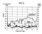
- the S/N ratio of the reception signal in the high frequency band is evaluated in the vehicle communication environment, as shown in Fig. 5, the notch attenuation can be observed at 1-2 MHz, around 7 MHz, around 12 MHz, and around 14 MHz. Moreover, at a frequency higher than 15 MHz, the noise level of a particular frequency is high.
- the notch attenuation is a signal attenuation caused in the vicinity of a particular frequency by a reflection at a branching point and a terminal point of the communication path
- the frequency at which the notch attenuation is caused is almost decided when the communication path layout is decided, i.e., when the branch structure in the communication path and the arrangement positions of the communication devices 2a, 2b, 2c, ... are decided.
- the communication capacity of the control system is comparatively small and a 2 MHz band is considered to be sufficient.
- the control device is controlled in the frequency band 2 MHz to 12 MHz and the information process is performed in the frequency band 12 MHz to 30 MHz.
- a carrier of the particular frequency may be affected when the OFDM (Orthogonal Frequency Division Multiplexing) as one of the multicast modulation methods is employed but communication can be performed with a carrier of other frequencies.
- OFDM Orthogonal Frequency Division Multiplexing
- the frequency band 2 MHz to 4 MHz (hereinafter, referred to as band A) is assigned to throttle control, a frequency band 5 MHz to 7 MHz (hereinafter, referred to as band B) is assigned to electric brake control, a frequency band 8 MHz to 10 MHz (hereinafter, referred to as band C) is assigned to steering control, and a frequency band 12 MHz to 30 MHz (hereinafter, referred to as band D) is assigned to the back view monitor and other information processing systems.
- the band 12 MHz to 30 MHz may be divided into a plurality of bands. The bandwidth of the divided band is decided by considering the capacity required for respective communications.
- the control system of a comparatively small communication capacity is divided into a plurality of frequency bands for communication and accordingly, it is possible to perform control with preferable control response.
- the frequency band 12 MHz to 30 MHz having a comparatively high S/N ratio is assigned to the information processing system requiring a large communication capacity, it is possible to perform a large-capacity communication such as image information.
- the information processing system not requiring a high-speed response may be communicated by time division.
- the band A is a frequency band of a carrier signal which is modulated and demodulated by the modulation unit 34 and the demodulation unit 27.
- the carriers of the band B and the band C are generated by frequency-converting, i.e., frequency-shifting the carrier signal of the base band by using the transmission carrier frequency conversion unit 31 which is a mixer circuit.
- the frequency shift amount is decided by the frequency of the reference wave signal supplied from the reference wave signal generation unit 33. In this case, when frequency shift is performed to the band B, the frequency of the reference wave signal is 3 MHz and when frequency shift is performed to the band C, the frequency of the reference wave signal is 6 MHz.
- the band D the base band is set to 12 to 30 MHz.
- the reception carrier frequency conversion unit 23 and the transmission carrier frequency conversion unit 31 are set so that their frequency conversion function will not work.
- the frequency of the reference wave signal generated by the reference wave signal generation unit 33 is selected by a band selection signal 28c outputted from the control unit 28.
- the reference wave signal generation unit 33 includes a generation circuit for generating a reference wave of 3 MHz and a generation circuit for generating a reference wave of 6 MHz.
- the band selection signal 28c selects which of the reference waves is to be outputted.
- reception carrier frequency conversion unit 23 and the transmission carrier frequency conversion unit 31 select a pass band of the band pass filter 21 in accordance with the frequency band after the frequency conversion of the carrier signal.
- the same band selection signal 28c as the signal inputted to the reference wave signal generation unit 33 is used as the selection signal of the pass band.
- each band is selected as has been described above, communication can be performed in a band avoiding a large notch attenuation in the vicinity of 1-2 MHz, 7 MHz, and 12 MHz.
- the band of 15 MHz to 25 MHz no notch attenuation exists and a high-quality communication, i.e., a high-speed communication can be performed.
- the frequency band where notch attenuation is caused depends on the communication path arrangement structure or the like and does not change frequently once the arrangement structure or the like is determined.
- the control unit 28 can select a band by the band selection signal 28c in accordance with actual states of the noise and the notch attenuation and use a carrier of the selected communication band to perform communication by selecting a band having a small noise and a small notch attenuation, thereby realizing a high-speed and high-quality communication.
- control unit 28 switches the frequency band to be used for communication while judging the quality of the communication path by measuring the S/N ratio of the reception signal and the reception data transmission error rate.
- the band selection signal 28c outputted from the control unit 28 may be fixed so as to use a frequency band where the noise and the notch attenuation are smallest if the noise and the notch attenuation do not change greatly.
- an input switch is arranged as an auxiliary unit of the control unit 28 and the band selection signal 28c is set by the ON/OFF state of the input switch.
- the input switch By arranging the input switch, different frequency bands can be set in the same communication device, thereby providing an advantage to rationalize the design process, development, and manufacturing.
- the noise level of a particular frequency higher than 15 MHz is high, explanation has been given on a case using the OFDM as the modulation/demodulation method.
- the carrier modulation/demodulation method it is also possible to use the ordinary multi-carrier modulation method, the multi-value modulation method allocating a plurality of waveforms having different amplitudes and phases to one carrier, or the multi-carrier multi-value modulation method combining the both methods.
- Fig. 6 shows the relationship between the S/N ratio and the communication error rate when the data allocation amount is made to be a parameter in the multi-value modulation method.
- BPSK stands for the binary phase shift keying method
- QPSK stands for the quadrature phase shift keying method
- QAM stands for the quadrature amplitude modulation method.
- the data allocation amount to the carrier is 1 bit (2-value) in the BPSK, 2 bits (4-value), 4 bits (16-value) in the 16 QAM, 6 bits (64-value) in the 64 QAM, and 8 bits (256-value) in the 256 QAM.
- the least S/N ratio required in the 256 QAM, 64 QAM, 16 QAM, QPSK, and BPSK are about 22.5 dB, about 17.7 dB, about 13.5 dB, about 9.5 dB, and about 6.3 dB, respectively.
- the data amount allocated to the carrier can be changed in accordance with the S/N ratio of the communication path. When the data allocation amount is reduced, the communication speed is lowered. On the contrary, when the data allocation amount is increased, the communication speed is increased. Accordingly, it is possible to perform communication at a communication speed according to the S/N ratio of the communication path.
- the transmission error rate can be reduced from 10 -5 to the order of 10 -7 .
- the communication speed is 1 Mbps
- one error occurs once in 10 seconds if viewed from probability.
- stable communication can be obtained.
- the carrier band is narrow as compared to the single-carrier multi-value modulation method. Accordingly, the S/N ratio in one carrier cannot be made large. However, even if the noise level in the vicinity of a particular frequency becomes large, only the data allocation amount to any one carrier is lowered and no affect to other carriers occurs. For this, in the multi-carrier modulation method, even if the noise level in the vicinity of a particular frequency has become large, it is possible to minimize the lowering of the communication speed as a whole.
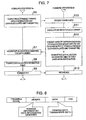
- Fig. 7 is a flowchart for performing the process for evaluating the S/N ratio of the communication path (also called training process).
- training data is communicated between the communication devices and an S/N ratio is calculated according to the received signal.
- the data allocation amount to the carrier is decided.
- the training process is started at a set time interval during a data transmission or reception between communication devices such as an interrupt of a timer in the communication device 2a and the control unit 28 of the communication device 2a outputs the training data prepared in advance to the modulation unit 34.
- the training data is modulated to a carrier and transmitted to the communication device 2b (step S6).
- the communication device 2d receives the training data (step S10) and calculates the S/N ratio for each of the carriers (step S11).
- a pair of a carrier number and a data allocation amount to be allocated to the carrier are converted into packet data and outputted to the modulation unit 34 (step S12).
- the pair of the carrier number and the data allocation amount will be referred to as data allocation information.
- step S12 the communication device 2d rewrites a data allocation information table owned by the control unit 28 and updates the data allocation information owned by itself.
- the data allocation information is used when demodulating the carrier transmitted from the communication device 2a, by the communication device 2d.
- the communication device 2a receives the data allocation information for each transmission wave transmitted from the communication device 2d (step S7) and rewrites the data allocation information table owned by the control unit 28 of the communication device 2a (step S8).
- the communication device 2a transmits an ACK (Acknowledge) message to the communication device 2d (step S9).
- ACK Acknowledge
- the communication device 2d receives the ACK message (step S13), thereby completing the process.
- the training data is transmitted from the communication device 2d to the communication device 2a and the S/N ratio from the communication device 2d to the communication device 2a is evaluated.
- the training process shown in Fig. 7 needs to be executed only once but when the S/N ratio is not symmetric, for example, when the noise source is at the communication device 2d and the noise of the communication device 2d is greater than the noise of the communication device 2a, the S/N ratio of the communication device 2d is smaller.
- the S/N ratio evaluation is performed in both directions and the obtained data allocation information is stored in the control unit 28 so as to be used upon modulation and demodulation.
- Fig. 8 shows a transmission format of a packet used for communication between the communication devices according to the present embodiment.
- the transmission format has a preamble signal, a header, data, and CRC.
- the header contains a training information/data information identifier indicating whether the transmitted data is training information or normal data information.
- training information training information
- training data is contained in the data.
- data information normal transmission data is contained in the data.
- the preamble is used for symbol synchronization and the CRC is used for checking a transmission data error.
- the header contains information for data information identification, i.e., ID information for identifying the communication device to which the data is to be transmitted.
- ID information identifies, for example, to which of the electric brakes 63, 64, 65, 66 the data is to be transmitted.
- training data data such as 256 QMM, 64 QAM, and QPSK are used.
- QPSK training data an example of QPSK training data will be given below.
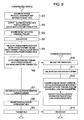
- Fig. 9 is a flowchart showing the procedure of the training process which is started by an event.
- the training process shown in Fig. 7 is started by an interrupt at a predetermined time interval by a timer or the like.
- the training process shown in Fig. 9 is started when a transmission error occurrence frequency within a set time exceeds a threshold value while normal communication is performed.
- step S1 to step S5 are processes performed in normal communication.
- Step S1 and step S2 are normal transmission processes.
- the control unit 28 of the communication device 2a acquires data to be transmitted from the protocol conversion unit 29, creates packet data (step S1), and outputs the created packet data to the modulation unit 34 (step S2).
- the packet data which has been modulated is subjected to the D/A conversion, the frequency conversion, and amplification, and transmitted via the communication path to the communication device 2d.
- Step S3 to step S5 are normal reception processes.
- the carrier transmitted from the communication device 2d is amplified and subjected to the frequency conversion and the A/D conversion, and equalized before being inputted to the demodulation unit 27 where it is demodulated.
- the control unit 28 of the communication device 2a acquires the demodulated packet data from the demodulation unit 27 (step S3) and evaluates the CRC (Cycle Redundancy Code Check) attached to the packet data so as to detect a transmission error (step S4).
- CRC Car Redundancy Code Check
- step S5 the error occurrence frequency within a set time (transmission error rate) is calculated (step S5) and if the calculated error occurrence frequency (transmission error rate) exceeds a predetermined threshold value, the training process of the procedure shown in Fig. 7 is executed in step S6 to step S13.
- the communication devices 2a and 2d perform normal data communication. In this case, the allocation of the data allocation amount for the carrier is performed according to the updated one.
- the training process started by the event that the transmission error rate is lowered is performed when the S/N ratio is degraded. Accordingly, as compared to the method evaluating the S/N ratio at every set time interval, the interrupt frequency is reduced, which provides an advantage that the efficiency of the communication data transmission is hardly lowered.
- the training process started by an event can be employed both of the training process started by an event and the training process started at a set time interval.
- the data allocation amount for the carrier can be updated when the S/N ratio is degraded but even if the S/N ratio is improved, it is impossible to return the state to the previous one by increasing the data allocation amount.
- the training process can be performed by a timer interrupt so that the data allocation amount for the carrier whose S/N ratio is improved is updated to a greater value. For this, when the S/N ratio is improved, it is possible to update the communication to a higher speed, thereby improving the transmission efficiency as a whole.
- the communication characteristic (such as a transmission error and the S/N ratio) of the communication path between the communication devices 2a, 2b, 2c is dynamically evaluated.
- the control unit 28 outputs information on the data allocation amounts 28a, 28b to the demodulation unit 27 and the modulation unit 34 and executes the modulation and demodulation processes (data allocation amount modification), thereby realizing a higher-speed and higher-quality communication with less transmission errors.
- the operation amount of the steering wheel 52 is detected by the steering angle sensor, inputted to the controller 55, and transmitted as a carrier of the frequency band of the band C via the communication device 2c to the battery line 1.
- the step-in amount of the throttle pedal is detected by the accelerator position sensor, inputted to the controller 53, and transmitted as a carrier of the frequency band of the band A via the communication device 2a to the battery line 1.
- the step-in amount of the brake pedal 51 is detected by a sensor, inputted to the controller 54, and transmitted as a carrier of the frequency band of band B via the communication device 2b to the battery line 1.
- An image captured by the back view monitor camera 56 is continuously inputted to the controller 57 and transmitted as a carrier of the frequency band of band D via the communication device 2k to the battery line 1.
- ID information for identifying the electric brake to be controlled is attached to the header of the packet data transmitted from the communication device 2b.
- the carrier of band C transmitted from the communication device 2c is received by the communication device 2e having the band pass filter 21 of the same frequency band and inputted to the controller 58.
- the controller 58 the signal of the speed sensor is fed back and the steering control signal based on the vehicle speed is outputted to the steering device 69.
- the operation of the steering wheel 52 is not transmitted via the mechanical steering transmission mechanism but the steering device 69 is controlled by communication via the battery line 1, the communication devices 2c, 2e. Accordingly, there is no need of providing a mechanical steering transmission mechanism, which in turn assures a sufficient space and increases the degree of freedom of arrangement of the steering device. Moreover, the control response is improved.
- the carrier of band A transmitted from the communication device 2a is received by the communication device 2d having the band pass filter 21 of the same frequency band and the control signal and accelerator position sensor detection value are inputted to the ECU 68 so as to control the engine.
- the carrier of band B transmitted from the communication device 2b is received by the communication devices 2f, 2g, 2h, 2i having the band pass filter 21 of the same frequency band.
- the controllers 59, 60, 61, 62 make judgment to perform control of the corresponding electric brakes by using the data received by the communication devices 2f, 2g, 2h, 2i.
- control can be performed by communication through the battery line having a large diameter up to the portion where the electric brake having a large vibration is installed, breakage hardly occurs.
- control signals or detection values of the steering wheel operation, the accelerator operation, and the brake operation are simultaneously transmitted by power line carriers for each of the frequency bands A, B, C and accordingly, it is possible to perform a control of preferable response.
- the configuration of the devices to be installed in the vehicle is simplified and the space inside the vehicle can be increased with a reduced number of cables to be installed. This reduces the weight of the entire vehicle and improves mileage.
- the carrier of band D transmitted from the communication device 2k is received by the communication device 2j having the band pass filter 21 of the same frequency band and displays an image at the rear of the vehicle by operation of the car navigation device 67.
- the training process is performed mutually, the S/N ratio is evaluated in the both directions, and the obtained data allocation information is used to perform data allocation for the carrier. This enables a high-quality communication with less transmission errors.
- the battery line is used to control the accelerator, the brake, and the steering wheel at the frequency bands obtained by dividing the frequency band 2 to 10 MHz with power line carrying for communication.
- the information processing system such as the back view monitor is communicated at the frequency band of 12 to 30 MHz with power line carrying. Accordingly, it is possible to perform control with a preferable control response without requiring installation of a special communication cable at the rear of the vehicle. Thus, it is possible to provide a vehicle and an in-vehicle communication control device which can be easily mounted with a communication cable of small weight.
Applications Claiming Priority (1)
| Application Number | Priority Date | Filing Date | Title |
|---|---|---|---|
| PCT/JP2005/009010 WO2006120757A1 (ja) | 2005-05-11 | 2005-05-11 | 自動車及び自動車内の通信、制御装置 |
Publications (2)
| Publication Number | Publication Date |
|---|---|
| EP1882613A1 true EP1882613A1 (de) | 2008-01-30 |
| EP1882613A4 EP1882613A4 (de) | 2010-01-06 |
Family
ID=37396279
Family Applications (1)
| Application Number | Title | Priority Date | Filing Date |
|---|---|---|---|
| EP05738574A Withdrawn EP1882613A4 (de) | 2005-05-11 | 2005-05-11 | Fahrzeug und fahrzeug-kommunikationssteuervorrichtung |
Country Status (5)
| Country | Link |
|---|---|
| US (1) | US20090306844A1 (de) |
| EP (1) | EP1882613A4 (de) |
| JP (1) | JPWO2006120757A1 (de) |
| CN (1) | CN101171153B (de) |
| WO (1) | WO2006120757A1 (de) |
Cited By (2)
| Publication number | Priority date | Publication date | Assignee | Title |
|---|---|---|---|---|
| WO2009036834A1 (de) * | 2007-09-22 | 2009-03-26 | Daimler Ag | Kraftfahrzeug |
| WO2013102516A1 (de) * | 2012-01-02 | 2013-07-11 | Robert Bosch Gmbh | Vorrichtung zur erfassung von analogen signalen sowie verfahren zum betreiben der vorrichtung |
Families Citing this family (16)
| Publication number | Priority date | Publication date | Assignee | Title |
|---|---|---|---|---|
| US8102779B2 (en) | 2008-10-31 | 2012-01-24 | Howard University | System and method of detecting and locating intermittent electrical faults in electrical systems |
| US8897635B2 (en) | 2008-10-31 | 2014-11-25 | Howard University | System and method of detecting and locating intermittent and other faults |
| US8711711B2 (en) | 2008-10-31 | 2014-04-29 | Howard University | System and method of detecting and locating intermittent and other faults |
| JP2012109943A (ja) * | 2010-10-27 | 2012-06-07 | Kyoto Univ | 電力線通信システム |
| JP2012206616A (ja) * | 2011-03-30 | 2012-10-25 | Furukawa Electric Co Ltd:The | 電線配策構造および電力線搬送通信ケーブル |
| JP5880548B2 (ja) * | 2011-04-28 | 2016-03-09 | 富士通株式会社 | データ割り当て方法およびデータ割り当てシステム |
| JP2012257122A (ja) * | 2011-06-09 | 2012-12-27 | Hitachi Automotive Systems Ltd | 車両制御装置、車両制御システム |
| JP5983168B2 (ja) * | 2012-08-09 | 2016-08-31 | 株式会社デンソー | フェールセーフ装置及びフェールセーフシステム |
| TWI514800B (zh) * | 2012-11-12 | 2015-12-21 | Wistron Neweb Corp | 電力線通訊系統及其控制方法 |
| JP5803983B2 (ja) | 2013-06-07 | 2015-11-04 | 株式会社デンソー | 通信装置 |
| JP6593550B2 (ja) * | 2016-11-10 | 2019-10-23 | 株式会社オートネットワーク技術研究所 | 車載通信システム |
| US11641628B2 (en) * | 2017-06-15 | 2023-05-02 | Panasonic Intellectual Property Corporation Of America | Terminal and communication method |
| JP7025188B2 (ja) * | 2017-12-04 | 2022-02-24 | 矢崎総業株式会社 | 車両用の回路体、及び、車両用の回路体の製造方法 |
| JP7052557B2 (ja) * | 2018-05-22 | 2022-04-12 | コベルコ建機株式会社 | 遠隔操作システム |
| WO2020158723A1 (ja) * | 2019-01-31 | 2020-08-06 | 住友電気工業株式会社 | 車載通信システムおよび車載用ケーブル |
| DE102020116863A1 (de) * | 2020-06-26 | 2021-12-30 | Thyssenkrupp Ag | Sensoranordnung |
Citations (3)
| Publication number | Priority date | Publication date | Assignee | Title |
|---|---|---|---|---|
| WO2002005450A1 (fr) * | 2000-07-12 | 2002-01-17 | Schlumberger Industries S.A. | Procede de reception d'un signal transmis par l'intermediaire du reseau electrique et dispositif pour sa mise en oeuvre |
| US20030052771A1 (en) * | 2001-08-31 | 2003-03-20 | Thorsten Enders | Supply line structure for transmitting information between motor-vehicle components |
| EP1475901A1 (de) * | 2002-02-13 | 2004-11-10 | SUMITOMO ELECTRIC INDUSTRIES Ltd | Kommunikationsmodem für stromleitungsträger |
Family Cites Families (20)
| Publication number | Priority date | Publication date | Assignee | Title |
|---|---|---|---|---|
| JPS62284476A (ja) * | 1986-06-02 | 1987-12-10 | Fujitsu Ltd | デ−タ収集装置 |
| FR2726411B1 (fr) * | 1994-10-26 | 1997-01-17 | Peugeot | Systeme de communication d'informations par courants porteurs, notamment pour un vehicule automobile |
| JPH0955986A (ja) | 1995-08-15 | 1997-02-25 | Omron Corp | 車内通信システム |
| JPH11266251A (ja) | 1998-03-16 | 1999-09-28 | Harness Syst Tech Res Ltd | 車両内配線装置 |
| DE10107385A1 (de) * | 2001-02-16 | 2002-09-05 | Harman Audio Electronic Sys | Vorrichtung zum geräuschabhängigen Einstellen der Lautstärken |
| JP2003046453A (ja) * | 2001-07-31 | 2003-02-14 | Denso Corp | 電源ic |
| JP2003116187A (ja) | 2001-10-04 | 2003-04-18 | Yokohama Rubber Co Ltd:The | 電力供給を兼ねた車内lanシステム |
| JP3896891B2 (ja) | 2002-04-25 | 2007-03-22 | 株式会社デンソー | 車両通信システム |
| DE10248456A1 (de) * | 2001-10-19 | 2003-06-18 | Denso Corp | Fahrzeugkommunikationssystem |
| JP3622726B2 (ja) * | 2002-01-09 | 2005-02-23 | 三菱電機株式会社 | 高度道路交通システムの狭域通信用車載器 |
| JP3749483B2 (ja) * | 2002-01-11 | 2006-03-01 | トヨタ自動車株式会社 | 駐車支援装置 |
| JP2004096600A (ja) * | 2002-09-03 | 2004-03-25 | Yazaki Corp | 車両用電源重畳多重通信装置 |
| DE10340431B4 (de) * | 2002-09-03 | 2008-04-10 | Yazaki Corp. | Energieversorgungsleitungs-Kommunikationseinrichtung für ein Fahrzeug |
| JP2004096601A (ja) * | 2002-09-03 | 2004-03-25 | Yazaki Corp | 車両用電源重畳多重通信装置 |
| JP2004155395A (ja) * | 2002-11-08 | 2004-06-03 | Denso Corp | 車両周辺画像処理装置 |
| JP4442092B2 (ja) * | 2002-12-24 | 2010-03-31 | アイシン精機株式会社 | 車両の運動制御装置 |
| JP3874352B2 (ja) * | 2003-01-28 | 2007-01-31 | 株式会社日立製作所 | 列車内通信システム及び列車内通信装置 |
| JP2005014856A (ja) * | 2003-06-30 | 2005-01-20 | Yuasa Corp | 自動車内信号伝送装置及び信号伝送方法 |
| JP2005076831A (ja) * | 2003-09-02 | 2005-03-24 | Sumitomo Electric Ind Ltd | 緊急制動システム及びブレーキ制御装置 |
| US7352281B2 (en) * | 2005-02-22 | 2008-04-01 | Instrument Systems Inc. | Automotive gauge system using a power line carrier |
-
2005
- 2005-05-11 US US11/913,968 patent/US20090306844A1/en not_active Abandoned
- 2005-05-11 JP JP2007526742A patent/JPWO2006120757A1/ja active Pending
- 2005-05-11 CN CN2005800497193A patent/CN101171153B/zh not_active Expired - Fee Related
- 2005-05-11 WO PCT/JP2005/009010 patent/WO2006120757A1/ja not_active Application Discontinuation
- 2005-05-11 EP EP05738574A patent/EP1882613A4/de not_active Withdrawn
Patent Citations (3)
| Publication number | Priority date | Publication date | Assignee | Title |
|---|---|---|---|---|
| WO2002005450A1 (fr) * | 2000-07-12 | 2002-01-17 | Schlumberger Industries S.A. | Procede de reception d'un signal transmis par l'intermediaire du reseau electrique et dispositif pour sa mise en oeuvre |
| US20030052771A1 (en) * | 2001-08-31 | 2003-03-20 | Thorsten Enders | Supply line structure for transmitting information between motor-vehicle components |
| EP1475901A1 (de) * | 2002-02-13 | 2004-11-10 | SUMITOMO ELECTRIC INDUSTRIES Ltd | Kommunikationsmodem für stromleitungsträger |
Non-Patent Citations (1)
| Title |
|---|
| See also references of WO2006120757A1 * |
Cited By (2)
| Publication number | Priority date | Publication date | Assignee | Title |
|---|---|---|---|---|
| WO2009036834A1 (de) * | 2007-09-22 | 2009-03-26 | Daimler Ag | Kraftfahrzeug |
| WO2013102516A1 (de) * | 2012-01-02 | 2013-07-11 | Robert Bosch Gmbh | Vorrichtung zur erfassung von analogen signalen sowie verfahren zum betreiben der vorrichtung |
Also Published As
| Publication number | Publication date |
|---|---|
| CN101171153A (zh) | 2008-04-30 |
| CN101171153B (zh) | 2010-05-12 |
| JPWO2006120757A1 (ja) | 2008-12-18 |
| EP1882613A4 (de) | 2010-01-06 |
| US20090306844A1 (en) | 2009-12-10 |
| WO2006120757A1 (ja) | 2006-11-16 |
Similar Documents
| Publication | Publication Date | Title |
|---|---|---|
| EP1882613A1 (de) | Fahrzeug und fahrzeug-kommunikationssteuervorrichtung | |
| US7760815B2 (en) | Apparatus and method for transmission/reception | |
| US20140022892A1 (en) | Data communications system and method of data transmission | |
| JP4575898B2 (ja) | 列車内通信システム及び列車内通信方法 | |
| EP0720792A1 (de) | Verfahren und anordnung zur selektiv eingeschalteten diversitysignalisierung in einem funkkommunikationssystem | |
| JP2004096602A (ja) | 車両用電源重畳多重通信装置の中継器 | |
| US20180108961A1 (en) | Shared use of a motor vehicle antenna by an e-call controller | |
| JP2010041376A (ja) | 鉄道車両内情報ネットワーク装置 | |
| US7394781B2 (en) | Wireless remote controller using time division protocol and satellite radio receiver including the same | |
| US11139900B2 (en) | Vehicle-to-X communication system | |
| JP2007237781A (ja) | タイヤ空気圧監視システム | |
| JP4050565B2 (ja) | 列車無線通信システム | |
| US10162782B2 (en) | Data communications system and method of data transmission | |
| JP4893413B2 (ja) | 列車内通信装置 | |
| US20100246694A1 (en) | Integrated reception system | |
| JP2005269416A (ja) | 通信装置および通信システム | |
| JP4532168B2 (ja) | 狭域通信装置の固定局 | |
| JP5055955B2 (ja) | 鉄道車両用伝送装置 | |
| JP2007258805A (ja) | 受信機、ノイズ除去方法、及び、受信ユニット | |
| JP2007221614A (ja) | 自動車内通信装置 | |
| JP2006339821A (ja) | 電力線通信システム及び電力線通信用のデータ受信装置並びに電力線通信方法 | |
| JP3918669B2 (ja) | 車載無線通信装置 | |
| JP2008258875A (ja) | 車両内情報通信ネットワーク | |
| JP2005269513A (ja) | 車両用変復調システム、受信装置および送信装置 | |
| CN113365880A (zh) | 车载通信系统及车载用电缆 |
Legal Events
| Date | Code | Title | Description |
|---|---|---|---|
| PUAI | Public reference made under article 153(3) epc to a published international application that has entered the european phase |
Free format text: ORIGINAL CODE: 0009012 |
|
| 17P | Request for examination filed |
Effective date: 20071211 |
|
| AK | Designated contracting states |
Kind code of ref document: A1 Designated state(s): AT BE BG CH CY CZ DE DK EE ES FI FR GB GR HU IE IS IT LI LT LU MC NL PL PT RO SE SI SK TR |
|
| DAX | Request for extension of the european patent (deleted) | ||
| A4 | Supplementary search report drawn up and despatched |
Effective date: 20091204 |
|
| STAA | Information on the status of an ep patent application or granted ep patent |
Free format text: STATUS: THE APPLICATION HAS BEEN WITHDRAWN |
|
| 18W | Application withdrawn |
Effective date: 20120210 |