EP1882395B1 - Method and system for lighting control - Google Patents
Method and system for lighting control Download PDFInfo
- Publication number
- EP1882395B1 EP1882395B1 EP06727983.6A EP06727983A EP1882395B1 EP 1882395 B1 EP1882395 B1 EP 1882395B1 EP 06727983 A EP06727983 A EP 06727983A EP 1882395 B1 EP1882395 B1 EP 1882395B1
- Authority
- EP
- European Patent Office
- Prior art keywords
- control device
- lighting
- light
- received
- user
- Prior art date
- Legal status (The legal status is an assumption and is not a legal conclusion. Google has not performed a legal analysis and makes no representation as to the accuracy of the status listed.)
- Active
Links
Images
Classifications
-
- H—ELECTRICITY
- H05—ELECTRIC TECHNIQUES NOT OTHERWISE PROVIDED FOR
- H05B—ELECTRIC HEATING; ELECTRIC LIGHT SOURCES NOT OTHERWISE PROVIDED FOR; CIRCUIT ARRANGEMENTS FOR ELECTRIC LIGHT SOURCES, IN GENERAL
- H05B47/00—Circuit arrangements for operating light sources in general, i.e. where the type of light source is not relevant
- H05B47/10—Controlling the light source
- H05B47/155—Coordinated control of two or more light sources
-
- H—ELECTRICITY
- H05—ELECTRIC TECHNIQUES NOT OTHERWISE PROVIDED FOR
- H05B—ELECTRIC HEATING; ELECTRIC LIGHT SOURCES NOT OTHERWISE PROVIDED FOR; CIRCUIT ARRANGEMENTS FOR ELECTRIC LIGHT SOURCES, IN GENERAL
- H05B47/00—Circuit arrangements for operating light sources in general, i.e. where the type of light source is not relevant
- H05B47/10—Controlling the light source
- H05B47/175—Controlling the light source by remote control
- H05B47/19—Controlling the light source by remote control via wireless transmission
-
- H—ELECTRICITY
- H05—ELECTRIC TECHNIQUES NOT OTHERWISE PROVIDED FOR
- H05B—ELECTRIC HEATING; ELECTRIC LIGHT SOURCES NOT OTHERWISE PROVIDED FOR; CIRCUIT ARRANGEMENTS FOR ELECTRIC LIGHT SOURCES, IN GENERAL
- H05B47/00—Circuit arrangements for operating light sources in general, i.e. where the type of light source is not relevant
- H05B47/10—Controlling the light source
- H05B47/175—Controlling the light source by remote control
- H05B47/196—Controlling the light source by remote control characterised by user interface arrangements
-
- H—ELECTRICITY
- H05—ELECTRIC TECHNIQUES NOT OTHERWISE PROVIDED FOR
- H05B—ELECTRIC HEATING; ELECTRIC LIGHT SOURCES NOT OTHERWISE PROVIDED FOR; CIRCUIT ARRANGEMENTS FOR ELECTRIC LIGHT SOURCES, IN GENERAL
- H05B47/00—Circuit arrangements for operating light sources in general, i.e. where the type of light source is not relevant
- H05B47/10—Controlling the light source
- H05B47/175—Controlling the light source by remote control
- H05B47/198—Grouping of control procedures or address assignation to light sources
Definitions
- the present invention relates in general to a method and device for controlling a lighting system comprising a plurality of light sources.
- the invention relates particularly to a method for controlling a lighting system and such a system as described in the preambles of claim 1 and 5 respectively.
- WO 2004/057927 discloses a method for configuration a wireless controlled lighting system.
- the prior art system comprises a central master control device, several local control master devices, which are linked to the central master device, and, associated with each local control master device, one or more lighting units and a portable remote control.
- Each lighting unit and the portable control are linked to their associated local control master device by a wireless connection.
- Light emitted by a lighting unit is modulated by an identification code, which was stored in the lighting unit before controlling the lighting unit.
- the portable control is suitable to receive the modulated light and to derive therefrom the identification code of the source lighting device.
- the portable control has an user interface by which an user can enter additional data, which is sent to its associated local control master device together with the identification code received from a lighting unit.
- Said additional data may contain an indication of a switch or key which the user assigns to the lighting unit to operate the lighting unit from then on, such as for turning on or off. Then, the data is communicated to the central master device for general lighting
- WO 02/13490 discloses methods and systems for automatic configuration of network devices, in particular illumination devices.
- illumination devices may include LED-based lights that can be used to transmit data.
- a light may be automatically configured through the transmission of a unique identity number or code.
- a second device possibly handheld can receive the sequence and include the capability of uniquely accessing that light and adjust its settings.
- the control of lighting units is carried out by forward control only, that is, without any kind of feedback about actual lighting conditions and locations of the lighting units.
- an object can be illuminated by any number of lighting units directly, but also indirectly as a result of reflections.
- the prior art system it is not possible to measure lighting effects caused by different lighting units on an object and to change controlling of the lighting units dependent on the measured lighting effects.
- the above object of the invention is achieved by a method as described in claim 1.
- the location data can be obtained in a variety of manners which are well known by a person skilled in this art.
- the main control device may track the user control device while obtaining data about a light effect it caused at said location.
- the main control device is able to learn about light effects it causes at any location covered by the lighting arrangements by any combination of control commands it supplies to the lighting arrangements.
- the main control device will be able to track a movement of the user control device.
- the main control device will then be able to maintain a specific light effect it caused at any location of the user control device, when the user control device is moving or not.
- the main control device may apply any combination of control commands it finds suitable to maintain the lighting effect.
- the user will not have to worry or even care about it and he may, for example, pay all his attention to create and to achieve a lighting scheme.
- the above object of the invention is also achieved by a lighting system as described in claim 5.
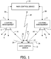
- the system shown in Fig. 1 comprises one or more lighting arrangements 2, which may each comprise one or more lighting units, each lighting unit being schematically indicated by reference numeral 4.
- Lighting units 4 associated with a lighting arrangement 2 may be arranged at different locations in a room or in some other area to be lighted. Light emitted by a lighting unit 4 is indicated by a group of dashed arrows 6.
- a lighting arrangement 2 comprises means, for storing an identification code, which is unique for the lighting arrangement 2, control means for supplying the lighting unit 4, and means for modulating the supply of a lighting unit 4 and therewith modulating the light output of the lighting unit 4, dependent on data, which at least comprises said identification code.
- the system shown in Fig. 1 further comprises a main control device 10 and an user control device 12.
- the user control device 12 is a hand held device, which is portable by a user.
- the user control device is provided with light sensing means, of which a light entrance dome 14 is shown only, which is suitable to receive light from its environment, that is, from one or more lighting units 4, either directly or indirectly after reflection on objects such as walls.
- Arrows 16 and 18 indicate light which the user control device 12 receives from different lighting units 4.
- Arrows 20-26 indicate light which is received by the user control device 12 from other lighting units 4 and/or other sources, possibly by reflection.
- the user control device 12 can communicate with the main control device 10 via a wireless connection, which is indicated by reference numeral 28.
- Each lighting arrangement 2 is connected to the main control device 10 via a link 30, which can be of any type.
- the main control device 10 contains a processor, which runs a control program in concordance with a scheme for lighting locations covered by the lighting units 4 of the lighting arrangements 2, such as for light intensity, light color range and light direction.
- the program uses data, which is obtained about such locations a priori while using the user control device 12 by a user.
- the user uses the user control device 12 to receive light at each of said locations from any lighting arrangement 2 covering the location, deriving an identification code, of a single lighting arrangement 2 or, in case of receiving composite direct or indirect light from several lighting arrangements 2, several identification codes originating from respective lighting arrangements 2.
- the user control device measures some property of the received light of interest, apart from representing data, such as average light intensity during some interval. Then, the user control device 12 transmits data, which represents a value of a measured light property together with one or more derived identification codes, to the main control device 10.
- the program of the main control device 10 can determine the influence or effect a specific control of the main control device 10 has on the lighting at the current location of the user control device 12. Having gained data on several locations, the main control device 10 can control the lighting arrangements 2 in several ways to obtain wanted light effects in some or all of said locations.
- means for modulating light from a lighting device by data in particular an identification code
- means for receiving such modulated light and deriving the data therefrom is known per se, for example as disclosed by WO 2004/057927 and US 6,333,605 . Therefore such means, and other means, which are well known to a skilled person have not been shown and described in detail.
- a program and lighting scheme will be dependent on their application, such as for overall lighting exhibition halls, specific lighting objects in exhibition halls and lighting other rooms and areas where specific lighting effects are wanted. Therefore such a program and a lighting scheme have not been discussed in detail.
- the data which a lighting arrangement 2 uses to modulate light may comprise data about properties or specifications of the lighting arrangement 2.
- This additional data can be relayed through the user control device 12 together with the identification code of the lighting arrangement 2 to the main control device 10. Then, the main control device 10 can take said additional data in account when controlling the operation of said lighting arrangement 2 or lighting arrangements 2.
- Said additional data may refer to capacities about color dependent light intensities, and light directional information.
- the system as described above it is for instance possible, at any location within a large space illuminated by a plurality of light sources, such as for instance a shop, to locally dim the light intensity, without the user needing to know which of the light sources actually is illuminating that specific location.
- the user places the user control device 12 at the location of interest (or directs a light receiver of the user control device 12 to the location of interest) and actuates a button corresponding to the command "dim".
- the user control device 12 receives the light from the corresponding light source or light sources, derives the corresponding identification code(s), and transmits this code(s) to the main control device 10 together with a command signal "dim".
- the main control device 10 then knows which light sources are to be dimmed.
- the user may for instance set a color temperature.
- the light sources are LEDs
- LEDs can be switched ON and OFF very quickly, so a LED obeys a controlling modulation signal very well: a modulation at a high modulation frequency and a modulation depth of 100% is easily possible.
- the light sources are different types of lamps, such as for instance HID lamps, halogen lamps, etc
- modulating the light output with an identification code is more problematic.
- Such lamps do not switch ON and OFF so fast, so the modulation frequency should be reduced. Further, if such lamps are switched OFF, it may become difficult to re-ignite such lamps reliably and predictably.
- the system as described above relies on the presence of a main control device 10. Adding a light source to the system may be problematic for an average user, because the identification code of the new light source must be communicated to the main control device.
- each light source is provided with a dedicated light sensor, arranged to receive light only, or at least substantially only, from that specific light source.
- An output signal of this dedicated light sensor thus represents the actual intensity of the light emitted by that specific light source.
- the user control device emits a signal that represents the light as received by the user control device, supplemented by a command signal.
- the system comprises a correlator which receives the signals emitted by the user control device as well as the output signal of the dedicated light sensor of at least one light source.
- the correlator performs a correlation operation between the received signals, for instance on the basis of Fourier analysis, as is known per se so it is not necessary to explain correlation operations in greater detail here.
- the correlator determines how much a certain light source contributes to the light as received by the user control device.
- a certain light source responds to the user command only of its contribution to the light as received by the user control device is above a certain threshold.
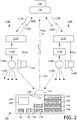
- Fig. 2 schematically shows a lighting system 100, comprising a plurality of lighting assemblies 110, each lighting assembly 110 comprising a controller 111, a ballast 112, and a lamp 113 (for instance a HID lamp) emitting light 114.
- Individual lighting assemblies and their components are indicated by the same reference numerals yet distinguished by an added character A, B, C, etc.
- the figure shows two lighting assemblies 110A and 110B, but a practical embodiment may easily comprise more than ten lighting assemblies.
- Each lighting assembly 110 further comprises a dedicated light sensor 115, which is arranged in such a way that, for practical purposes, it only receives light from the corresponding lamp 113.
- the light sensor 115 may comprise a photo diode or photo transistor.
- the dedicated light sensor 115 provides its output signal S LS to the controller 111.
- the controller 111 communicates the received sensor signal to a main control device 130. More particularly, the controller 111 emits a signal representing the light intensity as received by the sensor 115, and thus representing the intensity of the light 114 as emitted by the light source 113, which controller output signal will hereinafter be indicated as assembly-emitted light signal S AEL .
- the lighting system 100 further comprises a user control device 120, which has a light sensor (schematically represented at 121) receiving light 114 from potentially a plurality of lamps 113, depending on the location and direction of the light sensor 121.
- the user control device 120 has transmission facilities for communication with the main control device 130, as illustrated by arrow 122.
- the user control device 120 emits a first signal representing the intensity of the light 114 as received by its light sensor 121, which signal hereinafter will be indicated as user-received light signal S URL , and the user control device 120 emits a second signal representing the user command, which signal hereinafter will be indicated as command signal S C .
- the light 114 emitted by a light source 113 will exhibit a temporal variation that is unique for that specific light source, and which can be considered as a "fingerprint".
- the temporal variation may be provided by a deliberate modulation with an identification code, in which case the fact that the modulation depth may be less than 100% is not a problem any more.
- the temporal variation may also be provided by a deliberate modulation with a regular signal that does not contain an identification code, for instance a brief interruption at a certain frequency.
- the light output will have frequency components caused by the normal operation of the ballast.
- Such lamps are typically operated with a commutating direct current: the commutation frequency will leave a characteristic "fingerprint" in the current waveform and hence the emitted light as a function of time: the commutation frequencies of individual free-running commutators will always differ from each other, even if only slightly. Further, each individual lamp will show a characteristic light output behavior on commutation.
- the lamp current is typically generated by a high-frequency converter, resulting in a characteristic high-frequency ripple on the lamp current and hence a characteristic high-frequency ripple in the output light: the converter frequencies of individual free-running high-frequency converters will always differ from each other, even if only slightly.
- the main control device 130 comprises a correlator 131 that is capable of correlating the user-received light signal S URL (representing the mixed light as received by the user control device 120) and the assembly-emitted light signals S AEL (representing the amount of light as emitted by the individual light sources 113 and thus representing the "fingerprint") and, as a result of the correlation operation, to provide correlation coefficients X A , X B , X C , etc, which indicate the quantitative contribution of the respective light sources 113A, 113B, 113C to the mixed light as received by the user control device 120.
- the summation of all correlation coefficients X A , X B , X C , etc, will ideally be equal to 100%, or less in case daylight or "strange" light sources contribute to the mixed light as received by the user control device 120.
- the main control device 130 Based on the correlation coefficients X A , X B , X C , etc, provided by the correlator 131, the main control device 130, using pre-programmed decision schemes, determines which lamps 113A, 113B, 113C etc are to respond to the command signal S C . In a possible embodiment, the main control device 130 selects the one lamp corresponding to the largest correlation coefficient. In another possible embodiment, the main control device 130 compares the correlation coefficients X A , X B , X C , etc, with a predetermined threshold X TH , for instance 50%, and selects all lamps of which the corresponding correlation coefficient is above said threshold X TH .
- a predetermined threshold X TH for instance 50%
- the main control device 130 may reduce the threshold X TH in subsequent steps, for instance 40%, 30%, 20%, until one or more correlation coefficients above the reduced threshold are found. After making such selection, the main control device 130 sends the required corresponding command signal to the controllers 111 corresponding to the selected lamps 113 (communication link 117). On receiving a command signal from the main control device 130, an individual controller 111 controls the ballast 212 in a corresponding manner.
- the user wishes to dim the light at a certain spot.
- the command signal S C contains the command "reduce illumination level”.
- the main control device 130 determines which lamps are to be controlled because they contribute to the illumination at the specific spot, and sends to these lamps the command "reduce lamp current”.
- the user wishes to change the color of the light (color temperature) at a certain spot.
- the command signal S C contains the command "more red”.
- the main control device 130 determines which lamps are to be controlled because they contribute to the illumination at the specific spot, and sends to these lamps the command "increase lamp current” or “reduce lamp current”, depending on whether such lamp contributes red light or not.
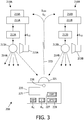
- Fig. 3 schematically shows another embodiment of a lighting system 200 according to the present invention.
- the user control device 220 has transmission facilities for emitting a user-received light signal S URL and a command signal S C , as illustrated by arrow 223.
- An important feature of this embodiment 200 is that it does not have a central main control device 130. Instead, each individual controller 211 itself receives and processes the signals from the user control device 220, and to that end each individual controller 211 is provided with a correlator 218.
- correlator 218 is similar as the operation of the correlator 131 described above, and it is not necessary to repeat the explanation of the operation in great detail.
- the main difference with the embodiment of Fig. 2 is that a correlator 218, apart from the user-received light signal S URL (received from the user control device 220), only receives the sensor output signal S LS from the corresponding sensor 215 of the same assembly 210, which sensor signal S LS represents the amount of light as emitted by the corresponding light source 213 and thus represents the "fingerprint") of the light source 213 of the same assembly 210.
- the correlator 218 is capable of correlating these two signals and, as a result of the correlation operation, to provide a correlation coefficient X which indicates the quantitative contribution of the corresponding light source 213 to the mixed light as received by the user control device 220.
- each individual controller 211 receives information (correlation coefficient X) as to how much its corresponding light source 213 contributes.
- the individual controller 211 Based on this correlation coefficient X provided by the correlator 218, the individual controller 211, using pre-programmed decision schemes, determines whether or not it should respond to the command signal S C . In a possible embodiment, the individual controller 211 compares the correlation coefficient X with a predetermined threshold X TH , for instance 50%, and decides to respond to the command signal S C if the correlation coefficient X is above said threshold X TH . After making a positive decision, the individual controller 211 controls the ballast 212 in a manner corresponding to the command signal S C .
- a predetermined threshold X TH for instance 50%
- the user wishes to dim the light at a certain spot.
- the command signal S C contains the command "reduce illumination level".
- Each individual controller 211 independently, determines whether it should respond because its corresponding lamp provides a substantial contribution to the illumination at the specific spot, and if yes, it controls the ballast 212 such as to reduce the lamp current.
- the above-described principle of correlation is used in making a decision whether a specific lamp should be selected for following a user command.
- the main controller centrally decides which lamps do and which lamps do not respond.
- each controller decides whether its lamp should or should not respond.
- the user control device 120, 220 may be designed to generate the user command signal S C as long as the user actuates a corresponding command button B C ; in such a case, the user keeps the command button B C depressed until he is satisfied with the result, then he releases the command button B C and the user command signal S C stops.
- the figures illustrate only one command button B C for the exemplary command function "dim", but it should be clear that the user control device 120, 220 may have multiple command buttons.
- the user control device 120, 220 comprises a memory 125, 225 with one or more predetermined lighting settings, and one or more selection buttons B S for selecting a specific one of the predetermined lighting settings.
- the user needs to actuate such selection buttons B S only once: it is not necessary to keep the button B S depressed.
- the user control device 120, 220 generates the appropriate user command signal S C while monitoring the setting of the mixed light 114 as received by its sensor 121, 221, until it finds that the actual light setting (within a predetermined tolerance limit) corresponds to the selected setting, and then it stops generating the user command signal S C .
- the user control device 120, 220 is provided with a signaling device 126, 226, for instance a LED, actuated by the user control device 120, 220 when the actual light setting corresponds to the selected setting so that the user knows that he is ready.
- a signaling device 126, 226, for instance a LED for instance a LED
- the figures illustrate only one selection button B S for selecting the exemplary setting "1", but it should be clear that the user control device 120, 220 may have multiple selection buttons.
- a setting in the memory 125, 225 can be a fixed, predetermined setting.
- the user control device 120, 220 is capable of adding settings to the memory, specifically by "reading” the actual settings. In a further elaboration of the invention, this makes it easily possible to copy the lighting conditions of one location and apply these lighting conditions to a different location.
- the user control device 120, 220 comprises the memory 125, 225.
- the user control device 120, 220 further comprises a command button 127, 227 for the function "copy” and a command button 128, 228 for the function "apply”.
- the user control device 120, 220 When the user actuates the command button "copy", the user control device 120, 220 stores the actual light settings prevailing at that specific moment and at that specific location into its memory 125, 225. The user may then go to a different location and actuate the command button "apply”. In response, the control device 120, 220 generates the appropriate user command signal S C while monitoring the setting of the mixed light 114 as received by its sensor 121, 221, until it that the actual light setting (within a predetermined tolerance limit) corresponds to the selected setting in its memory, and then it stops generating the user command signal S C . For a user, this is a very easy and intuitive manner of copying lighting settings, comparable to "copy and paste" in computer programs.
- the invention has been described in the context of examples where the decision whether a certain lamp should respond to a user command signal is made (centrally or individually) while that command signal is being sent. Lamps only respond if they substantially contribute to the light received at the location being controlled. Such embodiments are useful in cases where it is desired to control local lighting conditions, for instance the illumination of one object. There are, however, practical situations where it is desirable to control lighting conditions in a larger area, for instance an entire department in a store floor. That area may be one contiguous area or a set of multiple individual areas. As an example, in a clothes shop it may be desirable to control lighting in a ladies' department, men's department, children's department, etc. Further, with time, the extent of these departments may be changed.
- the present invention provides an easy way for grouping lamp assemblies together and controlling all assemblies of the same group at the same time.
- the user control device 120 comprises a command button 141 for the function "define group”, a command button 143 for the function "complete group”, and a command button 144 for the function "control group”.
- the main control device 130 enters a "define group” mode.
- the user now takes the user control device 120 to a location within, for instance, the ladies' department, and actuates a button of user control device 120.
- a button of user control device 120 Such button may be the same "define group” command button, but preferably is a different "add to group” command button 142.
- the main control device 130 determines which lamps substantially contribute to the illumination at that specific location. However, instead of issuing a command signal for those lamps, the main control device 130 enters those lamps into a group list in its associated memory 125.
- this grouping procedure can be performed on the basis of lamp recognition through correlation or on the basis of lamp recognition through receiving lamp identification codes.
- the main control device 130 When the user actuates the "control group” command button 144, the main control device 130 enters a "control group” mode, in which the main control device 130 will issue command signals to all lamp members belonging to the same group.
- the operation is similar as described above: when the user actuates a command button B C , for instance "dim lights", the main control device 130 determines which lamps substantially contribute to the illumination at that specific location, as explained earlier. However, instead of issuing a command signal for those lamps only, the main control device 130 checks its memory to find the group of which those lamps are members. Having found the group, the main control device 130 issues a command signal to all lamps belonging to this group.
- this includes lamps that are relatively remote from the current location of the user control device 120 so that they do not significantly contribute to the illumination at the current location of the user control device 120. Further, it should be clear that the user can control the entire group from any location where the group members significantly contribute to the illumination.
- the user control device 120 may have a signaling device such as a LED for signaling that it is operating in group control mode.
- the user control device 120 may further have a command button for exiting the group control mode.
Landscapes
- Engineering & Computer Science (AREA)
- Computer Networks & Wireless Communication (AREA)
- Circuit Arrangement For Electric Light Sources In General (AREA)
- Arrangement Of Elements, Cooling, Sealing, Or The Like Of Lighting Devices (AREA)
Priority Applications (1)
| Application Number | Priority Date | Filing Date | Title |
|---|---|---|---|
| EP06727983.6A EP1882395B1 (en) | 2005-04-22 | 2006-04-20 | Method and system for lighting control |
Applications Claiming Priority (3)
| Application Number | Priority Date | Filing Date | Title |
|---|---|---|---|
| EP05103279 | 2005-04-22 | ||
| EP06727983.6A EP1882395B1 (en) | 2005-04-22 | 2006-04-20 | Method and system for lighting control |
| PCT/IB2006/051223 WO2006111934A1 (en) | 2005-04-22 | 2006-04-20 | Method and system for lighting control |
Publications (2)
| Publication Number | Publication Date |
|---|---|
| EP1882395A1 EP1882395A1 (en) | 2008-01-30 |
| EP1882395B1 true EP1882395B1 (en) | 2019-06-19 |
Family
ID=36691435
Family Applications (1)
| Application Number | Title | Priority Date | Filing Date |
|---|---|---|---|
| EP06727983.6A Active EP1882395B1 (en) | 2005-04-22 | 2006-04-20 | Method and system for lighting control |
Country Status (5)
| Country | Link |
|---|---|
| US (1) | US8093817B2 (enExample) |
| EP (1) | EP1882395B1 (enExample) |
| JP (1) | JP5030943B2 (enExample) |
| CN (1) | CN101164381B (enExample) |
| WO (1) | WO2006111934A1 (enExample) |
Families Citing this family (105)
| Publication number | Priority date | Publication date | Assignee | Title |
|---|---|---|---|---|
| US7710271B2 (en) * | 2005-04-22 | 2010-05-04 | Koninklijke Philips Electronics N.V. | Method and system for lighting control |
| JP5129747B2 (ja) * | 2005-08-10 | 2013-01-30 | コーニンクレッカ フィリップス エレクトロニクス エヌ ヴィ | 照明機器の選択制御 |
| EP1821580A3 (de) * | 2006-02-21 | 2011-03-16 | Patent-Treuhand-Gesellschaft für elektrische Glühlampen mbH | Elektronisches Vorschaltgerät zur Lampenstrommodulation |
| WO2007099318A1 (en) * | 2006-03-01 | 2007-09-07 | The University Of Lancaster | Method and apparatus for signal presentation |
| CN101438624B (zh) * | 2006-05-03 | 2010-11-03 | 皇家飞利浦电子股份有限公司 | 使用光波标识的照明拷贝和粘贴操作 |
| EP2084943A2 (en) * | 2006-10-18 | 2009-08-05 | AMBX UK Limited | Method and system for detecting effect of lighting device |
| ATE474439T1 (de) | 2006-10-27 | 2010-07-15 | Koninkl Philips Electronics Nv | Farbgesteuerte lichtquelle und verfahren zur steuerung der farberzeugung in einer lichtquelle |
| EP2084944B1 (en) | 2006-11-17 | 2012-05-30 | Koninklijke Philips Electronics N.V. | Light wand for lighting control |
| US8922349B2 (en) | 2007-03-27 | 2014-12-30 | Koninklijke Phiips N.V. | Control circuit, system for operating a device and device for programming such a control circuit |
| JP5276092B2 (ja) * | 2007-05-09 | 2013-08-28 | コーニンクレッカ フィリップス エレクトロニクス エヌ ヴィ | 照明システムを制御する方法及びシステム |
| WO2008142601A2 (en) * | 2007-05-16 | 2008-11-27 | Koninklijke Philips Electronics N. V. | Button based color navigation method and device in a lighting or visualization system |
| US8319440B2 (en) | 2007-06-18 | 2012-11-27 | Koninklijke Philips Electronics N.V. | Direction controllable lighting unit |
| JP5583011B2 (ja) | 2007-07-19 | 2014-09-03 | コーニンクレッカ フィリップス エヌ ヴェ | 照明装置データを送信するための方法、システム及び装置 |
| BRPI0814834A2 (pt) | 2007-08-05 | 2015-03-31 | Masco Corp | Sistema de aviso de porta |
| JP2010536248A (ja) * | 2007-08-05 | 2010-11-25 | マスコ コーポレイション | ワイヤレスシーン構成 |
| JP5119791B2 (ja) * | 2007-08-06 | 2013-01-16 | 東芝ライテック株式会社 | リモコン装置及び照明システム |
| CN101940062B (zh) * | 2007-08-07 | 2014-03-12 | 皇家飞利浦电子股份有限公司 | 用于区分混合光系统中的调制光的方法和设备 |
| CN101437348B (zh) * | 2007-11-16 | 2012-11-07 | 新动力(北京)建筑科技有限公司 | 调节灯光亮度的方法、系统、控制端及灯头端 |
| TW200932046A (en) | 2007-12-04 | 2009-07-16 | Koninkl Philips Electronics Nv | Lighting system and remote control device and control method therefore |
| ES2374700T3 (es) * | 2008-01-24 | 2012-02-21 | Koninklijke Philips Electronics N.V. | Dispositivo sensor con fotosensor de inclinación o corrección de la orientación para la creación de atmósferas. |
| WO2009093161A1 (en) * | 2008-01-24 | 2009-07-30 | Koninklijke Philips Electronics N.V. | Remote control device for lighting systems |
| TW200950590A (en) * | 2008-01-30 | 2009-12-01 | Koninkl Philips Electronics Nv | Lighting system and method for operating a lighting system |
| WO2009101570A1 (en) * | 2008-02-12 | 2009-08-20 | Koninklijke Philips Electronics N.V. | Adaptive modulation and data embedding in light for advanced lighting control |
| US8442403B2 (en) | 2008-03-02 | 2013-05-14 | Lumenetix, Inc. | Lighting and control systems and methods |
| WO2009112996A2 (en) * | 2008-03-12 | 2009-09-17 | Koninklijke Philips Electronics N.V. | Configuration of a luminaire system |
| EP2289287B1 (en) * | 2008-05-29 | 2014-04-02 | Koninklijke Philips N.V. | Light sensor device and light control device |
| EP2297878B1 (en) | 2008-06-11 | 2019-01-23 | Philips Lighting Holding B.V. | Optical receiver for an illumination system |
| ES2425079T3 (es) | 2008-09-26 | 2013-10-11 | Koninklijke Philips N.V. | Sistema y método para la puesta en servicio automática de una pluralidad de fuentes de luz |
| WO2010048992A1 (de) * | 2008-10-29 | 2010-05-06 | Osram Gesellschaft Mit Bescrhänkter Haftung | Sensorelement mit einem lichtsensor, sender zur kommunikation mit sensorelement sowie beleuchtungssystem mit sensorelement |
| JP2010129223A (ja) * | 2008-11-25 | 2010-06-10 | Toshiba Lighting & Technology Corp | 照明制御システム |
| RU2537257C2 (ru) * | 2008-12-08 | 2014-12-27 | Конинклейке Филипс Электроникс Н.В. | Система и способ копирования настроек устройства на другое устройство, в частности, для копирования настроек между лампами |
| RU2540802C2 (ru) | 2008-12-09 | 2015-02-10 | Конинклейке Филипс Электроникс Н.В. | Система и способ автоматического интегрирования устройства в сетевую систему |
| ES2906908T3 (es) * | 2009-01-06 | 2022-04-20 | Signify Holding Bv | Sistema de control para controlar una o más fuentes de dispositivos controlables y método para posibilitar tal control |
| EP2417833B1 (en) | 2009-04-08 | 2018-09-05 | Philips Lighting Holding B.V. | Lighting device having status indication by modulated light |
| CA2757938C (en) * | 2009-04-08 | 2017-12-05 | Koninklijke Philips Electronics N.V. | Efficient address assignment in coded lighting systems |
| US20100264314A1 (en) * | 2009-04-20 | 2010-10-21 | Lsi Industries, Inc. | Lighting Techniques for Wirelessly Controlling Lighting Elements |
| US8628198B2 (en) * | 2009-04-20 | 2014-01-14 | Lsi Industries, Inc. | Lighting techniques for wirelessly controlling lighting elements |
| US8791655B2 (en) * | 2009-05-09 | 2014-07-29 | Innosys, Inc. | LED lamp with remote control |
| TW201043088A (en) * | 2009-05-20 | 2010-12-01 | Pixart Imaging Inc | Light control system and control method thereof |
| RU2538099C2 (ru) * | 2009-06-30 | 2015-01-10 | Конинклейке Филипс Электроникс Н.В. | Способ и устройство возбуждения лампы |
| EP2471345A2 (en) * | 2009-08-27 | 2012-07-04 | Koninklijke Philips Electronics N.V. | Cognitive identifier assignment for light source control |
| US8593073B2 (en) * | 2009-10-15 | 2013-11-26 | Massachusetts Institute Of Technology | Apparatus and methods for interactive illumination |
| CN102612809B (zh) * | 2009-10-28 | 2015-12-02 | 皇家飞利浦电子股份有限公司 | 启用编码光源 |
| WO2011059527A1 (en) | 2009-11-10 | 2011-05-19 | Lumenetix, Inc. | Lamp color matching and control systems and methods |
| US8581707B2 (en) * | 2009-12-16 | 2013-11-12 | Pyramid Meriden Inc. | Methods and apparatus for identifying and categorizing distributed devices |
| RU2557084C2 (ru) | 2010-01-29 | 2015-07-20 | Конинклейке Филипс Электроникс Н.В. | Система и способ управления интерактивным освещением |
| DE102010028249A1 (de) * | 2010-04-27 | 2011-10-27 | Zumtobel Lighting Gmbh | System und Verfahren zur bidirektionalen Kommunikation mit LED-Leuchten |
| GB201007727D0 (en) | 2010-05-10 | 2010-06-23 | Foti Ivan | Lighting devices |
| DE102010020960A1 (de) * | 2010-05-19 | 2011-11-24 | Erco Gmbh | Leuchte und Leuchtensteuerungssystem |
| JP5992438B2 (ja) | 2010-12-29 | 2016-09-14 | フィリップス ライティング ホールディング ビー ヴィ | ハイブリッド符号化光の設定方法及びZigBee(登録商標)照明システム |
| US11917740B2 (en) | 2011-07-26 | 2024-02-27 | Hunter Industries, Inc. | Systems and methods for providing power and data to devices |
| US8710770B2 (en) * | 2011-07-26 | 2014-04-29 | Hunter Industries, Inc. | Systems and methods for providing power and data to lighting devices |
| US9521725B2 (en) | 2011-07-26 | 2016-12-13 | Hunter Industries, Inc. | Systems and methods for providing power and data to lighting devices |
| US10874003B2 (en) | 2011-07-26 | 2020-12-22 | Hunter Industries, Inc. | Systems and methods for providing power and data to devices |
| US9609720B2 (en) | 2011-07-26 | 2017-03-28 | Hunter Industries, Inc. | Systems and methods for providing power and data to lighting devices |
| US20150237700A1 (en) | 2011-07-26 | 2015-08-20 | Hunter Industries, Inc. | Systems and methods to control color and brightness of lighting devices |
| US9521724B1 (en) * | 2011-09-09 | 2016-12-13 | Universal Lighting Technologies, Inc. | Method for automatically commissioning devices used in building lighting and controls |
| WO2013072802A1 (en) * | 2011-11-16 | 2013-05-23 | Koninklijke Philips Electronics N.V. | Wireless lamp power supply detection system and method |
| DE102011086702A1 (de) * | 2011-11-21 | 2013-05-23 | Tridonic Gmbh & Co. Kg | Konfiguration von Betriebsgeräten für Leuchtmittel |
| WO2013085600A2 (en) | 2011-12-05 | 2013-06-13 | Greenwave Reality, Pte Ltd. | Gesture based lighting control |
| JP2013120623A (ja) | 2011-12-06 | 2013-06-17 | Panasonic Corp | 照明システム |
| CN107276100A (zh) | 2011-12-28 | 2017-10-20 | 卢特龙电子公司 | 负载控制系统、广播控制器、rf接收装置和无线控制器 |
| US8960964B2 (en) | 2012-02-06 | 2015-02-24 | Lumenetix, Inc. | Thermal dissipation structure for light emitting diode |
| US9060409B2 (en) | 2012-02-13 | 2015-06-16 | Lumenetix, Inc. | Mobile device application for remotely controlling an LED-based lamp |
| US9089032B2 (en) | 2012-02-13 | 2015-07-21 | Lumenetix, Inc. | System and method for color tuning light output from an LED-based lamp |
| US9288865B2 (en) | 2012-02-13 | 2016-03-15 | Lumenetix, Inc. | Expert system for establishing a color model for an LED-based lamp |
| JP2014056670A (ja) | 2012-09-11 | 2014-03-27 | Panasonic Corp | 照明制御システム |
| US8845366B2 (en) * | 2012-12-17 | 2014-09-30 | Derrick Lewis Brown | Apparatus, system and method for composite and symmetrical hybrid electronic connectors |
| DE102012224147B4 (de) * | 2012-12-21 | 2023-03-23 | Tridonic Gmbh & Co Kg | System und Verfahren zum Auswählen von Teilnehmern eines Beleuchtungssystems |
| WO2014106786A1 (en) * | 2013-01-02 | 2014-07-10 | Koninklijke Philips N.V. | Power line based mode control for lighting systems |
| DE102013201650A1 (de) * | 2013-01-31 | 2014-07-31 | Fraunhofer-Gesellschaft zur Förderung der angewandten Forschung e.V. | Verfahren und system zur erkennung einer position oder form eines leuchtelements |
| MX2015009714A (es) * | 2013-02-01 | 2015-11-06 | Koninkl Philips Nv | Agrupamiento automatico por medio de luz y sonido. |
| US8699887B1 (en) | 2013-03-14 | 2014-04-15 | Bret Rothenberg | Methods and systems for encoding and decoding visible light with data and illumination capability |
| EP2804443B1 (de) * | 2013-05-14 | 2017-06-28 | Herbert Waldmann GmbH & Co. KG | Verfahren zum Betreiben einer Leuchte |
| WO2014204286A1 (en) * | 2013-06-21 | 2014-12-24 | Samsung Electronics Co., Ltd. | User terminal and driving method thereof, control device and driving method thereof, and control system of controlled device |
| US9961747B2 (en) * | 2013-08-23 | 2018-05-01 | Philips Lighting Holding B.V. | Control of a lighting system |
| AU2014318429B2 (en) | 2013-09-13 | 2018-05-17 | Eaton Intelligent Power Limited | Artificial light source based messaging platform |
| US9496955B2 (en) | 2013-09-19 | 2016-11-15 | eocys, LLC | Devices and methods to produce and receive an encoded light signature |
| EP2866528A1 (en) * | 2013-10-22 | 2015-04-29 | Heliospectra AB | Position based management of an artificial lighting arrangement |
| CN103560830A (zh) * | 2013-11-11 | 2014-02-05 | 深圳市万芯技术有限公司 | 一种目标设备、控制设备、目标设备的识别方法及系统 |
| US10185025B2 (en) | 2013-11-20 | 2019-01-22 | Philips Lighting Holding B.V. | Methods and apparatus for light-based positioning and navigation |
| CN104767566B (zh) * | 2014-01-07 | 2018-11-30 | 中兴通讯股份有限公司 | 一种缓解帧间闪烁的调光方法和装置 |
| US9763308B2 (en) * | 2014-01-14 | 2017-09-12 | Philips Lighting Holding B.V. | Systems and methods for calibrating emitted light to satisfy criterion for reflected light |
| DE102014202445A1 (de) * | 2014-02-11 | 2015-08-13 | Zumtobel Lighting Gmbh | Beleuchtungssystem und Verfahren zum Betrieb eines Beleuchtungssystems mit integriertem Sicherheitskonzept |
| EP3152981B1 (en) | 2014-06-05 | 2021-08-11 | Signify Holding B.V. | Light scene creation or modification by means of lighting device usage data |
| JP2015232928A (ja) * | 2014-06-09 | 2015-12-24 | 株式会社ディスコ | 照明器具及び照明器具の点灯管理方法 |
| US10009100B2 (en) * | 2014-06-18 | 2018-06-26 | Qualcomm Incorporated | Transmission of identifiers using visible light communication |
| US10045427B2 (en) | 2014-09-29 | 2018-08-07 | Philips Lighting Holding B.V. | System and method of autonomous restore point creation and restoration for luminaire controllers |
| EP3225082B1 (en) * | 2014-11-24 | 2019-07-31 | Signify Holding B.V. | Controlling lighting dynamics |
| US11221599B2 (en) | 2014-11-28 | 2022-01-11 | Signify Holding B.V. | Systems and methods for managing environmental conditions |
| DE102014119520B4 (de) * | 2014-12-23 | 2017-11-02 | Vossloh-Schwabe Deutschland Gmbh | Verfahren zur Konfiguration eines Beleuchtungssystems sowie Konfigurationseinrichtung und Beleuchtungssystem |
| DE102015105162A1 (de) * | 2015-04-02 | 2016-10-06 | Hella Kgaa Hueck & Co. | Schaltungsanordnung zum Betreiben einer Mehrzahl von Beleuchtungseinrich-tungen eines Kraftfahrzeugs, Verfahren zur Positionskodierung einer ersten Steuerungskomponente und zumindest einer zweiten Steuerungskomponente sowie Verfahren zur Überprüfung einer Positionskodierung zumindest einer Steuerungskomponente einer derartigen Schaltungsanordnung |
| DE102015106540A1 (de) * | 2015-04-28 | 2016-11-03 | Heike Bedoian | Verfahren zur Identifikation von elektrischen Leuchtvorrichtungen |
| US10918030B2 (en) | 2015-05-26 | 2021-02-16 | Hunter Industries, Inc. | Decoder systems and methods for irrigation control |
| US10228711B2 (en) | 2015-05-26 | 2019-03-12 | Hunter Industries, Inc. | Decoder systems and methods for irrigation control |
| US9820360B2 (en) * | 2015-11-17 | 2017-11-14 | Telelumen, LLC | Illumination content production and use |
| EP3384477A1 (en) * | 2015-12-02 | 2018-10-10 | Koninklijke Philips N.V. | Control device for a domestic appliance system |
| KR102546654B1 (ko) | 2015-12-11 | 2023-06-23 | 삼성전자주식회사 | 조명 시스템, 조명 장치 및 그 제어 방법 |
| US10154572B2 (en) * | 2016-03-02 | 2018-12-11 | Ricoh Company, Ltd. | Apparatus, system, and method of monitoring the energizing of lamps |
| JP2019523862A (ja) * | 2016-05-23 | 2019-08-29 | インターデジタル シーイー パテント ホールディングス | 屋内位置特定の方法及び装置 |
| CN108780528A (zh) * | 2016-09-01 | 2018-11-09 | 富士电机株式会社 | 设备管理装置、设备管理系统、程序以及设备管理方法 |
| EP3669619B1 (en) * | 2017-08-17 | 2024-03-13 | Signify Holding B.V. | Controlling a lighting system |
| KR102489505B1 (ko) * | 2017-09-29 | 2023-01-17 | 삼성전자주식회사 | 장치 정보 또는 환경 정보 중 적어도 하나에 기초하여 설정 값을 결정하는 전자 장치 및 그 제어 방법 |
| WO2021089521A1 (en) * | 2019-11-07 | 2021-05-14 | Signify Holding B.V. | Adjust light sources from grow light settings to operator light settings based on a determined attention area |
| JP7542214B2 (ja) * | 2020-06-26 | 2024-08-30 | パナソニックIpマネジメント株式会社 | 操作端末、照明システム、操作端末の制御方法およびプログラム |
Family Cites Families (24)
| Publication number | Priority date | Publication date | Assignee | Title |
|---|---|---|---|---|
| JPS635632A (ja) | 1986-06-25 | 1988-01-11 | Canon Inc | 交通信号灯による情報伝達方式 |
| JPH0266875A (ja) | 1988-08-31 | 1990-03-06 | Tokyo Electric Co Ltd | 照明システム |
| JPH0479622A (ja) * | 1990-07-20 | 1992-03-13 | Sekisui Chem Co Ltd | 光通信ホームコントロール装置 |
| CH683570A5 (de) * | 1991-05-30 | 1994-03-31 | Feller Ag | Einrichtung zum Fernbedienen von elektrischen Verbrauchern. |
| US5838116A (en) | 1996-04-15 | 1998-11-17 | Jrs Technology, Inc. | Fluorescent light ballast with information transmission circuitry |
| US6016038A (en) * | 1997-08-26 | 2000-01-18 | Color Kinetics, Inc. | Multicolored LED lighting method and apparatus |
| US6198230B1 (en) | 1998-04-15 | 2001-03-06 | Talking Lights | Dual-use electronic transceiver set for wireless data networks |
| US6567032B1 (en) * | 1999-06-30 | 2003-05-20 | International Business Machines Corp. | Method of directing communication between addressable targets using a generalized pointing device |
| US6333605B1 (en) | 1999-11-02 | 2001-12-25 | Energy Savings, Inc. | Light modulating electronic ballast |
| US7202613B2 (en) * | 2001-05-30 | 2007-04-10 | Color Kinetics Incorporated | Controlled lighting methods and apparatus |
| AU2001285408A1 (en) * | 2000-08-07 | 2002-02-18 | Color Kinetics Incorporated | Automatic configuration systems and methods for lighting and other applications |
| JP2002075664A (ja) * | 2000-08-24 | 2002-03-15 | Matsushita Electric Works Ltd | 照明制御システム |
| JP2002330476A (ja) * | 2001-04-27 | 2002-11-15 | Furukawa Electric Co Ltd:The | 赤外線受信装置 |
| JP2003068474A (ja) * | 2001-08-28 | 2003-03-07 | Matsushita Electric Works Ltd | 照明装置 |
| US7024119B1 (en) * | 2001-11-02 | 2006-04-04 | Genlyte Thomas Group Llc | Addressable light fixture module |
| GB2388454B (en) * | 2002-05-08 | 2005-04-13 | Hugewin Electronics Co Ltd | Wireless remote-control light adjuster |
| US20040044709A1 (en) | 2002-09-03 | 2004-03-04 | Florencio Cabrera | System and method for optical data communication |
| CA2497483A1 (en) | 2002-09-04 | 2004-03-18 | Herman Miller, Inc. | General operating system |
| EP1858179A1 (en) | 2002-10-24 | 2007-11-21 | Nakagawa Laboratories, Inc. | Illumination light communication device |
| DE60312561T2 (de) * | 2002-12-19 | 2008-04-30 | Koninklijke Philips Electronics N.V. | Konfigurationsverfahren für ein drahtlos gesteuertes beleuchtungssystem |
| JP4374472B2 (ja) | 2003-12-22 | 2009-12-02 | 学校法人同志社 | 照明制御システム |
| EP1738615B1 (en) | 2004-04-02 | 2008-09-17 | Koninklijke Philips Electronics N.V. | Device for lighting a room |
| US7355523B2 (en) | 2004-04-15 | 2008-04-08 | Alberto Sid | Remote controlled intelligent lighting system |
| US7710271B2 (en) * | 2005-04-22 | 2010-05-04 | Koninklijke Philips Electronics N.V. | Method and system for lighting control |
-
2006
- 2006-04-20 EP EP06727983.6A patent/EP1882395B1/en active Active
- 2006-04-20 WO PCT/IB2006/051223 patent/WO2006111934A1/en not_active Ceased
- 2006-04-20 JP JP2008507252A patent/JP5030943B2/ja active Active
- 2006-04-20 CN CN200680013545XA patent/CN101164381B/zh active Active
- 2006-04-20 US US11/912,168 patent/US8093817B2/en active Active
Non-Patent Citations (1)
| Title |
|---|
| None * |
Also Published As
| Publication number | Publication date |
|---|---|
| JP5030943B2 (ja) | 2012-09-19 |
| US8093817B2 (en) | 2012-01-10 |
| JP2008537307A (ja) | 2008-09-11 |
| US20080203928A1 (en) | 2008-08-28 |
| WO2006111934A1 (en) | 2006-10-26 |
| EP1882395A1 (en) | 2008-01-30 |
| CN101164381B (zh) | 2011-07-06 |
| CN101164381A (zh) | 2008-04-16 |
Similar Documents
| Publication | Publication Date | Title |
|---|---|---|
| EP1882395B1 (en) | Method and system for lighting control | |
| US7511613B2 (en) | Lighting control with occupancy detection | |
| CN101889482B (zh) | 照明系统和遥控设备及其控制方法 | |
| JP4972084B2 (ja) | 照明を制御するための方法およびシステム | |
| US7633406B2 (en) | Lighting control system | |
| AU2015211306B2 (en) | An automatic commissioning of digital addressable lighting control systems | |
| US20110199020A1 (en) | Methods of commissioning lighting systems | |
| CN105379424B (zh) | 无线控制led照明的系统和方法 | |
| JP2008535279A (ja) | 高出力led群の動作方法および装置 | |
| WO2013175810A1 (ja) | 電力線通信システム | |
| CN107529262A (zh) | 照明设备控制装置、光控制系统和用于控制能耗的方法 | |
| JP2018110089A (ja) | 照明制御システム、照明制御方法、制御装置及び制御方法 | |
| JP7034796B2 (ja) | 照明システム | |
| KR20150145170A (ko) | 조명 기기들을 네트워크를 통해 제어하는 조명 제어 장치 | |
| CN115868249A (zh) | 用于在衰减时间内控制负载控制参数的系统 | |
| HK1222290B (en) | System and method for wirelessly controlling led lighting |
Legal Events
| Date | Code | Title | Description |
|---|---|---|---|
| PUAI | Public reference made under article 153(3) epc to a published international application that has entered the european phase |
Free format text: ORIGINAL CODE: 0009012 |
|
| 17P | Request for examination filed |
Effective date: 20071122 |
|
| AK | Designated contracting states |
Kind code of ref document: A1 Designated state(s): AT BE BG CH CY CZ DE DK EE ES FI FR GB GR HU IE IS IT LI LT LU LV MC NL PL PT RO SE SI SK TR |
|
| 17Q | First examination report despatched |
Effective date: 20080317 |
|
| DAX | Request for extension of the european patent (deleted) | ||
| RAP1 | Party data changed (applicant data changed or rights of an application transferred) |
Owner name: KONINKLIJKE PHILIPS N.V. |
|
| RAP1 | Party data changed (applicant data changed or rights of an application transferred) |
Owner name: PHILIPS LIGHTING HOLDING B.V. |
|
| STAA | Information on the status of an ep patent application or granted ep patent |
Free format text: STATUS: EXAMINATION IS IN PROGRESS |
|
| RAP1 | Party data changed (applicant data changed or rights of an application transferred) |
Owner name: PHILIPS LIGHTING HOLDING B.V. |
|
| GRAP | Despatch of communication of intention to grant a patent |
Free format text: ORIGINAL CODE: EPIDOSNIGR1 |
|
| STAA | Information on the status of an ep patent application or granted ep patent |
Free format text: STATUS: GRANT OF PATENT IS INTENDED |
|
| INTG | Intention to grant announced |
Effective date: 20190114 |
|
| RAP1 | Party data changed (applicant data changed or rights of an application transferred) |
Owner name: SIGNIFY HOLDING B.V. |
|
| GRAS | Grant fee paid |
Free format text: ORIGINAL CODE: EPIDOSNIGR3 |
|
| GRAA | (expected) grant |
Free format text: ORIGINAL CODE: 0009210 |
|
| STAA | Information on the status of an ep patent application or granted ep patent |
Free format text: STATUS: THE PATENT HAS BEEN GRANTED |
|
| AK | Designated contracting states |
Kind code of ref document: B1 Designated state(s): AT BE BG CH CY CZ DE DK EE ES FI FR GB GR HU IE IS IT LI LT LU LV MC NL PL PT RO SE SI SK TR |
|
| REG | Reference to a national code |
Ref country code: GB Ref legal event code: FG4D |
|
| REG | Reference to a national code |
Ref country code: CH Ref legal event code: EP |
|
| REG | Reference to a national code |
Ref country code: IE Ref legal event code: FG4D |
|
| REG | Reference to a national code |
Ref country code: DE Ref legal event code: R096 Ref document number: 602006058162 Country of ref document: DE |
|
| REG | Reference to a national code |
Ref country code: AT Ref legal event code: REF Ref document number: 1147185 Country of ref document: AT Kind code of ref document: T Effective date: 20190715 |
|
| REG | Reference to a national code |
Ref country code: NL Ref legal event code: MP Effective date: 20190619 |
|
| PG25 | Lapsed in a contracting state [announced via postgrant information from national office to epo] |
Ref country code: FI Free format text: LAPSE BECAUSE OF FAILURE TO SUBMIT A TRANSLATION OF THE DESCRIPTION OR TO PAY THE FEE WITHIN THE PRESCRIBED TIME-LIMIT Effective date: 20190619 Ref country code: SE Free format text: LAPSE BECAUSE OF FAILURE TO SUBMIT A TRANSLATION OF THE DESCRIPTION OR TO PAY THE FEE WITHIN THE PRESCRIBED TIME-LIMIT Effective date: 20190619 Ref country code: LT Free format text: LAPSE BECAUSE OF FAILURE TO SUBMIT A TRANSLATION OF THE DESCRIPTION OR TO PAY THE FEE WITHIN THE PRESCRIBED TIME-LIMIT Effective date: 20190619 |
|
| REG | Reference to a national code |
Ref country code: LT Ref legal event code: MG4D |
|
| PG25 | Lapsed in a contracting state [announced via postgrant information from national office to epo] |
Ref country code: GR Free format text: LAPSE BECAUSE OF FAILURE TO SUBMIT A TRANSLATION OF THE DESCRIPTION OR TO PAY THE FEE WITHIN THE PRESCRIBED TIME-LIMIT Effective date: 20190920 Ref country code: BG Free format text: LAPSE BECAUSE OF FAILURE TO SUBMIT A TRANSLATION OF THE DESCRIPTION OR TO PAY THE FEE WITHIN THE PRESCRIBED TIME-LIMIT Effective date: 20190919 Ref country code: LV Free format text: LAPSE BECAUSE OF FAILURE TO SUBMIT A TRANSLATION OF THE DESCRIPTION OR TO PAY THE FEE WITHIN THE PRESCRIBED TIME-LIMIT Effective date: 20190619 |
|
| REG | Reference to a national code |
Ref country code: AT Ref legal event code: MK05 Ref document number: 1147185 Country of ref document: AT Kind code of ref document: T Effective date: 20190619 |
|
| PG25 | Lapsed in a contracting state [announced via postgrant information from national office to epo] |
Ref country code: SK Free format text: LAPSE BECAUSE OF FAILURE TO SUBMIT A TRANSLATION OF THE DESCRIPTION OR TO PAY THE FEE WITHIN THE PRESCRIBED TIME-LIMIT Effective date: 20190619 Ref country code: CZ Free format text: LAPSE BECAUSE OF FAILURE TO SUBMIT A TRANSLATION OF THE DESCRIPTION OR TO PAY THE FEE WITHIN THE PRESCRIBED TIME-LIMIT Effective date: 20190619 Ref country code: RO Free format text: LAPSE BECAUSE OF FAILURE TO SUBMIT A TRANSLATION OF THE DESCRIPTION OR TO PAY THE FEE WITHIN THE PRESCRIBED TIME-LIMIT Effective date: 20190619 Ref country code: EE Free format text: LAPSE BECAUSE OF FAILURE TO SUBMIT A TRANSLATION OF THE DESCRIPTION OR TO PAY THE FEE WITHIN THE PRESCRIBED TIME-LIMIT Effective date: 20190619 Ref country code: PT Free format text: LAPSE BECAUSE OF FAILURE TO SUBMIT A TRANSLATION OF THE DESCRIPTION OR TO PAY THE FEE WITHIN THE PRESCRIBED TIME-LIMIT Effective date: 20191021 Ref country code: AT Free format text: LAPSE BECAUSE OF FAILURE TO SUBMIT A TRANSLATION OF THE DESCRIPTION OR TO PAY THE FEE WITHIN THE PRESCRIBED TIME-LIMIT Effective date: 20190619 Ref country code: NL Free format text: LAPSE BECAUSE OF FAILURE TO SUBMIT A TRANSLATION OF THE DESCRIPTION OR TO PAY THE FEE WITHIN THE PRESCRIBED TIME-LIMIT Effective date: 20190619 |
|
| PG25 | Lapsed in a contracting state [announced via postgrant information from national office to epo] |
Ref country code: IT Free format text: LAPSE BECAUSE OF FAILURE TO SUBMIT A TRANSLATION OF THE DESCRIPTION OR TO PAY THE FEE WITHIN THE PRESCRIBED TIME-LIMIT Effective date: 20190619 Ref country code: IS Free format text: LAPSE BECAUSE OF FAILURE TO SUBMIT A TRANSLATION OF THE DESCRIPTION OR TO PAY THE FEE WITHIN THE PRESCRIBED TIME-LIMIT Effective date: 20191019 Ref country code: ES Free format text: LAPSE BECAUSE OF FAILURE TO SUBMIT A TRANSLATION OF THE DESCRIPTION OR TO PAY THE FEE WITHIN THE PRESCRIBED TIME-LIMIT Effective date: 20190619 |
|
| PG25 | Lapsed in a contracting state [announced via postgrant information from national office to epo] |
Ref country code: TR Free format text: LAPSE BECAUSE OF FAILURE TO SUBMIT A TRANSLATION OF THE DESCRIPTION OR TO PAY THE FEE WITHIN THE PRESCRIBED TIME-LIMIT Effective date: 20190619 |
|
| PG25 | Lapsed in a contracting state [announced via postgrant information from national office to epo] |
Ref country code: PL Free format text: LAPSE BECAUSE OF FAILURE TO SUBMIT A TRANSLATION OF THE DESCRIPTION OR TO PAY THE FEE WITHIN THE PRESCRIBED TIME-LIMIT Effective date: 20190619 Ref country code: DK Free format text: LAPSE BECAUSE OF FAILURE TO SUBMIT A TRANSLATION OF THE DESCRIPTION OR TO PAY THE FEE WITHIN THE PRESCRIBED TIME-LIMIT Effective date: 20190619 |
|
| PG25 | Lapsed in a contracting state [announced via postgrant information from national office to epo] |
Ref country code: IS Free format text: LAPSE BECAUSE OF FAILURE TO SUBMIT A TRANSLATION OF THE DESCRIPTION OR TO PAY THE FEE WITHIN THE PRESCRIBED TIME-LIMIT Effective date: 20200224 |
|
| REG | Reference to a national code |
Ref country code: DE Ref legal event code: R097 Ref document number: 602006058162 Country of ref document: DE |
|
| PLBE | No opposition filed within time limit |
Free format text: ORIGINAL CODE: 0009261 |
|
| STAA | Information on the status of an ep patent application or granted ep patent |
Free format text: STATUS: NO OPPOSITION FILED WITHIN TIME LIMIT |
|
| PG2D | Information on lapse in contracting state deleted |
Ref country code: IS |
|
| 26N | No opposition filed |
Effective date: 20200603 |
|
| PG25 | Lapsed in a contracting state [announced via postgrant information from national office to epo] |
Ref country code: SI Free format text: LAPSE BECAUSE OF FAILURE TO SUBMIT A TRANSLATION OF THE DESCRIPTION OR TO PAY THE FEE WITHIN THE PRESCRIBED TIME-LIMIT Effective date: 20190619 |
|
| PG25 | Lapsed in a contracting state [announced via postgrant information from national office to epo] |
Ref country code: MC Free format text: LAPSE BECAUSE OF FAILURE TO SUBMIT A TRANSLATION OF THE DESCRIPTION OR TO PAY THE FEE WITHIN THE PRESCRIBED TIME-LIMIT Effective date: 20190619 |
|
| REG | Reference to a national code |
Ref country code: CH Ref legal event code: PL |
|
| PG25 | Lapsed in a contracting state [announced via postgrant information from national office to epo] |
Ref country code: CH Free format text: LAPSE BECAUSE OF NON-PAYMENT OF DUE FEES Effective date: 20200430 Ref country code: LI Free format text: LAPSE BECAUSE OF NON-PAYMENT OF DUE FEES Effective date: 20200430 Ref country code: LU Free format text: LAPSE BECAUSE OF NON-PAYMENT OF DUE FEES Effective date: 20200420 |
|
| REG | Reference to a national code |
Ref country code: BE Ref legal event code: MM Effective date: 20200430 |
|
| PG25 | Lapsed in a contracting state [announced via postgrant information from national office to epo] |
Ref country code: BE Free format text: LAPSE BECAUSE OF NON-PAYMENT OF DUE FEES Effective date: 20200430 |
|
| PG25 | Lapsed in a contracting state [announced via postgrant information from national office to epo] |
Ref country code: IE Free format text: LAPSE BECAUSE OF NON-PAYMENT OF DUE FEES Effective date: 20200420 |
|
| PG25 | Lapsed in a contracting state [announced via postgrant information from national office to epo] |
Ref country code: CY Free format text: LAPSE BECAUSE OF FAILURE TO SUBMIT A TRANSLATION OF THE DESCRIPTION OR TO PAY THE FEE WITHIN THE PRESCRIBED TIME-LIMIT Effective date: 20190619 |
|
| P01 | Opt-out of the competence of the unified patent court (upc) registered |
Effective date: 20230421 |
|
| PGFP | Annual fee paid to national office [announced via postgrant information from national office to epo] |
Ref country code: DE Payment date: 20250626 Year of fee payment: 20 |
|
| PGFP | Annual fee paid to national office [announced via postgrant information from national office to epo] |
Ref country code: GB Payment date: 20250422 Year of fee payment: 20 |
|
| PGFP | Annual fee paid to national office [announced via postgrant information from national office to epo] |
Ref country code: FR Payment date: 20250424 Year of fee payment: 20 |