EP1877652B1 - System zur reduzierung von dieselpartikeln - Google Patents
System zur reduzierung von dieselpartikeln Download PDFInfo
- Publication number
- EP1877652B1 EP1877652B1 EP06739091A EP06739091A EP1877652B1 EP 1877652 B1 EP1877652 B1 EP 1877652B1 EP 06739091 A EP06739091 A EP 06739091A EP 06739091 A EP06739091 A EP 06739091A EP 1877652 B1 EP1877652 B1 EP 1877652B1
- Authority
- EP
- European Patent Office
- Prior art keywords
- reduction device
- diesel
- particulate reduction
- diesel particulate
- particulate
- Prior art date
- Legal status (The legal status is an assumption and is not a legal conclusion. Google has not performed a legal analysis and makes no representation as to the accuracy of the status listed.)
- Expired - Lifetime
Links
Images
Classifications
-
- F—MECHANICAL ENGINEERING; LIGHTING; HEATING; WEAPONS; BLASTING
- F01—MACHINES OR ENGINES IN GENERAL; ENGINE PLANTS IN GENERAL; STEAM ENGINES
- F01N—GAS-FLOW SILENCERS OR EXHAUST APPARATUS FOR MACHINES OR ENGINES IN GENERAL; GAS-FLOW SILENCERS OR EXHAUST APPARATUS FOR INTERNAL-COMBUSTION ENGINES
- F01N3/00—Exhaust or silencing apparatus having means for purifying, rendering innocuous, or otherwise treating exhaust
- F01N3/02—Exhaust or silencing apparatus having means for purifying, rendering innocuous, or otherwise treating exhaust for cooling, or for removing solid constituents of, exhaust
- F01N3/021—Exhaust or silencing apparatus having means for purifying, rendering innocuous, or otherwise treating exhaust for cooling, or for removing solid constituents of, exhaust by means of filters
- F01N3/023—Exhaust or silencing apparatus having means for purifying, rendering innocuous, or otherwise treating exhaust for cooling, or for removing solid constituents of, exhaust by means of filters using means for regenerating the filters, e.g. by burning trapped particles
- F01N3/0231—Exhaust or silencing apparatus having means for purifying, rendering innocuous, or otherwise treating exhaust for cooling, or for removing solid constituents of, exhaust by means of filters using means for regenerating the filters, e.g. by burning trapped particles using special exhaust apparatus upstream of the filter for producing nitrogen dioxide, e.g. for continuous filter regeneration systems [CRT]
-
- B—PERFORMING OPERATIONS; TRANSPORTING
- B01—PHYSICAL OR CHEMICAL PROCESSES OR APPARATUS IN GENERAL
- B01D—SEPARATION
- B01D53/00—Separation of gases or vapours; Recovering vapours of volatile solvents from gases; Chemical or biological purification of waste gases, e.g. engine exhaust gases, smoke, fumes, flue gases, aerosols
- B01D53/34—Chemical or biological purification of waste gases
- B01D53/92—Chemical or biological purification of waste gases of engine exhaust gases
- B01D53/94—Chemical or biological purification of waste gases of engine exhaust gases by catalytic processes
- B01D53/9459—Removing one or more of nitrogen oxides, carbon monoxide, or hydrocarbons by multiple successive catalytic functions; systems with more than one different function, e.g. zone coated catalysts
-
- F—MECHANICAL ENGINEERING; LIGHTING; HEATING; WEAPONS; BLASTING
- F01—MACHINES OR ENGINES IN GENERAL; ENGINE PLANTS IN GENERAL; STEAM ENGINES
- F01N—GAS-FLOW SILENCERS OR EXHAUST APPARATUS FOR MACHINES OR ENGINES IN GENERAL; GAS-FLOW SILENCERS OR EXHAUST APPARATUS FOR INTERNAL-COMBUSTION ENGINES
- F01N13/00—Exhaust or silencing apparatus characterised by constructional features
- F01N13/009—Exhaust or silencing apparatus characterised by constructional features having two or more separate purifying devices arranged in series
-
- F—MECHANICAL ENGINEERING; LIGHTING; HEATING; WEAPONS; BLASTING
- F01—MACHINES OR ENGINES IN GENERAL; ENGINE PLANTS IN GENERAL; STEAM ENGINES
- F01N—GAS-FLOW SILENCERS OR EXHAUST APPARATUS FOR MACHINES OR ENGINES IN GENERAL; GAS-FLOW SILENCERS OR EXHAUST APPARATUS FOR INTERNAL-COMBUSTION ENGINES
- F01N13/00—Exhaust or silencing apparatus characterised by constructional features
- F01N13/009—Exhaust or silencing apparatus characterised by constructional features having two or more separate purifying devices arranged in series
- F01N13/0093—Exhaust or silencing apparatus characterised by constructional features having two or more separate purifying devices arranged in series the purifying devices are of the same type
-
- F—MECHANICAL ENGINEERING; LIGHTING; HEATING; WEAPONS; BLASTING
- F01—MACHINES OR ENGINES IN GENERAL; ENGINE PLANTS IN GENERAL; STEAM ENGINES
- F01N—GAS-FLOW SILENCERS OR EXHAUST APPARATUS FOR MACHINES OR ENGINES IN GENERAL; GAS-FLOW SILENCERS OR EXHAUST APPARATUS FOR INTERNAL-COMBUSTION ENGINES
- F01N3/00—Exhaust or silencing apparatus having means for purifying, rendering innocuous, or otherwise treating exhaust
- F01N3/02—Exhaust or silencing apparatus having means for purifying, rendering innocuous, or otherwise treating exhaust for cooling, or for removing solid constituents of, exhaust
- F01N3/021—Exhaust or silencing apparatus having means for purifying, rendering innocuous, or otherwise treating exhaust for cooling, or for removing solid constituents of, exhaust by means of filters
- F01N3/033—Exhaust or silencing apparatus having means for purifying, rendering innocuous, or otherwise treating exhaust for cooling, or for removing solid constituents of, exhaust by means of filters in combination with other devices
- F01N3/035—Exhaust or silencing apparatus having means for purifying, rendering innocuous, or otherwise treating exhaust for cooling, or for removing solid constituents of, exhaust by means of filters in combination with other devices with catalytic reactors
-
- B—PERFORMING OPERATIONS; TRANSPORTING
- B01—PHYSICAL OR CHEMICAL PROCESSES OR APPARATUS IN GENERAL
- B01D—SEPARATION
- B01D2255/00—Catalysts
- B01D2255/10—Noble metals or compounds thereof
- B01D2255/102—Platinum group metals
-
- B—PERFORMING OPERATIONS; TRANSPORTING
- B01—PHYSICAL OR CHEMICAL PROCESSES OR APPARATUS IN GENERAL
- B01D—SEPARATION
- B01D2255/00—Catalysts
- B01D2255/50—Zeolites
-
- B—PERFORMING OPERATIONS; TRANSPORTING
- B01—PHYSICAL OR CHEMICAL PROCESSES OR APPARATUS IN GENERAL
- B01D—SEPARATION
- B01D2255/00—Catalysts
- B01D2255/90—Physical characteristics of catalysts
- B01D2255/915—Catalyst supported on particulate filters
-
- B—PERFORMING OPERATIONS; TRANSPORTING
- B01—PHYSICAL OR CHEMICAL PROCESSES OR APPARATUS IN GENERAL
- B01D—SEPARATION
- B01D2258/00—Sources of waste gases
- B01D2258/01—Engine exhaust gases
- B01D2258/012—Diesel engines and lean burn gasoline engines
-
- F—MECHANICAL ENGINEERING; LIGHTING; HEATING; WEAPONS; BLASTING
- F01—MACHINES OR ENGINES IN GENERAL; ENGINE PLANTS IN GENERAL; STEAM ENGINES
- F01N—GAS-FLOW SILENCERS OR EXHAUST APPARATUS FOR MACHINES OR ENGINES IN GENERAL; GAS-FLOW SILENCERS OR EXHAUST APPARATUS FOR INTERNAL-COMBUSTION ENGINES
- F01N2250/00—Combinations of different methods of purification
- F01N2250/02—Combinations of different methods of purification filtering and catalytic conversion
-
- F—MECHANICAL ENGINEERING; LIGHTING; HEATING; WEAPONS; BLASTING
- F01—MACHINES OR ENGINES IN GENERAL; ENGINE PLANTS IN GENERAL; STEAM ENGINES
- F01N—GAS-FLOW SILENCERS OR EXHAUST APPARATUS FOR MACHINES OR ENGINES IN GENERAL; GAS-FLOW SILENCERS OR EXHAUST APPARATUS FOR INTERNAL-COMBUSTION ENGINES
- F01N2330/00—Structure of catalyst support or particle filter
- F01N2330/02—Metallic plates or honeycombs, e.g. superposed or rolled-up corrugated or otherwise deformed sheet metal
-
- F—MECHANICAL ENGINEERING; LIGHTING; HEATING; WEAPONS; BLASTING
- F01—MACHINES OR ENGINES IN GENERAL; ENGINE PLANTS IN GENERAL; STEAM ENGINES
- F01N—GAS-FLOW SILENCERS OR EXHAUST APPARATUS FOR MACHINES OR ENGINES IN GENERAL; GAS-FLOW SILENCERS OR EXHAUST APPARATUS FOR INTERNAL-COMBUSTION ENGINES
- F01N2330/00—Structure of catalyst support or particle filter
- F01N2330/12—Metallic wire mesh fabric or knitting
-
- F—MECHANICAL ENGINEERING; LIGHTING; HEATING; WEAPONS; BLASTING
- F01—MACHINES OR ENGINES IN GENERAL; ENGINE PLANTS IN GENERAL; STEAM ENGINES
- F01N—GAS-FLOW SILENCERS OR EXHAUST APPARATUS FOR MACHINES OR ENGINES IN GENERAL; GAS-FLOW SILENCERS OR EXHAUST APPARATUS FOR INTERNAL-COMBUSTION ENGINES
- F01N2330/00—Structure of catalyst support or particle filter
- F01N2330/30—Honeycomb supports characterised by their structural details
- F01N2330/32—Honeycomb supports characterised by their structural details characterised by the shape, form or number of corrugations of plates, sheets or foils
- F01N2330/325—Corrugations of omega form
-
- F—MECHANICAL ENGINEERING; LIGHTING; HEATING; WEAPONS; BLASTING
- F01—MACHINES OR ENGINES IN GENERAL; ENGINE PLANTS IN GENERAL; STEAM ENGINES
- F01N—GAS-FLOW SILENCERS OR EXHAUST APPARATUS FOR MACHINES OR ENGINES IN GENERAL; GAS-FLOW SILENCERS OR EXHAUST APPARATUS FOR INTERNAL-COMBUSTION ENGINES
- F01N2330/00—Structure of catalyst support or particle filter
- F01N2330/30—Honeycomb supports characterised by their structural details
- F01N2330/38—Honeycomb supports characterised by their structural details flow channels with means to enhance flow mixing,(e.g. protrusions or projections)
-
- F—MECHANICAL ENGINEERING; LIGHTING; HEATING; WEAPONS; BLASTING
- F01—MACHINES OR ENGINES IN GENERAL; ENGINE PLANTS IN GENERAL; STEAM ENGINES
- F01N—GAS-FLOW SILENCERS OR EXHAUST APPARATUS FOR MACHINES OR ENGINES IN GENERAL; GAS-FLOW SILENCERS OR EXHAUST APPARATUS FOR INTERNAL-COMBUSTION ENGINES
- F01N2330/00—Structure of catalyst support or particle filter
- F01N2330/30—Honeycomb supports characterised by their structural details
- F01N2330/42—Honeycomb supports characterised by their structural details made of three or more different sheets, foils or plates stacked one on the other
Definitions
- the present disclosure relates generally to diesel engine exhaust systems. More particularly, the present disclosure relates to systems and methods for controlling diesel engine exhaust emissions, as known for example from EP 0431832 A2 .
- Diesel engine exhaust contains particulate matter, the emission of which is regulated for environmental and health reasons.
- This particulate matter generally constitutes a soluble organic fraction ("SOF") and a remaining portion of hard carbon.
- SOF soluble organic fraction
- the soluble organic fraction may be partially or wholly removed through oxidation in an oxidation catalyst; however, this typically results in a reduction of only about 20 percent of total particulate emissions.
- vehicles equipped with diesel engines may include diesel particulate filters for more completely removing the particulate matter from the exhaust stream, including the hard carbon portion.
- Conventional wall flow type diesel particulate filters may have particulate removal efficiencies of about 85 percent.
- diesel particulate filters, particularly those that have relatively high particulate filtration efficiency are generally associated with high back pressures because of the restriction to flow through the filter.
- soot or other carbon-based particulate matter accumulates on the diesel particulate filters causing the buildup of additional undesirable back pressure in the exhaust systems.
- Engines that have large particulate mass emission rates may develop excessive back pressure levels in a relatively short period of time. High back pressures decrease engine efficiency and reduce engine performance. Therefore, it is desired to have diesel particulate filtration systems that minimize back pressure while capturing a high percentage of the particulate matter in the exhaust.
- particulate matter may be oxidized by burning off (i.e., oxidizing) the particulates that accumulate on the filters. It is known to those of skill in the art that one method by which particulate matter may be oxidized is to raise the temperature of the exhaust gas sufficiently to allow the excess oxygen in the exhaust gas to oxidize the particulate matter. Also well-known to those of skill in the art is that particulate matter may be oxidized at a lower temperature in the presence of sufficient amounts of nitrogen dioxide (NO 2 ).
- NO 2 nitrogen dioxide
- Diesel exhaust inherently contains nitrogen oxides (NO x ), which consist primarily of nitric oxide (NO) and nitrogen dioxide (NO 2 ).
- NO x nitrogen oxides
- NO 2 inherently present in the exhaust stream is a relatively small percentage of total NO x , such as in the range of 5 to 20 percent but usually in the range of 5 to 10 percent.
- NO 2 is insufficient to result in complete regeneration.
- the effectiveness of NO 2 in degenerating a particulate filter depends in part on the ratio of NO x to particulate matter in the exhaust stream. This ratio varies across engine applications and engine model years, as both NO x and particulate matter are regulated species of diesel engine exhaust and the regulated limits vary by year.
- the nominal emissions limits over the Federal Test Procedure were 0,134 (0.1) grams per kW (brake horsepower hour) for particulate matter and 5,36 to 6,7 (4 to 5) grams per kW (brake horsepower hour) for NO x . This yields a NO x /particulate ratio of 40 to 50.
- the nominal limits are 0,134 (0.1) grams per kW (brake horsepower hour) for particulate matter and 3,35 (2.5) grams per kW (brake horsepower hour) for NO x , yielding a NO x /particulate ratio of 25.
- the nominal emissions limit for particulate matter was 0,33 (0.25) grams per kW (brake horsepower hour) and the nominal emissions limit for NO x was 6,7 (5) grams per kW (brake horsepower hour) over the FTP test cycle, giving a NO x /particulate ratio of 20.
- the nominal particulate emissions limits were 0,8 (0.6) grams per kW (brake horsepower hour) and the nominal NO x emissions limits were 8,04 to 9,38 (6 to 7) grams per kW (brake horsepower hour) over the FTP test cycle, giving a NO x /particulate ratio of about 10.
- a lower NO x /particulate ratio means that there is potentially less NO 2 in the exhaust stream per unit of particulate matter captured on the particulate filter, making regeneration of the particulate filter by NO 2 more difficult.
- a higher NO x /particulate ratio means that there is more NO 2 in the exhaust stream per unit of particulate matter, so that the particulate trapped on a particulate filter may more readily be regenerated by NO 2 .
- the ratio of NO 2 to NO x in the exhaust gas downstream from an exhaust treatment system be no more than 20 percent greater than the ratio of NO 2 to NO x in the exhaust gas upstream from the exhaust treatment system.
- the ratio NO ⁇ 2 ⁇ sys - NO ⁇ 2 ⁇ eng NOx ⁇ eng must be less than 0.20.
- a diesel exhaust treatment system comprising a diesel exhaust treatment system comprising: a first diesel particulate reduction device; a second diesel particulate reduction device, a volumetric weighted particle capture efficiency of the first diesel particulate reduction device and a volumetric weighted particle capture efficiency of the second diesel particulate reduction device each being in the range of 3 to 12.5; the first diesel particulate reduction device being positioned upstream from the second diesel particulate reduction device within the exhaust treatment system; and the first and second diesel particulate reduction devices each including a filter substrate having metallic fabric material sandwiched between layers of corrugated metallic foil, the corrugated metallic foil defining elongated passageways that are generally parallel to a net flow path of exhaust gas, the corrugated metal foil including mixing shovels that direct exhaust gas flow out of the elongated passageways and into the metallic fabric material, the metallic fabric material constructed from metallic fibers, wherein the first diesel particulate reduction device has a first precious metal loading, and the second diesel particulate reduction device has either: i) a second diesel
- the relative volume weighted efficiency of the upstream particulate reduction device and of the downstream particulate reduction device are selected to optimize the overall system particle capture efficiency and backpressure, as well as to balance the amount of NO 2 made with the amount of NO 2 consumed so as to minimize NO 2 emissions.
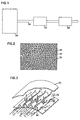
- FIG. 1 illustrates an exhaust system 20 that is in accordance with the inventive aspects of the present disclosure.
- the system includes an engine 22 (e.g., a diesel engine) and an exhaust conduit 24 for conveying exhaust gas away from the engine 22.
- a first diesel particulate reduction device 26 is positioned in the exhaust stream. Downstream from the first diesel particulate reduction device 26 is a second diesel particulate reduction device 28.
- the first diesel particulate reduction device 26 and the second diesel particulate reduction device 28 function together to treat the exhaust gas that passes through the conduit 24.
- the first diesel particulate reduction device 26 and the second diesel particulate reduction device 28 may be separated by any distance, including being positioned in close proximity or even in direct contact.
- the first diesel particulate reduction device 26, also referred to as the upstream diesel particulate reduction device 26, is preferably constructed from multiple layers of metallic fabric fleece material 30 sandwiched between layers of corrugated metallic foil 32. A cross section of this construction is shown in Figure 2 and a close-up exploded view is shown in Figure 3 .
- the corrugated metallic foil 32 defines elongated passageways 34 that are generally parallel to the net flow path of exhaust gases through the particulate reduction device. In operation, the exhaust gases enter through the exposed open ends of the passageways defined by the metallic foil.
- the metallic foil preferably contains mixing shovels 36 which direct the flow of the exhaust gases out of the passageways and into the fabric fleece material 30.
- the metallic fabric fleece material 30 is a woven-type material constructed from metallic fibers which capture particles both by impingement and by blocking their flow.
- the particle-blocking properties of the metallic fleece material 30 are determined in part by the diameter of the metallic fibers used to construct the fleece. For example, metallic fibers of 20 to 28 microns (millionths of a meter) and 35 to 45 microns have been found to work acceptably.
- the filtration material is manufactured by Emitec and referred to as "PM Kat.”
- the filtration material may, however, comprise any flow-through-type construction known to those of skill in the art, such as wire mesh, metallic or ceramic foam.
- the upstream diesel particulate reduction device 26 also contains a catalyst coating.
- catalyst coatings include precious metals such as platinum, palladium and rhodium, and other types of components such as base metals or zeolites.
- a preferred catalyst for the first particulate reduction device 26 is platinum with a loading level greater than 1050 (30) grams/m 3 (cubic foot) of substrate. In other embodiments the precious metal loading level is in the range of 1050-3500 (30-100) grams/m 3 (cubic foot) of substrate. The greater the loading level of the catalyst, the greater is the potential for oxidizing gases such as NO to NO 2 and for oxidizing the SOF particulates.
- the second diesel particulate reduction device 28, also called the downstream diesel particulate reduction device 28, may comprise the same construction as the upstream diesel particulate reduction device 26, preferably having multiple layers of metallic fabric fleece material sandwiched between layers of corrugated metallic foil.
- the downstream diesel particulate reduction device 28 may, however, comprise any flow-through-type construction, such as wire mesh or metallic or ceramic foam.
- the downstream diesel particulate reduction device 28 is either coated with a base metal catalyst without precious metal or is coated with a catalyst with a precious metal loading between 0.035 (0.001) grams/m 3 (cubic foot) and 525 (15) grams/m 3 (cubic foot), preferably 0.035 to 350 (0.001 to 10) grams/m 3 (cubic foot).
- the downstream diesel particulate reduction device 28 is generally constructed with different particle capture characteristics from those of the upstream device.
- the downstream diesel particulate reduction device 28 may be constructed from smaller diameter metallic fibers to increase the particulate capture efficiency.
- the system design parameters will depend in part on the NO x /particulate ratio and the exhaust mass flow rate of the engine. As discussed above, the NO x /particulate ratio depends largely on the emissions regulations in place at the time the engine is manufactured and the mass flow rate is related to the displacement and power output of the engine.
- the required precious metal loading will depend in part on the residence time of NO within the particulate reduction device, which in turn depends on the mass flow rate of exhaust gas and the volume of the particulate reduction device.
- the NO residence time may be expressed as a space velocity, defined as the volumetric flow rate of exhaust gases divided by the volume of the device per unit of time.
- the ratio of the mass of NO 2 to the mass of particulate matter in the exhaust stream should be between 3.5 and 16. More preferably, this ratio should be between 4.0 and 10. That is, the catalyst coating of the upstream diesel particulate reduction device is selected, based on the space velocity of the device, so that the sum of the NO 2 entering the upstream diesel particulate reduction device and the NO 2 generated within the upstream diesel particulate device is within the desired ratio. A certain amount of this NO 2 will be consumed in the upstream diesel particulate reduction device in reaction with the trapped particulate mass. However, a remaining portion of NO 2 will exit the upstream diesel particulate reduction device and enter the downstream diesel particulate reduction device.
- the amount of NO 2 in this remaining portion of NO 2 will depend on the amount of NO 2 generated in the upstream diesel particulate reduction device and the mass of particulate matter trapped in the upstream diesel particulate reduction device. If this remaining portion of NO 2 is insufficient to regenerate the downstream diesel particulate reduction device, then the downstream diesel particulate device should include a precious metal catalyst coating.
- the precious metal loading of this catalyst coating is selected, based on the space velocity of the device, so that the combination of the NO 2 that enters the downstream diesel particulate reduction device and the NO 2 that is generated within the downstream particulate reduction device are together sufficient to fully regenerate the downstream diesel particulate reduction device without excessively increasing the NO 2 emissions.
- the volumetric weighted particle capture efficiency of each particulate reduction device must also be selected.
- the volumetric weighted particle capture efficiency is computed by, first, subtracting the mass of particulate matter that exits the particulate reduction device from the mass of particulate that enters the particulate reduction device and dividing by the mass of particulate that enters the particulate reduction device; second, multiplying this number by the fraction of the particulate that constitutes hard carbon; and third, dividing by the volume of the particulate reduction device. For example, if a particulate reduction device has a hard carbon filtration efficiency of 20 percent and a volume of 4 dm 3 (liters), then the volumetric weighted particle capture efficiency will be 5.0.
- volumetric weighted particle capture efficiency will also be 5.0.
- the volume-weighted efficiency for the upstream diesel particulate reduction device will be equal to or less than the volume weighted efficiency of the downstream particulate reduction device.
- the volume-weighted efficiency of either particulate reduction device will be between 3 and 12.5.
- the parameters that are adjusted to create the desired volumetric weighted particle capture efficiency of each particulate reduction device are the cross sectional flow area, the flow length, the fabric wire size, and volume. A longer length or a smaller fabric wire size increases particle capture efficiency per unit of volume. For a given particle capture efficiency, decreasing the volume of the particulate reduction device increases the volumetric weighted particle capture efficiency. However, because of the nature of the physical construction of the particulate reduction device, the particle capture efficiency will generally not exceed 50 percent for one device.
- each particulate reduction device is also typically constrained by the amount of space available on the vehicle.
- the exhaust treatment system will fit within the same space on a vehicle as occupied by a conventional muffler.
- a conventional vertical muffler is about 25,4 cm (10 inches) in diameter and about 114,3 cm (45 inches) long and a conventional horizontal muffler is about 27,94 cm (11 inches) in diameter and about 91,44 to 106,68 cm (36 to 42 inches) long.
- one preferred configuration would be for the upstream diesel particulate reduction device to be 26,67 cm (10.5 inches) in diameter and 15,24 cm (6 inches) long and made from 40 micron metallic fibers and for the downstream diesel particulate reduction device to be 26,67 cm (10.5 inches) in diameter, 7,62 cm (3 inches) in length and made from 25 micron metallic fibers.
- This configuration would give a space velocity of the upstream diesel particulate reduction device of no higher than about 450,000 per hour (volumetric flow of exhaust gas divided by volume of the device).
- the catalyst coating of the upstream diesel particulate reduction device would be about 1750 (50) g/m 3 (ft 3 ) precious metal loading in order to generate sufficient NO 2 and yield a NO 2 /particulate matter ratio of greater than 4.
- the 40 micron fiber diameter and the longer length of the upstream diesel particulate reduction device are chosen to achieve a hard carbon capture efficiency of about 36 percent and a volumetric weighted efficiency of about 4.5.
- the 25 micron metallic fiber diameter and the shorter length of the downstream diesel particulate reduction device are chosen to achieve a hard carbon capture efficiency of about 28 percent and a volumetric weighted efficiency of about 7. These system parameters would generally be valid for engines with displacements between about 6 dm 3 (liters) and about 13 dm 3 (liters), with rated power levels between about 175 horsepower and 375 horsepower.
- the upstream diesel particulate reduction device As a second example, to apply this system to an on-highway diesel engine with a displacement of 7.3 liters certified under the emissions regulations in place between 1991 and 2002, where the NO x /particulate ratio under the applicable regulations was between 20 and 50 (as discussed above), one preferred configuration would be for the upstream diesel particulate reduction device to be 3 inches long, 10 1/2 inches in diameter, and made from 40 micron metallic fibers and for the downstream diesel particulate reduction device to be 26,67 cm (101/2 inches) in diameter, 15,24 cm (6 inches) in length, and made from 25 micron metallic fibers.
- the maximum space velocity of the upstream diesel particulate reduction device is no higher than 900,000 per hour, and preferably is between 20,000 and 800,000 per hour.
- the catalyst coating of the upstream diesel particulate reduction device would be about 2450 (70) g/m 3 (ft 3 ) precious metal loading in order to generate sufficient NO 2 and yield a NO 2 /particulate matter ratio of greater than 4.
- the 40 micron metallic fiber diameter for the upstream filter gives a hard carbon capture efficiency of about 20 percent, yielding a volumetric weighted efficiency of about 5.
- the 25 micron metallic fiber diameter for the downstream filter gives a hard carbon capture efficiency of about 48 percent, yielding a volumetric weighted efficiency of about 6.
- a first portion of the particulate matter contained in the diesel exhaust is deposited on the first diesel particulate reduction device 26 in an amount that is a function of the particle capture efficiency of the first diesel particulate reduction device 26.
- the exhaust gas exits the first diesel particulate reduction device 26 containing a residual portion of particulate matter, defined as the amount of particulate matter not deposited on the first diesel particulate reduction device 26.
- the exhaust gas thereafter enters the second diesel particulate reduction device 28, where a portion of the particulate matter present in the exhaust gas is deposited on the second diesel particulate reduction device 28 according to the particle capture efficiency of the second diesel particulate reduction device 28.
- the SOF portion of particulate matter is oxidized by contact with the oxidation catalyst coating. Furthermore, the NO present within the exhaust stream is converted to NO 2 by the oxidation catalyst coating within the first diesel particulate reduction device 26. A portion of this NO 2 , along with the NO 2 inherently present in the exhaust gas, reacts with the particulate matter trapped on the first diesel particulate reduction device 26.
- the exhaust gas exiting the first diesel particulate reduction device 26 contains a residual portion of NO 2 .
- This exhaust gas then enters the second diesel particulate reduction device 28.
- the second diesel particulate reduction device 28 is either not catalyzed or is lightly catalyzed, little or no additional NO 2 is formed in the second device.
- the NO 2 in the exhaust stream reacts with this soot, converting a portion of the NO 2 into NO. In this way, particulate matter is captured and the particulate reduction devices are regenerated while minimizing NO 2 emissions.
- the preferred design of the particulate reduction devices create significant internal, three-dimensional, turbulent flow patterns by virtue of the highly tortuous, twisted flow vectors that result from flow impacting into the fabric fleece material 30 and being channeled into and out of the openings in the corrugated foil 32.
- Other flow through filter designs such as wire mesh or ceramic or metallic foams produce similar favorable internal turbulence.
- This internal local turbulence increases the interaction of the exhaust gas with the catalytic coating on the filtration substrate material, thereby promoting the conversion of NO to NO 2 .
- this turbulence increases the interaction of the NO 2 with the particulate matter trapped on the surfaces of the diesel particulate reduction device. In doing so, the design of the diesel particulate reduction device promotes the consumption of NO 2 and the regeneration of the particulate filter.
- the particulate capture efficiency of each individual particulate reduction device is no greater than about 50 percent, by arranging the devices according to this disclosure the net particulate capture efficiency may be greater than 50 percent and can approach 85 percent.
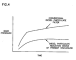
- the back pressure is substantially lower. The backpressure is lower both when the device is not loaded with particulate, such as immediately after being regenerated, and when the device is fully loaded with particulate. See Figure 4 .
- the back pressure of the diesel particulate matter reduction system according to the present disclosure is no greater than 4.5 inches of mercury.
- the increase in NO 2 emissions are minimized.
- the exhaust treatment system of the present disclosure increases the NO 2 /NO x ratio by no more than 20 percent over the engine output NO 2 /NO x ratio for engines that generate 0.33 (0.25) grams per kW (brake horsepower hour) or less of particulate matter.
Landscapes
- Engineering & Computer Science (AREA)
- Chemical & Material Sciences (AREA)
- Combustion & Propulsion (AREA)
- Mechanical Engineering (AREA)
- General Engineering & Computer Science (AREA)
- Chemical Kinetics & Catalysis (AREA)
- Health & Medical Sciences (AREA)
- Biomedical Technology (AREA)
- Environmental & Geological Engineering (AREA)
- Analytical Chemistry (AREA)
- General Chemical & Material Sciences (AREA)
- Oil, Petroleum & Natural Gas (AREA)
- Exhaust Gas After Treatment (AREA)
- Processes For Solid Components From Exhaust (AREA)
- Medicinal Preparation (AREA)
Claims (12)
- Dieselabgasbehandlungsystem (20), aufweisend:ein erstes Dieselpartikelreduziergerät (26);ein zweites Dieselpartikelreduziergerät (28), wobei eine volumetrisch gewichtete Partikelauffangeffizienz des ersten Dieselpartikelreduziergeräts (26) und eine volumetrisch gewichtete Partikelauffangeffizienz des zweiten Dieselpartikelreduziergeräts (28) jeweils in dem Bereich von 3 bis 12,5 liegt:wobei das erste Dieselpartikelreduziergerät (26) innerhalb des Abgasbehandlungsystems stromaufwärts von dem zweiten Dieselpartikelreduzisrgerät (28) positioniert ist;undwobei sowohl das erste als auch das zweite Dieselpartikelreduziergerät (26, 28) jeweils ein Filtersubstrat mit zwischen Schichten von gerillter Metallfolie (32) eingefügtem metallischem Fasermaterial (30) aufweisen, wobei die gerillte Metallfolie (32) längliche Durchtrittswege (34) definiert, die im Wesentlichen parallel zu einem Nettoflussweg von Abgas sind, wobei die gerillte Metallfolie Mischschaufeln (36) aufweist, die ein Abgasfluss aus den länglichen Durchtrittswegen (34) und in das metallische Fasermaterial lenken, wobei das metallische Fasermaterial (30) aus metallischen Fasern konstruiert ist,wobei das erste Dieselpartikelreduziergerät (26) eine erste Beladung mit Edelmetall aufweist, und das zweite Dieselpartikelreduziergerät (28) entweder i) eine zweite Beladung mit Edelmetall aufweist, die niedriger ist als die erste Beladung mit Edelmetall, oder ii) keine Beladung mit Edelmetall aufweist.
- Dieselabgasbehandlungsystem (20) nach Anspruch 1, wobei das zweite Dieselpartikelreduziergerät (28) eine größere volumetrisch gewichtete Partikelauffangeffienz aufweist, als das erste Dieselpartikelreduziergerät.
- Dieselabgasbehandlungssystem (20) nach Anspruch 1, wobei das zweite Dieselpartikelreduziergerät (28) metallische Fasern mit kleineren Durchmessern aufweist als die Durchmesser der metallischen Fasern des ersten Dieselpartikelreduziergerätes.
- Dieselabgasbehandlungssystem (20) nach Anspruch 1, wobei das zweite Dieselpartikelreduziergerät (28) eine höhere Partikelauffangeffizienz aufweist als das erste Dieselpartikelreduziergerät.
- Dieselabgasbehandlungssystem (20) nach Anspruch 1, wobei die Partikelauffangeffizienz für ein Gerät 50 % nicht übersteigt.
- Dieselabgasbehandlungssystem (20) nach Anspruch 1, wobei das zweite Dieselpartikelreduziergerät (28) ein größeres Volumen aufweist, als das erste Dieselpartikelreduziergerät.
- Dieselabgasbehandlungssystem (20) nach Anspruch 2, wobei das zweite Dieselpartikelreduziergerät (28) einen kleineren Durchmesser der metallischen Fasern aufweist als das erste Dieselpartikelreduziergerät.
- Dieselabgasbehandlungssystem (20) nach Anspruch 1, wobei das Abgasbehandlungssystem Emissionen von partikelartigem Material um mehr als 50 % reduziert und das Verhältnis NO2/NOx des Abgases nicht um mehr als 20 % gegenüber dem NO2/NOx-Verhältnis des von dem Motor (22) emittierten Abgases erhöht.
- Dieselabgasbehandlungssystem (20) nach Anspruch 1, wobei das erste Dieselpartikelreduziergerät (26) eine Katalysatorbeschichtung mit einer Edelmetallbeladung von 1050-3500 (30 bis 100) Gramm/m3 (pro Kubikfuß) von Substratmaterial aufweist.
- Dieselabgasbehandlungssystem (20) nach Anspruch 8, wobei der Abgasgegendruck nicht größer als 11,43 cm (4,5 Zoll) Quecksilber ist.
- Dieselabgasbehandlungssystem (20) nach Anspruch 1, wobei das erste Dieselpartikelreduziergerät (26) einen Durchmesser von etwa 7,62 cm (3 Zoll) und eine Länge von etwa 26,67 cm (10 ½ Zoll) aufweist, und wobei das zweite Dieselpartikelreduziergerät (28) einen Durchmesser von etwa 26,67 cm (10 ½ Zoll) und eine Länge von etwa 15.24 cm (6 Zoll) aufweist.
- Dieselabgasbehandlungssystem (20) nach Anspruch 1,
wobei mindestens das erste Dieselpartikelreduziergerät (26) eine erste Beladung mit Edelmetall aufweist, und wobei das Abgasbehandlungssystem das Verhältnis NO2/NOx um nicht mehr als 20 % über das NO2/NOx Verhältnis des Ausgangs des Motors (22) für Motoren (22) erhöht, die 0,33 (0,25) Gramm/kW (Brems-Pferdestärken) oder weniger von Partikelmaterial erzeugen.
Applications Claiming Priority (3)
| Application Number | Priority Date | Filing Date | Title |
|---|---|---|---|
| US67488205P | 2005-04-26 | 2005-04-26 | |
| US11/373,497 US7340888B2 (en) | 2005-04-26 | 2006-03-10 | Diesel particulate matter reduction system |
| PCT/US2006/010161 WO2006115629A1 (en) | 2005-04-26 | 2006-03-20 | Diesel particulate matter reduction system |
Publications (2)
| Publication Number | Publication Date |
|---|---|
| EP1877652A1 EP1877652A1 (de) | 2008-01-16 |
| EP1877652B1 true EP1877652B1 (de) | 2010-11-17 |
Family
ID=37185412
Family Applications (1)
| Application Number | Title | Priority Date | Filing Date |
|---|---|---|---|
| EP06739091A Expired - Lifetime EP1877652B1 (de) | 2005-04-26 | 2006-03-20 | System zur reduzierung von dieselpartikeln |
Country Status (5)
| Country | Link |
|---|---|
| US (1) | US7340888B2 (de) |
| EP (1) | EP1877652B1 (de) |
| AT (1) | ATE488675T1 (de) |
| DE (1) | DE602006018279D1 (de) |
| WO (1) | WO2006115629A1 (de) |
Families Citing this family (14)
| Publication number | Priority date | Publication date | Assignee | Title |
|---|---|---|---|---|
| DE102005049655A1 (de) * | 2005-10-18 | 2007-04-19 | Man Nutzfahrzeuge Ag | Verfahren zur Vermeidung von unerwünschten NO2-Emissionen bei Brennkraftmaschinen |
| US7862640B2 (en) * | 2006-03-21 | 2011-01-04 | Donaldson Company, Inc. | Low temperature diesel particulate matter reduction system |
| US20080120968A1 (en) | 2006-11-29 | 2008-05-29 | Douglas Munroe Beall | Partial wall-flow filter and diesel exhaust system and method |
| US8057746B2 (en) * | 2007-05-02 | 2011-11-15 | Acr Co., Ltd. | Carrier for exhaust-gas purification and exhaust-gas purifier having the carrier |
| JP2011522694A (ja) | 2008-05-29 | 2011-08-04 | コーニング インコーポレイテッド | 部分的壁流通式フィルタおよび方法 |
| DE102008035562A1 (de) * | 2008-07-30 | 2010-02-04 | Emitec Gesellschaft Für Emissionstechnologie Mbh | Abgasreinigungssystem für Dieselmotoren von Nutzkraftfahrzeugen |
| EP2358982B1 (de) | 2008-12-17 | 2017-11-08 | Donaldson Company, Inc. | Flussvorrichtung für ein abgassystem |
| KR101706398B1 (ko) * | 2009-04-22 | 2017-02-27 | 바스프 코포레이션 | Scr 촉매를 함유하는 부분 필터 기재 및 배출물 처리 시스템 및 엔진 배기가스의 처리 방법 |
| US8783022B2 (en) * | 2009-08-17 | 2014-07-22 | Donaldson Company, Inc. | Retrofit aftertreatment system for treating diesel exhaust |
| CN102686304B (zh) * | 2009-11-30 | 2016-01-13 | 康宁股份有限公司 | 具有槽形胞间孔的蜂窝状本体装置 |
| US8938954B2 (en) | 2012-04-19 | 2015-01-27 | Donaldson Company, Inc. | Integrated exhaust treatment device having compact configuration |
| US9863298B2 (en) | 2014-11-03 | 2018-01-09 | Caterpillar Inc. | Compression ignition engine system with improved regeneration via controlled ash deposits |
| US9694321B2 (en) | 2015-09-01 | 2017-07-04 | Caterpillar Inc. | Exhaust treatment system with particulate filter having wall-flow and flow-through channels |
| GB201704526D0 (en) | 2017-02-21 | 2017-05-03 | Porvair Filtration Group Ltd | Spacer and filtration apparatus containing it |
Family Cites Families (98)
| Publication number | Priority date | Publication date | Assignee | Title |
|---|---|---|---|---|
| BE623896A (de) | 1961-10-23 | |||
| US3318128A (en) | 1964-04-15 | 1967-05-09 | Ford Motor Co | Plaiting |
| GB1301667A (de) | 1969-05-09 | 1973-01-04 | ||
| DE10020170C1 (de) | 2000-04-25 | 2001-09-06 | Emitec Emissionstechnologie | Verfahren zum Entfernen von Rußpartikeln aus einem Abgas und zugehöriges Auffangelement |
| US3712030A (en) | 1970-09-14 | 1973-01-23 | J Priest | Exhaust depurator |
| GB1531134A (en) | 1975-08-20 | 1978-11-01 | Atomic Energy Authority Uk | Methods of fabricating bodies and to bodies so fabricated |
| GB1557780A (en) | 1976-09-29 | 1979-12-12 | Covrad Ltd | Method and apparatus for forming louvred corrugations in strip or sheet metal |
| US4319896A (en) | 1979-03-15 | 1982-03-16 | Texaco Inc. | Smoke filter rejuvenation system |
| US4535588A (en) | 1979-06-12 | 1985-08-20 | Nippon Soken, Inc. | Carbon particulates cleaning device for diesel engine |
| SE437542B (sv) | 1979-10-01 | 1985-03-04 | Tom Ove Artur Rehnberg | Forfarande for att optimera rening av dieselavgaser |
| US4276071A (en) | 1979-12-03 | 1981-06-30 | General Motors Corporation | Ceramic filters for diesel exhaust particulates |
| DE2951316A1 (de) | 1979-12-20 | 1981-07-02 | Degussa Ag, 6000 Frankfurt | Katalytisches filter fuer die dieselabgasreinigung |
| US4372111A (en) | 1980-03-03 | 1983-02-08 | Texaco Inc. | Method for cyclic rejuvenation of an exhaust gas filter and apparatus |
| US4416674A (en) | 1980-10-27 | 1983-11-22 | Texaco Inc. | Filter for treating a particle-carrying gaseous stream |
| US4404007A (en) | 1980-12-11 | 1983-09-13 | Nippon Soken, Inc. | Exhaust gas cleaning element |
| JPS57117326A (en) * | 1981-01-12 | 1982-07-21 | Toyota Motor Corp | Filter for exhaust gas of internal-combustion engine |
| US4451441A (en) | 1981-01-27 | 1984-05-29 | W. R. Grace & Co. | Method for exhaust gas treatment |
| US4464185A (en) | 1981-03-07 | 1984-08-07 | Nippon Soken, Inc. | Exhaust gas filter |
| AU540009B2 (en) | 1982-02-16 | 1984-10-25 | Matsushita Electric Industrial Co., Ltd. | Exhaust gas filter |
| US4419108A (en) | 1982-02-22 | 1983-12-06 | Corning Glass Works | Filter apparatus and method of filtering |
| US4462812A (en) | 1982-12-08 | 1984-07-31 | General Motors Corporation | Ceramic monolith particulate trap including filter support |
| JPS59150918A (ja) * | 1983-02-16 | 1984-08-29 | Hitachi Ltd | デイ−ゼルエンジンの排気ガス浄化装置 |
| US4478618A (en) | 1983-08-01 | 1984-10-23 | General Motors Corporation | Diesel exhaust particulate trap with plural filter tubes |
| DE3337903A1 (de) | 1983-10-19 | 1985-05-09 | Werner 7101 Flein Baum | Katalysatoranordnung |
| ATE39853T1 (de) | 1984-04-23 | 1989-01-15 | Engelhard Corp | Katalytischer abgasfilter fuer teilchen eines dieselmotors. |
| USRE33118E (en) | 1984-08-13 | 1989-11-28 | Arvin Industries, Inc. | Exhaust processor |
| US4625511A (en) | 1984-08-13 | 1986-12-02 | Arvin Industries, Inc. | Exhaust processor |
| CH665002A5 (de) | 1984-11-09 | 1988-04-15 | Bbc Brown Boveri & Cie | Verfahren und einrichtung zum betrieb eines dieselmotors mit einer abgasfiltriereinrichtung. |
| US4665690A (en) | 1985-01-14 | 1987-05-19 | Mazda Motor Corporation | Exhaust gas cleaning system for vehicle |
| GB8516420D0 (en) | 1985-06-28 | 1985-07-31 | Ontario Research Foundation | Diesel particulate traps |
| DE3545762A1 (de) | 1985-12-21 | 1987-07-02 | Leistritz Maschfabrik Paul | Russfilter |
| CA1285493C (en) | 1986-01-06 | 1991-07-02 | Robert Hoch | Method and apparatus for filtering solid particulate matter from diesel engine exhaust |
| DE3608635A1 (de) | 1986-03-14 | 1987-09-17 | Drache Keramikfilter | Abgasreaktor und verfahren zu seiner herstellung |
| JPS648311U (de) | 1987-07-07 | 1989-01-18 | ||
| JPH01159029A (ja) * | 1987-12-16 | 1989-06-22 | Toyota Motor Corp | ディーゼルエンジンの排気浄化装置 |
| DE3744265C2 (de) | 1987-12-24 | 1996-07-11 | Emitec Emissionstechnologie | Rußfilter zur Abgasreinigung in Kraftfahrzeugen |
| US4916897A (en) | 1988-01-08 | 1990-04-17 | Toyota Jidosha Kabushiki Kaisha | Exhaust gas purifying apparatus built-in to a muffler for a diesel engine |
| US4814081A (en) | 1988-01-19 | 1989-03-21 | Malinowski Raymond J | Honeycombed filter support disc |
| DE3805395A1 (de) | 1988-02-20 | 1989-08-31 | Man Technologie Gmbh | Elektrostatischer dieselpartikelfilter |
| US4902487A (en) | 1988-05-13 | 1990-02-20 | Johnson Matthey, Inc. | Treatment of diesel exhaust gases |
| US4961314A (en) | 1988-08-15 | 1990-10-09 | Arvin Industries, Inc. | Tuned exhaust processor assembly |
| EP0369163A1 (de) | 1988-10-11 | 1990-05-23 | Sakai Chemical Industry Co., Ltd., | Katalytisches Filter und Verfahren zur Entfernung von Teilchen |
| JPH02196120A (ja) * | 1989-01-24 | 1990-08-02 | Nissan Motor Co Ltd | 内燃機関の排気微粒子処理装置 |
| EP0393257A1 (de) | 1989-04-17 | 1990-10-24 | Emitec Gesellschaft für Emissionstechnologie mbH | Dieselrussfilter mit zusätzlicher Einrichtung zur Reduktion von Stickoxyden und/oder Oxydation von Kohlenmonoxyd |
| EP0468955A1 (de) | 1989-04-17 | 1992-02-05 | Emitec Gesellschaft für Emissionstechnologie mbH | Dieselrussfilter mit zusätzlicher einrichtung zur reduktion von stickoxyden und/oder oxydation von kohlenmonoxyd |
| US5243819A (en) | 1989-12-12 | 1993-09-14 | J. Eberspacher | Exhaust gas cleaning device for diesel engines |
| BR9007939A (pt) | 1989-12-22 | 1992-10-06 | Emitec Emissionstechnologie | Cano de descarga com corpo de sustentacao catalisador afluido helicoidalmente |
| DE4002754C2 (de) | 1990-01-31 | 1994-03-17 | Daimler Benz Ag | Im Zuluftstrom einer Heiz- oder Klimaanlage eines Kraftwagens eingesetzte Filteranordnung |
| US5065574A (en) | 1990-05-29 | 1991-11-19 | Caterpillar Inc. | Particulate trap regeneration apparatus and method |
| DE4021495A1 (de) | 1990-07-05 | 1992-01-09 | Schwaebische Huettenwerke Gmbh | Abgasfilter |
| US5082479A (en) | 1990-07-16 | 1992-01-21 | Cummins Engine Company, Inc. | Diesel particulate trap mounting system |
| US5212948A (en) | 1990-09-27 | 1993-05-25 | Donaldson Company, Inc. | Trap apparatus with bypass |
| US5248482A (en) | 1991-04-05 | 1993-09-28 | Minnesota Mining And Manufacturing Company | Diesel particulate trap of perforated tubes wrapped with cross-wound inorganic yarn to form four-sided filter traps |
| AU2246092A (en) | 1991-06-27 | 1993-01-25 | Donaldson Company Inc. | Trap apparatus with tubular filter element |
| JPH05306614A (ja) | 1992-04-28 | 1993-11-19 | Matsushita Electric Ind Co Ltd | 排気ガスフィルタとその製造方法 |
| JP2894103B2 (ja) | 1992-09-09 | 1999-05-24 | 松下電器産業株式会社 | 排気ガス浄化装置 |
| JPH06294316A (ja) * | 1993-04-09 | 1994-10-21 | Isuzu Ceramics Kenkyusho:Kk | ディーゼルパティキュレートフィルタ |
| US5396764A (en) | 1994-02-14 | 1995-03-14 | Ford Motor Company | Spark ignition engine exhaust system |
| US5787707A (en) | 1994-08-02 | 1998-08-04 | Corning Incorporated | In-line adsorber system |
| EP0697505A1 (de) | 1994-08-02 | 1996-02-21 | Corning Incorporated | Adsorptionsvorrichtung in Reihe |
| JP3899534B2 (ja) | 1995-08-14 | 2007-03-28 | トヨタ自動車株式会社 | ディーゼル機関の排気浄化方法 |
| JP3434117B2 (ja) | 1996-03-29 | 2003-08-04 | 住友電気工業株式会社 | ディーゼルエンジン用パティキュレートトラップ |
| GB9621215D0 (en) | 1996-10-11 | 1996-11-27 | Johnson Matthey Plc | Emission control |
| DE19704147A1 (de) | 1997-02-04 | 1998-08-06 | Emitec Emissionstechnologie | Hitzebeständiger und regenerierbarer Filterkörper mit Strömungswegen |
| US5771868A (en) | 1997-07-03 | 1998-06-30 | Turbodyne Systems, Inc. | Turbocharging systems for internal combustion engines |
| DE19755354A1 (de) | 1997-12-12 | 1999-06-17 | Emitec Emissionstechnologie | Metallfolie mit Durchbrechungen |
| GB9802504D0 (en) | 1998-02-06 | 1998-04-01 | Johnson Matthey Plc | Improvements in emission control |
| GB9804739D0 (en) | 1998-03-06 | 1998-04-29 | Johnson Matthey Plc | Improvements in emissions control |
| US6325834B1 (en) | 1998-05-18 | 2001-12-04 | Roberto Fonseca | Exhaust filter and catalyst structure |
| DE19923781C2 (de) | 1999-05-22 | 2001-04-26 | Degussa | Verfahren und Vorrichtung zur Entfernung von Ruß aus dem Abgas eines Dieselmotors |
| ES2284503T3 (es) | 1999-07-02 | 2007-11-16 | Basf Catalysts Llc | Sistema catalizador para tratar gases de escape de motores diesel y procedimiento. |
| JP2001115822A (ja) | 1999-10-19 | 2001-04-24 | Hino Motors Ltd | ディーゼルエンジンのパティキュレートフィルタ再生装置 |
| US6669913B1 (en) | 2000-03-09 | 2003-12-30 | Fleetguard, Inc. | Combination catalytic converter and filter |
| US6582490B2 (en) | 2000-05-18 | 2003-06-24 | Fleetguard, Inc. | Pre-form for exhaust aftertreatment control filter |
| US6776814B2 (en) | 2000-03-09 | 2004-08-17 | Fleetguard, Inc. | Dual section exhaust aftertreatment filter and method |
| JP3566905B2 (ja) * | 2000-04-17 | 2004-09-15 | 日野自動車株式会社 | 排気浄化装置 |
| DE10026696A1 (de) | 2000-05-30 | 2001-12-20 | Emitec Emissionstechnologie | Partikelfalle |
| JP2001355431A (ja) * | 2000-06-16 | 2001-12-26 | Isuzu Motors Ltd | ディーゼルエンジンの排気浄化装置 |
| DE10031200A1 (de) | 2000-06-27 | 2002-01-17 | Emitec Emissionstechnologie | Partikelfalle zum Abscheiden von Partikeln aus dem Strom eines Fluids, Verfahren zum Abscheiden von Partikeln aus dem Strom eines Fluids und Verwendung einer Partikelfalle |
| US6673136B2 (en) | 2000-09-05 | 2004-01-06 | Donaldson Company, Inc. | Air filtration arrangements having fluted media constructions and methods |
| JP4889873B2 (ja) | 2000-09-08 | 2012-03-07 | 日産自動車株式会社 | 排気ガス浄化システム、これに用いる排気ガス浄化触媒及び排気浄化方法 |
| JP2002213227A (ja) * | 2000-11-17 | 2002-07-31 | Toyota Motor Corp | 排気ガス浄化装置、および排気ガスの浄化方法 |
| JP3925154B2 (ja) | 2000-12-25 | 2007-06-06 | 株式会社デンソー | 排ガス浄化フィルタ |
| EP1251248A1 (de) | 2001-04-18 | 2002-10-23 | OMG AG & Co. KG | Verfahren und Vorrichtung zur Entfernung von Russpartikeln aus dem Abgas eines Dieselmotors |
| JP3840923B2 (ja) | 2001-06-20 | 2006-11-01 | いすゞ自動車株式会社 | ディーゼルエンジンの排気浄化装置 |
| DE20117659U1 (de) | 2001-10-29 | 2002-01-10 | Emitec Gesellschaft für Emissionstechnologie mbH, 53797 Lohmar | Offener Partikelfilter mit Heizelement |
| DE10153284A1 (de) * | 2001-10-29 | 2003-05-15 | Emitec Emissionstechnologie | Filterverbund und Verfahren zu seiner Herstellung |
| DE20117873U1 (de) | 2001-11-06 | 2002-02-14 | Emitec Gesellschaft für Emissionstechnologie mbH, 53797 Lohmar | Offener Filterkörper mit verbesserten Strömungseigenschaften |
| GB0218540D0 (en) | 2002-08-09 | 2002-09-18 | Johnson Matthey Plc | Engine exhaust treatment |
| JP4172986B2 (ja) | 2002-10-10 | 2008-10-29 | 日本碍子株式会社 | ハニカム構造体及びその製造方法並びに当該ハニカム構造体を用いた排ガス浄化システム |
| JP2004162613A (ja) | 2002-11-13 | 2004-06-10 | Mitsubishi Fuso Truck & Bus Corp | 内燃機関の排気浄化装置 |
| DE10254764A1 (de) | 2002-11-22 | 2004-06-03 | Emitec Gesellschaft Für Emissionstechnologie Mbh | Abgasanlage |
| DE10257113A1 (de) | 2002-12-05 | 2004-06-24 | Emitec Gesellschaft Für Emissionstechnologie Mbh | Partikelfalle mit beschichteter Faserlage |
| DE10304814C5 (de) | 2003-02-06 | 2009-07-02 | Emitec Gesellschaft Für Emissionstechnologie Mbh | Verfahren und Werkzeug zur Herstellung von strukturierten Blechlagen; Katalysator-Trägerkörper |
| JP3711117B2 (ja) * | 2003-03-25 | 2005-10-26 | 株式会社東芝 | 無線受信装置 |
| DE10321105A1 (de) | 2003-05-09 | 2004-12-02 | Emitec Gesellschaft Für Emissionstechnologie Mbh | Regeneration einer Partikelfalle |
| JP4333289B2 (ja) * | 2003-09-03 | 2009-09-16 | いすゞ自動車株式会社 | 排気ガス浄化システム |
| JP2005180262A (ja) | 2003-12-18 | 2005-07-07 | Tetsuo Toyoda | 粒子状物質の減少装置 |
-
2006
- 2006-03-10 US US11/373,497 patent/US7340888B2/en not_active Expired - Fee Related
- 2006-03-20 AT AT06739091T patent/ATE488675T1/de not_active IP Right Cessation
- 2006-03-20 WO PCT/US2006/010161 patent/WO2006115629A1/en not_active Ceased
- 2006-03-20 EP EP06739091A patent/EP1877652B1/de not_active Expired - Lifetime
- 2006-03-20 DE DE602006018279T patent/DE602006018279D1/de not_active Expired - Lifetime
Also Published As
| Publication number | Publication date |
|---|---|
| DE602006018279D1 (de) | 2010-12-30 |
| US20060236684A1 (en) | 2006-10-26 |
| ATE488675T1 (de) | 2010-12-15 |
| EP1877652A1 (de) | 2008-01-16 |
| WO2006115629A1 (en) | 2006-11-02 |
| US7340888B2 (en) | 2008-03-11 |
Similar Documents
| Publication | Publication Date | Title |
|---|---|---|
| EP2002094B1 (de) | Niedertemperatursystem zur reduktion von dieselpartikeln | |
| US7340888B2 (en) | Diesel particulate matter reduction system | |
| JP6436615B2 (ja) | Scr触媒を含むパーシャルフィルタ基板及び排出処理システム及びエンジンの排気処理方法 | |
| KR101028548B1 (ko) | 배기가스 정화장치 | |
| EP1446215B1 (de) | Dieselteilchenfilter mit kontinuierlicher regeneration | |
| CN101779013B (zh) | 排气净化装置 | |
| CN100371564C (zh) | 带有涂覆的纤维层的颗粒陷阱 | |
| JP4639024B2 (ja) | 排気ガスからすす粒子を除去する方法と関連する集塵要素 | |
| CN104295349A (zh) | 用于减少柴油发动机废气中的氮氧化物的方法以及用于实施所述方法的废气后处理系统 | |
| RU2007131191A (ru) | Система дополнительной обработки выхлопных газов | |
| WO1999044725A1 (en) | Improvements in emissions control | |
| JP2004084666A (ja) | ディーゼルエンジンの排気ガスからのスス微粒子の除去 | |
| US20020170433A1 (en) | Process and device for removing soot particles from diesel engine exhaust gas | |
| KR101174113B1 (ko) | 매연 저감 장치용 메탈 폼 필터 | |
| EP1251249B2 (de) | Verfahren und Vorrichtung zum Entfernen von Russpartikeln aus dem Abgas eines Dieselmotors | |
| US20050056977A1 (en) | Apparatus for removing carbon particles from an exhaust gas stream of internal combustion engines | |
| KR20110065985A (ko) | 입자상물질 및 질소산화물을 제거하기 위한 일체형 촉매정화장치 | |
| JP2007332849A (ja) | 排気浄化装置 | |
| CN117211939B (zh) | 一种老式特种车辆尾气后处理装置的设计方法 | |
| JP2002537965A (ja) | モノリス触媒/フィルタ装置 | |
| JP2006110459A (ja) | 排ガス用フィルタ | |
| CN204419316U (zh) | 一种轻型客车及其柴油机催化器 | |
| JP2005201155A (ja) | 排ガス浄化装置 | |
| JP2003320211A (ja) | 排ガス処理方法及び装置 | |
| KR20110012330A (ko) | 디젤엔진의 배기가스 후처리 시스템 |
Legal Events
| Date | Code | Title | Description |
|---|---|---|---|
| PUAI | Public reference made under article 153(3) epc to a published international application that has entered the european phase |
Free format text: ORIGINAL CODE: 0009012 |
|
| 17P | Request for examination filed |
Effective date: 20071126 |
|
| AK | Designated contracting states |
Kind code of ref document: A1 Designated state(s): AT BE BG CH CY CZ DE DK EE ES FI FR GB GR HU IE IS IT LI LT LU LV MC NL PL PT RO SE SI SK TR |
|
| 17Q | First examination report despatched |
Effective date: 20080402 |
|
| DAX | Request for extension of the european patent (deleted) | ||
| GRAP | Despatch of communication of intention to grant a patent |
Free format text: ORIGINAL CODE: EPIDOSNIGR1 |
|
| GRAS | Grant fee paid |
Free format text: ORIGINAL CODE: EPIDOSNIGR3 |
|
| GRAA | (expected) grant |
Free format text: ORIGINAL CODE: 0009210 |
|
| AK | Designated contracting states |
Kind code of ref document: B1 Designated state(s): AT BE BG CH CY CZ DE DK EE ES FI FR GB GR HU IE IS IT LI LT LU LV MC NL PL PT RO SE SI SK TR |
|
| REG | Reference to a national code |
Ref country code: GB Ref legal event code: FG4D |
|
| REG | Reference to a national code |
Ref country code: CH Ref legal event code: EP |
|
| REG | Reference to a national code |
Ref country code: IE Ref legal event code: FG4D |
|
| REF | Corresponds to: |
Ref document number: 602006018279 Country of ref document: DE Date of ref document: 20101230 Kind code of ref document: P |
|
| REG | Reference to a national code |
Ref country code: NL Ref legal event code: VDEP Effective date: 20101117 |
|
| LTIE | Lt: invalidation of european patent or patent extension |
Effective date: 20101117 |
|
| PG25 | Lapsed in a contracting state [announced via postgrant information from national office to epo] |
Ref country code: LT Free format text: LAPSE BECAUSE OF FAILURE TO SUBMIT A TRANSLATION OF THE DESCRIPTION OR TO PAY THE FEE WITHIN THE PRESCRIBED TIME-LIMIT Effective date: 20101117 |
|
| PG25 | Lapsed in a contracting state [announced via postgrant information from national office to epo] |
Ref country code: CY Free format text: LAPSE BECAUSE OF FAILURE TO SUBMIT A TRANSLATION OF THE DESCRIPTION OR TO PAY THE FEE WITHIN THE PRESCRIBED TIME-LIMIT Effective date: 20101117 Ref country code: LV Free format text: LAPSE BECAUSE OF FAILURE TO SUBMIT A TRANSLATION OF THE DESCRIPTION OR TO PAY THE FEE WITHIN THE PRESCRIBED TIME-LIMIT Effective date: 20101117 Ref country code: IS Free format text: LAPSE BECAUSE OF FAILURE TO SUBMIT A TRANSLATION OF THE DESCRIPTION OR TO PAY THE FEE WITHIN THE PRESCRIBED TIME-LIMIT Effective date: 20110317 Ref country code: PT Free format text: LAPSE BECAUSE OF FAILURE TO SUBMIT A TRANSLATION OF THE DESCRIPTION OR TO PAY THE FEE WITHIN THE PRESCRIBED TIME-LIMIT Effective date: 20110317 Ref country code: NL Free format text: LAPSE BECAUSE OF FAILURE TO SUBMIT A TRANSLATION OF THE DESCRIPTION OR TO PAY THE FEE WITHIN THE PRESCRIBED TIME-LIMIT Effective date: 20101117 Ref country code: BG Free format text: LAPSE BECAUSE OF FAILURE TO SUBMIT A TRANSLATION OF THE DESCRIPTION OR TO PAY THE FEE WITHIN THE PRESCRIBED TIME-LIMIT Effective date: 20110217 Ref country code: SI Free format text: LAPSE BECAUSE OF FAILURE TO SUBMIT A TRANSLATION OF THE DESCRIPTION OR TO PAY THE FEE WITHIN THE PRESCRIBED TIME-LIMIT Effective date: 20101117 Ref country code: AT Free format text: LAPSE BECAUSE OF FAILURE TO SUBMIT A TRANSLATION OF THE DESCRIPTION OR TO PAY THE FEE WITHIN THE PRESCRIBED TIME-LIMIT Effective date: 20101117 Ref country code: SE Free format text: LAPSE BECAUSE OF FAILURE TO SUBMIT A TRANSLATION OF THE DESCRIPTION OR TO PAY THE FEE WITHIN THE PRESCRIBED TIME-LIMIT Effective date: 20101117 |
|
| PG25 | Lapsed in a contracting state [announced via postgrant information from national office to epo] |
Ref country code: GR Free format text: LAPSE BECAUSE OF FAILURE TO SUBMIT A TRANSLATION OF THE DESCRIPTION OR TO PAY THE FEE WITHIN THE PRESCRIBED TIME-LIMIT Effective date: 20110218 |
|
| PG25 | Lapsed in a contracting state [announced via postgrant information from national office to epo] |
Ref country code: EE Free format text: LAPSE BECAUSE OF FAILURE TO SUBMIT A TRANSLATION OF THE DESCRIPTION OR TO PAY THE FEE WITHIN THE PRESCRIBED TIME-LIMIT Effective date: 20101117 Ref country code: CZ Free format text: LAPSE BECAUSE OF FAILURE TO SUBMIT A TRANSLATION OF THE DESCRIPTION OR TO PAY THE FEE WITHIN THE PRESCRIBED TIME-LIMIT Effective date: 20101117 Ref country code: BE Free format text: LAPSE BECAUSE OF FAILURE TO SUBMIT A TRANSLATION OF THE DESCRIPTION OR TO PAY THE FEE WITHIN THE PRESCRIBED TIME-LIMIT Effective date: 20101117 Ref country code: ES Free format text: LAPSE BECAUSE OF FAILURE TO SUBMIT A TRANSLATION OF THE DESCRIPTION OR TO PAY THE FEE WITHIN THE PRESCRIBED TIME-LIMIT Effective date: 20110228 |
|
| PG25 | Lapsed in a contracting state [announced via postgrant information from national office to epo] |
Ref country code: RO Free format text: LAPSE BECAUSE OF FAILURE TO SUBMIT A TRANSLATION OF THE DESCRIPTION OR TO PAY THE FEE WITHIN THE PRESCRIBED TIME-LIMIT Effective date: 20101117 Ref country code: SK Free format text: LAPSE BECAUSE OF FAILURE TO SUBMIT A TRANSLATION OF THE DESCRIPTION OR TO PAY THE FEE WITHIN THE PRESCRIBED TIME-LIMIT Effective date: 20101117 Ref country code: DK Free format text: LAPSE BECAUSE OF FAILURE TO SUBMIT A TRANSLATION OF THE DESCRIPTION OR TO PAY THE FEE WITHIN THE PRESCRIBED TIME-LIMIT Effective date: 20101117 Ref country code: PL Free format text: LAPSE BECAUSE OF FAILURE TO SUBMIT A TRANSLATION OF THE DESCRIPTION OR TO PAY THE FEE WITHIN THE PRESCRIBED TIME-LIMIT Effective date: 20101117 |
|
| PLBE | No opposition filed within time limit |
Free format text: ORIGINAL CODE: 0009261 |
|
| STAA | Information on the status of an ep patent application or granted ep patent |
Free format text: STATUS: NO OPPOSITION FILED WITHIN TIME LIMIT |
|
| 26N | No opposition filed |
Effective date: 20110818 |
|
| PG25 | Lapsed in a contracting state [announced via postgrant information from national office to epo] |
Ref country code: MC Free format text: LAPSE BECAUSE OF NON-PAYMENT OF DUE FEES Effective date: 20110331 |
|
| REG | Reference to a national code |
Ref country code: CH Ref legal event code: PL |
|
| GBPC | Gb: european patent ceased through non-payment of renewal fee |
Effective date: 20110320 |
|
| REG | Reference to a national code |
Ref country code: DE Ref legal event code: R097 Ref document number: 602006018279 Country of ref document: DE Effective date: 20110818 |
|
| PG25 | Lapsed in a contracting state [announced via postgrant information from national office to epo] |
Ref country code: IT Free format text: LAPSE BECAUSE OF FAILURE TO SUBMIT A TRANSLATION OF THE DESCRIPTION OR TO PAY THE FEE WITHIN THE PRESCRIBED TIME-LIMIT Effective date: 20101117 |
|
| REG | Reference to a national code |
Ref country code: IE Ref legal event code: MM4A |
|
| PG25 | Lapsed in a contracting state [announced via postgrant information from national office to epo] |
Ref country code: IE Free format text: LAPSE BECAUSE OF NON-PAYMENT OF DUE FEES Effective date: 20110320 Ref country code: CH Free format text: LAPSE BECAUSE OF NON-PAYMENT OF DUE FEES Effective date: 20110331 Ref country code: LI Free format text: LAPSE BECAUSE OF NON-PAYMENT OF DUE FEES Effective date: 20110331 |
|
| PG25 | Lapsed in a contracting state [announced via postgrant information from national office to epo] |
Ref country code: GB Free format text: LAPSE BECAUSE OF NON-PAYMENT OF DUE FEES Effective date: 20110320 |
|
| PG25 | Lapsed in a contracting state [announced via postgrant information from national office to epo] |
Ref country code: LU Free format text: LAPSE BECAUSE OF NON-PAYMENT OF DUE FEES Effective date: 20110320 |
|
| PG25 | Lapsed in a contracting state [announced via postgrant information from national office to epo] |
Ref country code: TR Free format text: LAPSE BECAUSE OF FAILURE TO SUBMIT A TRANSLATION OF THE DESCRIPTION OR TO PAY THE FEE WITHIN THE PRESCRIBED TIME-LIMIT Effective date: 20101117 |
|
| PG25 | Lapsed in a contracting state [announced via postgrant information from national office to epo] |
Ref country code: HU Free format text: LAPSE BECAUSE OF FAILURE TO SUBMIT A TRANSLATION OF THE DESCRIPTION OR TO PAY THE FEE WITHIN THE PRESCRIBED TIME-LIMIT Effective date: 20101117 |
|
| REG | Reference to a national code |
Ref country code: FR Ref legal event code: PLFP Year of fee payment: 10 |
|
| PGFP | Annual fee paid to national office [announced via postgrant information from national office to epo] |
Ref country code: DE Payment date: 20150327 Year of fee payment: 10 Ref country code: FI Payment date: 20150327 Year of fee payment: 10 |
|
| PGFP | Annual fee paid to national office [announced via postgrant information from national office to epo] |
Ref country code: FR Payment date: 20150317 Year of fee payment: 10 |
|
| REG | Reference to a national code |
Ref country code: DE Ref legal event code: R119 Ref document number: 602006018279 Country of ref document: DE |
|
| PG25 | Lapsed in a contracting state [announced via postgrant information from national office to epo] |
Ref country code: FI Free format text: LAPSE BECAUSE OF NON-PAYMENT OF DUE FEES Effective date: 20160320 |
|
| REG | Reference to a national code |
Ref country code: FR Ref legal event code: ST Effective date: 20161130 |
|
| PG25 | Lapsed in a contracting state [announced via postgrant information from national office to epo] |
Ref country code: DE Free format text: LAPSE BECAUSE OF NON-PAYMENT OF DUE FEES Effective date: 20161001 Ref country code: FR Free format text: LAPSE BECAUSE OF NON-PAYMENT OF DUE FEES Effective date: 20160331 |