EP1871003A1 - Motorantrieb und kompressorantrieb - Google Patents
Motorantrieb und kompressorantrieb Download PDFInfo
- Publication number
- EP1871003A1 EP1871003A1 EP06834464A EP06834464A EP1871003A1 EP 1871003 A1 EP1871003 A1 EP 1871003A1 EP 06834464 A EP06834464 A EP 06834464A EP 06834464 A EP06834464 A EP 06834464A EP 1871003 A1 EP1871003 A1 EP 1871003A1
- Authority
- EP
- European Patent Office
- Prior art keywords
- current
- electric motor
- direct
- voltage
- current voltage
- Prior art date
- Legal status (The legal status is an assumption and is not a legal conclusion. Google has not performed a legal analysis and makes no representation as to the accuracy of the status listed.)
- Ceased
Links
Images


Classifications
-
- F—MECHANICAL ENGINEERING; LIGHTING; HEATING; WEAPONS; BLASTING
- F24—HEATING; RANGES; VENTILATING
- F24F—AIR-CONDITIONING; AIR-HUMIDIFICATION; VENTILATION; USE OF AIR CURRENTS FOR SCREENING
- F24F11/00—Control or safety arrangements
- F24F11/70—Control systems characterised by their outputs; Constructional details thereof
- F24F11/80—Control systems characterised by their outputs; Constructional details thereof for controlling the temperature of the supplied air
- F24F11/83—Control systems characterised by their outputs; Constructional details thereof for controlling the temperature of the supplied air by controlling the supply of heat-exchange fluids to heat-exchangers
-
- F—MECHANICAL ENGINEERING; LIGHTING; HEATING; WEAPONS; BLASTING
- F24—HEATING; RANGES; VENTILATING
- F24F—AIR-CONDITIONING; AIR-HUMIDIFICATION; VENTILATION; USE OF AIR CURRENTS FOR SCREENING
- F24F11/00—Control or safety arrangements
- F24F11/88—Electrical aspects, e.g. circuits
-
- F—MECHANICAL ENGINEERING; LIGHTING; HEATING; WEAPONS; BLASTING
- F25—REFRIGERATION OR COOLING; COMBINED HEATING AND REFRIGERATION SYSTEMS; HEAT PUMP SYSTEMS; MANUFACTURE OR STORAGE OF ICE; LIQUEFACTION SOLIDIFICATION OF GASES
- F25B—REFRIGERATION MACHINES, PLANTS OR SYSTEMS; COMBINED HEATING AND REFRIGERATION SYSTEMS; HEAT PUMP SYSTEMS
- F25B2600/00—Control issues
- F25B2600/02—Compressor control
- F25B2600/021—Inverters therefor
-
- F—MECHANICAL ENGINEERING; LIGHTING; HEATING; WEAPONS; BLASTING
- F25—REFRIGERATION OR COOLING; COMBINED HEATING AND REFRIGERATION SYSTEMS; HEAT PUMP SYSTEMS; MANUFACTURE OR STORAGE OF ICE; LIQUEFACTION SOLIDIFICATION OF GASES
- F25B—REFRIGERATION MACHINES, PLANTS OR SYSTEMS; COMBINED HEATING AND REFRIGERATION SYSTEMS; HEAT PUMP SYSTEMS
- F25B2600/00—Control issues
- F25B2600/11—Fan speed control
-
- Y—GENERAL TAGGING OF NEW TECHNOLOGICAL DEVELOPMENTS; GENERAL TAGGING OF CROSS-SECTIONAL TECHNOLOGIES SPANNING OVER SEVERAL SECTIONS OF THE IPC; TECHNICAL SUBJECTS COVERED BY FORMER USPC CROSS-REFERENCE ART COLLECTIONS [XRACs] AND DIGESTS
- Y02—TECHNOLOGIES OR APPLICATIONS FOR MITIGATION OR ADAPTATION AGAINST CLIMATE CHANGE
- Y02B—CLIMATE CHANGE MITIGATION TECHNOLOGIES RELATED TO BUILDINGS, e.g. HOUSING, HOUSE APPLIANCES OR RELATED END-USER APPLICATIONS
- Y02B30/00—Energy efficient heating, ventilation or air conditioning [HVAC]
- Y02B30/70—Efficient control or regulation technologies, e.g. for control of refrigerant flow, motor or heating
Definitions
- the present invention relates to an electric motor driving device and a compressor driving device, and more particularly, relates to a method of reducing a capacity of a capacitor for smoothing a direct current voltage to be small.
- a device configured that "...a voltage command value is made, a PWM signal of a pulse width corresponding to the voltage command value is outputted, and when an inverter output voltage becomes a saturated state so that the inverter output voltage equivalent to the voltage command value cannot be obtained during the increase control of the pulse width of the PWM signal, the outputting timing of the PWM signal is quickened to put the phase of the inverter output voltage forward.”
- a device configured that "...a voltage command value is made, a PWM signal of a pulse width corresponding to the voltage command value is outputted, and when an inverter output voltage becomes a saturated state so that the inverter output voltage equivalent to the voltage command value cannot be obtained during the increase control of the pulse width of the PWM signal, the outputting timing of the PWM signal is quickened to put the phase of the inverter output voltage forward.”
- a device configured that "By means of a single-phase diode full wave rectifying circuit which receives the input of a single-phase AC power source, a small- capacity smoothing capacitor about one hundredth the smoothing capacitor for a conventional diode full wave rectifying circuit, connected to this, and a control circuit composed of a PWM inverter circuit for control and a motor, the torque of the motor is controlled in advance with a frequency double the power source, the input power factor of the diode full wave rectifying circuit and the waveform are improved.” has been proposed (for example, see patent document 2).
- a device configured that "A control circuit (20, 66, 112) for driving an inverter section detects a pulsating voltage (Er, Erd) by means of pulsating voltage detecting means (24, 68, 114), and an output (Vi) of a reference wave or a reference vector pattern is compensated by a pulsating voltage detected value (Er, Erd) whereby a PWM output waveform compensated for a D.C. pulsating voltage is outputted.”
- a control circuit (20, 66, 112) for driving an inverter section detects a pulsating voltage (Er, Erd) by means of pulsating voltage detecting means (24, 68, 114), and an output (Vi) of a reference wave or a reference vector pattern is compensated by a pulsating voltage detected value (Er, Erd) whereby a PWM output waveform compensated for a D.C. pulsating voltage is outputted.”
- a device configured that "A device is provided with a rectifying circuit which receives an input of an AC power source and has a diode bridge and a small-capacity reactor to be connected to an AC input side or a DC output side, an inverter which converts the DC power output of the rectifying circuit into an AC power, and a very small capacity DC link capacitor disposed between DC bus bars of the inverter, and between a primary capacitor of a switching control power supply portion and the DC bus bars of the inverter, a unidirectional rectifying means is provided.”
- a device configured that "A device is provided with a rectifying circuit which receives an input of an AC power source and has a diode bridge and a small-capacity reactor to be connected to an AC input side or a DC output side, an inverter which converts the DC power output of the rectifying circuit into an AC power, and a very small capacity DC link capacitor disposed between DC bus bars of the inverter, and between a primary capacitor of a switching control power supply portion and the DC
- An object of the present invention is to obtain an electric motor driving device and a compressor driving device which are small, lightweight, and cost-effective by providing a capacitor for smoothing a rectified direct-current voltage of an alternating-current power supply whose capacity is reduced to be small, or by not providing the capacitor, and an influence due to a direct current voltage pulsation on a direct current load other than the electric motor is reduced.
- Another object of the present invention is to obtain an electric motor driving device and a compressor driving device reduced in oscillation of an electric motor generated due to a capacitor for smoothing a rectified direct-current voltage of an alternating-current power supply whose capacity is reduced to be small, or due to not providing the capacitor.
- An electric motor driving device includes first rectifying means to which an alternating-current power supply is inputted, and which rectifies the alternating-current voltage to a direct-current voltage, power conversion means which converts the direct-current voltage rectified by the first rectifying means into an alternating-current voltage and supplies the voltage to an electric motor, second rectifying means to which the alternating-current power supply is inputted, and which rectifies the alternating-current voltage into a direct-current voltage, and a smoothing capacitor which is provided at a direct current output side of the second rectifying means to smooth the rectified direct-current voltage and supply the voltage to a direct current load.
- the electric motor driving device includes the second rectifying means for rectifying the alternating-current voltage into the direct-current voltage, and the smoothing capacitor which is provided at the direct current output side of the second rectifying means to smooth the rectified direct-current voltage and supply the voltage to the direct current load. Then, even if a pulsation of the direct-current voltage to be inputted into the power conversion means for supplying the alternating-current voltage to the electric motor is generated, influence of the direct-current voltage pulsation on the direct current load other than the electric motor can be reduced.
- 1 single-phase alternating-current power supply 2 first rectifying means, 3 capacitor, 4 inverter main circuit section, 5 electric motor, 6 reactor, 7 second rectifying means, 8 smoothing capacitor, 9 fan inverter, 10 fan motor, 11 control power supply generation section, 20 inverter control section, 21 electric current detector, 22 output voltage operation section, 23 PWM generation section, 24 coordinate conversion section, 30 virtual current source, 31 parallel circuit, 40 compressor, 41 fan, 50 switching section, 60 insulation section, 70 reactor, 80 oscillation detector, 81 dielectric, 82 electrode
- Fig. 1 is a view illustrating a configuration of an electric motor driving device according to a first embodiment of the present invention.
- Fig. 2 is a control block diagram of an inverter control section according to the first embodiment of the present invention.
- the electric motor driving device includes a first rectifying means 2 which full-wave rectifies a single-phase alternating-current power supply provided from a single-phase alternating-current power supply 1, a capacitor 3 which is connected to an output side of the first rectifying means 2, and an inverter main circuit section 4 which functions as power conversion means for converting the rectified direct-current voltage into an alternating-current voltage.
- the output of the inverter main circuit section 4 is connected to an electric motor 5 which is mounted in a compressor, or the like.
- the electric motor driving device includes a second rectifying means 7 which is connected in parallel to an input side of the first rectifying means 2, and which full-wave rectifies an alternating-current power supply provided from the single-phase alternating-current power supply 1, a reactor 6 which is connected in series between the single-phase alternating-current power supply 1 and the second rectifying means 7 and functions as harmonics control means for suppressing a harmonic current of a current which flows from the single-phase alternating-current power supply 1, a smoothing capacitor 8 which is connected to an output side of the second rectifying means 2, and a fan inverter 9 which converts the rectified direct-current voltage into an alternating-current voltage and is connected to a fan motor 10 which is mounted in an air conditioner, or the like.
- a second rectifying means 7 which is connected in parallel to an input side of the first rectifying means 2, and which full-wave rectifies an alternating-current power supply provided from the single-phase alternating-current power supply 1
- a reactor 6 which is connected in series between the single-phase alternating-current
- the electric motor driving device further includes a control power supply generation section 11 which is connected in parallel with the smoothing capacitor 8 and generates a control power supply, and an inverter control section 20 which receives a power supply from the control power supply generation section 11 and functions as power conversion control means for controlling the inverter main circuit section 4.
- the inverter control section 20 includes a current detector 21 which detects a current flowing in the electric motor 5, an output voltage operation section 22 to which an instruction value and power supply voltage information are inputted and which performs an operation of an output voltage to be outputted to the electric motor 5 based on the detected current, a PWM generation section 23 which outputs a PWM signal to the inverter main circuit section 4, and a coordinate conversion section 24 to which a voltage phase is inputted, and which converts the phase current of the electric motor 5 into a current value of a rotational orthogonal coordinate system and outputs the value to the output voltage operation section 22.
- the configuration of the inverter control section 20 is not limited to the configuration according to the coordinate conversion, other configurations may be employed to control driving of the electric motor 5.
- a relation between a capacity of a capacitor and a rectified direct-current voltage is described.
- a capacitor for smoothing rectified direct-current voltage is provided at an output side of rectifying means to prevent pulsation of the direct-current voltage and reduce oscillation due to torque pulsation.
- the capacity of the capacitor is reduced to be small or the capacitor is not provided.
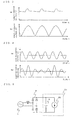
- behavior of the direct-current voltage which is an end-to-end voltage of the capacitor is determined. The operation waveforms are shown in Fig. 3.
- Figs. 3 are views illustrating relationships between capacities of a smoothing capacitor and rectified voltage waveforms.
- Fig. 3(a) illustrates a direct-current voltage waveform of a capacity (hereinafter, referred to as a conventional capacity) of a smoothing capacitor used in a conventional electric motor driving device. A variation of a pulsation of the voltage is small and accordingly, an output torque of an electric motor which is controlled by the conventional electric motor driving device can be controlled to be a substantially constant value.
- Fig. 3(b) illustrates a direct-current voltage waveform in the case where a smoothing capacitor having a capacity significantly reduced as compared with the conventional capacity or no capacitor is provided (hereinafter, referred to as capacity reduction).
- the direct-current voltage largely pulses due to the capacity reduction, and the waveform becomes a substantially similar form to a full wave rectified waveform of a power supply voltage. Therefore, if the electric motor is controlled similarly to the direct-current voltage shown in Fig. 3 (a), the torque is decreased when the direct-current voltage is largely decreased and the control becomes unstable around a power supply zero cross.
- the conventional capacity may be a value of, for example, about 1000 uF to 3000 uF, and the capacity in the capacity reduction may be a value of about 10 uF to 50 uF.
- the capacity of the smoothing capacity is C
- an inductance of the electric motor is L
- a rated current is I
- an allowable pulse quantity (variation) of direct-current voltage is V
- the conventional capacity and the reduced capacity are varied depending on the capacity of the electric motor and the allowable pulsation voltage, and the values are not limited to the above-described values. Further, it is to be noted that the calculation of the above approximate values is an approximate calculation, and a complete physical phenomenon is not completely represented by the above calculation method since the smoothing capacitor is charged by electric charges supplied from the single-phase alternating-current power supply.
- the capacity of the capacitor 3 which is provided at the direct-current output side of the first rectifying means is reduced to the capacity smaller than the capacity of the smoothing capacitor 8 which is provided at the output side of the second rectifying means. Then, as described above, the capacity is set such that the waveform of the direct-current voltage becomes substantially similar to the full wave rectified waveform of the power supply voltage.
- the capacitor 3 is connected to absorb noise generated due to switching of the inverter or a spike voltage.
- the present invention is not limited to the above, and a configuration which is not provided with the capacitor 3 may be employed.
- the first rectifying means 2 rectifies the output of the single-phase alternating-current power supply 1 and outputs the rectified power.
- the inverter main circuit 4 to which the rectified direct-current voltage is inputted is configured to switch the rectified output of the first rectifying means 2, converts the output into an alternating current output of a variable voltage and a variable frequency, and supplies the output to the electric motor 5 based on an operation signal inputted from the inverter control section 20.
- the capacity of the capacitor 3 is reduced to be small, and then, the direct-current voltage waveform outputted from the first rectifying means 2 to the inverter main circuit section 4 becomes, for example, the pulsation waveform shown in Fig. 3(b).
- the inverter control section 20 detects the current flowing into the electric motor 5 by a current detector 21, converts the detected current into a current value of a rotational orthogonal coordinate system in the coordinate conversion section 24 and outputs the value to the output voltage operation section 22.
- the output voltage operation section 22 performs an operation of an output voltage to be outputted to the electric motor 5 based on the inputted current value, and outputs an operation signal to the inverter main circuit section 4 in the PWM generation section 23.
- the output voltage operation section 22 calculates an output voltage to control an output torque to be synchronized with the form of the power supply voltage.
- the electric motor 5 is driven, and the output torque pulsation becomes the pulsation synchronized with the direct-current voltage of substantially similar form to the full wave rectified waveform of the power supply voltage.
- the current flowing in the electric motor 5 becomes a pulsating flow which is synchronized with the pulsation of the direct-current voltage shown in Fig. 4(b).
- the pulsation of the direct-current voltage is the waveform shown in Fig. 3(a)
- the current flowing in the electric motor becomes the current waveform which does not have a pulsating flow as shown in Fig. 4(a).
- the inverter main circuit section 4 and the electric motor 5 can be considered as a virtual current source.
- the virtual current source is described with reference to Fig. 5.
- Fig. 5 is a circuit block diagram for explaining the virtual current source according to the first embodiment of the present invention.
- a virtual current source 30 when the virtual current source 30 supplies an output current which is synchronized with the direct-current voltage, a parallel circuit 31 of the virtual current source 30 and the capacitor 3 function as resistance, since the capacity of the capacitor 3 is reduced to be small.
- the input current becomes a current of similar phase and a similar waveform to the voltage of the single-phase alternating-current power supply 1, and the harmonic current can be reduced.
- the inverter control section 20 detects power supply voltage information, for example, phase information of the power supply voltage, a zero point of the power supply voltage, an instantaneous value of the power supply voltage, an instantaneous pulsation voltage of the direct-current voltage, or the like. Then, the inverter control section 20 controls the electric motor 5 such that the current flowing into the inverter main circuit section 4 becomes a similar form to the single-phase alternating-current power supply 1 to achieve both the driving of the electric motor 5 and the harmonic current reduction control of the input current. As described above, when the inverter main circuit section 4 is controlled to be equivalent to the above-described virtual current source 30, even if the output torque pulsation exists, the electric motor 5 can be driven while reducing the harmonic current.
- power supply voltage information for example, phase information of the power supply voltage, a zero point of the power supply voltage, an instantaneous value of the power supply voltage, an instantaneous pulsation voltage of the direct-current voltage, or the like.
- a control voltage for the control circuit is generated from the end-to-end voltage of the smoothing capacitor, the voltage for the control circuit pulsates, and the control circuit may be inoperative. Further, if it is applied to an air conditioner, or the like, not only the control circuit but an actuator, an inverter for fan motor, or the like, which uses the direct-current voltage other than the electric motor may be inoperative or a noise oscillation due to the voltage pulsation may be increased.
- direct current load when the direct-current voltage to be supplied to such a control circuit, actuator, inverter for fan motor, or the like (hereinafter, referred to as direct current load) is required, in order to generate the control voltage, a smoothing capacitor for the direct current loads is further provided through a diode at an output side of rectifying means, and the direct-current voltage prevented from a voltage pulsation is generated.
- the rectifying means since the rectifying means is used in both purposes, a harmonic current which flows due to the power consumption of the direct-current loads is superposed on the current in the electric motor control. The superposition of the harmonic current components is described with reference to Figs. 6.
- Figs. 6 are views illustrating the current waveforms for explaining the superposition of the harmonic current components.
- the inverter control section can control the inverter such that a current like a resistance load flows.
- the rectifying means is used in the both purposes as described above, by the power consumed by the direct current load, the current flows only at peaks of the power supply voltage. Then, the input current shown in Fig. 6(b) flows.
- a current formed by synthesizing the both currents flows.
- a control of the electric motor is performed to prevent a prominence of the current in the vicinity of the current peaks
- the control of the current prominence is further to be performed in addition to the complicated control to perform both the electric motor control and the input current control, very complicated controls are to be performed, and then, the electric motor may not be driven or the harmonic current of the input current may not be reduced.
- the reactor and the smoothing capacitor resonate with each other, and the harmonic current increases due to the resonant frequency. Accordingly, if a reactor which has a large capacity is connected, the resonant frequency approximates tenfold of the power supply frequency.
- the second rectifying means 7 is provided at the input side of the first rectifying means 2 in parallel. Then, by separating the electric power system, the influence of the voltage pulsation to the direct current loads is eliminated.
- an air conditioner to which the electric motor driving device according to the present invention is applied is described with reference to Fig. 7.
- Fig. 7 is a view illustrating a structure of an air conditioner according to the first embodiment of the present invention.
- the electric motor 5 is disposed in a compressor 40 and drives the compressor 40.
- noise insulation measures are provided as the air conditioner against noise of the electric motor 5 such as a refrigerant gas noise caused at a time of compression of refrigerant.
- noise insulation measures of a fan 41 which is rotated by the fan motor 10 are such that the fan motor is installed through a rubber foot. Accordingly, the fan motor 10 is designed under conditions with respect to noise heard from the motor, stricter than those for a product design of the electric motor 5.
- the fan inverter 9 for driving the fan motor 10 is connected to the both ends of the smoothing capacitor 8 which is separated from the power system for controlling the drive of the electric motor 5.
- the smoothing capacitor 8 is set to have a sufficient capacity to store electric charge necessary for the fan motor 10. Accordingly, the end-to-end voltage of the smoothing capacitor 8 is stable without pulsation. Therefore, the noise due to the voltage pulsation directly heard from the fan motor 10 can be suppressed to a level equivalent to a state that the capacitor 3 has the conventional capacity. Further, since the direct-current voltage to be inputted to the control power supply generation section 11 which is connected to the both ends of the smoothing capacitor 8 is stabilized, the inverter control section 20 is prevented from becoming an inoperative state.
- Power consumption of the direct current load such as the actuator of the air conditioner, for example, the fan motor 10 is much smaller than that of the electric motor 5.
- the power consumption is about ten percent of the total of the power consumption of the air conditioner. Accordingly, if the rectifying means of the electric motor 5 and the direct current load are separated from each other, the current capacity of the second rectifying means 7 can be realized with the capacity smaller than that of the first rectifying means 2. Further, the reactor 6 which is connected in series between the single-phase alternating-current power supply 1 and the second rectifying means 7, to prevent the harmonic current of the current flowing from the single-phase alternating-current power supply 1 can be realized with very small current capacity.
- the harmonic current can be reduced and a resonant frequency with the smoothing capacitor 8 can be increased by using the small-capacity reactor, and the reactor of small and lightweight can be used. Further, the capacity of the smoothing capacitor 8 can be realized in a capacity smaller than that of the smoothing capacitor which has the conventional capacity.
- the power consumption line of the electric motor 5 can be configured to be separated from the other power consumption line by providing the second rectifying means 7 to independently reduce the both harmonic currents.
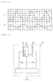
- Fig. 8 is a view illustrating a configuration of an electric motor driving device according to a second embodiment of the present invention.
- Figs. 9 are views illustrating current waveforms for explaining control of harmonic currents according to the second embodiment of the present invention.
- a switching section 50 which functions as harmonic current control means having a full wave rectifying circuit and a switching element is provided.
- a current capacity of the switching section 50 can be realized with a small capacity.
- a power factor of power supply is largely improved as compared to the case of the insertion of only the reactor 6. Then, current peaks of the harmonic current shown in Fig. 9(a) are suppressed as shown in Fig. 9(b), and the harmonic current due to the power consumed in the direct current load can be reduced.
- the switching section 50 is disposed at a position closer to the alternating current side than the second rectifying means 7. However, if the harmonic current can be suppressed, the switching section 50 may be disposed at either the alternating current side or the direct current side.
- Fig. 10 is a view illustrating a configuration of an electric motor driving device according to a third embodiment of the present invention.
- an insulation section 60 which insulates the inverter main circuit 4 and the inverter control section 20 is provided.
- the inverter control section 20 detects the current of the electric motor 5 and outputs an operation signal to the inverter main circuit section 4. Accordingly, it is necessary to use a reference potential (hereinafter, referred to as GND) common to the inverter main circuit section 4 and the inverter control section 20. Then, an input current harmonics are generated due to wraparound from the GDN. In order to block the wraparound current, the insulation section 60 is inserted to insulate the inverter main circuit section 4 from the inverter control section 20. Then, the input current harmonics due to the wraparound current from the GND can be blocked.
- GND reference potential
- Fig. 11 is a view illustrating a configuration of an electric motor driving device according to a fourth embodiment of the present invention.
- the reactor 6 is connected between the second rectifying means 7 and the single-phase alternating-current power supply 1.
- a reactor 70 is inserted between the first rectifying means 2 and the single-phase alternating-current power supply 1.
- the single-phase alternating-current power supply 1 has small impedance though it is very small. Accordingly, if the reactor 70 is inserted, resonance between the power supply impedance of the single-phase alternating-current power supply 1 and the capacitor 3 can be prevented. Further, if at a polar change of the power supply voltage, that is, just after zero cross, a rush current flows from the power supply, the rush current can be suppressed by the insertion of the reactor 70, and then, a harmonic current due to the rush current can also be prevented.
- the reactor 70 has a small-capacity inductance value.
- Fig. 12 is a view illustrating a configuration of an electric motor driving device according to a fifth embodiment of the present invention.
- an oscillation detector 80 which functions as oscillation detection means is provided on a surface of the compressor 40 which is driven by the electric motor 5.
- the oscillation detector 80 detects information about at least either of an oscillation amplitude and an oscillation frequency of the compressor 40 and inputs the detected information into the inverter control section 20. Functions having similar advantages to the above-described advantages are omitted in the drawings.
- the output torque of the electric motor 5 pulsates and the oscillation is generated. Then, noise is expected to be generated. Then, if a rotational frequency of the electric motor 5 corresponds to the oscillation frequency of the compressor 40, a mechanical resonance may be generated.
- a load torque due to a refrigerant compression of the compressor 40 also pulsates, the pulsation of the load torque and the pulsation of the output torque of the electric motor 5 cause a hunting, and a very large oscillation is generated correlatively with the mechanical resonance.
- the inverter control section 20 controls the rotational frequency of the electric motor 5 such that the rotational frequency of the electric motor 5 does not correspond to the oscillation frequency of the compressor 40 inputted from the oscillation detector 80.
- the correspondence of the frequency with the mechanical resonant frequency can be prevented; and the mechanical resonance can be suppressed.
- a configuration according to this embodiment is similar to that of the above embodiment 5.
- the inverter control section 20 controls the output torque of the electric motor 5 based on the oscillation amplitude and the oscillation frequency detected by the oscillation detector 80.
- the oscillation generated from the compressor 40 is described.
- the oscillation generated from the compressor 40 can be calculated using a transfer function of a mechanical system.
- the source of the oscillation is the electric motor 5.
- Tm an output torque to be outputted by the electric motor 5
- Tm the load torque due to the compression structure machine of the compressor connected to the electric motor 5
- Tm the load torque due to the compression structure machine of the compressor connected to the electric motor 5
- Tm 0. That is, the oscillation is generated in proportion to the difference of (Tm - T1). Accordingly, if the output torque is controlled in the inverter control section 20 such that the difference between the output torque Tm and the load torque T1 becomes zero, the oscillation can be prevented.
- FIG. 13(a) is the load torque of the compressor 40. With respect to the load torque of Fig. 13(a), the difference (Tm - T1) with respect to the output torque Tm is shown in Fig. 13(b).
- the inverter control section 20 controls the output of the inverter main circuit section 4 such that the phase of the oscillation waveform of the compressor 40 obtained based on the information about at least either of inputted oscillation amplitude and the oscillation frequency and the phase of the pulsation waveform of the output torque of the electric motor 5 become reversed phases with each other.
- the pulsation torque generated by reducing the capacity of the smoothing capacitor 3 to be small can be used for the oscillation prevention, and the pulsation torque can be effectively used.
- the oscillation detector 80 may be formed using an IC chip to integrate a battery and a radio IC to eliminate the wiring.
- the configuration has similar advantages.
- the IC chip may form the oscillation detector 80, for example, as shown in Fig. 14, using a semiconductor which detects capacitance variation with a mobile dielectric 81 and fixed electrodes 82. Then, the oscillation detector can be inexpensively formed as compared to conventional oscillation detectors.
- the oscillation frequency is detected using the oscillation detector 80.
- the oscillation detector 80 detects the oscillation.
- the oscillation detector 80 estimates the oscillation, also similar advantages can be obtained. For example, since the voltage to be applied to the electric motor 5 and the current flowing in the electric motor 5 are known, the inverter control section 20 can estimates the output torque Tm. Further, since the motor speed control is performed, the speed is known. If the estimated output torque and the known speed are used, the load torque T1 can also be estimated.
- the present invention can be applied to a product which has, as a form of the product, a compressor and a function, which consumes electric power, other than the compressor, for example, a dehumidifier, a refrigerator, a washing and drying machine, or the like. Further, the present invention can be applied, a product which has no compressor but an electric motor which consumes most of the electric power of the product and a function, which consumes electric power, other than the electric motor, for example, a cleaner, a washing and drying machine, or the like. Further, the similar advantages can be obtained in a product in which noise measurements against an electric motor which mainly consumes the electric power are sufficiently taken and an actuator which consumes a power from the direct-current voltage is mounted.
Applications Claiming Priority (2)
| Application Number | Priority Date | Filing Date | Title |
|---|---|---|---|
| JP2006070166 | 2006-03-15 | ||
| PCT/JP2006/324709 WO2007108185A1 (ja) | 2006-03-15 | 2006-12-12 | 電動機駆動装置及び圧縮機駆動装置 |
Publications (2)
| Publication Number | Publication Date |
|---|---|
| EP1871003A1 true EP1871003A1 (de) | 2007-12-26 |
| EP1871003A4 EP1871003A4 (de) | 2009-08-05 |
Family
ID=38522222
Family Applications (1)
| Application Number | Title | Priority Date | Filing Date |
|---|---|---|---|
| EP06834464A Ceased EP1871003A4 (de) | 2006-03-15 | 2006-12-12 | Motorantrieb und kompressorantrieb |
Country Status (5)
| Country | Link |
|---|---|
| EP (1) | EP1871003A4 (de) |
| JP (1) | JP4657301B2 (de) |
| CN (1) | CN101142738B (de) |
| AU (1) | AU2006335684C1 (de) |
| WO (1) | WO2007108185A1 (de) |
Cited By (2)
| Publication number | Priority date | Publication date | Assignee | Title |
|---|---|---|---|---|
| EP2667501A4 (de) * | 2011-01-18 | 2017-07-26 | Daikin Industries, Ltd. | Stromrichter |
| DE102021128779A1 (de) | 2021-11-05 | 2023-05-11 | Vaillant Gmbh | Verfahren zum Betreiben eines Elektromotors eines Verdichters einer Wärmepumpe, Computerprogramm, Speichermedium, Steuergerät und Wärmepumpe |
Families Citing this family (15)
| Publication number | Priority date | Publication date | Assignee | Title |
|---|---|---|---|---|
| JP5353188B2 (ja) * | 2008-11-04 | 2013-11-27 | ダイキン工業株式会社 | ヒートポンプ装置 |
| CN102345916B (zh) * | 2011-08-29 | 2013-11-20 | 深圳市锐钜科技有限公司 | 一种变频空调频率共振消除方法及系统 |
| JP5942809B2 (ja) * | 2012-11-19 | 2016-06-29 | トヨタ自動車株式会社 | 交流電動機の制御システム |
| JP6223915B2 (ja) * | 2014-06-20 | 2017-11-01 | 株式会社神戸製鋼所 | 圧縮機及びその駆動装置 |
| JP5931148B2 (ja) | 2014-09-10 | 2016-06-08 | ファナック株式会社 | 静電容量計算部を有するpwm整流器 |
| WO2016052215A1 (ja) * | 2014-10-01 | 2016-04-07 | 三菱電機株式会社 | 除湿機 |
| JP6247189B2 (ja) * | 2014-10-02 | 2017-12-13 | ファナック株式会社 | 直流リンク残留エネルギーの放電機能を有するモータ制御装置 |
| JPWO2018020657A1 (ja) * | 2016-07-29 | 2018-10-18 | 三菱電機株式会社 | 電力変換装置および空気調和装置 |
| JP6848778B2 (ja) * | 2017-09-15 | 2021-03-24 | オムロン株式会社 | 電力供給装置 |
| MY196768A (en) * | 2017-09-29 | 2023-05-03 | Daikin Ind Ltd | Power conversion device |
| JP6711859B2 (ja) * | 2018-04-04 | 2020-06-17 | ファナック株式会社 | モータ駆動装置およびモータ駆動装置の異常発熱検出方法 |
| CN109980995B (zh) * | 2018-06-01 | 2020-07-28 | 清华大学 | 转矩分配的方法、装置、计算机设备和存储介质 |
| WO2023067723A1 (ja) * | 2021-10-20 | 2023-04-27 | 三菱電機株式会社 | 電力変換装置、電動機駆動装置及び冷凍サイクル適用機器 |
| WO2023095264A1 (ja) * | 2021-11-25 | 2023-06-01 | 三菱電機株式会社 | 電力変換装置、モータ駆動装置及び冷凍サイクル適用機器 |
| WO2023105676A1 (ja) * | 2021-12-08 | 2023-06-15 | 三菱電機株式会社 | 電力変換装置、モータ駆動装置及び冷凍サイクル適用機器 |
Citations (2)
| Publication number | Priority date | Publication date | Assignee | Title |
|---|---|---|---|---|
| GB2257310A (en) * | 1991-05-31 | 1993-01-06 | Toshiba Kk | Inverter controlled air conditioner capable of effectively reducing in-rush current at starting |
| JPH06273029A (ja) * | 1993-03-16 | 1994-09-30 | Sharp Corp | 冷蔵庫 |
Family Cites Families (17)
| Publication number | Priority date | Publication date | Assignee | Title |
|---|---|---|---|---|
| JPH06153534A (ja) | 1992-10-30 | 1994-05-31 | Alex Denshi Kogyo Kk | コンデンサレス・インバータ装置とその制御方法 |
| JPH11514836A (ja) * | 1995-10-24 | 1999-12-14 | アクアガス ニュー ジーランド リミテッド | 交流−直流電源 |
| JPH10150795A (ja) | 1996-11-15 | 1998-06-02 | Toshiba Corp | インバータ装置 |
| JPH10174477A (ja) * | 1996-12-06 | 1998-06-26 | Hitachi Ltd | 電動機駆動装置及びこれを用いた空気調和機 |
| JP3424539B2 (ja) * | 1997-06-23 | 2003-07-07 | 三菱電機株式会社 | 電源高調波抑制装置 |
| JP2000125410A (ja) * | 1998-10-15 | 2000-04-28 | Mitsubishi Electric Corp | 電気自動車の制御装置 |
| JP2000188897A (ja) * | 1998-12-22 | 2000-07-04 | Sanyo Denki Co Ltd | モータ制御装置 |
| ATE268072T1 (de) * | 1999-09-01 | 2004-06-15 | Ramachandran Ramarathnam | Motorregler für unterschiedliche geschwindigkeiten |
| JP4493132B2 (ja) * | 1999-11-16 | 2010-06-30 | 三洋電機株式会社 | 電源装置 |
| JP2002051589A (ja) | 2000-07-31 | 2002-02-15 | Isao Takahashi | モータ駆動用インバータの制御装置 |
| JP4065375B2 (ja) * | 2001-11-20 | 2008-03-26 | 松下電器産業株式会社 | モータ駆動装置及びモータ駆動方法 |
| JP2004248395A (ja) * | 2003-02-13 | 2004-09-02 | Matsushita Electric Ind Co Ltd | モータ駆動装置 |
| US7292004B2 (en) * | 2003-04-14 | 2007-11-06 | Matsushita Electric Industrial Co., Ltd. | Motor driving apparatus |
| EP1646135A4 (de) * | 2003-07-15 | 2008-09-10 | Mitsubishi Electric Corp | Dreiphasen-stromwandler und stromwandler |
| JP3958265B2 (ja) * | 2003-08-22 | 2007-08-15 | 株式会社東芝 | 電気車制御装置 |
| JP4595427B2 (ja) | 2004-02-06 | 2010-12-08 | パナソニック株式会社 | 電力変換装置 |
| BRPI0512085A (pt) * | 2004-06-21 | 2008-02-06 | Toshiba Carrier Corp | aparelho de ar condicionado |
-
2006
- 2006-12-12 CN CN2006800083883A patent/CN101142738B/zh active Active
- 2006-12-12 AU AU2006335684A patent/AU2006335684C1/en active Active
- 2006-12-12 EP EP06834464A patent/EP1871003A4/de not_active Ceased
- 2006-12-12 JP JP2007538208A patent/JP4657301B2/ja active Active
- 2006-12-12 WO PCT/JP2006/324709 patent/WO2007108185A1/ja active Application Filing
Patent Citations (2)
| Publication number | Priority date | Publication date | Assignee | Title |
|---|---|---|---|---|
| GB2257310A (en) * | 1991-05-31 | 1993-01-06 | Toshiba Kk | Inverter controlled air conditioner capable of effectively reducing in-rush current at starting |
| JPH06273029A (ja) * | 1993-03-16 | 1994-09-30 | Sharp Corp | 冷蔵庫 |
Non-Patent Citations (1)
| Title |
|---|
| See also references of WO2007108185A1 * |
Cited By (2)
| Publication number | Priority date | Publication date | Assignee | Title |
|---|---|---|---|---|
| EP2667501A4 (de) * | 2011-01-18 | 2017-07-26 | Daikin Industries, Ltd. | Stromrichter |
| DE102021128779A1 (de) | 2021-11-05 | 2023-05-11 | Vaillant Gmbh | Verfahren zum Betreiben eines Elektromotors eines Verdichters einer Wärmepumpe, Computerprogramm, Speichermedium, Steuergerät und Wärmepumpe |
Also Published As
| Publication number | Publication date |
|---|---|
| AU2006335684B2 (en) | 2009-03-26 |
| JP4657301B2 (ja) | 2011-03-23 |
| AU2006335684C1 (en) | 2009-12-10 |
| JPWO2007108185A1 (ja) | 2009-08-06 |
| CN101142738A (zh) | 2008-03-12 |
| CN101142738B (zh) | 2010-12-22 |
| WO2007108185A1 (ja) | 2007-09-27 |
| EP1871003A4 (de) | 2009-08-05 |
| AU2006335684A1 (en) | 2007-10-04 |
Similar Documents
| Publication | Publication Date | Title |
|---|---|---|
| EP1871003A1 (de) | Motorantrieb und kompressorantrieb | |
| US8098035B2 (en) | Motor control unit | |
| KR100939164B1 (ko) | 다상 전류 공급 회로, 구동장치, 압축기 및 공기 조화기 | |
| CN105409111B (zh) | 电力变换装置以及使用电力变换装置的空气调节装置 | |
| EP2355329B1 (de) | Wechselstrom - gleichstrom wandler und elektromotor treiber | |
| EP1835607B1 (de) | Verfahren und Vorrichtung zur Gleichstromversorgung | |
| US8817505B2 (en) | Three-phase rectifier with bidirectional switches | |
| US20090168476A1 (en) | Bridgeless power factor correction circuit | |
| EP3176935B1 (de) | Stromwandlungsvorrichtung | |
| KR20040088356A (ko) | 모터 구동용 인버터 제어장치 및 그 인버터 제어장치를이용한 공기조화기 | |
| KR20160054011A (ko) | 직류 전원 장치 및 냉동 사이클 기기 | |
| WO2013099203A1 (ja) | モータインバータ装置 | |
| EP2333943B1 (de) | Netzstromkreis, Motorantriebsvorrichtung und Kühl- und Klimaanlage | |
| US9431888B1 (en) | Single-phase to three phase converter AC motor drive | |
| KR20140108956A (ko) | 전력변환장치 및 이를 포함하는 공기조화기 | |
| JP4572595B2 (ja) | コンバータ制御方法及びコンバータ制御装置並びに空調機及びその制御方法及び制御装置 | |
| JP5760446B2 (ja) | 電力変換装置 | |
| KR20110077801A (ko) | 직류전원 공급장치 및 직류전원 공급방법 | |
| JP2019080408A (ja) | 直流電源装置、及び空気調和機 | |
| WO2023095265A1 (ja) | 電力変換装置、モータ駆動装置および冷凍サイクル適用機器 | |
| KR102069067B1 (ko) | 리플 저감 정류부를 포함하는 전력 변환 장치 및 이를 포함하는 공기 조화기 | |
| CN116724484A (zh) | 电力转换装置、马达驱动装置和制冷循环应用设备 | |
| CN116724487A (zh) | 电力转换装置、马达驱动装置和制冷循环应用设备 | |
| JP2008099510A (ja) | 直流電源装置とそれを用いた機器 | |
| JPWO2022149210A5 (de) |
Legal Events
| Date | Code | Title | Description |
|---|---|---|---|
| PUAI | Public reference made under article 153(3) epc to a published international application that has entered the european phase |
Free format text: ORIGINAL CODE: 0009012 |
|
| 17P | Request for examination filed |
Effective date: 20071015 |
|
| AK | Designated contracting states |
Kind code of ref document: A1 Designated state(s): AT BE BG CH CY CZ DE DK EE ES FI FR GB GR HU IE IS IT LI LT LU LV MC NL PL PT RO SE SI SK TR |
|
| AX | Request for extension of the european patent |
Extension state: AL BA HR MK YU |
|
| RAX | Requested extension states of the european patent have changed |
Extension state: MK Extension state: BA Extension state: AL Extension state: HR Extension state: RS |
|
| RIN1 | Information on inventor provided before grant (corrected) |
Inventor name: ARISAWA, KOICHI Inventor name: SAKANOBE, KAZUNORI Inventor name: SHINOMOTO, YOSUKE Inventor name: YAMADA, MICHIO |
|
| DAX | Request for extension of the european patent (deleted) | ||
| RBV | Designated contracting states (corrected) |
Designated state(s): CH DE ES FR IT LI |
|
| A4 | Supplementary search report drawn up and despatched |
Effective date: 20090702 |
|
| 17Q | First examination report despatched |
Effective date: 20090826 |
|
| REG | Reference to a national code |
Ref country code: DE Ref legal event code: R003 |
|
| STAA | Information on the status of an ep patent application or granted ep patent |
Free format text: STATUS: THE APPLICATION HAS BEEN REFUSED |
|
| 18R | Application refused |
Effective date: 20161116 |