EP1867787A2 - Schneeschleuder - Google Patents
Schneeschleuder Download PDFInfo
- Publication number
- EP1867787A2 EP1867787A2 EP07108397A EP07108397A EP1867787A2 EP 1867787 A2 EP1867787 A2 EP 1867787A2 EP 07108397 A EP07108397 A EP 07108397A EP 07108397 A EP07108397 A EP 07108397A EP 1867787 A2 EP1867787 A2 EP 1867787A2
- Authority
- EP
- European Patent Office
- Prior art keywords
- snow
- body frame
- coupling bracket
- removing unit
- cam
- Prior art date
- Legal status (The legal status is an assumption and is not a legal conclusion. Google has not performed a legal analysis and makes no representation as to the accuracy of the status listed.)
- Granted
Links
Images






Classifications
-
- E—FIXED CONSTRUCTIONS
- E01—CONSTRUCTION OF ROADS, RAILWAYS, OR BRIDGES
- E01H—STREET CLEANING; CLEANING OF PERMANENT WAYS; CLEANING BEACHES; DISPERSING OR PREVENTING FOG IN GENERAL CLEANING STREET OR RAILWAY FURNITURE OR TUNNEL WALLS
- E01H5/00—Removing snow or ice from roads or like surfaces; Grading or roughening snow or ice
- E01H5/04—Apparatus propelled by animal or engine power; Apparatus propelled by hand with driven dislodging or conveying levelling elements, conveying pneumatically for the dislodged material
-
- E—FIXED CONSTRUCTIONS
- E01—CONSTRUCTION OF ROADS, RAILWAYS, OR BRIDGES
- E01H—STREET CLEANING; CLEANING OF PERMANENT WAYS; CLEANING BEACHES; DISPERSING OR PREVENTING FOG IN GENERAL CLEANING STREET OR RAILWAY FURNITURE OR TUNNEL WALLS
- E01H5/00—Removing snow or ice from roads or like surfaces; Grading or roughening snow or ice
- E01H5/04—Apparatus propelled by animal or engine power; Apparatus propelled by hand with driven dislodging or conveying levelling elements, conveying pneumatically for the dislodged material
- E01H5/08—Apparatus propelled by animal or engine power; Apparatus propelled by hand with driven dislodging or conveying levelling elements, conveying pneumatically for the dislodged material dislodging essentially by driven elements
- E01H5/09—Apparatus propelled by animal or engine power; Apparatus propelled by hand with driven dislodging or conveying levelling elements, conveying pneumatically for the dislodged material dislodging essentially by driven elements the elements being rotary or moving along a closed circular path, e.g. rotary cutter, digging wheels
- E01H5/098—Apparatus propelled by animal or engine power; Apparatus propelled by hand with driven dislodging or conveying levelling elements, conveying pneumatically for the dislodged material dislodging essentially by driven elements the elements being rotary or moving along a closed circular path, e.g. rotary cutter, digging wheels about horizontal or substantially horizontal axises perpendicular or substantially perpendicular to the direction of clearing
Definitions
- the present invention relates to a snow blower.
- a snow blower includes a traveling body and a snow-removing unit disposed forward of the traveling body.
- the snow-removing unit includes an auger casing and a substantially cylindrical blower housing extended rearward from a lateral center portion of the auger casing.
- a laterally axial snowplowing auger is disposed rotatably so as to plow snow rearward to a blower in the blower housing.
- the blower in the blower housing rotates to blow out the plowed snow.
- the traveling body includes a substantially rectangular parallelepiped body frame incorporating a transmission and others.
- the blower housing is fastened to the body frame by bolts so as to connect the snow-removing unit to the front end of the traveling body.
- a box-shaped bracket having a rear opening is disposed on a rear surface of the blower housing, and is inserted into a front opening of the body frame. Then, the bracket inserted in the body frame is fastened at a peripheral edge thereof to the body frame by bolts.
- the box-shaped bracket has a large area contacting the body frame so as to strongly support the snow-removing unit onto the body frame.
- many bolts are required to fasten the bracket to the body frame. Further, if the bolts are screwed up by different forces, the bracket may deviate from its proper position corresponding to the body frame.
- JP 2005-200880 A discloses a snow blower which employs another conventional structure for supporting a snow-removing unit onto a body frame.
- a rear surface of a blower housing of the snow-removing unit is provided with no bracket, and is directly fixed to a front end of the body frame by welding or the like.
- the joint between the blower housing and the body frame by welding or the like is strong, and is economic because it requires no fastening member such a bolt.
- the snow-removing unit is supplied with power for driving a snowplowing auger and a blower therein from a prime mover on the body frame through a belt passed through the front opening of the body frame. Since the snow-removing unit is not detachable from the body frame, the belt cannot be easily exposed for maintenance or repairing.
- An object of the invention is to provide a snow blower having a simplified structure for detachably coupling a snow-removing unit to a body frame with a sufficient strength, wherein the snow-removing unit can be surely attached to the body frame at its proper position every time it is coupled to the body frame.
- a snow blower comprises a body frame and a snow-removing unit.
- the snow-removing unit is separable from the body frame, and is fixedly provided with a coupling bracket to be coupled to the body frame.
- First engagement means is provided at any of upper, lower, left and right portions of the coupling bracket.
- Second engagement means is provided at any of upper, lower, left and right portions of the body frame in correspondence to the first engagement means.
- First fixture means is provided at any other of the upper, lower, left and right portions of the coupling bracket.
- Second fixture means is provided at any other of the upper, lower, left and right portions of the body frame in correspondence to the first fixture means.
- the first and second fixture means match with each other without deviation so as to surely couple the snow-removing unit to the body frame at a proper position.
- the portion for the first and second engagement means is different from the portion for the first and second fixture means, so as to ensure the strength of the body frame supporting the snow-removing bracket.
- the snow blower requires only the small number of fastening members provided to the matching first and second fixture means.
- one of the first and second engagement means is a groove, and the other of the first and second engagement means is a member to be engaged into the groove. Therefore, the first and second engagement means can be provided simply and inexpensively.
- the first and second fixture means are holes through which a fastening member for fixing the coupling bracket to the body frame is passed when the holes serving as the first and second fixture means coincide to each other.
- the fastening member may be a bolt. Therefore, the first and second fixture means can be provided simply and inexpensively. Due to the first and second engagement means, the holes serving as the first and second fixture means and the fastening member are reduced in the number of components and manufacturing processes.
- a snow blower comprises a body frame and a snow-removing unit.
- the snow-removing unit includes a coupling bracket to be coupled to the body frame.
- the coupling bracket and the body frame are provided at one of left and right sides thereof with pivotal connection means which pivotally connects the coupling bracket and the body frame to each other.
- the coupling bracket and the body frame are separable from each other at the other of the left and right sides thereof so that the separable sides of the coupling bracket and the body frame are rotated relative to each other centered on the pivotal connection means so as to engage or disengage with and from each other.
- the snow-removing unit merely has to be rotated relative to the body frame, and does not have to be lifted up or down. Only the separable sides of the coupling bracket and the body frame are required to be fixed to each other when the snow-removing unit is attached to the body frame.
- first and second fixture means are provided on the separable sides of the coupling bracket and the body frame so as to match with each other when the separable sides of the coupling bracket and the body frame engage with each other. Only the separable sides of the coupling bracket and the body frame are required to be provided with the first and second fixture means, thereby reducing the number of components or manufacturing processes.
- a power transmission system for the snow-removing unit is provided on a side of the snow-removing unit on which the coupling bracket is disposed, so that the power transmission system is drivingly connected to a prime mover on the body frame when the coupling bracket of the snow-removing unit is completely coupled to the body frame, and so that the power transmission system remains on the side of the snow-removing unit when the coupling bracket is separated or rotated away from the body frame. Therefore, the power transmission system for the snow-removing unit can be easily exposed for facilitating maintenance or repairing.
- the power transmission system includes a snow-removing input pulley, a belt looped over the snow-removing input pulley, a belt guide for the belt, and a tension pulley for the belt. Therefore, such a belt type transmission system, serving as the power transmission system for the snow-removing unit, can be easily exposed for facilitating maintenance or repairing.
- Fig. 1 is an entire side view of a snow blower.
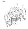
- Fig. 2 is a perspective front view of a snowplowing auger in a snow-removing unit of the snow blower.
- Fig. 3 is a sectional side view of a gearbox drivingly connecting a blower shaft to an auger shaft.
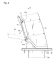
- Fig. 4 is a side view of a portion of the snow-removing unit around a chute.
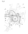
- Fig. 5 is a perspective view of a body frame and a blower housing provided with respective coupling portions to be connected to each other according to a first embodiment while they are separated from each other.
- Fig. 6 is a side view of the body frame and the blower housing according to the first embodiment when they are connected to each other.
- Fig. 7 is a rear view of the coupling portion of the blower housing according to the first embodiment.
- Fig. 8 is a side view of the coupling portions of the blower housing and the body frame according to the first embodiment when they are separated from each other.
- Fig. 9 is a plan view of the coupling portions of the blower housing and the body frame according to the first embodiment when they are separated from each other.
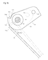
- Fig. 10 is a plan view of a body frame and a blower housing adapted to be connected to each other according a second embodiment.
- Fig. 11 is a fragmentary rear view of the snow blower showing left and right steering handles with a locking mechanism.
- Fig. 12 is an enlarged rear view of the locking mechanism.
- Fig. 13 is a fragmentary left side view of the snow blower showing the right steering handle with the locking mechanism.
- Fig. 14 is an enlarged left side view of the locking mechanism set for clutching off a traveling clutch and a snow-removing clutch.
- Fig. 15 is an enlarged right side view of the locking mechanism in the state of Fig. 14.
- Fig. 16 is an enlarged left side view of the locking mechanism set for clutching on the traveling clutch and the snow-removing clutch.
- Fig. 17 is an enlarged right side view of the locking mechanism in the state of Fig. 16.
- Fig. 18 is an enlarged left side view of the locking mechanism when a traveling clutch lever is released from a gripping force after the state of Figs. 16 and 17.
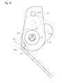
- Fig. 19 is an enlarged right side view of the locking mechanism in the state of Fig. 18.
- FIGs. 1 to 3 an entire structure of a snow blower 1 having a coupling structure according to a first embodiment will be described, on the assumption that snow blower 1 faces forward as directed by an arrow A shown in Figs. 1 to 3, so that left and right sides of snow blower 1 are designated based on the A-arrowed direction.
- snow blower 1 comprises a snow-removing unit 11, a drive unit 12, a traveling unit 13, and an operation unit 14.
- Drive unit 12, traveling unit 13 disposed under drive unit 12, and operation unit 14 disposed behind drive unit 12 constitutes a main body of snow blower 1.
- Snow-removing unit 11 is disposed in front of the main body.
- the main body includes a body frame 15.
- Snow-removing unit 11 includes a blower housing 16 and an auger housing 18 disposed on a front end of blower housing 16.
- Blower housing 16 and body frame 15 have respective coupling portions adapted to be connected to each other, as detailed later, so as to connect snow-removing unit 11 to the main body.
- blower housing 16 incorporates a blower (not shown), which is provided on a fore-and-aft horizontal blower shaft 41 so as to be driven by blower shaft 41.
- Auger housing 18 covers a snowplowing auger 19 and supports a lateral horizontal auger shaft 42 serving as a rotary shaft of snowplowing auger 19.
- Blower shaft 41 is extended forward from blower housing 16 and is drivingly connected to auger shaft 42, as detailed later.
- Blower housing 16 is formed with a cylindrical delivery port 16a projecting upward from a laterally eccentric portion thereof.
- a chute 21 is horizontally swivellably fitted at a bottom end thereof onto a top of delivery port 16a through a lock (shake proof) washer 20.
- Chute 21 is provided with a lock device (not shown) which locks chute 21 onto lock washer 20 at an optional direction.
- an outer peripheral edge of lock washer 20 is toothed so as to mesh with a gear drivingly connected to a motor. The motor is driven to rotate chute 21 together with lock washer 20 through the gear, thereby changing the direction of snow thrown from a top opening of chute 21.
- a manually operable chute handle for controlling the snow-throwing direction may be extended from chute 21 rearward to operation unit 14.
- Snow-removing unit 11 is configured so that snowplowing auger 19 plows and collects snow to a lateral center portion thereof, the blower blows the collected snow upward, and chute 21 guides the blown snow in an optional direction and exhausts it.
- a cap 17 having the top opening is vertically rotatably supported on the top of chute 21. Due to the vertical rotation of cap 17, the snow-throwing distance from chute 21 can be adjusted.
- a tension spring 34 is interposed between cap 17 and chute 21 so as to bias cap 17 upward.
- a link plate 27 is pivoted on cap 17, and a wire 30 is extended from link plate 27 so as to be connected to a chute operation lever 36 provided on operation unit 14.
- chute operation lever 36 When chute operation lever 36 is rotatably operated, cap 17 is rotated against spring 34 so as to control the snow-throwing distance.
- a motor may be provided for rotating cap 17, and a switch for controlling the drive of the motor may be disposed at operation unit 14.
- chute 21 is provided with a chute guard 43 for preventing a hand or a snow-removing rod for removing snow from entering chute 21.
- Chute guard 43 will be described with reference to Fig. 4, on the assumption that snow blower 1 faces forward in A-arrowed direction.
- Chute 21 is gently bent forwardly upward when viewed in side, and is U-shaped bent when viewed in plan so as to have a front opening.
- Chute guide 43 is substantially rectangular when viewed in front, and is U-shaped bent when viewed in plan so as to have a rear opening.
- Chute guard 43 is disposed on the inside of a lower front portion of chute 21.
- a fulcrum shaft 74 projects laterally outward from a bottom portion of each of left and right side surfaces of chute guard 43, and an engagement shaft 75 projects laterally outward from a top portion of each of left and right side surfaces of chute guard 43.
- Upper and lower grooves 21a are formed in a front edge of each of left and right side surfaces of chute 21, so as to receive respective shafts 74 and 75 thereinto, thereby holding chute guard 43 onto chute 21.
- Each groove 21a is substantially vertically reversed L-shaped when viewed in side, so as to have a front open end, a substantially horizontal portion, and a substantially vertical portion extended downward from a rear end of the substantially horizontal portion.
- the substantially vertical portion of lower groove 21a is longer than that of upper groove 21a, so that fulcrum shaft 74 can remain in the substantially vertical portion of lower groove 21a even if engagement shaft 75 is removed from the substantially vertical portion of upper groove 21a and is disposed in the substantially horizontal portion of upper groove 21a.
- chute guard 43 is settled to cover the front opening of chute 21.
- chute guard 43 is slightly raised so as to move shafts 74 and 75 to top ends of the substantially vertical portions of grooves 21a. Then, chute guard 43 is rotated at the top portions thereof forwardly downward centered on fulcrum shaft (or shafts) 74 by an operator's hand, so as to remove engagement shaft (or shafts) 75 from the front open ends of upper grooves 21a, and to widely open the front opening of chute 21.
- Fulcrum shaft (or shafts) 74 also can be removed from lower grooves 21a, i.e., chute guard 43 can be completely separated from chute 21, so as to further widely open the front opening of chute 21. Then, an operator's hand is directly inserted into chute 21 through the front opening, or a handled snow-removing rod is inserted into chute 21, so as to remove snow from the inner space of chute 21.
- a conventional chute guard 44 disposed to cover the front opening of chute 21 is drawn in bold phantom lines.
- the sectional area surrounded by chute 21 with chute guard 44 is substantially constant in the vertical direction.
- chute guard 44 has upper and lower end portions which are spaced at equal distances X and Y from the inside surface of the rear end portion of chute 21. Consequently, chute guard 44 is extended substantially vertically so that snow (especially, damp snow) likely sticks on the inside surface of chute guard 44 so as to cause choking of chute 21.
- the present chute guard 43 has a front side portion which is slanted forwardly upward at an angle ⁇ from the vertical direction when chute guard 43 is disposed to cover the front opening of chute 21. Due to the slope of chute guard 43, chute 21 is hardly choked with snow, thereby smoothly exhausting snow.
- blower shaft 41 for driving the blower receives power from drive unit 12, and auger shaft 42 for driving snowplowing auger 19 is driven by blower shaft 41.
- a drive system in drive unit 12 for driving blower shaft 41 will be described with reference to Figs. 1 to 3 and 5.
- the transmission for driving traveling unit 13 is disposed inside of body frame 15.
- An engine 22 is mounted upward on body frame 15.
- An engine output shaft projects forward from engine 22.
- a traveling output pulley and a snow-removing output pulley are provided on the engine output shaft.
- a later-discussed traveling clutch may be interposed between the engine output shaft and the traveling output pulley and be operatively connected to a later-discussed traveling clutch lever 35, and a later-discussed snow-removing clutch may be interposed between the engine output shaft and the snow-removing output pulley and be operatively connected to a later-discussed snow-removing clutch lever 39.
- a traveling input pulley of the transmission is disposed in a front portion of body frame 15, and a traveling belt is interposed between the traveling output and input pulleys so as to transmit power from engine 22 to traveling unit 13.
- a snow-removing belt 29 is looped over the snow-removing output pulley to transmit power to snow-removing unit 11.
- a belt cover 80 covers the traveling output pulley, the snow-removing output pulley and upper portions of the traveling belt and snow-removing belt 29.
- a rear end of blower shaft 41 projects rearward from snow-removing unit 11, i.e., blower housing 16, and a snow-removing input pulley 28 is fixed on the rear end of blower shaft 41.
- a belt guide 81 is fixed on a rear surface of snow-removing unit 11, i.e., blower housing 16, along a lower peripheral portion of snow-removing input pulley 28 so as to guide snow-removing belt 29 looped over snow-removing input pulley 28.
- Belt guide 81 prevents snow-removing belt 29 being driven by engine 22 from escaping from snow-removing input pulley 28. Further, while snow-removing unit 11 is separated from the main body for maintenance, belt guide 81 prevents snow-removing belt 29 (having removed from the snow-removing output pulley on the main body) from escaping, thereby facilitating the maintenance.
- a tension arm 82 is pivoted at a lower portion thereof onto the rear surface of blower housing 16, and a tension pulley 40 is pivoted on a top portion of upwardly extended tension arm 82 so as to be applied onto snow-removing belt 29.
- Tension arm 82 may be operatively connected to later-discussed snow-removing clutch lever 39 so as to serve as the later-discussed snow-removing clutch with tension pulley 40.
- a coupling bracket 46 is fixed on the rear surface of snow-removing unit 11, i.e., blower housing 16, so as to cover top, left and right portions of snow-removing input pulley 28, thereby further facilitating the maintenance.
- snow-removing input pulley 28 When snow-removing unit 11 is connected to the main body, snow-removing input pulley 28 is disposed inside of body frame 15, snow-removing belt 29 having been looped over snow-removing input pulley 29 is looped over the snow-removing output pulley so that tension pulley 40 applies tension to snow-removing belt 29, and then, belt cover 80 is provided to cover snow-removing belt 29.
- the belt transmission system for snow-removing unit 11, i.e., for driving blower shaft 41 is disposed between the main body and snow-removing unit 11, i.e., blower housing 16.
- a chain and sprockets, or a gear train may constitute a power transmission system for transmitting power from engine 22 to blower shaft 41.
- a gearbox 2 is provided on the front end of blower shaft 41 in auger housing 18 so as to transmit power from blower shaft 41 to auger shaft 42, thereby driving snowplowing auger 19.
- the front end of blower shaft 41 is journalled by front and rear bearings 5, and a warm 3 is spline-fitted on blower shaft 41 between bearings 5.
- a warm wheel 4 is fixed on a lateral center portion of auger shaft 42, and is disposed under the front end of blower shaft 41 so as to mesh with warm 3.
- a front collar 6 is disposed on blower shaft 41 between front bearing 5 and warm 3
- a cushion 7 and a flanged rear collar 8 are disposed on blower shaft 41 between warm 3 and rear bearing 5, so as to fix the axial position of warm 3 on blower shaft 41.
- Cushion 7 is made of elastic material such as rubber. While blower shaft 41 and warm 3 are rotated, warm wheel 4 rotated according to the rotation of warm 3 thrusts warm 3 axially rearward. In case that auger shaft 42 having been rotated is unexpectedly locked by contamination or for another reason, cushion 7 cushions warm 3 intended to slide rearward. Such a simple cushion 7 protects the warm gear assembly.
- the transmission disposed in body frame 15 has the traveling input shaft which receives power from engine 22 through the traveling belt.
- a front portion of body frame 15 rotatably supports a lateral horizontal front drive axle 23 driven by the transmission.
- a pair of left and right drive sprockets 25 are fixedly fitted on left and right outer ends of drive axle 23.
- a rear portion of body frame 15 rotatably supports a lateral horizontal rear axle 24.
- a pair of left and right follower sprockets 26 are fixedly fitted on left and right outer ends of rear axle 24.
- a left crawler belt 31 is looped over left sprockets 25 and 26, and a right crawler belt 31 is looped over right sprockets 25 and 26, so as to be driven by rotation of drive axle 23.
- Operation unit 14 will be described with reference to Fig. 1.
- a pair of left and right steering handles 32 are extended upwardly rearward from left and right rear potions of body frame 15 so as to be gripped by an operator standing behind snow blower 1.
- An operation box 33 is disposed between steering handles 32 when viewed in plan.
- On operation box 33 are provided a traveling clutch lever 35, a snow-removing clutch lever 39, chute operation lever 36, an engine speed control lever 37, a traveling speed control lever 38 and so on.
- Traveling clutch lever 35 is provided for clutching on/off of the power transmission from engine 22 to traveling unit 13.
- Snow-removing clutch lever 39 is provided for clutching on/off of the power transmission from engine 22 to snow-removing unit 11.
- Chute operation lever 36 is provided for controlling the vertical rotation position of cap 17, as mentioned above.
- Engine speed control lever 37 is provided for controlling the rotary speed of engine 22.
- Traveling speed control lever 38 is provided for speed-control of the transmission of traveling unit 13.
- Traveling clutch lever 35 and snow-removing clutch lever 39 are dead-man clutches, which are disposed forwardly upward of respective left and right steering handles 32 and biased to respective clutch-off positions thereof. Traveling clutch lever 35 is set at a clutch-on position thereof for driving sprockets 25 when it is gripped together with left steering handle 32. Snow-removing clutch lever 39 is set at a clutch-on position thereof for driving blower shaft 41 (and auger shaft 42) when it is gripped together with right steering handle 32. If snow-removing clutch lever 39 is gripped while traveling clutch lever 35 is gripped, snow-removing clutch lever 39 is locked at the clutch-on position.
- a locking mechanism 50 for locking snow-removing clutch lever 39 is detailed later with reference to Figs. 11 to 19.
- a structure for coupling snow-removing unit 11 to the main body will be described with reference to Figs. 5 to 10, on the assumption that snow blower 1 faces forward as directed by arrow A shown in Figs. 5 to 10, so that left and right sides of snow blower 1 are designated based on the A-arrowed direction.
- Body frame 15 is entirely substantially rectangular parallelepiped, so as to have a horizontal top plate portion and vertical left and right plate portions. Further, as shown in Figs. 5 and 9, body frame 15 has a vertical front opening, and has an opening 47, which is formed at a front portion of the horizontal top plate portion so as to be continued from the front opening.
- Coupling bracket 46 is fixed onto the rear surface of blower housing 16 disposed at the rear end of snow-removing unit 11. As best shown in Fig. 7, coupling bracket 46 is a plate bent into a vertically reversed U-shape when viewed in rear, so as to have a horizontal top plate portion 46a and a pair of vertical left and right side plate portions 46b. Further, top, left and right plate portions 46a and 46b of coupling bracket 46 are L-like bent inward at front ends thereof so as to have respective lateral vertical plate portions joined to the rear surface of blower housing 16.
- coupling bracket 46 is fitted onto outer surfaces of the front edge of body frame 15, i.e., top plate portion 46a and left and right plate side portions 46b are fitted onto top, left and right outer surfaces of the front edge of body frame 15.
- the front edge of body frame 15 is inserted into coupling bracket 46.
- one of left and right plate side portions 46b (in this embodiment, right side plate portion 46b) is bent at a rear end thereof laterally outward so as to have a guide plate portion 46c for easily inserting the front edge of body frame 15 into coupling bracket 46.
- coupling bracket 46 is provided with first engagement means at any of upper, lower, left and right portions thereof, and body frame 15 is provided with second engagement means at any of upper, lower, left and right front portions thereof so as to engage with the first engagement means of coupling bracket 46.
- coupling bracket 46 is provided with first fixture means at any other of the upper, lower, left and right portions thereof, and body frame 15 is provided with second fixture means at any other of the upper, lower, left and right portions thereof in correspondence to the first fixture means of coupling bracket 46.
- the first and second fixture means match with each other for fixing coupling bracket 46 to body frame 15.
- a fastening member is fitted to the mutually matching first and second fixture means so as to fix coupling bracket 46 to body frame 15.
- coupling bracket 46 is provided with a pair of left and right pins 49, serving as first engagement means 77, at respective left and right upper portions thereof. More specifically, left and right pins 49, having coaxial lateral horizontal axes and circular shapes in section, are fitted through upper portions of respective left and right side plate portions 46b, and are fixed to a lower surface of top plate portion 46a so as to serve as left and right first engagement means 77. Alternatively, a single pin which is as long as or longer than the lateral distance between left and right side plate portions 46b of coupling bracket 46 may be spanned between left and right side plate portions 46b so as to serve as the first engagement means.
- Body frame 15 is provided with a pair of left and right upwardly opened grooves 48, serving as the second engagement means, at respective left and right upper portions thereof.
- Coupling bracket 46 is provided with a pair of left and right bolt holes 72, serving as the first fixture means, at left and right lower portions thereof.
- Body frame 15 is provided with a pair of left and right bolt holes 70, serving as the second fixture means, at respective left and right lower portions thereof.
- snow-removing unit 11 When snow-removing unit 11 is going to be connected to the main body, firstly, snow-removing unit 11 is lifted up by the vertical width of pins 49, and left and right pins 49 are put on left and right horizontal top edges of the front portion of body frame 15 having opening 47 therebetween. Then, snow-removing unit 11 is slid rearward (i.e., toward the main body) so as to slide left and right pins 49 backward on the left and right top edges of the front portion of body frame 15. During this slide of pins 49, left and right side plate portions 46b of coupling bracket 46 slides rearward against the left and right side surface of body frame 15. Finally, pins 49 fall into respective grooves 48, so as to completely engage the first engagement means with the second engagement means.
- bolt holes 72 naturally come to coincide to respective bolt holes 70, i.e., the first and second fixture means match with each other. Then, the bolts are screwed through coinciding bolt holes 72 and 70, so as to completely fix snow-removing unit 11 to body frame 15.
- snow-removing unit 11 when snow-removing unit 11 is going to be disconnected from the main body, firstly, the bolts are removed from respective coinciding bolt holes 72 and 70, and snow-removing unit 11 is raised so as to remove pins 49 upward from respective grooves 48. Then, snow-removing unit 11 is moved forward so as to slide left and right pins 49 forward on the left and right top edges of the front portion of body frame 15 having opening 47 therebetween in front of respective grooves 48, thereby completely removing coupling bracket 46 forward from body frame 15.
- snow-removing input pulley 28 fixed on blower shaft 41, snow-removing belt 29, tension pulley 40 and the like are exposed on the rear portion of snow-removing unit 11, i.e., blower housing 16, thereby facilitating their maintenance.
- the front portion of body frame 15 is opened so as to facilitate maintenance of the traveling power transmission system to the traveling input shaft of the transmission disposed in body frame 15.
- Pins 49 are joined to top plate portion 46a of coupling bracket 46 by welding or the like, so as to have sufficient strengths against frequent shock or load generated upward from the ground, thereby ensuring sufficient strength in supporting snow-removing unit 11 onto the main body when snow-removing unit 1 is coupled to the main body. Further, pins 49 have slidability against the left and right top edges of body frame 15, so as to be smoothly guided into respective grooves 48, thereby facilitating connection and disconnection of snow-removing unit 11 to and from the main body.
- a groove or grooves may serve as the first engagement means of coupling bracket 46, and a member or members, such as a pin or pins, to be fitted into the groove or grooves, may serve as the second engagement means of body frame 15.
- the groove or grooves on coupling bracket 46 is/are downwardly opened, so that coupling bracket 46 having been raised is lowered to catch the member or members into the groove or grooves.
- first and second engagement means may be provided at lower portions of coupling bracket 46 and body frame 15.
- body frame 15 is formed in the corresponding left or right side portion thereof with at least one vertically reversed L-shaped groove having an opened front end, a horizontal portion extended rearward from the front end, and a vertical portion extended downward from a rear end of the horizontal portion.
- the pin falls into the vertical portion of the groove and reaches the bottom of the vertical portion of the groove, so as to completely engage the first engagement means with the second engagement means.
- first and second fixture means e.g., bolt holes, may be provided at upper portions of coupling bracket 46 and body frame 15, so as to match with each other for fixing coupling bracket 46 to body frame 15 when the pin reaches the bottom of the vertical portion of the groove.
- snow-removing unit 11 with coupling bracket 46 can be completely separated from body frame 15.
- snow-removing unit 11 with a coupling bracket 45 is constantly pivotally connected at one of left and right sides thereof to a body frame 9, so as to be separable from body frame 9 at the other of the left and right sides thereof.
- the second embodiment shown in Fig. 10 will be described on the assumption that snow blower 1 faces forward as directed by an arrow A shown in Fig. 10, so that left and right sides of snow blower 1 are designated based on the A-arrowed direction.
- coupling bracket 45 and body frame 9 are provided at one of left and right sides (in this embodiment, left side) thereof with pivotal connection means pivotally connecting coupling bracket 45 and body frame 9 to each other through a vertical pivot shaft 73, so that coupling bracket 45 and body frame 9 are separable from each other at the other of the left and right sides (in this embodiment, right side) thereof.
- the pivotal connection means may be a hinge or hinges.
- a guide portion 45a is formed on the right side of coupling bracket 45, and a slanted surface 9a is formed on the right side of body frame 9.
- guide portion 45a has an edge slanted laterally outwardly rearward, and slanted surface 9a is slanted laterally inwardly forward.
- the right side portions of coupling bracket 45 and body frame 9 are formed (or fixedly provided) with a pin and a guide groove, respective, so that the pin is inserted into the guide groove when coupling bracket 45 is rotated to be coupled to body frame 9.
- the right side portions of coupling bracket 45 and body frame 9 are formed with respective bolt holes which coincide to each other when the right side portion of coupling bracket 45 is completely located at the proper coupling position relative to the right side front portion of body frame 9. A bolt serving as a fastening member is inserted through the coinciding bolt holes of coupling bracket 45 and body frame 9, thereby completely fixing snow-removing unit 11 to body frame 9.
- coupling bracket 45 and body frame 9 serve as fixture portions to be fixed to each other through the fastening member, the fastening members can be reduced in number in comparison with those for coupling bracket 46 and body frame 15 of the first embodiment, which have left and right fixture portions to be fixed to each other through the respective left and right fastening members.
- Locking mechanism 50 for locking snow-removing clutch lever 39 will be detailed with reference to Figs. 11 to 15. As shown in Figs. 11 and 12, locking mechanism 50 includes a first rotary shaft 51, a second rotary shaft 52 disposed coaxially to first rotary shaft 51, a boss 65 interposed between first and second rotary shafts 51 and 52, a traveling clutch operation plate cam 53, a snow-removing clutch operation plate cam 54, a spring rod 55, and left and right shaft-supporting brackets 56a and 56b fixed on respective left and right steering handles 32.
- First rotary shaft 51 (preferably, made of a steel shaft) is extended laterally horizontally.
- One (left) end of first rotary shaft 51 is rotatably supported by bracket 56a fixed on one (left) steering handle 32 provided with traveling clutch lever 35.
- the other (right) end 51a of first rotary shaft 51 is relatively rotatably fitted into an axial hole 65a of boss 65.
- a connection plate 35a is fixedly provided on a laterally inside portion of traveling clutch lever 35, and is relatively unrotatably connected to first rotary shaft 51. Due to this connection, when traveling clutch lever 35 is rotated, i.e., when traveling clutch lever 35 is gripped together with left steering handle 32 or is released from a hand, first rotary shaft 51 is rotated together with traveling clutch lever 35.
- Second rotary shaft 52 (preferably, made of a steel shaft) is extended laterally horizontally coaxially to first rotary shaft 51.
- One (right) end of second rotary shaft 52 is rotatably supported by bracket 56b fixed on the other (right) steering handle 32 provided with snow-removing clutch lever 39.
- the other (left) end 52a of second rotary shaft 52 is fitted into axial hole 65a of boss 65.
- second rotary shaft 52 has a diametrically penetrating hole 52b, and boss 65 has opposite radial holes corresponding to hole 52b.
- a fixture pin 59 is passed through hole 52b of second rotary shaft 52 and the opposite radial holes of boss 65 so as to project at opposite ends thereof radially outward from boss 65, and is fastened to boss 65 by a nut or the like. In this way, second rotary shaft 52 is relatively unrotatably connected to boss 65.
- a connection plate 39a is fixedly provided on a laterally inside portion of snow-removing clutch lever 39, and is relatively unrotatably connected to second rotary shaft 52. Due to this connection, when snow-removing clutch lever 39 is rotated, i.e., when snow-removing clutch lever 39 is gripped together with right steering handle 32 or is released from a hand, second rotary shaft 52 is rotated together with snow-removing clutch lever 39.
- traveling clutch operation plate cam 53 (preferably, made of a steel plate) is a substantially oval-shaped plate extended radially of first rotary shaft 51, and is fixed onto first rotary shaft 51 by welding or the like, as shown in Fig. 12.
- cam 53 has a contact surface (edge) 53a which is disposed at a rear portion of cam 53 behind first rotary shaft 51 so as to contact spring rod 55 when traveling clutch lever 35 is released (disposed at the traveling-clutch off position).
- Contact surface 53a is arcuate when viewed in side (along first and second rotary shafts 51 and 52).
- cam 53 has a removing surface (edge) 53c and a retaining surface (edge) 53d.
- removing surface 53c is extended straight between a first end joined to contact surface 53a and a second end joined to retaining surface 53d, so as to have a gradually reduced radial distance from the center axis of first rotary shaft 51 as it goes from the first end to the second end. Consequently, the radial distance of the second end of removing surface 53c from the center axis of first rotary shaft 51 is shorter than that of the first end of removing surface 53c.
- retaining surface 53d When viewed in side, retaining surface 53d is extended straight between a first end, which is the same of the second end of removing surface 53c, and a second end. The radial distance of the second end of retaining surface 53d from the center axis of first rotary shaft 51 is equal to that of the first end of retaining surface 53d (i.e., that of the second end of removing surface 53c).
- a radial line extended from the center axis of first rotary shaft 51 to the middle point between the first and second ends of retaining surface 53d crosses retaining surface 53d perpendicularly, and has the shortest distance between the center axis of fist rotary shaft 51 and retaining surface 53d.
- retaining surface 53d when viewed in side, retaining surface 53d is extended as a tangent line on the middle point thereof between the first and second ends thereof with respect to the center axis of first rotary shaft 51.
- Cam 53 is fixedly provided with a shaft 53b projecting laterally horizontally therefrom.
- a traveling clutch wire 57 has a wire end 57a at one end thereof so as to be pivotally provided on shaft 53b.
- Shaft 53b is formed with a diametric penetrating hole at a tip portion thereof outward from wire end 57a fitted on shaft 53b, and shaft 53b is pierced by a retaining pin 62 passed through the diametric penetrating hole of shaft 53b so as to prevent wire end 57a from escaping from shaft 53b.
- a traveling clutch spring 60 is hooked at one end thereof on shaft 53b between wire end 57a and cam 53.
- a left front stay 64a is fixed on left steering handle 32, and is disposed forwardly downward from cam 53.
- Traveling clutch spring 60 is disposed forward from first and second rotary shafts 51 and 52, stretched and hooked at the other end thereof on left front stay 64a so as to bias cam 53 to rotate counterclockwise when viewed in left side as shown in Fig. 13.
- Traveling clutch wire 57 is connected at the other end thereof to the traveling clutch (not shown). Consequently, when cam 53 is rotated in the biasing direction of spring 60 (counterclockwise in Fig. 13), the traveling clutch is clutched off. When an operator grips traveling clutch lever 35 together with left steering handle 32 so as to rotate cam 53 against spring 60 (clockwise in Fig. 13) beyond a certain angle, the traveling clutch is clutched on.
- snow-removing clutch operation plate cam 54 (preferably, made of a steel plate) is a substantially oval-shaped plate extended radially of boss 65, and is fixed onto boss 65 by welding or the like, as shown in Fig. 12.
- Cam 54 has a hole 54e coinciding to axial hole 65a of boss 65, so that first rotary shaft 51 is relatively rotatably fitted into axial hole 65a through hole 54e.
- cam 54 has a contact surface (edge) 54a which is disposed at a rear portion of cam 54 behind first and second rotary shafts 51 and 52 so as to contact spring rod 55 when snow-removing clutch lever 39 is released (disposed at the snow-removing clutch off position).
- Contact surface 54a is arcuate when viewed in side (along shafts 51 and 52a), and the arcuate shape of contact surface 54a partly coincides to the entire arcuate shape of contact surface 53a. In other words, on the assumption that both cams 53 and 54 are simultaneously rotated, any rotational point on contact surface 53a has the radial distance from the center axis of first and second rotary shafts 51 and 52, which is equal to that of a corresponding rotational point on contact surface 54a.
- cam 54 is notched at an upwardly rearward portion thereof behind first and second rotary shafts 51 and 52 when snow-removing clutch lever 39 is disposed at the snow-removing-clutch off position, so that cam 54 has a straight hook surface (edge) 54c extended radially from an end 54d of contact surface 54a toward the center axis of first and second rotary shafts 51 and 52.
- the radial distance of the notched edge surface of cam 54 from the center axis of first and second rotary shafts 51 and 52 is reduced by hook surface 54c so as to be shorter than that of contact surface 54a, and to be shorter than the radial distance of the corresponding rotational point on retaining surface 53d of cam 53 from the center axis of first and second rotary shafts 51 and 52.
- Cam 54 is fixedly provided with a shaft 54b projecting laterally horizontally therefrom.
- a snow-removing clutch wire 58 has a wire end 58a at one end thereof so as to be pivotally provided on shaft 54b.
- Shaft 54b is formed with a diametric penetrating hole at a tip portion thereof outward from wire end 58a fitted on shaft 54b, and shaft 54b is pierced by a retaining pin 63 passed through the diametric penetrating hole of shaft 54b so as to prevent wire end 58a from escaping from shaft 54b.
- a snow-removing clutch spring 61 is hooked at one end thereof on shaft 54b between wire end 58a and cam 54.
- right front stay 64a is fixed on right steering handle 32 and is disposed forwardly downward from cam 54.
- Snow-removing clutch spring 61 is disposed forward from first and second rotary shafts 51 and 52, stretched and hooked at the other end thereof on right front stay 64a so as to bias cam 54 to rotate counterclockwise when viewed in left as shown in Fig. 13.
- Snow-removing clutch wire 58 is connected at the other end thereof to the snow-removing clutch (not shown). Consequently, when cam 54 is rotated in the biasing direction of spring 61 (counterclockwise in Fig. 13), the snow-removing clutch is clutched off. When an operator grips snow-removing clutch lever 39 together with right steering handle 32 so as to rotate cam 54 against spring 61 (clockwise in Fig. 13) beyond a certain angle, the snow-removing clutch is clutched on.
- Coaxially and laterally juxtaposed cams 53 and 54 can be disposed close to each other so as to ensure compactness of locking mechanism 50.
- spring rod 55 is a substantially U-like bent elastic (preferably, steel) rod.
- U-like bent spring rod 55 includes cam-contact portion 55b extended substantially laterally horizontally in parallel to first and second rotary shafts 51 and 52, and includes left and right foot portions extended forwardly downward from respective left and right ends of cam-contact portion 55b.
- a cross bar 66 is laterally horizontally spanned between left and right steering handles 32 below first and second rotary shafts 51 and 52.
- Lower ends of the left and right forwardly downward extended foot portions of spring rod 55 are U-like bent so as to be formed as respective retained ends 55a fastened onto cross bar 66 by respective bolts.
- cam-contact portion 55b, the left and right foot portions and the distance between retained ends 55b on cross bar 66 are arranged in a trapezoidal shape as shown in Fig. 11.
- the left and right forwardly downward extended foot portions of spring rod 55 can be elastically bent rearward so that, when they are elastically bent rearward, they bias cam-contact portion 55b forward so as to keep cam-contact portion 55b contacting at least one of cams 53 and 54.
- cam-contact portion 55b of spring rod 55 directly contacts cams 53 and 54.
- a collar or a bearing may be relatively rotatably provided on cam-contact portion 55b so as to contact cam 53 or 54, thereby smoothening the rotation of cams 53 and 54, and thereby preventing cam-contact portion 55b from being worn away.
- cam-contact portion 55b of spring rod 55 contacts both contact surfaces 53a and 54a so as to allow cams 53 and 54 to rotate.
- cam 53 corresponding to cam-contact portion 55b is shifted onto removing surface 53c while the rotational position of cam 54 corresponding to cam-contact portion 55b remains on contact surface 54a.
- cams 53 and 54 rotate clockwise when viewed in left side as shown in Fig. 16
- the rotational position on removing surface 53c corresponding to cam-contact portion 55b has the radial distance from the center axis of first and second rotary shafts 51 and 52, which is gradually reduced so as to become shorter than that of the corresponding rotational position on contact surface 54a. Consequently, cam-contact portion 55b of spring rod 55 comes to abut against only contact surface 54a.
- cams 53 and 54 are further rotated by further gripping levers 35 and 39, finally, the rotational position on contact surface 54a corresponding to cam-contact portion 55b passes end 54d of contact surface 54a, so that forwardly biased cam-contact portion 55b falls forward from end 54d toward the center axis of first and second rotary shafts 51 and 52 along hook surface 54c extended radially with respect to the center axis of first and second rotary shafts 51 and 52, and contacts only retaining surface 53d of cam 53 because the radial distance of retaining surface 53d from the center axis of first and second rotary shafts 51 and 52 is longer than that of the corresponding notched edge surface of cam 54.
- cam-contact portion 55b of spring rod 55 is surely hooked on hook surface 54c extended radially with respect to the center axis of first and second rotary shafts 51 and 52, thereby preventing cam 54 from further rotating counterclockwise when viewed in left side as shown in Fig. 16, i.e., thereby keeping the position of cam 54 for clutching on the snow-removing clutch.
- cam-contact portion 55b hooked on hook surface 54c comes to abut against removing surface 53c, and the point on removing surface 53c abutting against cam-contact portion 55b has the gradually increased radial distance from the center axis of first and second rotary shafts 51 and 52 so that removing surface 53c slidably pushes cam-contact portion 55b along hook surface 54c toward end 54d.
- cam-contact portion 55b When the rotational point of cam 54 contacting cam-contact portion 55b is shifted from removing surface 53c to contact surface 53a, cam-contact portion 55b reaches end 54d (i.e., cam-contact portion 55b is completely removed from hook surface 54c), and comes to abut against both contact surfaces 54a and 53a.
- cam 54 biased by spring 61 also rotates counterclockwise when viewed in left side as shown in Fig. 18, and returns to the clutch-off position for clutching off the snow-removing clutch. Consequently, when the traveling clutch is clutched off, the snow-removing clutch is also clutched off.
- traveling clutch lever 35 is released from the operator's (left) hand, the traveling drive of traveling unit 13 is stopped, and simultaneously, the snow-removing work by snow-removing unit 11 with snowplowing auger 19 and the blower is safely stopped.
- locking mechanism 50 for safety of the dead-man switches is simple so as to reduce the number of components and costs while the workability of snow blower 1 during its traveling is ensured.
Landscapes
- Engineering & Computer Science (AREA)
- Architecture (AREA)
- Civil Engineering (AREA)
- Structural Engineering (AREA)
- Cleaning Of Streets, Tracks, Or Beaches (AREA)
- Materials Applied To Surfaces To Minimize Adherence Of Mist Or Water (AREA)
- Pharmaceuticals Containing Other Organic And Inorganic Compounds (AREA)
- Medicines Containing Plant Substances (AREA)
Applications Claiming Priority (2)
| Application Number | Priority Date | Filing Date | Title |
|---|---|---|---|
| JP2006143275A JP4575328B2 (ja) | 2006-05-23 | 2006-05-23 | 除雪機 |
| JP2006164656A JP4589895B2 (ja) | 2006-06-14 | 2006-06-14 | 除雪機 |
Publications (3)
| Publication Number | Publication Date |
|---|---|
| EP1867787A2 true EP1867787A2 (de) | 2007-12-19 |
| EP1867787A3 EP1867787A3 (de) | 2008-10-15 |
| EP1867787B1 EP1867787B1 (de) | 2013-09-11 |
Family
ID=38421743
Family Applications (1)
| Application Number | Title | Priority Date | Filing Date |
|---|---|---|---|
| EP07108397.6A Not-in-force EP1867787B1 (de) | 2006-05-23 | 2007-05-16 | Schneeschleuder |
Country Status (2)
| Country | Link |
|---|---|
| EP (1) | EP1867787B1 (de) |
| NO (1) | NO340107B1 (de) |
Citations (1)
| Publication number | Priority date | Publication date | Assignee | Title |
|---|---|---|---|---|
| US4104812A (en) | 1976-10-12 | 1978-08-08 | John J. Stribiak, Jr. | Snow blower for powered lawn mowers |
Family Cites Families (3)
| Publication number | Priority date | Publication date | Assignee | Title |
|---|---|---|---|---|
| US3882615A (en) * | 1973-06-12 | 1975-05-13 | Larry W Williams | Combined snow-mower |
| US3986414A (en) * | 1975-12-08 | 1976-10-19 | Allis-Chalmers Corporation | Friction disc planetary transmission |
| JP3734670B2 (ja) * | 2000-03-27 | 2006-01-11 | 本田技研工業株式会社 | 除雪機 |
-
2007
- 2007-05-16 EP EP07108397.6A patent/EP1867787B1/de not_active Not-in-force
- 2007-05-22 NO NO20072589A patent/NO340107B1/no not_active IP Right Cessation
Patent Citations (1)
| Publication number | Priority date | Publication date | Assignee | Title |
|---|---|---|---|---|
| US4104812A (en) | 1976-10-12 | 1978-08-08 | John J. Stribiak, Jr. | Snow blower for powered lawn mowers |
Also Published As
| Publication number | Publication date |
|---|---|
| NO20072589L (no) | 2007-11-26 |
| EP1867787B1 (de) | 2013-09-11 |
| EP1867787A3 (de) | 2008-10-15 |
| NO340107B1 (no) | 2017-03-13 |
Similar Documents
| Publication | Publication Date | Title |
|---|---|---|
| US6662477B2 (en) | Snowblower controls | |
| US20040154811A1 (en) | Method and apparatus for an aerator with differential, steering assist and power lifting | |
| EP1252809A2 (de) | Gerät mit Vorwärts/Rückwärts Getriebe und Verfahren zur Anwendung | |
| JP4902314B2 (ja) | 農作業車 | |
| EP1867787B1 (de) | Schneeschleuder | |
| JP6835328B2 (ja) | 草刈機 | |
| JPH0787823A (ja) | モーア | |
| JPH09277846A (ja) | 農作業機 | |
| JP2009278868A (ja) | 集草装置 | |
| JPH09107775A (ja) | コンバイン | |
| JP6749284B2 (ja) | 乗用作業車 | |
| JP4589895B2 (ja) | 除雪機 | |
| JP4817438B2 (ja) | 芝刈機 | |
| JP4737681B2 (ja) | 作業車両のテンションクラッチ装置 | |
| JP4737680B2 (ja) | 作業車両のテンションクラッチ装置 | |
| JP4005413B2 (ja) | 除雪機 | |
| JP4261460B2 (ja) | 歩行型除雪機 | |
| JP2001078530A (ja) | 芝刈機 | |
| JPH10164955A (ja) | トラクタのフロントモーア | |
| JP2002000042A (ja) | コンバイン | |
| JP4303185B2 (ja) | 除雪機 | |
| JP2005110520A (ja) | 草刈機のハンドル振替装置 | |
| JPH07115801A (ja) | ロータリ耕耘装置 | |
| JP3790612B2 (ja) | 自走式作業機のサイドクラッチ左右切換機構 | |
| JP2006116977A (ja) | 走行クラッチレバー |
Legal Events
| Date | Code | Title | Description |
|---|---|---|---|
| PUAI | Public reference made under article 153(3) epc to a published international application that has entered the european phase |
Free format text: ORIGINAL CODE: 0009012 |
|
| AK | Designated contracting states |
Kind code of ref document: A2 Designated state(s): AT BE BG CH CY CZ DE DK EE ES FI FR GB GR HU IE IS IT LI LT LU LV MC MT NL PL PT RO SE SI SK TR |
|
| AX | Request for extension of the european patent |
Extension state: AL BA HR MK YU |
|
| PUAL | Search report despatched |
Free format text: ORIGINAL CODE: 0009013 |
|
| AK | Designated contracting states |
Kind code of ref document: A3 Designated state(s): AT BE BG CH CY CZ DE DK EE ES FI FR GB GR HU IE IS IT LI LT LU LV MC MT NL PL PT RO SE SI SK TR |
|
| AX | Request for extension of the european patent |
Extension state: AL BA HR MK RS |
|
| 17P | Request for examination filed |
Effective date: 20090415 |
|
| AKX | Designation fees paid |
Designated state(s): AT CH DE FR IT LI |
|
| RAP1 | Party data changed (applicant data changed or rights of an application transferred) |
Owner name: YOKA INDUSTRY CO., LTD. Owner name: YANMAR CO., LTD. |
|
| 17Q | First examination report despatched |
Effective date: 20120719 |
|
| GRAP | Despatch of communication of intention to grant a patent |
Free format text: ORIGINAL CODE: EPIDOSNIGR1 |
|
| INTG | Intention to grant announced |
Effective date: 20130326 |
|
| GRAS | Grant fee paid |
Free format text: ORIGINAL CODE: EPIDOSNIGR3 |
|
| GRAA | (expected) grant |
Free format text: ORIGINAL CODE: 0009210 |
|
| AK | Designated contracting states |
Kind code of ref document: B1 Designated state(s): AT CH DE FR IT LI |
|
| REG | Reference to a national code |
Ref country code: CH Ref legal event code: EP |
|
| REG | Reference to a national code |
Ref country code: AT Ref legal event code: REF Ref document number: 631724 Country of ref document: AT Kind code of ref document: T Effective date: 20130915 |
|
| REG | Reference to a national code |
Ref country code: DE Ref legal event code: R096 Ref document number: 602007032776 Country of ref document: DE Effective date: 20131107 |
|
| REG | Reference to a national code |
Ref country code: CH Ref legal event code: NV Representative=s name: R. A. EGLI AND CO. PATENTANWAELTE, CH |
|
| REG | Reference to a national code |
Ref country code: DE Ref legal event code: R097 Ref document number: 602007032776 Country of ref document: DE |
|
| PLBE | No opposition filed within time limit |
Free format text: ORIGINAL CODE: 0009261 |
|
| STAA | Information on the status of an ep patent application or granted ep patent |
Free format text: STATUS: NO OPPOSITION FILED WITHIN TIME LIMIT |
|
| 26N | No opposition filed |
Effective date: 20140612 |
|
| REG | Reference to a national code |
Ref country code: DE Ref legal event code: R097 Ref document number: 602007032776 Country of ref document: DE Effective date: 20140612 |
|
| REG | Reference to a national code |
Ref country code: FR Ref legal event code: PLFP Year of fee payment: 10 |
|
| REG | Reference to a national code |
Ref country code: FR Ref legal event code: PLFP Year of fee payment: 11 |
|
| REG | Reference to a national code |
Ref country code: FR Ref legal event code: PLFP Year of fee payment: 12 |
|
| PGFP | Annual fee paid to national office [announced via postgrant information from national office to epo] |
Ref country code: DE Payment date: 20180502 Year of fee payment: 12 Ref country code: CH Payment date: 20180516 Year of fee payment: 12 |
|
| PGFP | Annual fee paid to national office [announced via postgrant information from national office to epo] |
Ref country code: FR Payment date: 20180412 Year of fee payment: 12 Ref country code: AT Payment date: 20180426 Year of fee payment: 12 Ref country code: IT Payment date: 20180522 Year of fee payment: 12 |
|
| REG | Reference to a national code |
Ref country code: DE Ref legal event code: R119 Ref document number: 602007032776 Country of ref document: DE |
|
| REG | Reference to a national code |
Ref country code: CH Ref legal event code: PL |
|
| REG | Reference to a national code |
Ref country code: AT Ref legal event code: MM01 Ref document number: 631724 Country of ref document: AT Kind code of ref document: T Effective date: 20190516 |
|
| PG25 | Lapsed in a contracting state [announced via postgrant information from national office to epo] |
Ref country code: AT Free format text: LAPSE BECAUSE OF NON-PAYMENT OF DUE FEES Effective date: 20190516 Ref country code: CH Free format text: LAPSE BECAUSE OF NON-PAYMENT OF DUE FEES Effective date: 20190531 Ref country code: LI Free format text: LAPSE BECAUSE OF NON-PAYMENT OF DUE FEES Effective date: 20190531 |
|
| PG25 | Lapsed in a contracting state [announced via postgrant information from national office to epo] |
Ref country code: DE Free format text: LAPSE BECAUSE OF NON-PAYMENT OF DUE FEES Effective date: 20191203 Ref country code: IT Free format text: LAPSE BECAUSE OF NON-PAYMENT OF DUE FEES Effective date: 20190516 |
|
| PG25 | Lapsed in a contracting state [announced via postgrant information from national office to epo] |
Ref country code: FR Free format text: LAPSE BECAUSE OF NON-PAYMENT OF DUE FEES Effective date: 20190531 |