EP1849722A1 - Förderband mit führung - Google Patents
Förderband mit führung Download PDFInfo
- Publication number
- EP1849722A1 EP1849722A1 EP05710427A EP05710427A EP1849722A1 EP 1849722 A1 EP1849722 A1 EP 1849722A1 EP 05710427 A EP05710427 A EP 05710427A EP 05710427 A EP05710427 A EP 05710427A EP 1849722 A1 EP1849722 A1 EP 1849722A1
- Authority
- EP
- European Patent Office
- Prior art keywords
- guide
- belt
- conveyor belt
- flat belt
- pulley
- Prior art date
- Legal status (The legal status is an assumption and is not a legal conclusion. Google has not performed a legal analysis and makes no representation as to the accuracy of the status listed.)
- Withdrawn
Links
Images

Classifications
-
- B—PERFORMING OPERATIONS; TRANSPORTING
- B65—CONVEYING; PACKING; STORING; HANDLING THIN OR FILAMENTARY MATERIAL
- B65G—TRANSPORT OR STORAGE DEVICES, e.g. CONVEYORS FOR LOADING OR TIPPING, SHOP CONVEYOR SYSTEMS OR PNEUMATIC TUBE CONVEYORS
- B65G15/00—Conveyors having endless load-conveying surfaces, i.e. belts and like continuous members, to which tractive effort is transmitted by means other than endless driving elements of similar configuration
- B65G15/60—Arrangements for supporting or guiding belts, e.g. by fluid jets
- B65G15/64—Arrangements for supporting or guiding belts, e.g. by fluid jets for automatically maintaining the position of the belts
-
- B—PERFORMING OPERATIONS; TRANSPORTING
- B65—CONVEYING; PACKING; STORING; HANDLING THIN OR FILAMENTARY MATERIAL
- B65G—TRANSPORT OR STORAGE DEVICES, e.g. CONVEYORS FOR LOADING OR TIPPING, SHOP CONVEYOR SYSTEMS OR PNEUMATIC TUBE CONVEYORS
- B65G15/00—Conveyors having endless load-conveying surfaces, i.e. belts and like continuous members, to which tractive effort is transmitted by means other than endless driving elements of similar configuration
- B65G15/30—Belts or like endless load-carriers
- B65G15/32—Belts or like endless load-carriers made of rubber or plastics
- B65G15/34—Belts or like endless load-carriers made of rubber or plastics with reinforcing layers, e.g. of fabric
Definitions
- the present invention relates to a conveyor belt with a guide for use in an apparatus for conveying paper or the like.
- a flat belt having a flat conveying surface is used as a conveyor belt for use in a conveying apparatus for conveying paper or the like (for example, a printing sheet). Since the flat belt is brought into surface contact with an object to be conveyed, the object to be conveyed can be stably conveyed, with a problem of detachment of the belt from a pulley due to meanders during traveling. In view of this, there has been known a conveyor belt with a guide for preventing any meander at the flat belt.
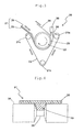
- FIG. 4 is a cross-sectional view schematically showing a combination of a conveyor belt with a guide and a pulley in the conventional art.
- the conveyor belt 31 with a guide is constituted of a flat belt 32, and a guide 33 projecting from a surface of the flat belt 32 on a side of a pulley 34 along a longitudinal direction.
- the conveyor belt 31 travels in the state in which the guide 33 is fitted into a guide groove 35 formed at the pulley 34, thereby preventing any meander of the conveyor belt 31.
- the guide 33 is frequently joined to the flat belt 32 via an adhesive agent or by thermal fusion. Therefore, there is an adhesion deficiency, a thermal fusion deficiency, or the exertion of a deviated load such as a torsion on the belt, thereby raising a problem that the guide 33 is unfavorably detached from the flat belt 32.
- the guide 33 is detached from the flat belt 32, unfavorably resulting in the unstable traveling of the belt 31 so as to degrade conveying performance.
- Patent literature 1 discloses a conveyor belt with a guide, in which a guide having a predetermined skin layer is bonded to a belt body via the skin layer. Patent literature 1 discloses that the guide cannot be readily detached from a belt body (a flat belt). However, in the case of insufficient adhesion or exertion of a deviated load such as a distortion on the belt, there is a fear that the guide may be accidentally detached from the flat belt. Patent literature 1: Japanese Unexamined Patent Publication No. 2003-12133
- An object of the present invention is to provide a conveyor belt with a guide having a high traveling stability and conveying performance for a long time.
- the inventors of the present invention made new findings that in a conveyor belt with a guide constituted of a flat belt and a guide, the guide cannot be detached from the flat belt when the flat belt and the guide are integrally molded with an elastic material, thus achieving a high traveling stability and conveying performance for a long time. Finally, they reached the completion of the present invention.
- a conveyor belt with a guide according to the present invention is featured by the following points:
- the flat belt and the guide being integrally molded with an elastic material.
- the guide cannot be detached from the flat belt, thus achieving a high traveling stability and conveying performance for a long time.
- FIG. 1 is a cutaway and perspective view showing a conveyor belt with a guide in one embodiment according to the present invention
- FIG. 2 is a cross-sectional view schematically showing the combination of the conveyor belt and a pulley.
- the conveyor belt 1 with a guide is constituted of a flat belt 2, and a guide 3 projecting from a surface of the flat belt 2 on a side of a pulley 10 along a longitudinal direction.
- the flat belt 2 and the guide 3 are integrally molded with an elastic material.
- the guide 3 is fitted to a guide groove 11 formed at the pulley 10. Since the conveyor belt 1 travels in this state, the guide 3 cannot be detached from the flat belt 2, so that the conveyor belt 1 can achieve a high traveling stability and conveying performance for a long time.
- the core wire 4 can be used various kinds of known materials which can be used as the core wire. Examples include a metallic wire, a polyester cord, a polyamide cord, a glass cord, and aramid or rayon which is formed into the shape of yarn or fiber.
- the number of core wires 4 is not particularly limited, but may be arbitrarily selected in accordance with a required conveying force.
- the core wires 4 arranged in the longitudinal direction of the conveyor belt 1 may be uniformly embedded across the width of the belt 1 or may be densely embedded at either the center thereof or both side edges inside of the flat belt 2.
- the shape of the core wire 4 is not particularly limited, but the core wire 4 may be sheet cloth or braded cloth made of the above-described aramid.
- the shape of the guide 3 is not particularly limited as long as the guide 3 has a function of a guide for preventing any meander of the belt 1, and therefore, examples of a cross-sectional shape of the guide 3 include a trapezoid, a rectangle, a semi-circle, V, U and the like. Furthermore, a vertical groove 5 is formed along the longitudinal direction of the belt 1 at the bottom of the guide 3. The vertical groove 5 can apply flexibility to the guide 3, and further, can reduce the material constituting the guide 3, thereby achieving cost reduction.
- the vertical groove 5 should be preferably formed into a shape such as a semi-circle, V or a rectangle.
- the single guide 3 projects from substantially a center surface of the flat belt 2 on a side of the pulley 10 along the longitudinal direction.
- the guide 3 may arbitrarily project from any position in the arbitrary number selected in accordance with the width of the flat belt or the pulley to be combined, and therefore, the position and the number are not particularly limited to those shown in FIGS. 1 and 2.
- a plurality of guides may project from the flat belt.
- at least one guide should preferably project from each of both ends of the flat belt.
- a plurality of guides may be disposed adjacently to each other at substantially a center of the flat belt.
- one kind or two or more kinds of elastic material can be selected among rubber, a synthetic resin and a thermoplastic elastomer.
- the rubber include natural rubber, isoprene rubber, butadiene rubber, styrene-butadiene rubber, ethylene propylene rubber, chloroprene rubber, chlorinated polyethylene rubber, epichlorohydrin rubber, nitrile rubber, acrylic rubber, polyurethane rubber, and an H-NBR (a hydrogenated nitrile-butadiene rubber).
- Examples of the synthetic resin include polyurethane, polyvinyl chloride, polycarbonate, polyester, polyalylate, a styrene-butadiene copolymer, a styrene-acrylonitrile copolymer, an acrylic copolymer, a styrene-acrylic acid copolymer, polyethylene, an ethylene-vinyl acetate copolymer, chlorinated polyethylene, polypropylene, a polyvinyl chloride-polyvinyl acetate copolymer, an alkyd resin, a polyamide resin, a polysulfone resin, a diallylphthalate resin, a ketone resin, a polyvinyl acetal resin, and a polyether resin.
- Examples of the thermoplastic elastomer include a polyester-based elastomer, a polyamide-based elastomer, and a polyolefin-based elastomer.
- the conveyor belt 1 should be particularly molded with one kind or two or more kinds selected from a group including polyurethane, polyvinyl chloride, a polyester-based elastomer, a polyamide-based elastomer, and a polyolefin-based elastomer.
- the conveyor belt 1 with the guide should be formed into an endless shape by joining both ends thereof to each other.
- the conveyor belt 1 can be stretched between the pulleys, to convey an object to be conveyed.
- the joint of both ends is not particularly limited, but it may be performed, for example, by thermal fusion or via an adhesive agent.
- FIG. 3 is a schematic view explanatory of a method for fabricating the conveyor belt with the guide in one example according to the present invention.
- an apparatus 20 for fabricating the conveyor belt with the guide is constituted of pulleys 21a, 21b and 21c, a guide molding pulley 22 interposed between the pulleys 21a and 21c, and a belt 23 stretched by the use of the pulleys 21a, 21b, 21c and 22.
- the belt 23 is brought into press-contact with the pulley 22 during non-operation of the apparatus by the effect of the pulley 21b: in contrast, during operation of the apparatus when a molten elastic material is poured between the pulley 22 and the belt 23, the elastic material is held between the pulley 22 and the belt 23, thereby keeping a predetermined clearance (a clearance equivalent to the thickness of the flat belt). Furthermore, a groove 29 having a shape in conformity with the guide in the conveyor belt with the guide is formed at substantially the center of the guide molding pulley 22 along the circumferential direction of the pulley 22.
- a molten elastic material 28 is continuously poured from an injection nozzle 30 while sequentially inserting a core wire 24 between the pulley 21a and the guide molding pulley 22.
- the elastic material 28 is coldly solidified during about half rotation of the pulley 22 by rotating the belt 23 and the pulley 22 in directions indicated by arrows.
- a conveyor belt 27 with a guide including a flat belt 25 having the core wire 24 embedded therein and a guide 26 is fabricated from between the pulley 21c and the pulley 22.
- the conveyor belt with the guide according to the present invention is not limited to the above-described fabricating method.
- a conveyor belt with a guide may be injection-molded or extruded into a predetermined shape, and thus, it may be fabricated by integrally molding the flat belt and the guide.
- the conveyor belt with the guide according to the present invention is used as a conveying apparatus in a printer or a copying machine, for conveying paper or the like (e.g., a printing sheet) while vertically holding it between two belts.
- the conveying apparatus using the conveyor belt with the guide according to the present invention is not limited to the above-described conveying apparatus, but it may be used as a conveying apparatus for conveying paper or the like (e.g., paper money) in a financial institution, a conveying apparatus for conveying a thin steel plate or a corrugated cardboard, or a conveying apparatus for use in precision equipment, food equipment, play equipment or a machine tool.
- the conveyor belt with the guide according to the present invention may be used as a driving belt.
Landscapes
- Engineering & Computer Science (AREA)
- Mechanical Engineering (AREA)
- Belt Conveyors (AREA)
Applications Claiming Priority (1)
| Application Number | Priority Date | Filing Date | Title |
|---|---|---|---|
| PCT/JP2005/002595 WO2006087800A1 (ja) | 2005-02-18 | 2005-02-18 | ガイド付搬送ベルト |
Publications (2)
| Publication Number | Publication Date |
|---|---|
| EP1849722A1 true EP1849722A1 (de) | 2007-10-31 |
| EP1849722A4 EP1849722A4 (de) | 2009-04-15 |
Family
ID=36916216
Family Applications (1)
| Application Number | Title | Priority Date | Filing Date |
|---|---|---|---|
| EP05710427A Withdrawn EP1849722A4 (de) | 2005-02-18 | 2005-02-18 | Förderband mit führung |
Country Status (6)
| Country | Link |
|---|---|
| US (1) | US20100059343A1 (de) |
| EP (1) | EP1849722A4 (de) |
| JP (1) | JPWO2006087800A1 (de) |
| CN (1) | CN101128372A (de) |
| CA (1) | CA2597522A1 (de) |
| WO (1) | WO2006087800A1 (de) |
Families Citing this family (6)
| Publication number | Priority date | Publication date | Assignee | Title |
|---|---|---|---|---|
| US7789221B2 (en) * | 2008-09-26 | 2010-09-07 | Laitram, L.L.C. | Living-hinge conveyor belt |
| WO2014020855A1 (ja) * | 2012-08-02 | 2014-02-06 | バンドー化学株式会社 | 伝動ベルト及びその製造方法 |
| PT2894115T (pt) * | 2014-01-10 | 2016-11-15 | Sandvik Intellectual Property | Correia transportadora e disposição de transportador provida de uma tal correia transportadora e método de produção de uma tal correia transportadora |
| DE102014218641A1 (de) * | 2014-09-17 | 2016-03-17 | Homag Holzbearbeitungssysteme Gmbh | Fördereinrichtung |
| CN112660741B (zh) * | 2020-11-23 | 2022-06-14 | 武汉大学 | 一种土压平衡盾构隧道防跑偏皮带传送机 |
| US20230211955A1 (en) * | 2022-01-03 | 2023-07-06 | Fenner, Inc. | D-shaped belt with flanges |
Citations (1)
| Publication number | Priority date | Publication date | Assignee | Title |
|---|---|---|---|---|
| DE10201343A1 (de) * | 2002-01-16 | 2003-07-31 | Contitech Antriebssysteme Gmbh | Aus Zahnriemen und Zahnscheibe bestehende Anordnung |
Family Cites Families (8)
| Publication number | Priority date | Publication date | Assignee | Title |
|---|---|---|---|---|
| JPH05139564A (ja) * | 1991-11-22 | 1993-06-08 | Tigers Polymer Corp | 搬送用薄肉ベルト |
| US5894918A (en) * | 1997-01-06 | 1999-04-20 | United Parcel Service Of America, Inc. | Conveyor having serpentine capabilities |
| JPH10324408A (ja) * | 1997-05-26 | 1998-12-08 | Mitsuboshi Belting Ltd | 紙幣搬送用歯付ベルトおよびその製造方法 |
| EP1063448A3 (de) * | 1999-06-22 | 2003-11-12 | NORDDEUTSCHE SEEKABELWERKE GMBH & CO. KG | Riemen, insbesondere Förderriemen und Verfahren zur Herstellung desselben |
| JP2002068438A (ja) * | 2000-08-23 | 2002-03-08 | Nitta Ind Corp | 搬送ベルト及びその製造方法 |
| US6626784B1 (en) * | 2001-11-28 | 2003-09-30 | The Gates Corporation | Low modulus belt |
| JP3921603B2 (ja) * | 2002-01-18 | 2007-05-30 | ニッタ株式会社 | エレベータ駆動用ベルト |
| US7789221B2 (en) * | 2008-09-26 | 2010-09-07 | Laitram, L.L.C. | Living-hinge conveyor belt |
-
2005
- 2005-02-18 JP JP2007503539A patent/JPWO2006087800A1/ja active Pending
- 2005-02-18 WO PCT/JP2005/002595 patent/WO2006087800A1/ja active Application Filing
- 2005-02-18 EP EP05710427A patent/EP1849722A4/de not_active Withdrawn
- 2005-02-18 CN CNA2005800477861A patent/CN101128372A/zh active Pending
- 2005-02-18 CA CA002597522A patent/CA2597522A1/en not_active Abandoned
- 2005-02-18 US US11/884,552 patent/US20100059343A1/en not_active Abandoned
Patent Citations (1)
| Publication number | Priority date | Publication date | Assignee | Title |
|---|---|---|---|---|
| DE10201343A1 (de) * | 2002-01-16 | 2003-07-31 | Contitech Antriebssysteme Gmbh | Aus Zahnriemen und Zahnscheibe bestehende Anordnung |
Non-Patent Citations (1)
| Title |
|---|
| See also references of WO2006087800A1 * |
Also Published As
| Publication number | Publication date |
|---|---|
| JPWO2006087800A1 (ja) | 2008-08-07 |
| CA2597522A1 (en) | 2006-08-24 |
| EP1849722A4 (de) | 2009-04-15 |
| US20100059343A1 (en) | 2010-03-11 |
| CN101128372A (zh) | 2008-02-20 |
| WO2006087800A1 (ja) | 2006-08-24 |
Similar Documents
| Publication | Publication Date | Title |
|---|---|---|
| EP1849722A1 (de) | Förderband mit führung | |
| JP5036829B2 (ja) | 繊維の搬送可撓菅を備える繊維貼付機械 | |
| EP1712813A2 (de) | Flachriemen | |
| JP2017045401A (ja) | シームレスベルト | |
| JP5895341B2 (ja) | コンベヤベルト | |
| KR20070121645A (ko) | 가이드 부착 반송 벨트 | |
| JP2007145555A (ja) | 記録媒体搬送ベルト及びこれを備えたインクジェット記録装置 | |
| KR20070070826A (ko) | 이송용 타이밍 벨트 및 이를 이용한 이송장치 | |
| WO2015111486A1 (ja) | 平ベルト | |
| JP6770901B2 (ja) | 搬送ベルトおよび搬送ベルトの製造方法 | |
| JP6062292B2 (ja) | 搬送ベルト | |
| JPS61263507A (ja) | 帯電防止搬送手段 | |
| JP2703791B2 (ja) | ベルト搬送装置 | |
| JP2834683B2 (ja) | 棧付ベルトの接合構造 | |
| KR102668451B1 (ko) | 디스플레이 제조용 무스크래치 타이밍 벨트 | |
| JP2008285312A (ja) | 平ベルト搬送装置 | |
| JP6895097B1 (ja) | スカートガード及びマンコンベヤ | |
| JP6739233B2 (ja) | コンベヤベルト | |
| JP2002356213A (ja) | 搬送用ベルトおよびコンベヤ装置 | |
| JP2011126235A (ja) | ベルト端部接合方法、無端ベルト製造方法、および無端平ベルト | |
| JP4344705B2 (ja) | 搬送装置および平ベルト | |
| JP4475451B2 (ja) | 紙葉類搬送用無端ベルト | |
| JPH0853213A (ja) | 搬送ベルト及び搬送装置 | |
| JP2006168844A (ja) | 搬送ベルト | |
| JPH10101208A (ja) | ベルト搬送装置及び搬送用ベルト |
Legal Events
| Date | Code | Title | Description |
|---|---|---|---|
| PUAI | Public reference made under article 153(3) epc to a published international application that has entered the european phase |
Free format text: ORIGINAL CODE: 0009012 |
|
| 17P | Request for examination filed |
Effective date: 20070802 |
|
| AK | Designated contracting states |
Kind code of ref document: A1 Designated state(s): CH DE FR GB IT LI NL |
|
| DAX | Request for extension of the european patent (deleted) | ||
| RBV | Designated contracting states (corrected) |
Designated state(s): CH DE FR GB IT LI NL |
|
| A4 | Supplementary search report drawn up and despatched |
Effective date: 20090317 |
|
| 17Q | First examination report despatched |
Effective date: 20090630 |
|
| STAA | Information on the status of an ep patent application or granted ep patent |
Free format text: STATUS: THE APPLICATION IS DEEMED TO BE WITHDRAWN |
|
| 18D | Application deemed to be withdrawn |
Effective date: 20091111 |