EP1845601A2 - Vorrichtung zur Kapazitätseinstellung und Verfahren für eine Sekundärbatterie - Google Patents
Vorrichtung zur Kapazitätseinstellung und Verfahren für eine Sekundärbatterie Download PDFInfo
- Publication number
- EP1845601A2 EP1845601A2 EP07007536A EP07007536A EP1845601A2 EP 1845601 A2 EP1845601 A2 EP 1845601A2 EP 07007536 A EP07007536 A EP 07007536A EP 07007536 A EP07007536 A EP 07007536A EP 1845601 A2 EP1845601 A2 EP 1845601A2
- Authority
- EP
- European Patent Office
- Prior art keywords
- secondary batteries
- capacity
- control board
- secondary battery
- capacity adjustment
- Prior art date
- Legal status (The legal status is an assumption and is not a legal conclusion. Google has not performed a legal analysis and makes no representation as to the accuracy of the status listed.)
- Granted
Links
Images




Classifications
-
- H—ELECTRICITY
- H02—GENERATION; CONVERSION OR DISTRIBUTION OF ELECTRIC POWER
- H02J—ELECTRIC POWER NETWORKS; CIRCUIT ARRANGEMENTS OR SYSTEMS FOR SUPPLYING OR DISTRIBUTING ELECTRIC POWER; SYSTEMS FOR STORING ELECTRIC ENERGY
- H02J7/00—Circuit arrangements for charging or discharging batteries or for supplying loads from batteries
- H02J7/50—Circuit arrangements for charging or discharging batteries or for supplying loads from batteries acting upon multiple batteries simultaneously or sequentially
- H02J7/52—Circuit arrangements for charging or discharging batteries or for supplying loads from batteries acting upon multiple batteries simultaneously or sequentially for charge balancing, e.g. equalisation of charge between batteries
- H02J7/54—Passive balancing, e.g. using resistors or parallel MOSFETs
Definitions
- the present Invention relates to apparatus and method for adjusting capacities of secondary batteries.
- lithium ion secondary battery in which lithium cobalt oxide is used for a positive pole and carbon is used for a negative pole and in a lithium secondary battery in which lithium secondary battery in a lithium secondary battery in which lithium cobalt oxide is used for the positive pole and a lithium metal is used for the negative pole
- these lithium ion secondary battery and lithium secondary battery are, in a general term, also called a lithium series secondary battery
- an organic solvent as ethylene carbonate is used for an electrolyte.
- a secondary battery capacity adjustment apparatus for an assembled cell unit, the assembled cell unit including: a plurality of secondary batteries; and a control board on which a capacity adjusting section is mounted, the capacity adjusting section being installed to correspond to each of the secondary batteries and configured to consume an electric power of a corresponding one of the secondary batteries to adjust a residual capacity of the corresponding one of the secondary batteries,
- the secondary battery capacity adjustment apparatus comprising: a priority order determining section configured to determine a priority order of the secondary batteries to be residual capacity adjusted in accordance with a mounted position of the capacity adjusting section corresponding to one of the secondary batteries to be residual capacity adjusted on the control board; and a secondary battery capacity adjusting section configured to have the electric power of each of the secondary batteries consumed by the corresponding capacity adjusting section in accordance with the determined priority order to adjust a residual capacity of each of the secondary batteries.
- a secondary battery capacity adjustment method for an assembled cell unit including: a plurality of secondary batteries; and a control board on which a capacity adjusting section is mounted, the capacity adjusting section being installed to correspond to each of the secondary batteries and configured to consume an electric power of a corresponding one of the secondary batteries to adjust a residual capacity of the corresponding one of the secondary batteries
- the secondary battery capacity adjustment method comprising: determining a priority order of the secondary batteries to be residual capacity adjusted in accordance with a mounted position of the capacity adjusting section corresponding to one of the secondary batteries on the control board; and having the electric power of each of the secondary batteries consumed by the corresponding capacity adjusting section in accordance with the determined priority order to adjust a residual capacity of each of the secondary batteries.
- a priority order of the secondary batteries to be residual capacity adjusted is determined in accordance with mounted positions of capacity adjusting sections on the control board, the capacity adjusting sections being heat generation sources.
- the mounted positions of the capacity adjusting sections has a meaning that, specifically, one or more of the capacity adjusting sections which are mounted at one or more positions difficult to exert a thermal influence on the other capacity adjusting sections have higher priority orders.
- the residual capacity adjustments can be executed without a local overheat of the control board.
- Fig. 1 is a schematic block diagram representing a preferred embodiment of a secondary battery capacity adjustment apparatus according to the present invention.
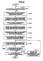
- Fig. 2 is a flowchart representing an operation of the secondary battery capacity adjustment apparatus in the preferred embodiment shown in Fig. 1.
- Fig. 3 is an explanatory view representing an example of a relationship between mounted positions of parts on a control board and priority orders of the secondary batteries to be capacity adjusted on the control board.
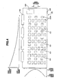
- Fig. 4 is an explanatory view representing another example of a relationship between mounted positions of parts and the priority order of the secondary batteries to be capacity adjusted on the control board.
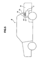
- Fig. 5 is a conceptual view representing an example of an assembled cell unit to which the secondary battery capacity adjustment apparatus and method according to the present invention is applicable mounted in a vehicle.
- Fig. 6 is a cross sectional view representing an example of the assembled cell unit to which the secondary battery capacity adjustment apparatus according to the present invention is applicable.
- Fig. 7 is a perspective view of the control board to which the secondary battery adjustment apparatus according to the present invention is applicable.
- Fig. 8 is a schematic block diagram of each of capacity adjustment sections shown in Fig. 1.
- Fig. 1 shows a schematic block diagram representing a preferred embodiment of a secondary battery capacity adjustment apparatus according to the present invention.
- Fig. 2 shows a flowchart representing an operation of the secondary battery capacity adjustment apparatus in the preferred embodiment shown in Fig. 1.
- Fig. 3 shows an explanatory view representing an example of a relationship between mounted positions of parts on a control board and priority orders of the secondary batteries to be capacity adjusted on the control board.
- Fig. 4 shows an explanatory view representing another example of a relationship between mounted positions of parts and the priority order of the secondary batteries to be capacity adjusted on the control board.
- Fig. 5 shows a conceptual view representing an example of an assembled cell unit to which the secondary battery capacity adjustment apparatus and method according to the present invention is applicable mounted in a vehicle.
- Fig. 1 shows a schematic block diagram representing a preferred embodiment of a secondary battery capacity adjustment apparatus according to the present invention.
- Fig. 2 shows a flowchart representing an operation of the secondary battery capacity adjustment apparatus in the preferred embodiment shown in Fig. 1.
- FIG. 6 shows a cross sectional view representing an example of the assembled cell unit to which the secondary battery capacity adjustment apparatus according to the present invention is applicable.
- Fig. 7 shows a perspective view of the control board to which the secondary battery adjustment apparatus according to the present invention is applicable.
- Fig. 8 shows a schematic block diagram of each of capacity adjustment sections shown in Fig. 1.
- An assembled cell unit 1 is mounted within a trunk room B1 of vehicle B as shown in Fig. 5.
- an opening B 3 is formed on a rear parcel panel B 2 of vehicle B to introduce cold air within assembled cell unit 1.
- Air within a passenger compartment is introduced into assembled cell unit 1 from opening B 3 via a duct 19.
- the mounted position of assembled cell unit 1 in the present invention is not limited to the example shown in Fig. 5 but assembled cell unit 1 may be mounted within the passenger compartment, a bottom part of a floor within the vehicle body, an engine compartment, and so forth.
- assembled cell unit 1 in the preferred embodiment is structured in the following way. That is to say, a plurality of sheet-type thin secondary batteries are stacked and whose positive terminals are connected to negative terminals sequentially in series with each other to form a cell pack 11. A plurality of cell packs 11 are stacked (in this example, four) and their positive terminals and negative terminals are connected in series with each other. Then, cell packs 11 thus stacked are aligned in plural (in the case of Fig. 6, three).
- a control board 15 to control respective secondary batteries 14 constituting the assembled cell unit 1 is attached onto upper end plate 12 and is housed within a casing 16 (secondary battery 14 itself is shown in Fig. 1).
- This control board is a printed circuit board on which electronic parts 151 such as integrated circuits to control respective secondary batteries 14 constituting the assembled cell unit 1 and resistors 152A (namely, capacity adjusting sections) to adjust respective capacities (residual capacities, namely, residual energies of the secondary batteries and, hereinafter, described merely as capacities) of corresponding secondary batteries are mounted.
- Fig. 7 shows an outline of control board 15.
- integrated circuits (IC chips) 151 to control respective secondary batteries 14 and resistors 152A electrically connected in parallel to respectively corresponding secondary batteries 14 to be capacity adjusted for respectively corresponding secondary batteries 14 are mounted in forms of matrices, respectively.
- Fig. 7 shows twelve integrated circuits 151 and twelve resistors 152A for convenience' sake.
- assembled cell unit 1 is, for example, constituted by 60 (sixty) sheet-type secondary batteries 14, 60 resistors 152A and 60 integrated circuits 151 are mounted on printed circuit board 153 to perform the capacity adjustments for the respective secondary batteries. This state is shown in Fig. 1.
- FIG. 3 and 4 show examples of mounting 21 (twenty one) integrated circuits 151, each integrated circuit 151 controlling two secondary batteries 14, 14 and 42 (forty two) resistors 152A, each resistor 152A performing the capacity adjustment of the corresponding one of 42 secondary batteries 14.
- a reference numeral 154 in Figs. 3 and 4 denotes each of connectors on which input and output terminals to perform communications with an external equipment and to connect between each thin secondary battery 14 and each resistor 152A and each integrated circuit 151
- a reference numeral 155 denotes an integrated circuit (IC chip) to perform an overall control of the assembled cell in the control printed circuit board (or printed circuit board) 153.
- Fig. 1, Fig. 3, and Fig. 7 do not mutually match the number of integrated circuits 151 and resistors 152A with one another. This is because according to the number of the secondary batteries, the numbers of the integrated circuits 151 and resistors 152A can variably be modified.
- a plurality of cell packs 11, 11, --- grasped with upper and lower end plates 12, 12 are housed in an assembled cell housing 17.
- An air intake port 171 through which air within a vehicle passenger compartment is introduced and an exhaust port 161 through which air introduced into assembled cell casing 17 is exhausted are formed in this assembled cell casing 17.
- a duct 19 on which a fan 18 is installed is coupled with intake port 171.
- An upper end of this duct 19 is connected to opening B 3 of rear parcel panel B 2 of vehicle B described above.
- Assembled cell unit 1 in this embodiment is constituted by a plurality of secondary batteries connected in series with each other, both ends thereof being connected with a vehicle load 2 such as a starter motor, a drive motor for an electric vehicle, or so forth.
- a vehicle load 2 such as a starter motor, a drive motor for an electric vehicle, or so forth.
- Each capacity adjustment section 152 includes: a resistor 152A connected in parallel to each of secondary batteries 14; a switching device 151C connected in series with this resistor 152A; and a capacity adjustment control section 1516 configured to control an on-and-off of this switching device 151C on the basis of a command issued from a control unit 155B and to transmit a voltage across the corresponding secondary battery 14 detected at voltage detection section 151.
- an isolation circuit 155A shown in Fig. 1 is an isolation transmission circuit to perform a transmission of signals between capacity adjustment control sections 151B of respective capacity adjustment sections 152 installed respectively on the plurality of secondary batteries 14 and control unit 155B, while electrically Isolating the signals using, for example, photo-couplers.
- Isolation circuit 155A is incorporated into an integrated circuit 155 shown in Figs. 3, 4, and 7.
- switching device 151C may be a switching device (or element) such as a transistor, a MOS-FET (Metal Oxide Semiconductor-Field Effect Transistor), or an IGBT (Insulated Gate Bipolar Transistor) or may be a mechanical switch such as a relay.
- switching device or element
- MOS-FET Metal Oxide Semiconductor-Field Effect Transistor
- IGBT Insulated Gate Bipolar Transistor
- a temperature sensor 3 to detect an actual temperature of a corresponding one of integrated circuits 151 mounted in plural on control board 15 is installed at an adjacent portion of integrated circuits 151 shown in Figs. 3, , 4, and 7, actual temperature Tr detected by means of the plurality of temperature sensors 3 being transmitted to control unit 155B.
- Temperature sensor 3 may be installed at a center X of a plurality of integrated circuits 151 shown in Fig. 7 or a plurality of sensors 3 may be installed at positions denoted by Y at predetermined intervals between integrated circuits 151. A grasping of actual temperature Tr during the adjustment of the capacity as will be described later becomes more accurate.
- a reference numeral 4 shown in Fig. 1 denotes a total voltage sensor to detect a whole voltage value of assembled cell unit 1 and a reference numeral 5 denotes a current sensor to detect a current flowing through whole assembled cell unit 1.
- a priority order of secondary batteries 14 to be capacity adjusted is determined in accordance with the mounted position of each of resistors 152A on control board 15.
- the priority order of one of secondary batteries 14 which corresponds to the position difficult to produce a thermal influence on other resistors 152A is set to be high. That is to say, the capacity adjustment is carried out in the following way. A current is caused to flow through corresponding resistor 152A from corresponding secondary battery 14 so that an electric power of corresponding secondary battery 14 is consumed by corresponding resistor 152A. Thus, the capacity of each corresponding secondary battery 14 is reduced to a target capacity. Thus, the capacity of each secondary battery 14 is adjusted.
- each of secondary batteries 14 (the secondary batteries connected in parallel to resistors 152A mounted at the four corners of control board 15) corresponding to resistors 152A mounted at four corners of control board 15 from among resistors 152A mounted in the matrix form has a highest priority order.
- the priority order of one of secondary batteries corresponding to resistor 152A located at an approximately center of control board 15 has a lowest priority order.
- Such a determination of the priority order according to the mounted position as described above is made for each layout of control board 15 and is stored in a memory of control unit 155B as an arrangement coefficient Kn of respective secondary batteries 14.
- capacity adjustment values of respective secondary batteries 14 have a correlation to heat generation quantities of resistors 152A.
- the priority of the capacity adjustment by making capacity adjustment quantity Vn of each of secondary batteries 14 multiplied by an arrangement coefficient Kn on which the mounted position is reflected is determined.
- a limit temperature is prescribed according to a grade of the corresponding electronic part.
- this limit temperature Tm is pre-stored in a memory of control unit 155B as 70°C.
- This limit temperature Tm indicates an unfavorable temperature when the corresponding electronic part is exposed to the limit temperature. In other words, a quality of the corresponding electronic part is guaranteed unless the temperature of the corresponding electronic part exceeds the limit temperature.
- the capacity adjustments for respective secondary batteries 14 are supposed to be executed to prevent temperatures of integrated circuits 151, 155 from exceeding limit temperature of 70°C due to a thermal influence from capacity adjustment sections (resistors) 152A.
- control unit 155B determines whether the present time is in a capacity adjustment mode at a step ST10.
- a timing of this capacity adjustment is not specifically limited but, for example, during an activation of the vehicle, during a vehicular stop, or so forth. Of course, it is possible to carry out the capacity adjustment during a vehicle traveling.
- control unit 155B Inputs voltages of respective secondary batteries 14 detected by means of respectively corresponding voltage detection sections 15 1A of respective secondary batteries 14 via respective capacity adjustment control sections 151B and calculates the capacity adjustment quantities required for respective secondary batteries 14 on the basis of the inputted voltage values. That is to say, it is generally known that a correlation between the voltage value of each of secondary batteries 14 and the capacity of the corresponding secondary battery 14 is present. Hence, on the basis of the voltage values, the respective capacity adjustment quantities are calculated.
- a method of calculation for the capacity adjustment quantities of respective secondary batteries 14 calculated herein is not specifically limited.
- the capacity adjustment values for respective secondary batteries 14 may be determined from a deviation between an average value of the voltage values of all secondary batteries 14 and a voltage value of one of secondary batteries 14 to be capacity adjusted or may be determined from the deviation using a maximum value of the voltage values of the plurality of secondary batteries 14 and a minimum value thereof as described in the Japanese Patent Application Publication No. 2003-284253 (published on October 3, 2003) described in the BACKGROUND OF THE INVENTION.
- control unit 155B determines a priority (order) by making each of capacity adjustment values Vn of secondary batteries 14 multiplied by a characteristic value of each of the mounted positions of corresponding resistors 152A on control board 15.
- control unit 155B detects actual temperature Tr of control board 15 by means of temperature sensor 3 at a step ST40. Since control unit 155B previously stores (pre-stores) a value of 70°C which is limit temperature Tm, control unit 155B calculates a difference between actual temperature Tr of control board 15 and limit temperature Tm at a step ST50.
- control unit 155B calculates a total sum of the capacity adjustment quantities at a step ST60 to calculate the total sum of the capacity adjustment quantities required for whole assembled cell unit 1. It should be noted that steps ST20 and ST30 and steps ST40, ST50, and ST60 can be executed in parallel with each other.
- the temperature difference between actual temperature Tr of control board 15 and limit temperature Tm corresponds to an amount of heat allowed in the capacity adjustment in terms of temperature.
- the total sum of the capacity adjustment quantities is a value of the amount of heat generated in the capacity adjustment in terms of electric power. If these dimensions are united, the capacity adjustment quantities that can be performed in the range of the temperature difference can be predicted. Specifically, if a capacity adjustment quantity required in a certain secondary battery 14 is W, this capacity adjustment quantity causes a current to flow through its capacity adjustment resistor 152A, its energy W can be consumed. The capacity of this certain secondary battery 14 can be reduced to a target voltage value. Since a resistance value of resistor 152A is known, a heat generation quantity by means of resistor 152A can be determined.
- control board 15 how degree of temperature of control board 15 is raised due to the heat generation from resistor 152A can previously be derived by a calculation or empirically. Hence, if the temperature difference between actual temperature Tr of control board 15 and limit temperature Tm is determined, which order and how many secondary batteries are simultaneously capacity adjusted within this temperature difference range can be determined.
- control unit 155B determines the number of secondary batteries 14 to simultaneously be capacity adjustable on the basis of temperature difference (Tm - Tr) and the total sum of the capacity adjustment quantities determined at the above-described steps.
- Tm - Tr temperature difference
- all secondary batteries 14 can simultaneously be capacity adjusted.
- Tm of control board 15 there is a possibility of exceeding limit temperature Tm of control board 15 if the capacity adjustments for all of secondary batteries 14 in assembled cell unit 1 are simultaneously executed.
- the capacity adjustment for each of selected secondary batteries 14 is started at a step ST80.
- This operation for each of the selected secondary batteries 14 is executed in such a way that a current is caused to flow through resistor 152A for a predetermined time by transmitting a capacity adjustment signal (viz., a command to drivingly turn on a switching device 151C) for the predetermined time to capacity adjustment control section 151B of corresponding capacity adjustment section 152 to turn on switching device 151C for the predetermined time from control unit 151.
- a capacity adjustment signal viz., a command to drivingly turn on a switching device 151C
- control unit 155B monitors whether there is one or more of secondary batteries 14 at which the capacity adjustments have been ended. If there is one of secondary batteries 14 at which the capacity adjustment is ended, the routine goes to a step ST100 at which control unit 155B determines whether the capacity adjustments for all secondary batteries 14 have been ended. If remaining one or more of secondary batteries 14 for which the capacity adjustments are not carried out (No) at step ST100, the routine goes to a step ST110 at which control unit 151 selects the subsequent order (priority order) secondary battery 14 and the routine returns to step ST80 at which the capacity adjustment for the corresponding one of the selected secondary batteries is started. Then, this routine of steps ST80 , ST90, ST100, and ST110 are repeated. After the end of the capacity adjustments for all secondary batteries 14, this processing is ended.
- the priority order of secondary batteries 14 to be capacity adjusted is determined in accordance with the mounted position of resistor 152A which is the heat generation source, a local high temperature generation portion can be prevented from occurring.
- the temperature over whole control board 15 is uniformly distributed. The capacity adjustment can efficiently be executed in a short time without overheat of control board 15.
- Fig. 6 shows another example of a relationship between mounted positions of parts 151, 152, and 155 on control board 15 according to the present invention and the priorities (priority order) of the secondary batteries to be capacity adjusted.
- the cooling wind from the passenger compartment of vehicle B is supposed to flow from a right direction in Fig. 4 to a left direction in Fig. 4.
- the priority order is determined only from the mounted positions of resistors 152A on control board 15 without consideration of flow of cooling wind from the passenger compartment of vehicle B.
- the priority order of one of secondary batteries 14 which corresponds to resistor 152A which is difficult to produce a thermal (heat) influence on the other resistors on the basis of the cooling wind from the passenger compartment and the mounted position of resistor 152A is set to be high.
- the priorities of secondary batteries 14 to be capacity adjusted which correspond to resistors 152A mounted at a downwind of the cooling wind, viz., at a left end position of control board 15 are set to be higher since the heat generated from these resistors is caused flow In the left direction in Fig. 4 and can be difficult to produce the thermal influence on other resistors 152A and the priorities of the secondary batteries which correspond to resistors 152A mounted at a right end position of control board 15 are set to be lower.
- the determination of the priorities in accordance with the mounted position and the flow of the cooling wind is made for each layout of control board 15 and is previously stored in a memory of control unit 155B as arrangement coefficients Kn of their respectively corresponding secondary batteries 14.
Landscapes
- Engineering & Computer Science (AREA)
- Power Engineering (AREA)
- Charge And Discharge Circuits For Batteries Or The Like (AREA)
- Secondary Cells (AREA)
- Electric Propulsion And Braking For Vehicles (AREA)
- Battery Mounting, Suspending (AREA)
Applications Claiming Priority (1)
| Application Number | Priority Date | Filing Date | Title |
|---|---|---|---|
| JP2006111896A JP5040154B2 (ja) | 2006-04-14 | 2006-04-14 | 二次電池の容量調整方法及び装置 |
Publications (3)
| Publication Number | Publication Date |
|---|---|
| EP1845601A2 true EP1845601A2 (de) | 2007-10-17 |
| EP1845601A3 EP1845601A3 (de) | 2008-12-03 |
| EP1845601B1 EP1845601B1 (de) | 2014-02-19 |
Family
ID=38421515
Family Applications (1)
| Application Number | Title | Priority Date | Filing Date |
|---|---|---|---|
| EP07007536.1A Ceased EP1845601B1 (de) | 2006-04-14 | 2007-04-12 | Vorrichtung zur Kapazitätseinstellung und Verfahren für eine Sekundärbatterie |
Country Status (4)
| Country | Link |
|---|---|
| US (1) | US7612534B2 (de) |
| EP (1) | EP1845601B1 (de) |
| JP (1) | JP5040154B2 (de) |
| CN (1) | CN101056001B (de) |
Families Citing this family (13)
| Publication number | Priority date | Publication date | Assignee | Title |
|---|---|---|---|---|
| JP4448111B2 (ja) * | 2006-07-31 | 2010-04-07 | 日立ビークルエナジー株式会社 | 電源システム |
| JP5254568B2 (ja) * | 2007-05-16 | 2013-08-07 | 日立ビークルエナジー株式会社 | セルコントローラ、電池モジュールおよび電源システム |
| US8076797B2 (en) * | 2008-05-15 | 2011-12-13 | Indy Power Systems Llc | Energy transfer circuit and method |
| JP5513138B2 (ja) * | 2009-01-28 | 2014-06-04 | 矢崎総業株式会社 | 基板 |
| US8981710B2 (en) | 2010-09-20 | 2015-03-17 | Indy Power Systems Llc | Energy management system |
| FR2972304A1 (fr) * | 2011-03-02 | 2012-09-07 | Commissariat Energie Atomique | Batterie avec gestion individuelle des cellules |
| KR101685461B1 (ko) * | 2011-09-05 | 2016-12-20 | 가부시키가이샤 니혼 마이크로닉스 | 시트상 이차전지의 평가장치 및 평가방법 |
| DE102011085787A1 (de) * | 2011-11-04 | 2013-05-08 | Sb Limotive Company Ltd. | Batteriemanagementeinheit mit einer Vielzahl von Überwachungs-IC Chips |
| US9812949B2 (en) | 2013-10-10 | 2017-11-07 | Indy Power Systems Llc | Poly-phase inverter with independent phase control |
| DE102014200096A1 (de) * | 2014-01-08 | 2015-07-09 | Robert Bosch Gmbh | Batteriemanagementsystem zum Überwachen und Regeln des Betriebs einer Batterie und Batteriesystem mit einem solchen Batteriemanagementsystem |
| JP6618236B2 (ja) * | 2014-02-24 | 2019-12-11 | 住友重機械工業株式会社 | 蓄電装置 |
| WO2019171662A1 (ja) | 2018-03-08 | 2019-09-12 | 三洋電機株式会社 | 管理装置、蓄電システム |
| CN113631842B (zh) * | 2019-03-15 | 2022-12-02 | 加特可株式会社 | 自动变速器的温度传感器诊断装置及诊断方法 |
Citations (2)
| Publication number | Priority date | Publication date | Assignee | Title |
|---|---|---|---|---|
| JP2003284253A (ja) | 2002-03-22 | 2003-10-03 | Shin Kobe Electric Mach Co Ltd | 二次電池の容量調整方式 |
| US20060043934A1 (en) | 2004-09-02 | 2006-03-02 | Nissan Motor Co., Ltd. | Cell set capacity controlling system and method |
Family Cites Families (8)
| Publication number | Priority date | Publication date | Assignee | Title |
|---|---|---|---|---|
| JP3217663B2 (ja) * | 1995-10-30 | 2001-10-09 | 株式会社岡村研究所 | 電力貯蔵装置 |
| EP0964497B1 (de) * | 1998-06-09 | 2010-10-13 | Makita Corporation | Batterieladegerät |
| JP2003004822A (ja) * | 2001-06-15 | 2003-01-08 | Matsushita Electric Ind Co Ltd | 電池電源装置 |
| JP3671901B2 (ja) * | 2001-11-21 | 2005-07-13 | 日産自動車株式会社 | 容量表示装置及び容量表示方法 |
| JP2003259549A (ja) * | 2002-02-28 | 2003-09-12 | Tokico Ltd | 車 両 |
| JP2004150951A (ja) * | 2002-10-30 | 2004-05-27 | Sanyo Electric Co Ltd | 電池管理回路、及び電子機器 |
| CN1567645A (zh) * | 2003-06-25 | 2005-01-19 | 黄耀俊 | 对电池组均衡充电的方法及系统 |
| JP4645514B2 (ja) * | 2006-04-14 | 2011-03-09 | 日産自動車株式会社 | 二次電池の容量調整方法及び装置 |
-
2006
- 2006-04-14 JP JP2006111896A patent/JP5040154B2/ja not_active Expired - Fee Related
-
2007
- 2007-04-12 EP EP07007536.1A patent/EP1845601B1/de not_active Ceased
- 2007-04-13 US US11/785,078 patent/US7612534B2/en active Active
- 2007-04-13 CN CN2007100960896A patent/CN101056001B/zh not_active Expired - Fee Related
Patent Citations (2)
| Publication number | Priority date | Publication date | Assignee | Title |
|---|---|---|---|---|
| JP2003284253A (ja) | 2002-03-22 | 2003-10-03 | Shin Kobe Electric Mach Co Ltd | 二次電池の容量調整方式 |
| US20060043934A1 (en) | 2004-09-02 | 2006-03-02 | Nissan Motor Co., Ltd. | Cell set capacity controlling system and method |
Also Published As
| Publication number | Publication date |
|---|---|
| JP2007287416A (ja) | 2007-11-01 |
| JP5040154B2 (ja) | 2012-10-03 |
| US20070247117A1 (en) | 2007-10-25 |
| EP1845601B1 (de) | 2014-02-19 |
| US7612534B2 (en) | 2009-11-03 |
| EP1845601A3 (de) | 2008-12-03 |
| CN101056001B (zh) | 2012-02-29 |
| CN101056001A (zh) | 2007-10-17 |
Similar Documents
| Publication | Publication Date | Title |
|---|---|---|
| EP1845601B1 (de) | Vorrichtung zur Kapazitätseinstellung und Verfahren für eine Sekundärbatterie | |
| US7612533B2 (en) | Capacity adjustment apparatus and method of secondary battery | |
| US7492129B2 (en) | Temperature abnormality detecting apparatus and method for secondary battery | |
| US7872452B2 (en) | Battery pack capacity adjusting device and method | |
| Stuart et al. | A modular battery management system for HEVs | |
| JP3503414B2 (ja) | 組電池の単電池間充電率調整装置 | |
| US7768235B2 (en) | Battery management system and method for automotive vehicle | |
| US7956580B2 (en) | Cell set capacity controlling system and method | |
| JP5874560B2 (ja) | 電池温度算出装置 | |
| EP2328256A2 (de) | Ausgleichsvorrichtung, Ausgleichsverarbeitungsprogramm, Batteriesystem, Elektrofahrzeug und Ausgleichsverarbeitungsverfahren | |
| CN100578852C (zh) | 电池组容量调节装置和方法 | |
| WO2008102228A1 (en) | Temperature adjustment mechanism and vehicle | |
| KR20190050637A (ko) | 배터리 관리 장치와 이를 포함하는 배터리 팩 및 자동차 | |
| US10170806B2 (en) | Battery cooling system | |
| KR20180032084A (ko) | 밸런싱 배터리를 이용한 배터리 관리 시스템 및 방법 | |
| JP3808367B2 (ja) | 二次電池の出力制御装置および方法、並びに電池パックシステム | |
| JP2007288886A (ja) | 二次電池の容量調整方法及び装置 | |
| JP3817863B2 (ja) | アルカリ系電池の充電装置 | |
| KR20220040601A (ko) | 전기 차량용 배터리의 절연 장치 | |
| KR20220025416A (ko) | 배터리 장치, 배터리 관리 시스템 및 배터리 셀 전압 보정 방법 | |
| JP4140413B2 (ja) | バッテリ冷却システムの異常検知装置および異常検知方法 | |
| US12555995B2 (en) | Vehicle impact detection device | |
| KR20220039226A (ko) | 전기 차량용 배터리의 난연 장치 | |
| KR20220023872A (ko) | 배터리 장치 및 출력 전력 제어 방법 | |
| CN107210613A (zh) | 本质安全的电池组电池的接通延迟 |
Legal Events
| Date | Code | Title | Description |
|---|---|---|---|
| PUAI | Public reference made under article 153(3) epc to a published international application that has entered the european phase |
Free format text: ORIGINAL CODE: 0009012 |
|
| 17P | Request for examination filed |
Effective date: 20070816 |
|
| AK | Designated contracting states |
Kind code of ref document: A2 Designated state(s): AT BE BG CH CY CZ DE DK EE ES FI FR GB GR HU IE IS IT LI LT LU LV MC MT NL PL PT RO SE SI SK TR |
|
| AX | Request for extension of the european patent |
Extension state: AL BA HR MK YU |
|
| PUAL | Search report despatched |
Free format text: ORIGINAL CODE: 0009013 |
|
| AK | Designated contracting states |
Kind code of ref document: A3 Designated state(s): AT BE BG CH CY CZ DE DK EE ES FI FR GB GR HU IE IS IT LI LT LU LV MC MT NL PL PT RO SE SI SK TR |
|
| AX | Request for extension of the european patent |
Extension state: AL BA HR MK RS |
|
| AKX | Designation fees paid |
Designated state(s): DE FR GB |
|
| GRAP | Despatch of communication of intention to grant a patent |
Free format text: ORIGINAL CODE: EPIDOSNIGR1 |
|
| INTG | Intention to grant announced |
Effective date: 20130829 |
|
| RIN1 | Information on inventor provided before grant (corrected) |
Inventor name: MIYAMOTO, TAKESHI Inventor name: MORITA, TSUYOSHI |
|
| GRAS | Grant fee paid |
Free format text: ORIGINAL CODE: EPIDOSNIGR3 |
|
| GRAA | (expected) grant |
Free format text: ORIGINAL CODE: 0009210 |
|
| AK | Designated contracting states |
Kind code of ref document: B1 Designated state(s): DE FR GB |
|
| REG | Reference to a national code |
Ref country code: GB Ref legal event code: FG4D |
|
| REG | Reference to a national code |
Ref country code: DE Ref legal event code: R096 Ref document number: 602007035134 Country of ref document: DE Effective date: 20140403 |
|
| REG | Reference to a national code |
Ref country code: DE Ref legal event code: R097 Ref document number: 602007035134 Country of ref document: DE |
|
| PLBE | No opposition filed within time limit |
Free format text: ORIGINAL CODE: 0009261 |
|
| STAA | Information on the status of an ep patent application or granted ep patent |
Free format text: STATUS: NO OPPOSITION FILED WITHIN TIME LIMIT |
|
| 26N | No opposition filed |
Effective date: 20141120 |
|
| REG | Reference to a national code |
Ref country code: DE Ref legal event code: R097 Ref document number: 602007035134 Country of ref document: DE Effective date: 20141120 |
|
| REG | Reference to a national code |
Ref country code: FR Ref legal event code: PLFP Year of fee payment: 10 |
|
| REG | Reference to a national code |
Ref country code: FR Ref legal event code: PLFP Year of fee payment: 11 |
|
| REG | Reference to a national code |
Ref country code: FR Ref legal event code: PLFP Year of fee payment: 12 |
|
| PGFP | Annual fee paid to national office [announced via postgrant information from national office to epo] |
Ref country code: GB Payment date: 20240320 Year of fee payment: 18 |
|
| PGFP | Annual fee paid to national office [announced via postgrant information from national office to epo] |
Ref country code: FR Payment date: 20240320 Year of fee payment: 18 |
|
| PGFP | Annual fee paid to national office [announced via postgrant information from national office to epo] |
Ref country code: DE Payment date: 20240320 Year of fee payment: 18 |
|
| REG | Reference to a national code |
Ref country code: DE Ref legal event code: R119 Ref document number: 602007035134 Country of ref document: DE |
|
| GBPC | Gb: european patent ceased through non-payment of renewal fee |
Effective date: 20250412 |
|
| PG25 | Lapsed in a contracting state [announced via postgrant information from national office to epo] |
Ref country code: DE Free format text: LAPSE BECAUSE OF NON-PAYMENT OF DUE FEES Effective date: 20251104 |
|
| PG25 | Lapsed in a contracting state [announced via postgrant information from national office to epo] |
Ref country code: GB Free format text: LAPSE BECAUSE OF NON-PAYMENT OF DUE FEES Effective date: 20250412 |
|
| PG25 | Lapsed in a contracting state [announced via postgrant information from national office to epo] |
Ref country code: FR Free format text: LAPSE BECAUSE OF NON-PAYMENT OF DUE FEES Effective date: 20250430 |