EP1842361B1 - Procede, programme d'ordinateur, ordinateur et systeme d'impression pour le piegeage de donnees image - Google Patents
Procede, programme d'ordinateur, ordinateur et systeme d'impression pour le piegeage de donnees image Download PDFInfo
- Publication number
- EP1842361B1 EP1842361B1 EP05825216A EP05825216A EP1842361B1 EP 1842361 B1 EP1842361 B1 EP 1842361B1 EP 05825216 A EP05825216 A EP 05825216A EP 05825216 A EP05825216 A EP 05825216A EP 1842361 B1 EP1842361 B1 EP 1842361B1
- Authority
- EP
- European Patent Office
- Prior art keywords
- image data
- image
- colour
- transformed
- objects
- Prior art date
- Legal status (The legal status is an assumption and is not a legal conclusion. Google has not performed a legal analysis and makes no representation as to the accuracy of the status listed.)
- Expired - Fee Related
Links
Images


Classifications
-
- H—ELECTRICITY
- H04—ELECTRIC COMMUNICATION TECHNIQUE
- H04N—PICTORIAL COMMUNICATION, e.g. TELEVISION
- H04N1/00—Scanning, transmission or reproduction of documents or the like, e.g. facsimile transmission; Details thereof
- H04N1/46—Colour picture communication systems
- H04N1/56—Processing of colour picture signals
- H04N1/58—Edge or detail enhancement; Noise or error suppression, e.g. colour misregistration correction
Definitions
- the invention relates to a method, a computer program, a computer and a printing system for trapping image data.
- Colored documents or document parts such as As images, color graphics or the like, are usually described by image data, which are divided into color separations.
- This type of data structure corresponds to many print output methods or apparatus that print the image data in color separations on a record carrier, e.g. in the colors yellow (Y), magenta (M), cyan (C) and black (K) or in black and one or more so-called highlight color colors or the Océ Custom Tone® colors.
- the Applicant develops and distributes corresponding digital electrographic printing systems. They are eg in the publication " The World of Printers, Technologies of Océ Printing Systems ", Dr. Gerd Goldmann (ed.), Océ Printing Systems GmbH, Poing, Ed. 7 (2002 ). Various offset and digital printing technologies are described on pages 249-286, pages 287-325 describe various digital color printing systems, and pages 233-248 describe the principles of color printing. On pages 209-232 fundamentals of digital image processing are described. On pages 246-248 Principles of Highlight Color Printing are described.
- Both digital printing and offset printing have the so-called passer problem. This is because printing on a sheet of paper can not be guaranteed due to mechanical tolerances, so that the positioning of the paper is always exactly the same for all printing operations.
- the problem occurs with monochrome printing, if the front and back are printed separately or if multicolored printing on one side.
- Front and backside printing interferes with this problem when e.g. a frame is printed around the front and back sides and these frames are not exactly on top of each other, which you notice when you hold the page against the light.
- the colors are offset relative to each other. As long as the different colors do not touch, this will not be noticeable. If the colors are in contact, the offset causes the colors on the contact line to be printed one above the other, which leads to a falsification of the color impression, or a white slit (flashback) remains at the contact line.
- Trapping is offered in different products on the market. It is e.g. Part of Raster Image Processors (RIPs) of the page description language (PDL) Adobe PostScript® Level 3, the software SuperTrap® offered by the company Heidelberger Druckmaschinen AG or the software TrapWise®, which is offered by the company Creo.
- RIPs Raster Image Processors
- PDL page description language
- Trapping can be done in two different ways. Trapping can be handled at the object level or at the bitmap level.
- the present invention relates in particular to the problem of trapping at the bitmap level from the point of view of performance, which are relevant in particular for high print volumes and complex originals for a smooth and efficient running of a printing process.
- the invention also relates to a trapping process for so-called highlight color images or abbreviated HLC images.
- Such images define colors in a color space specific to them, in which at least one color comprises a specific hue, which is usually apart from those of conventional dyes.
- This hue may e.g. be an application specific color (e.g., for a company logo in color) and / or adapted to allow access to color tones compatible with standard inks, e.g. yellow (Y), magenta (M), cyan (C) and black (K) can not be reached.
- Y yellow
- M magenta
- C cyan
- K black
- the applicant distributes e.g.
- a standard color and an HLC color can also be printed in different brightness levels or color saturation values.
- the standard color is black and printed in different shades of gray.
- Highlight color printing is more cost-effective than full-color printing with four basic colors (so-called four-color printing), in which the overprinting of the primary colors cyan, magenta, yellow and black different colors can be achieved.
- four-color printing it is disadvantageous that the luminosity of the colors that can be printed is limited despite the variety of colors. Particularly in the areas of red, green and blue, in the four-color printing process often a luminosity demanded by a customer and thus a customer-specific special ink can often not be achieved.
- Trapping increases the object belonging to one of the two colors involved by one or more pixels.
- one of the colors involved is lighter than the other. If you enlarge the object with the darker color, a definitely larger object is created, which can also be disturbing. If the object of the lighter color is enlarged, such an optical magnification does not occur because the object is covered by the darker color of the other object. For this reason, only the brighter objects are usually enlarged.
- FIG. 3 shows that the letters are lighter at the top and darker at the bottom than the background. In this case one would have the letters in the enlarge the upper area, while in the lower area the background would have to increase. Taking the letters as text (not as a bitmap) means that you need a new font in which all letters are only enlarged in the upper area.
- the changes of the first placed objects depend on later placed objects. This may require objects to be processed frequently.
- trapping objects can be defined that correspond to the enlargements of the contours of the objects, as in FIG. 5 shown.
- trapping not only means overcrowding but can also mean underfilling.
- large black areas are usually not only mapped to pure black, but also with a grid of another color such as cyan. Typically, this happens with color management. If white text is then printed on the black area, the cyan dots may protrude into the white area, so you have to reduce such a cyan grid (not the black area) at the edges. Since the CMM only responds to the profile in the printer and always fills the area with all specified colors according to the actual size, additional white contour objects must be inserted at the edges, which only affect the cyan plane and not the other planes. In particular, a trapping tool needs to know and evaluate the profiles used and generate corresponding new objects. Overall, trapping at the object level leads to a very complex processing and an unmanageable increase in the number of objects, some with new properties.
- Trapping is much easier at the bitmap level. If the objects are mapped successively to the background, you can immediately compare each edge pixel of the current object with the current background and thus decide easily, at which points the object and at which point the background is to be enlarged.
- the image data in an output image are provided pixel by pixel as color separation data, in particular as tarpaulin bitmaps and / or pointwise basic color data, and the image data are processed.
- objects with adjacent additional pixels are generated around pixels or pixels of different color separations of the output image according to an object specification, resulting in extended color separation data.
- the adjacent additional pixels of a color separation are then pixel-wise compared with the corresponding pixels of the output image and an additional pixel in dependence on the image data of the corresponding pixel of the output image made a decision whether corresponding color separation data of the output image pixel for generating a target pixel value is extended by a value corresponding to the additional pixel ,
- objects with adjacent additional pixels are generated around pixels of different color separations of the output image according to an object specification, thereby producing extended color separation data.
- the Adjacent additional pixels of a color separation are then compared pixel by pixel with the corresponding pixels of the output image and a decision is made at the coordinate of the adjacent additional pixel as a function of the data of the corresponding output image pixel, if the additional pixel is set in the present color separation.
- measures are provided with which highlight color data can be effectively trapped, in particular for data with one, two or three highlight color colors, which can occur in particular in combination with black.
- bitmaps it is possible, in particular, to perform a trapping on the basis of bitmaps.
- a preferred embodiment analyzes the bitmaps in such a way that contiguous areas can be determined and identified as image objects. Accordingly, while the invention employs incoming bitmap data, it may take action after recognition of the image objects known from object-based trapping techniques.
- color separations of the colors yellow (Y), magenta (M), cyan (C) and black (K) are initially provided and the image data of the colors yellow, magenta and cyan are converted into a color space of yellow (Y '), Magenta (M'), cyan (C '), red (R'), green (G ') and blue (B').
- objects with adjacent additional pixels are generated from the pixels of the color separations yellow, magenta and cyan, but not from the pixels of the color black.
- the following rules are used for the decision as to whether corresponding color separation data of the output image pixel for generating a target pixel value is extended by a value corresponding to the additional pixel:
- C"' M
- M''' K & M'' .
- G M
- K & G B ' K & B''' ,
- pixel-by-pixel intermediate image data can be determined from the image data of the output pixels and the additional pixels.
- C ' . M”" M"'
- M ' . Y”" Y"'
- Y ' . R”" R"'
- R ' . G G
- G . B”" B"'
- M""' M'"' R"" ⁇ B"" .
- Y""' Y'"' R"" ⁇ G ,
- the image data are preferably pixel-wise in binary form or in the form of bilevel or two-stage data, but may also be embodied pixel-by-pixel in more than two-stage or as multilevel data.
- the document trapping according to the invention is particularly computertechnical for a document page simple and therefore at least partially automatic to accomplish, if already the complete page is rasterized, in particular, if the trapping is carried out data-technically to bitmaps and thus the color separations, in particular the CMYK-plan are completely known; because then it can be relatively easily investigated for each point, whether an adjacent point is lighter or darker and colored according to the neighboring point or not.
- the trapping is thus carried out in particular to bitmaps, whereby, for example, the data processing speed is high.
- the invention can in particular be realized as a computer program which, when loaded and run on a computer, effects a method according to one of the preceding claims and / or as a computer on which such a computer program is loaded. Furthermore, the invention can be realized as a printing system with such a computer.
- the computer can be designed in particular as a raster image processor (raster image processor, RIP).
- trapping can basically be realized differently. It is important to distinguish whether to trap at the object or bitmap level.
- the trapping is done especially after ripping and separating and possibly also after the screening.
- the existing objects are rasterized completely by the ripping process, leaving only a single bitmap for a page. All overlaps are already taken into account so that only the final color transitions are visible on the bitmap.
- the trapping now has to take care of the complete bitmap, finding out color transitions without knowing the objects and changing the colors of the bitmap in the separated color separations in the vicinity of the color transitions according to the original colors. But the trapping can also regardless of ripping, separating or screening on bitmap objects of a PDL data stream that are integrated into the data stream, eg on screen shots, graphics or even photos with sharp color transitions.
- objects can also be bitmaps.
- Bitmaps are usually not handled when trapping objects, although trapping may be necessary here as well. For example, you can rip all used objects and then use the generated bitmap for the document instead of the objects. Such documents also require trapping. The procedure of not ripping such documents in principle from trapping is not always applicable, since sometimes one does not have access to the actual original (for example, when a bitmap comes from the Internet).
- Trapping objects allows editing depending on the type of an object.
- objects of the character type e.g. Objects of type surface or line.
- the number of examinations corresponds to the selection of 2 out of n objects, where n is the number of all objects on the page. This corresponds to a number of n * (n-1) / 2 investigations (quadratic effort with n). Especially with text, the number of characters are very large and are usually between 2000 and 4000. This corresponds to 2 to 8 million examinations.
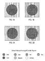
- FIG. 6A An example shows the in FIG. 6A illustrated flower. Although the flower consists of only 24 uniform leaves of the same color, each leaf is composed of 4 objects, namely two blue edges of different curvature and two yellow half centers. As a result, 98 objects must be considered, which corresponds to 4753 investigations. Doubling the number of leaves so already 19110 investigations must be carried out. Looking at not just a single flower, but a bouquet of four flowers, each overlapping the flowers ( FIG. 6B ), we obtain 76636 examinations for 24 leaves and 294528 examinations for 48 leaves. These examinations are also due when individual objects are completely covered and not visible.
- the 1000 flowers (98,000 leaves) can quickly become an additional 48 billion objects if you do not eliminate the hidden objects (which, however, adds extra effort). If one uses the method of changing the existing brighter objects, in this case no further objects are incurred.
- bitmap When examining a bitmap, the bitmap represents the result of mapping the objects and there is no overlapping of objects. The effort is thus initially independent of the number of objects.
- each pixel of the bitmap must be examined with each neighboring pixel.
- the number of pixels to be considered depends on the resolution of the bitmap. At 600 dpi that is about 34.8 million pixels, which corresponds to about 139.2 million examinations. Pixel research is usually much easier than examining objects. In particular, by utilizing the width of registers, the overhead of processing bitmaps can be significantly reduced.
- trapping bitmaps stored images are automatically included (suppression by specifying areas possible). Bitmaps occur in a few formats or, after ripping and separating, are present in the memory as a separate data stream. There is no dependence on the language. If one uses the trapping before the screening, usually four eight-bit-deep plan must be considered, which corresponds to a comparison of 32 bits.
- a pixel can have one of 4 billion color combinations of colors C, M, Y and K. If one uses the trapping after the screening, then one must differentiate whether it concerns a bilevel or multilevel printer. With a multilevel printer, only four four-bit-deep plans need to be considered. This means a cost reduction by a factor of two. Here, only trapping is possible depending on the brightness of the primary colors in the multilevel stages. A pixel can only have one of 64 K color combinations of the colors C, M, Y and K. For a bilevel printer, only four one-bit-deep schedules need to be considered. This means a cost reduction by a factor of eight.
- Bitmap trapping should have a constant overhead for a given depth of the planet at a given resolution (regardless of the number of objects and regardless of content, that is, color transitions).
- the input data in full-color data is in four one-bit-deep plans.
- HLC multiple highlight color
- the method can be used or extended analogously.
- both the pixel to be compared and the neighbor pixel can have one of 16 colors, ie, 256 color combinations. If the pixel is set in the black plane and in at least one other plane, the result will turn black, so that we can handle all these cases as well the value would be set only in the black plane. This halves the number of colors to 8, so that only 64 color combinations are to be checked.
- Step 1 Filter the pure primary colors
- the basic colors are the colors cyan, magenta, yellow, red, green and blue. At first, we do not consider black and white as the basic color.
- cyan these are all pixels for which one bit is set in the cyan plane but no bit is set in all other planes.
- magenta and yellow the same applies analogously.
- red these are all pixels for which one bit is set in the magenta plane and in the yellow plane, but no bit is set in all other planes.
- green and blue the same applies analogously.
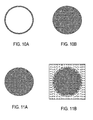
- a second step the contents of the plans of the first step are enlarged to objects with additional pixels.
- Contiguous objects of the plan can be enlarged by up to 24 pixels.
- Figs. 8A and 8B illustrate this.
- Step 3 Filter enlargement for darker colors that do not contain the current color
- C is the next darker base color, so lighter than G, M, R, B and K. C is considered as the current color, so that only M and K are eligible for the cut. Thus, M and K are thus decoded and C "cut to get C '".
- the brightnesses have to be sorted according to their color and their brightness level, where there can be overlaps in the brightness between different planes. For example, this could look like this for three brightness levels per pixel and plane: L K 0 > L Y 0 > L Y 1 > L Y 2 > L C 0 > L G 0 > L M 0 > L C 1 > L G 1 > L R 0 > L M 1 > L B 0 > ... > L K 2
- M is the next darker base color, ie lighter than R, B and K. M is not taken into account as the current color, so only K can be considered for the cut. Thus, K is cut with M "to get M '".
- B is the next darker base color, so only brighter than K. B as the current color is not taken into account, so that for the cut only K is eligible.
- C"' M
- M''' K & M'' .
- G M
- K & G . B ' K & B'''''
- Figs. 9A and 9B illustrate this step using the example of cyan.
- Step 4 Mix with pure original base color
- FIG. 10A and 10B illustrate this.
- steps 1 to 4 are performed, see also Figs. 19A to 19C ,
- FIG. 11A and 11B illustrate this.
- Fig. 12A shows original picture
- Fig. 12B the color separation for yellow
- Fig. 12C the color separation for cyan
- Fig. 12D the color separation for magenta.
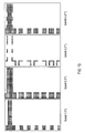
- Fig. 13 shows the individual steps described above for the yellow basic color.
- the image step 1 shows the pure yellow areas from the original
- image step 2 shows the enlarged areas
- image step 3 shows the section with the darker colors
- image step 4 shows the mixed pure yellow color.
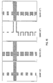
- Fig. 14 shows the individual steps for the cyan basic color.
- the image Step 1 shows the pure cyan areas from the original
- Image Step 2 shows the enlarged areas
- Image Step 3 shows the cut with the darker colors
- Image Step 4 shows the pure cyan color mixed to it.
- Fig. 15 shows the individual steps for the green basic color.
- the image step 1 shows the pure green areas from the original, image step 2 shows the enlarged areas, image step 3 shows the section with the darker colors and image step 4 shows the mixed pure green color.
- Fig. 16 shows the individual steps for the magenta basic color.
- the image step 1 shows the pure magenta areas from the original, image step 2 shows the enlarged areas, image step 3 shows the section with the darker colors and image step 4 shows the mixed pure magenta color.
- Fig. 17 shows the individual steps for the red basic color.
- the image step 1 shows the pure red areas from the original, image step 2 shows the enlarged areas, image step 3 shows the section with the darker colors and image step 4 shows the mixed pure red color.
- Fig. 18 shows the individual steps for the blue basic color.
- the image step 1 shows the pure blue areas from the original, image step 2 shows the enlarged areas, image step 3 shows the section with the darker colors and image step 4 shows the mixed pure blue color.
- Fig. 19A shows step 5 for the yellow color separation
- Fig. 19B shows step 5 for the cyan color separation
- Fig. 19C shows step 5 for the magenta color separation.
- HLC data highlight color data
- step 5 is not necessary here.
- the image data describes two colors, eg black K and a highlight color H, then the following can be done:
- step 4 the pure overlay is mixed with the original highlight color.
- H H
- HLC In contrast to the treatment of solid colors or corresponding data, in which the primary colors C, M, Y, K or R, G, B are fixed with their brightnesses, HLC can be colors of different or equal brightness, which from application to application, in particular from printing device to printing device are different. Therefore, in this case, the brightness of the HLC colors is determined and supplied to the trapping system from the outside, on the basis of which it decides which color is trapped to which other color. If both HLC colors have the same brightness (or deviate only slightly from one another in a predefined tolerance range), the colors are no longer trashed against each other, but only against black.
- steps 1-4 of the method are performed for both HLCs, respectively.
- step 4 the pure overlay is mixed with the original HLC.
- H ⁇ 2 ⁇ "'' H ⁇ 2 ⁇ "'
Abstract
Claims (25)
- Procédé de trapping de données d'image, dans lequel- les données d'image dans une image élémentaire se présentant sous la forme de données d'image élémentaire sont délivrées, quant aux points d'image, sous la forme de données de sélections chromatiques en couleurs élémentaires (Y, M, C), ledit procédé comportant les étapes suivantes :- dans une première étape, les données d'image élémentaire sont transformées en premières données d'image transformées (Y', M', C', R', G', B') de telle sorte que chaque point d'image élémentaire qui n'est pas que noir ou blanc est représenté en couleurs fondamentales, les couleurs fondamentales comportant les couleurs élémentaires (Y, M, C) et d'autres couleurs fondamentales (R, G, B) qui sont déterminées par des opérations logiques ET, OU et/ou NON à partir des couleurs élémentaires, et à chaque point d'image des premières données d'image transformées (Y', M', C', R', G', B') est associée au maximum une couleur fondamentale (Y, M, C, R, G, B),- dans une deuxième étape, les premières données d'image transformées (Y', M', C', R', G', B') sont transformées quant aux couleurs fondamentales en des deuxièmes données d'image transformées (Y" , M" , C" , R" , G" , B" ) de sorte que des objets contigus d'une couleur fondamentale sont agrandis conformément à une instruction d'agrandissement,- dans une troisième étape, les deuxièmes données d'image transformées (Y" , M" , C" , R", G", B" ) sont filtrées pour donner des troisièmes données d'image transformées (Y"', M"', C"', R"', G"', B"') de sorte que la donnée d'image d'une couleur fondamentale est transférée vers un point d'image seulement dans le cas où le point d'image contient également une couleur fondamentale plus sombre,- dans une quatrième étape, les troisièmes données d'image transformées (Y"', M"', C"', R"' G''', B"') sont transformées en des quatrièmes données d'image transformées (Y"" , M"", C"", R"'', G"", B"") de telle sorte qu'aux troisièmes données d'image transformées (Y"', M"', C"', R"', G"', B"') d'une couleur fondamentale sont ajoutées par mélange, quant aux points d'image, les premières données d'image transformées (Y', M', C', R', G', B') de la même couleur fondamentale.
- Procédé selon la revendication 1, dans lequel dans une cinquième étape les quatrièmes données d'image transformées (Y"" , M"", C"", R"", G"", B"") sont transformées, quant aux points d'image, en des données d'image cible des couleurs élémentaires (Y""', M""', C""') de sorte qu'aux quatrièmes données d'image transformées des couleurs élémentaires (Y"", M"", C"") sont ajoutées par mélange les quatrièmes données d'image transformées des autres couleurs fondamentales (R"", G"", B"").
- Procédé selon la revendication 1 ou 2, dans lequel dans la première étape des données d'image élémentaire des couleurs jaune, magenta, cyan et noir sont transformées en des premières données d'image transformées d'un espace chromatique comportant les couleurs jaune, magenta, cyan, rouge, vert et bleu.
- Procédé selon la revendication 3, dans lequel la première transformation est effectuée conformément aux règles


 - les grandes lettres C, Y, M, R, G et B désignent chacune une matrice des données d'image élémentaire de la sélection chromatique cyan, jaune, magenta, rouge, vert et bleu,- K désigne une matrice des points d'image de la sélection chromatique noir,- C', Y', M', R', G' et B' désignent les matrices, formées par la première étape, des premières données d'image transformées obtenues à partir des opérations de calcul correspondantes pour donner les sélections chromatiques et- l'opération « | » désigne une opération « OU », l'opération « & » désigne une opération « ET » et l'opération « ∼ » désigne l'opération Négation.
 - Procédé selon la revendication 4, dans lequel les données d'image sont traitées dans la deuxième étape en vue d'agrandir les objets conformément aux règles


où V désigne l'instruction pour générer les objets avec des points d'image élargis et C" , Y" , R" , G" et B" désignent des matrices pour les deuxièmes données d'image transformées obtenues par la deuxième étape et à partir des opérations de calcul correspondantes pour donner les sélections chromatiques. - Procédé selon la revendication 5, dans lequel les données d'image relatives aux points d'image d'une sélection chromatique sont mémorisées dans un fichier de points d'image et le fichier de points d'image est appliqué dans la troisième étape à un fichier d'application en vue de former des objets, tous les points d'image du fichier d'application qui se trouvent à une distance prédéterminée (d) de points d'image correspondants, étant placés.
- Procédé selon la revendication 6, dans lequel les points d'image dans le fichier de points d'image et dans le fichier d'application sont disposés en lignes et colonnes et un tableau est prévu qui contient des modèles de points d'image unidimensionnels, à chaque modèle de points d'image étant associé un modèle de points d'application correspondant, des groupes de points d'image d'une ligne du fichier de points d'image étant comparés aux modèles de points d'image dans l'application dans la direction des lignes, et le modèle de points d'application correspondant au modèle de points d'image qui coïncide étant introduit dans la ligne correspondante à la position correspondante dans le fichier d'application par une combinaison OU.
- Procédé selon la revendication 6 ou 7, dans lequel la distance (d) est modifiée automatiquement en fonction de la taille des caractères et/ou du tramage et/ou ou de la granularité.
- Procédé selon la revendication 5, dans lequel pour décider dans la troisième étape si une données de sélection chromatique correspondante du point d'image d'une image élémentaire est étendue d'une valeur correspondant au point d'image additionnel pour générer une valeur de point d'image cible, on utilise les règles suivantes :


où C"', Y"', M"', R"' et B"' représentent des matrices pour les troisièmes données d'image transformées obtenues par la troisième étape et à partir des opérations de calcul respectives donnant les sélections chromatiques. - Procédé selon la revendication 9, dans lequel on utilise dans la quatrième étape les règles suivantes :


où C"", Y"", M"", R"" et B"" représentent des matrices pour les quatrièmes données d'image transformées obtenues par la quatrième étape et à partir des opérations de calcul respectives donnant les sélections chromatiques. - Procédé selon la revendication 2, dans lequel on utilise dans la cinquième étape les règles suivantes :


où C""', Y""', M""', R""' et B""' représentent des matrices pour les cinquièmes données d'image transformées obtenues par la cinquième étape et à partir des opérations de calcul respectives donnant les sélections chromatiques. - Procédé selon l'une des revendications précédentes, dans lequel les données d'image ont, quant aux points d'image, deux niveaux.
- Procédé selon l'une des revendications 1 à 11, dans lequel les données d'image ont, quant aux points d'image, plus de deux niveaux.
- Procédé selon l'une des revendications précédentes, dans lequel le trapping est effectué en bitmap.
- Procédé selon l'une des revendications précédentes, dans lequel le trapping est effectué indépendamment d'une extraction, d'une séparation ou d'un screening au niveau d'objets bitmap d'un flux de données PDL qui sont intégrés dans le flux de données.
- Procédé selon la revendication 15, dans lequel le trapping est effectué au niveau d'une image capturée à l'écran, d'un graphique ou d'une photo.
- Procédé selon l'une des revendications 1, 6, 7, 8, 12, 13, 14, 15 ou 16, dans lequel les données d'image élémentaire ne contiennent que des données relatives à deux couleurs (H, K) et une autre sélection chromatique (H') est formée à partir des données des deux données de sélection chromatique (H, K), quant aux points d'image, conformément à l'instruction


la couleur la plus foncée est filtrée de l'autre sélection conformément à l'instruction
et la sélection ainsi générée est superposée aux données des sélections chromatiques d'origine conformément à l'instruction
les lettres H, K désignant chacune une matrice des données d'image élémentaire des sélections chromatiques des deux couleurs,
H', K' désignant les matrices, formées par la première étape, des premières données d'image transformées obtenues à partir des opérations de calcul respectives donnant les sélections chromatiques,
H", K" désignant les matrices, formées par la deuxième étape, des deuxièmes données d'image transformées obtenues à partir des opérations de calcul respectives donnant les sélections chromatiques,
H"', K"' désignant les matrices, formées par la troisième étape, des troisièmes données d'image transformées obtenues à partir des opérations de calcul respectives donnant les sélections chromatiques,
H"", K"" désignant les matrices, formées par la quatrième étape, des quatrièmes données d'image transformées obtenues à partir des opérations de calcul respectives donnant les sélections chromatiques,
V désignant l'instruction d'agrandissement. - Procédé selon l'une des revendications 1, 6, 7, 8, 12, 13, 14, 15 ou 16, dans lequel les données d'image élémentaire ne contiennent que des données relatives à deux couleurs Highlight Color (H1, H2) et au noir (K) et dans lequel différentes instructions de trapping sont utilisées en fonction de la différence de brillance entre les deux couleurs Highlight Color.
- Procédé selon la revendication 18, dans lequel, lorsque les brillances des deux couleurs Highlight Color sont sensiblement égales, on met en oeuvre un procédé selon la revendication 17.
- Procédé selon la revendication 19, dans lequel, lorsque les brillances des couleurs Highlight Color sont sensiblement différentes, les données de la couleur la plus sombre (H1) ne sont soumises au trapping que par rapport aux données de la couleur noire et les données de la couleur la plus claire sont soumises au trapping par rapport aux données des deux autres couleurs (H1, K).
- Procédé selon l'une des revendications précédentes, dans lequel on détermine ou on spécifie si des objets images en filigrane sont contenus dans les données d'image, et si une copie d'image est réalisée dans laquelle des objets images sont tout d'abord réduits conformément à une instruction (V) puis sont de nouveau agrandis de sorte que des objets images, dont les dimensions sont inférieures au moins dans une direction à une limite inférieure, sont éliminés au cours de la réduction de la sélection d'image avant d'appliquer les autres étapes du procédé de trapping.
- Procédé selon l'une des revendications précédentes, dans lequel des domaines contigus sont déterminés à partir des données d'image bitmap et sont classés comme objet puis on applique, quant à l'objet, des mesures de trapping.
- Programme informatique qui met en oeuvre un procédé selon l'une des revendications précédentes lors de son chargement et de son exécution sur un ordinateur.
- Ordinateur sur lequel est chargé un programme informatique selon la revendication 23.
- Système d'impression comportant un ordinateur selon la revendication 24.
Applications Claiming Priority (2)
| Application Number | Priority Date | Filing Date | Title |
|---|---|---|---|
| DE102004062841A DE102004062841A1 (de) | 2004-12-27 | 2004-12-27 | Verfahren, Computerprogramm, Computer und Drucksysteme zum Trapping von Bilddaten |
| PCT/EP2005/057147 WO2006069980A1 (fr) | 2004-12-27 | 2005-12-23 | Procede, programme d'ordinateur, ordinateur et systeme d'impression pour le piegeage de donnees image |
Publications (2)
| Publication Number | Publication Date |
|---|---|
| EP1842361A1 EP1842361A1 (fr) | 2007-10-10 |
| EP1842361B1 true EP1842361B1 (fr) | 2012-08-15 |
Family
ID=36084154
Family Applications (1)
| Application Number | Title | Priority Date | Filing Date |
|---|---|---|---|
| EP05825216A Expired - Fee Related EP1842361B1 (fr) | 2004-12-27 | 2005-12-23 | Procede, programme d'ordinateur, ordinateur et systeme d'impression pour le piegeage de donnees image |
Country Status (4)
| Country | Link |
|---|---|
| US (1) | US7856140B2 (fr) |
| EP (1) | EP1842361B1 (fr) |
| DE (1) | DE102004062841A1 (fr) |
| WO (1) | WO2006069980A1 (fr) |
Families Citing this family (8)
| Publication number | Priority date | Publication date | Assignee | Title |
|---|---|---|---|---|
| CN100576238C (zh) * | 2006-09-30 | 2009-12-30 | 北京大学 | 一种光栅图像处理方法和装置 |
| DE102006055626B4 (de) * | 2006-11-24 | 2008-12-04 | OCé PRINTING SYSTEMS GMBH | Verfahren, Computerprogramm und Drucksystem zum Trapping von Druckdaten mit einer Vielzahl von Objekten |
| DE102006055587B4 (de) * | 2006-11-24 | 2008-12-11 | OCé PRINTING SYSTEMS GMBH | Verfahren, Computerprogramm und Drucksystem zum Trapping von Druckdaten mit einer Vielzahl von Objekten |
| DE102006055625B4 (de) * | 2006-11-24 | 2008-12-04 | OCé PRINTING SYSTEMS GMBH | Verfahren, Computerprogramm und Drucksystem zum Trapping von Druckdaten mit einer Vielzahl von Objekten |
| DE102006055624B4 (de) * | 2006-11-24 | 2008-12-11 | OCé PRINTING SYSTEMS GMBH | Verfahren, Computerprogramm und Drucksystem zum Trapping von Druckdaten mit einer Vielzahl von Objekten |
| DE102008007339B4 (de) | 2008-02-04 | 2011-04-07 | OCé PRINTING SYSTEMS GMBH | Verfahren und Vorrichtung zum Erzeugen von Druckdaten |
| US8004718B2 (en) * | 2009-01-12 | 2011-08-23 | Xerox Corporation | Post RIP trapping |
| WO2017208108A1 (fr) * | 2016-05-30 | 2017-12-07 | Liefferink Hauke Maritz | Procédé d'impression d'images multi-couleurs |
Family Cites Families (15)
| Publication number | Priority date | Publication date | Assignee | Title |
|---|---|---|---|---|
| JPH01170169A (ja) | 1987-12-25 | 1989-07-05 | Dainippon Screen Mfg Co Ltd | 多色印刷のための画像図形修正処理方法 |
| US5131058A (en) * | 1990-08-24 | 1992-07-14 | Eastman Kodak Company | Method for obtaining output-adjusted color separations |
| JPH0817445B2 (ja) * | 1990-11-06 | 1996-02-21 | 大日本スクリーン製造株式会社 | 画像のカブセ処理方法 |
| US5613046A (en) * | 1993-03-31 | 1997-03-18 | Miles Inc. | Method and apparatus for correcting for plate misregistration in color printing |
| US5581667A (en) * | 1994-12-23 | 1996-12-03 | Xerox Corporation | Electronic trapping system for digitized text and images |
| CA2210552C (fr) * | 1996-09-27 | 2001-05-15 | Xerox Corporation | Systeme et methode d'attenuation de l'effet de halo visuel. |
| DE59702478D1 (de) | 1997-03-03 | 2000-11-16 | Oce Printing Systems Gmbh | Druck- und kopiergerät zum performance-angepassten, monochromen und/oder farbigen, ein- oder beidseitigen bedrucken eines aufzeichnungsträgers |
| US6236754B1 (en) * | 1998-01-08 | 2001-05-22 | Xerox Corporation | Image modification to reduce susceptibility to misregistration |
| JP4234281B2 (ja) * | 1998-10-22 | 2009-03-04 | ゼロックス コーポレイション | プリントシステム |
| JP2000196906A (ja) * | 1998-10-22 | 2000-07-14 | Xerox Corp | プリントシステム及び方法 |
| DE19912511A1 (de) * | 1999-03-19 | 2000-09-21 | Heidelberger Druckmasch Ag | Verfahren zur Erzeugung von Überfüllungskonturen in einer Druckseite |
| NL1012708C2 (nl) | 1999-07-26 | 2001-01-29 | Ocu Technologies B V | Afdrukken van digitale kleurenbeelden met locaal aangepaste halftoning. |
| US6509903B1 (en) * | 1999-10-06 | 2003-01-21 | Creoscitex Corporation Ltd. | System and method for recording an image |
| US6992798B2 (en) * | 2000-03-09 | 2006-01-31 | Agfa-Bevaert N.V. | Apparatus, product, and method of trapping using a distance buffer |
| DE10329339B4 (de) | 2003-06-30 | 2007-04-26 | OCé PRINTING SYSTEMS GMBH | Verfahren und Vorrichtung zum Aufbereiten einer Bildpunktdatei |
-
2004
- 2004-12-27 DE DE102004062841A patent/DE102004062841A1/de not_active Withdrawn
-
2005
- 2005-12-23 WO PCT/EP2005/057147 patent/WO2006069980A1/fr active Application Filing
- 2005-12-23 EP EP05825216A patent/EP1842361B1/fr not_active Expired - Fee Related
- 2005-12-23 US US11/719,156 patent/US7856140B2/en not_active Expired - Fee Related
Also Published As
| Publication number | Publication date |
|---|---|
| US7856140B2 (en) | 2010-12-21 |
| EP1842361A1 (fr) | 2007-10-10 |
| US20090141972A1 (en) | 2009-06-04 |
| WO2006069980A1 (fr) | 2006-07-06 |
| DE102004062841A1 (de) | 2006-07-13 |
Similar Documents
| Publication | Publication Date | Title |
|---|---|---|
| DE69910631T2 (de) | Bildanpassung um die Empfindlichkeit auf Falschregistrierung zu vermindern | |
| DE69935120T2 (de) | Automatische Verbesserung der Druckqualität basiert auf Grösse, Form, Orientierung und Farbe von Strukturen | |
| EP1842361B1 (fr) | Procede, programme d'ordinateur, ordinateur et systeme d'impression pour le piegeage de donnees image | |
| DE69822545T2 (de) | Bildverbesserung unter Benutzung einer Flächeninterpolation | |
| DE69826044T2 (de) | Vektorkartenplanarisierung und -einfang | |
| DE60035401T2 (de) | Gradientenbasierte Verbesserung von Farbtrennflächen mit Hilfe von gemusterten Bereichen | |
| DE10204751B4 (de) | Verfahren zur Konvertierung eines Linework Datenformats in das Format einer Seitenbeschreibungssprache | |
| EP1166548A1 (fr) | Procede de production de contours de remplissage par superposition dans une page a imprimer | |
| EP0764310A1 (fr) | Technique de production d'une matrice d'elements d'image en degrade continu | |
| EP2092730B1 (fr) | Procédé, programme informatique et système d'impression pour intercepter des données d'impression | |
| EP1002421B1 (fr) | Dispositif et procede permettant de preparer des documents destines a la reproduction polychrome | |
| DE102006055624B4 (de) | Verfahren, Computerprogramm und Drucksystem zum Trapping von Druckdaten mit einer Vielzahl von Objekten | |
| DE60033479T2 (de) | Bilderzeugungssystem und -verfahren | |
| DE69834227T2 (de) | Erkennung und Korrektion von Farblücken | |
| DE60306324T2 (de) | System und Verfahren zur Verarbeitung eines mehrfarbigen Bildes | |
| DE102006055625B4 (de) | Verfahren, Computerprogramm und Drucksystem zum Trapping von Druckdaten mit einer Vielzahl von Objekten | |
| DE102006047436B4 (de) | Verfahren und System zum automatischen Aufbereiten von Druckdaten für einen Druckvorgang | |
| EP0978097B1 (fr) | Procede pour modifier la dimension d'elements a traits | |
| DE10008286C1 (de) | Verfahren zum Drucken eines Bildes in zwei Farben | |
| DE102006055626B4 (de) | Verfahren, Computerprogramm und Drucksystem zum Trapping von Druckdaten mit einer Vielzahl von Objekten | |
| EP0970440A1 (fr) | Procede de traitement d'image et circuit pour modifier la resolution d'image | |
| DE102008007339B4 (de) | Verfahren und Vorrichtung zum Erzeugen von Druckdaten | |
| DE4402723A1 (de) | Verfahren zur Erzeugung von Halbtonvorlagen | |
| EP1223743B1 (fr) | Procédé de retouche copiante adaptative à la trame | |
| DE10305046B4 (de) | Verfahren zur Erzeugung eines Rasterbitmap Proofs |
Legal Events
| Date | Code | Title | Description |
|---|---|---|---|
| PUAI | Public reference made under article 153(3) epc to a published international application that has entered the european phase |
Free format text: ORIGINAL CODE: 0009012 |
|
| 17P | Request for examination filed |
Effective date: 20070727 |
|
| AK | Designated contracting states |
Kind code of ref document: A1 Designated state(s): DE FR GB |
|
| DAX | Request for extension of the european patent (deleted) | ||
| RBV | Designated contracting states (corrected) |
Designated state(s): DE FR GB |
|
| 17Q | First examination report despatched |
Effective date: 20080603 |
|
| GRAP | Despatch of communication of intention to grant a patent |
Free format text: ORIGINAL CODE: EPIDOSNIGR1 |
|
| GRAS | Grant fee paid |
Free format text: ORIGINAL CODE: EPIDOSNIGR3 |
|
| GRAA | (expected) grant |
Free format text: ORIGINAL CODE: 0009210 |
|
| AK | Designated contracting states |
Kind code of ref document: B1 Designated state(s): DE FR GB |
|
| REG | Reference to a national code |
Ref country code: GB Ref legal event code: FG4D Free format text: NOT ENGLISH |
|
| REG | Reference to a national code |
Ref country code: DE Ref legal event code: R096 Ref document number: 502005013020 Country of ref document: DE Effective date: 20121011 |
|
| PLBE | No opposition filed within time limit |
Free format text: ORIGINAL CODE: 0009261 |
|
| STAA | Information on the status of an ep patent application or granted ep patent |
Free format text: STATUS: NO OPPOSITION FILED WITHIN TIME LIMIT |
|
| 26N | No opposition filed |
Effective date: 20130516 |
|
| REG | Reference to a national code |
Ref country code: DE Ref legal event code: R082 Ref document number: 502005013020 Country of ref document: DE Representative=s name: PATENTANWAELTE SCHAUMBURG, THOENES, THURN, LAN, DE |
|
| GBPC | Gb: european patent ceased through non-payment of renewal fee |
Effective date: 20121223 |
|
| REG | Reference to a national code |
Ref country code: DE Ref legal event code: R097 Ref document number: 502005013020 Country of ref document: DE Effective date: 20130516 |
|
| REG | Reference to a national code |
Ref country code: FR Ref legal event code: ST Effective date: 20130830 |
|
| REG | Reference to a national code |
Ref country code: DE Ref legal event code: R081 Ref document number: 502005013020 Country of ref document: DE Owner name: OCE PRINTING SYSTEMS GMBH & CO. KG, DE Free format text: FORMER OWNER: OCE PRINTING SYSTEMS GMBH, 85586 POING, DE Effective date: 20130819 Ref country code: DE Ref legal event code: R082 Ref document number: 502005013020 Country of ref document: DE Representative=s name: PATENTANWAELTE SCHAUMBURG, THOENES, THURN, LAN, DE Effective date: 20130819 Ref country code: DE Ref legal event code: R081 Ref document number: 502005013020 Country of ref document: DE Owner name: OCE PRINTING SYSTEMS GMBH & CO. KG, DE Free format text: FORMER OWNER: OCE PRINTING SYSTEMS GMBH, 85586 POING, DE Effective date: 20120816 Ref country code: DE Ref legal event code: R082 Ref document number: 502005013020 Country of ref document: DE Representative=s name: SCHAUMBURG UND PARTNER PATENTANWAELTE MBB, DE Effective date: 20130819 Ref country code: DE Ref legal event code: R082 Ref document number: 502005013020 Country of ref document: DE Representative=s name: SCHAUMBURG & PARTNER PATENTANWAELTE GBR, DE Effective date: 20130819 Ref country code: DE Ref legal event code: R082 Ref document number: 502005013020 Country of ref document: DE Representative=s name: SCHAUMBURG & PARTNER PATENTANWAELTE MBB, DE Effective date: 20130819 |
|
| PG25 | Lapsed in a contracting state [announced via postgrant information from national office to epo] |
Ref country code: GB Free format text: LAPSE BECAUSE OF NON-PAYMENT OF DUE FEES Effective date: 20121223 Ref country code: FR Free format text: LAPSE BECAUSE OF NON-PAYMENT OF DUE FEES Effective date: 20130102 |
|
| REG | Reference to a national code |
Ref country code: DE Ref legal event code: R082 Ref document number: 502005013020 Country of ref document: DE Representative=s name: SCHAUMBURG UND PARTNER PATENTANWAELTE MBB, DE Ref country code: DE Ref legal event code: R082 Ref document number: 502005013020 Country of ref document: DE Representative=s name: SCHAUMBURG & PARTNER PATENTANWAELTE GBR, DE Ref country code: DE Ref legal event code: R082 Ref document number: 502005013020 Country of ref document: DE Representative=s name: SCHAUMBURG & PARTNER PATENTANWAELTE MBB, DE |
|
| PGFP | Annual fee paid to national office [announced via postgrant information from national office to epo] |
Ref country code: DE Payment date: 20201223 Year of fee payment: 16 |
|
| REG | Reference to a national code |
Ref country code: DE Ref legal event code: R119 Ref document number: 502005013020 Country of ref document: DE |
|
| PG25 | Lapsed in a contracting state [announced via postgrant information from national office to epo] |
Ref country code: DE Free format text: LAPSE BECAUSE OF NON-PAYMENT OF DUE FEES Effective date: 20220701 |