EP2092730B1 - Procédé, programme informatique et système d'impression pour intercepter des données d'impression - Google Patents
Procédé, programme informatique et système d'impression pour intercepter des données d'impression Download PDFInfo
- Publication number
- EP2092730B1 EP2092730B1 EP07822815.2A EP07822815A EP2092730B1 EP 2092730 B1 EP2092730 B1 EP 2092730B1 EP 07822815 A EP07822815 A EP 07822815A EP 2092730 B1 EP2092730 B1 EP 2092730B1
- Authority
- EP
- European Patent Office
- Prior art keywords
- trapping
- print data
- objects
- data
- printing
- Prior art date
- Legal status (The legal status is an assumption and is not a legal conclusion. Google has not performed a legal analysis and makes no representation as to the accuracy of the status listed.)
- Active
Links
- 230000005532 trapping Effects 0.000 title claims description 226
- 238000000034 method Methods 0.000 title claims description 107
- 238000004590 computer program Methods 0.000 title description 9
- 238000007639 printing Methods 0.000 claims description 114
- 238000000926 separation method Methods 0.000 claims description 9
- 238000001926 trapping method Methods 0.000 claims description 7
- 230000000694 effects Effects 0.000 claims description 4
- 238000003780 insertion Methods 0.000 claims description 4
- 230000037431 insertion Effects 0.000 claims description 4
- 239000003086 colorant Substances 0.000 description 78
- 230000008569 process Effects 0.000 description 40
- 238000012545 processing Methods 0.000 description 24
- 230000007935 neutral effect Effects 0.000 description 18
- 238000004080 punching Methods 0.000 description 6
- 239000013598 vector Substances 0.000 description 6
- 238000004364 calculation method Methods 0.000 description 5
- 238000004519 manufacturing process Methods 0.000 description 5
- 238000007645 offset printing Methods 0.000 description 5
- 230000006870 function Effects 0.000 description 4
- 230000007704 transition Effects 0.000 description 4
- 238000005516 engineering process Methods 0.000 description 3
- 241000287107 Passer Species 0.000 description 2
- 230000002411 adverse Effects 0.000 description 2
- 230000008901 benefit Effects 0.000 description 2
- 230000008859 change Effects 0.000 description 2
- 238000006243 chemical reaction Methods 0.000 description 2
- 239000003795 chemical substances by application Substances 0.000 description 2
- 210000001520 comb Anatomy 0.000 description 2
- 238000011161 development Methods 0.000 description 2
- 230000018109 developmental process Effects 0.000 description 2
- 238000010586 diagram Methods 0.000 description 2
- 238000012805 post-processing Methods 0.000 description 2
- 238000009877 rendering Methods 0.000 description 2
- 238000012216 screening Methods 0.000 description 2
- 238000004458 analytical method Methods 0.000 description 1
- 238000003491 array Methods 0.000 description 1
- 238000007630 basic procedure Methods 0.000 description 1
- 238000004891 communication Methods 0.000 description 1
- 238000005520 cutting process Methods 0.000 description 1
- 239000000975 dye Substances 0.000 description 1
- PCHJSUWPFVWCPO-UHFFFAOYSA-N gold Chemical compound [Au] PCHJSUWPFVWCPO-UHFFFAOYSA-N 0.000 description 1
- 229910052737 gold Inorganic materials 0.000 description 1
- 239000010931 gold Substances 0.000 description 1
- 239000000976 ink Substances 0.000 description 1
- 230000002452 interceptive effect Effects 0.000 description 1
- 239000004922 lacquer Substances 0.000 description 1
- 239000000203 mixture Substances 0.000 description 1
- 239000002245 particle Substances 0.000 description 1
- 238000007781 pre-processing Methods 0.000 description 1
- 229910052709 silver Inorganic materials 0.000 description 1
- 239000004332 silver Substances 0.000 description 1
- 230000001502 supplementing effect Effects 0.000 description 1
- 238000012360 testing method Methods 0.000 description 1
- 238000011144 upstream manufacturing Methods 0.000 description 1
Images


Classifications
-
- H—ELECTRICITY
- H04—ELECTRIC COMMUNICATION TECHNIQUE
- H04N—PICTORIAL COMMUNICATION, e.g. TELEVISION
- H04N1/00—Scanning, transmission or reproduction of documents or the like, e.g. facsimile transmission; Details thereof
- H04N1/46—Colour picture communication systems
- H04N1/56—Processing of colour picture signals
- H04N1/58—Edge or detail enhancement; Noise or error suppression, e.g. colour misregistration correction
-
- G—PHYSICS
- G06—COMPUTING; CALCULATING OR COUNTING
- G06K—GRAPHICAL DATA READING; PRESENTATION OF DATA; RECORD CARRIERS; HANDLING RECORD CARRIERS
- G06K15/00—Arrangements for producing a permanent visual presentation of the output data, e.g. computer output printers
- G06K15/02—Arrangements for producing a permanent visual presentation of the output data, e.g. computer output printers using printers
- G06K15/18—Conditioning data for presenting it to the physical printing elements
- G06K15/1801—Input data handling means
- G06K15/1825—Adapting the print data to an output condition, e.g. object trapping
- G06K15/1826—Object trapping
Definitions
- the invention relates to a method, a computer program and a printing system for trapping print data.
- the invention is related to other inventions disclosed in the German patent applications DE 10 2006 055 587.2 .
- DE 10 2006 055 625.9 and DE 10 2006 055 626.7 are described.
- Colored documents or document parts are usually described by image data, which are divided into color separations.
- This type of data structure corresponds to many print output methods or apparatus that print the image data in color separations on a record carrier, e.g. in the colors yellow (Y), magenta (M), cyan (C) and black (K) or in black and one or more so-called highlight color colors or the Océ Custom Tone® colors.
- the Applicant develops and distributes corresponding digital electrographic printing systems. They are eg in the Publication "The World of Printers, Technologies of Océ Printing Systems” Gerd Goldmann (ed.), Océ Printing Systems GmbH, Poing, Ed. 7 (2002). On pages 249-286 various offset and digital printing technologies are described Pages 287-325 various digital color printing systems are described and on Pages 233-248 are described basics of color printing. On Pages 209-232 are the basics of digital image processing described. On the Pages 246-248 Principles of Highlight Color Printing are described.
- Both digital printing and offset printing have the so-called passer problem. This is because printing on a sheet of paper can not be guaranteed due to mechanical tolerances, so that the positioning of the paper is always exactly the same for all printing operations.
- the problem occurs with monochrome printing when the front and back are printed separately or when multicolored printing on one side.
- Front and backside printing interferes with this problem when e.g. a frame is printed around the front and back sides and these frames are not exactly on top of each other, which you notice when you hold the page against the light.
- the colors are offset relative to each other. As long as the different colors do not touch, this does not stand out. If the colors touch each other, the offset causes the colors on the contact line to be printed on top of each other, resulting in a Falsification of the color impression leads, or it remains a white gap (speed camera) at the contact line.
- Trapping is offered in different products on the market. It is for example part of Raster Image Processors (RIPs) of the page description language (PDL) Adobe PostScript ® Level 3, the software SuperTrap ® offered by the company Heidelberger Druckmaschinen AG or the software TrapWise ® offered by the company Creo becomes.
- RIPs Raster Image Processors
- PDL page description language
- Creo the software SuperTrap ® offered by the company Heidelberger Druckmaschinen AG
- Creo the software SuperTrap ® offered by the company Creo becomes.
- Trapping can be done in two different ways. Trapping can be handled at the object level or at the bitmap level.
- edge lists are made of the objects, and objects that do not conform to a predetermined shape can be divided into corresponding standard shapes.
- the edge lists thus store information of the objects before they be rasterized. Trapping itself takes place on a bitmap level, whereby the additional information of the objects, eg in the form of edge lists, is taken into account.
- the drawback of trapping at the bitmap level that information about the objects is no longer present, is somewhat reduced with this method.
- the creation of these edge lists on the one hand consuming and moreover, several objects are created from individual objects, which makes the processing difficult again. Furthermore, the objects created in this way are no longer identical to the original objects. Objects with complex shapes can not be processed with this method or only to a very limited extent.
- the print data is first analyzed and trapping instructions are generated before being fed to a raster image processor (RIP).
- the trapping instructions indicate whether the print data includes text or graphics and whether they should be trapped in the RIP using a Shape Directory.
- the shape dictionary is generated during the analysis of the print data and transmitted to the RIP.
- the shape dictionary is a list of the shapes of the objects.
- the trapping areas or traps are generated during rastering in the RIP.
- This known method corresponds to that of US 2003/017934 A1 known method, wherein the shape dictionary corresponds to the edge list.
- object-level trapping in real time in a digital press is impractical because a user can not interactively trap the multitude of different rules, and object-level trapping generates such large-volume files that can not be processed in real time are.
- High-performance electrophotographic printing systems are often part of digital production printing environments in which the pre-processing and post-processing of printed media is automatically controlled.
- the document data is conveyed in such production printing environments in the form of document data streams between the individual workstations.
- print data streams and printing systems that are suitable for processing a wide variety of print data streams, including AFP and IPDS, are described in the publication already mentioned " The World of Printers, "Dr. Gerd Goldmann (Editor), Océ Printing Systems GmbH, 7th Edition (Nov. 2002), ISBN 3-00-001019-X., In Chapter 14 (pages 343-361 ) is described, for example, the print server system Océ PRISMAproduction.
- this flexible print data server system is capable of printing data from data sources such as a source computer, print data in a particular print data language such as AFP (Advanced Function Presentation), MO: DCA, Printer Command Language (PCL), PostScript, SPDS (Siemens Print Data Stream), in the Portable Document developed by Adobe Systems Inc.
- PDF PDF
- LCDS Line Coded Document Data Stream
- IPDS Intelligent Printer Data Stream
- Another way to store additional control data in an AFP data stream is to store data in so-called object containers, see eg in the Publication No. SC31-6802-05, pages 93-95 ,
- IPDS TM Intelligent Printer Data Stream TM
- IPDS and AFP data streams typically contain and / or reference so-called resources that contain data needed to output the documents.
- the data of a resource can be used multiple times for one or more print jobs, which in turn contain multiple documents or document parts, by simple referencing, without having to be repeatedly transmitted.
- a subsequent processing unit eg. a print server or a printing device
- the amount of data to be transferred from one processing unit eg, a document-generating host computer
- a subsequent processing unit eg, a print server or a printing device
- Examples of such resources are fonts or overlays with documents.
- the resources can be contained in the print data stream itself or can be transmitted separately from it between the systems involved and can only be referenced within different documents. It can be provided in particular that the resources in the processing device (eg print server or printing device) are already stored so that they do not need to be re-transmitted with each print job, but only need to be referenced.
- resources that are in different locations in the AFP document data stream come from different sources, with the corresponding variable data of the documents, e.g. database-derived data for invoices, e.g. Billing addressee, invoice number, invoice amount etc. merged.
- the resource data can be integrated as internal resources in the document data stream or called as external resources via a resource name from libraries. In a parsing process, the data is checked for consistency.
- the invention has for its object to provide a method, a computer program and a system for trapping print data, wherein the trapping is largely automatically executable.
- the trapping can be carried out in particular in an electronic, digital high-performance printing system.
- the advantage can be achieved that, without the production of additional tables or lists about the shape of the objects, the complete information of the objects is available for the calculation of the overfills. Since then the traps in the pixel file are created either when punching out or when rasterizing, it is not necessary to create additional object-level objects for the trapping. The determination of the trapping on the basis of the individual objects with respect to the pixel file and the insertion of the traps in the pixel file can thus be carried out without delay of the printing process in the printing data controller of the printing device.
- Conversion of individual objects does not necessarily mean that only a single object can be transferred at a given time. It is also possible that several objects are transferred in parallel from the print data to the pixel file. Rather, individual means that the objects being transferred do not overlap locally in the image with other objects that are transferred at the same time, thus considerably complicating the calculation of trappings.
- the traps are created both in punching by reducing the area for the objects to be inserted and in rasterizing by expanding the objects with traps.
- trapping can be performed in a print server and / or printer without delaying the printing process. It is thus possible to trap a print data stream "on the fly".
- the inventive method is performed in real time in a pressure data controller of a printing device.
- a method of trapping print data having a plurality of objects wherein traps are detected only at edges of each of the objects when the brightness of the respective object to the adjacent area differs by a difference amount that is greater than the predetermined threshold.
- This method is preferably developed in such a way that overcrowding is always determined for an object with highlight color color, even if the adjacent object should have a similar brightness, since with an incorrect registration of an object consisting of highlight color color always the so-called "speed camera "arise, the narrow white gaps between adjacent objects that should be avoided.
- a third aspect of the present invention which may be used alone or in conjunction with the foregoing aspects, traps in the region of a narrow, long tip that approximately form a corresponding tip do not exceed a predetermined width of trapping in the X direction and extends in the Y-direction with respect to the outermost point of the tip of the non-trapped object.
- the trapping can be easily cut off when a certain distance to the tip is reached. This method can be carried out with the least amount of computation. As a result, the execution of the method according to the invention in real time and without complex computing facilities is facilitated.
- a method of trapping print data having a plurality of objects is provided.
- the print data is generated along with trapping instructions in a print data stream for trapping, transmitted to a print data processing device and / or processed in the print data processing device, the print data stream referencing resource data containing trapping parameters and / or trapping instructions.
- the print data stream may in particular be sent to a print data processing device, e.g. be transferred to a printing device.
- the trapping parameters and / or trapping instructions are preferably included in a print data protocol.
- the trapping instructions may in particular be contained in a print data protocol.
- the print data stream references resource data containing trapping parameters and / or trapping instructions.
- the use of the resource structure for trapping is especially advantageous when an operator of a printing system by storing corresponding trapping resources in a print data processing device such as e.g. a print server, a raster processor or a arranged for example in a printing device pressure data controller adjusts.
- a print data processing device such as e.g. a print server, a raster processor or a arranged for example in a printing device pressure data controller adjusts.
- the setting of this device can advantageously be done individually to a specific trapping process. It may also be advantageous in this case that the trapping parameters and / or trapping instructions are not to be transmitted again to the device carrying out the trapping for each print job.
- the fourth aspect of the invention can also record the generation and management of corresponding trapping resource data.
- trapping resource data may e.g. is created and modified in a host computer, client or print server as a file or file library, managed in these computers and stored and exchanged between them. They can also be exchanged with a data stream or independently of a data stream with a printing device, in particular transmitted to it or received by it, stored therein, created, changed or managed.
- the print data is generated, provided and / or transmitted in a print data stream together with trapping instructions.
- the print data stream is in different Layers are structured and the trapping statements have level-related precedence rules.
- the print data stream can in particular be transmitted to a print data processing device. It can be transferred to a printing device.
- the print data is generated, transmitted and / or trapped in a print data stream, and / / or processed in the print data processing device.
- the print data stream is structured in different levels. The higher the level, the larger its area affected by the instructions contained in each level. In accordance with this aspect of the invention, lower level trapping instructions take precedence over higher level trapping instructions. Accordingly, in particular, a priority instruction according to the fifth aspect of the invention may be provided.
- the print data stream can in particular be transmitted to a print data processing device. It can be transferred to a printing device.
- print instructions in particular color instructions
- print data streams from higher levels to lower levels. This means that a higher level print instruction will automatically affect all lower levels.
- the higher-level printing instructions usually take precedence over lower-level printing instructions.
- the print data in a print data stream together with trapping instructions are transferred to a print device and the print data stream is structured at different levels.
- the higher the level the larger the area on which the instructions contained in each level act.
- a trapping instruction is provided at the highest level, with which trapping can be switched on or off in the entire area of the highest level.
- this is a kind of global switch that can generally turn trapping on or off.
- this method may also be used in combination with the methods discussed above in which lower level trapping instructions take precedence over higher level trapping instructions, these "highest level” switches breaking that precedence scheme. Accordingly, in particular, a priority instruction according to the fifth aspect of the invention may be provided.
- the method is usually controlled by means of trapping parameters and trapping instructions.
- AFP Advanced Function Presentation
- a host computer or a print server may be provided for transferring document data streams between a data processing system generating the document data stream and a data processing system processing the document data stream as a generating data processing system.
- the processing data processing system can be designed, in particular, as a print server, as a computer with a parsing unit and / or as a raster processor, and in particular as a pressure data controller integrated in a printing device or connected to it.
- this system can convert the data in particular, for example, from the MO: DCA format in the IPDS format.
- the lighter colorant is slightly extended into the area that is to be occupied by the darker colorant.
- the lighter colorant is darkened by the darker colorant and should no longer be recognizable.
- the darker colorant or the darker color determines the contour of the object.
- the print data is in a format in which individual objects are defined. In general, these are a variety of objects.
- the print data thus usually contain objects in vector representation and other predetermined objects before trapping. Inserting the trapping areas simultaneously rasterizes the print data into a bitmap file. In the present method, this is done by simultaneously holding the multiple data comprehensive print data and a bitmap file, in which the print data to be transferred. The objects are transferred individually to the bitmap file.
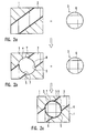
- FIG. 1a shows a rectangle 1 contained in a bitmap file and filled with a color having a predetermined brightness. Further shows FIG. 1 a slanted bar 2 which is an object 3 of the print data. This bar should be inserted into the rectangle 1 such that it is from the Lower left corner of the rectangle 1 extends to the upper right corner. The bar 2 is lighter than the rectangle 1.
- the bar 2 is part of the print data and shown in this as a vector object.
- the bar 2 is thus an object.
- the rectangle 1 is represented by pixels in the bitmap file. It is therefore not an object.
- the area 4 is punched out (knock out) into which the bar 2 is to be inserted ( FIG. 1b ). This avoids that there is a large overlap of the colors of the rectangle 1 and the bar 2, whereby the color of the bar 2 comes true to the original. Since the bar is lighter than the rectangle 1, the punched-out area 4 corresponds exactly to the size of the bar 2.
- the object 3 is inserted in the form of the bar 2 in the bitmap file in the punched-out area 4.
- the object 3 is rasterized to pixels which are entered at the corresponding locations in the bitmap file. Since the object 3 is lighter than the adjacent rectangle 1, the bar 2 in the bitmap file at the edges to the dark cutout of the bitmap file is extended by a trapping area 5 over the punched out area 4 extends beyond.
- the contour of the bar 2 is limited by the darker color of the rectangle 1, which is cut exactly in the shape of the bar.
- the diameter of the circle 6 is greater than the width of the bar 2, so that the circle extends on both sides beyond the bar 2 into the area of the rectangle 1.
- the edge 7 of the circle adjoining the area of the rectangle 1 is punched out exactly with the size of the circle, whereas the edge 8 of the circle adjoining the lighter bar 2 is punched out with a somewhat reduced size becomes.
- the bar 2 extends into the region of the circle 6. This region extending into the region of the circle 6 forms a trapping 5 (FIG. FIG. 2b ).
- the circle itself which forms an object 3 in the print data, is inserted in the bitmap file in the punched-out area 4.
- the circle 6 is rasterized to pixels, which are entered at the appropriate places in the bitmap file. Since the circle 6 is lighter than the area of the rectangle 1, the edge 7 of the circle 6 adjoining the area of the rectangle 1 is widened by an overfill 5 which extends into the area of the rectangle 1.
- the contour of the circle is defined by the edge of the dark color of the rectangle 1.
- the circle is inserted exactly with its size into the bitmap file, since the color of the circle 6 darker than the bar 2 defines the contour of the circle.
- the objects (bar 2, circle 6) explain how to insert them into the bitmap file.
- the objects are individually inserted into the bitmap file, wherein the trapping areas or traps 5 are calculated on the objects themselves and corresponding to the determined trapping is done punching and pasting the objects.
- the objects are rasterized in the bitmap file.
- color was used here in a simplified way.
- a color in multicolor printing usually consists of several colorants (dyes), which are superimposed as required in different proportions. The individual colorants are treated by the control programs in separate color separations. To create a complete picture, all color separations are superimposed. In multicolor printing, punching is done through all the color separations, while the overfills for the individual separations are determined and inserted separately.
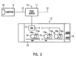
- FIG. 3 a printing system is shown with which colored image data are generated in a user software program 10 running on a user computer 9.
- the image data thus generated are supplied as print data to a print server 11.
- These print data are available in a print data language such as AFP, PostScript, PDF or PCL.
- the print server 11 is connected to a network 12, such as the Internet, and can receive print data from different user computers.
- the print server 11 is connected to a printing device 13.
- the printing device 13 there are several printing stations. In FIG. 3 only three printing stations 14, 15, 16 are shown.
- a printing device for printing with a highlight-color-color requires only two printing stations, for printing with two highlight-color-colors three printing stations and for printing in a full-color space (YMCK) four to six printing stations.
- Each printing station comprises a developer station 14a, 15a, 16a, an exposure unit 14b, 15b, 16b, such as a Leuchtdiodenkamm, and other known per se electrophotographic components, such as a photoconductor drum and a corotron device.
- the data received from the print server 11 is received by a scaleable raster architecture (SRA) print data controller 17 contained in the print device 13.
- SRA scaleable raster architecture
- the trapping process is carried out in real time and the print data is rastered into individual pixels and fed to the printing units 14, 15, 16 or the corresponding light-emitting diode combs 14b, 15b, 16b to form a latent image on the corresponding photoconductor drum.
- the resulting electrostatic images are then developed in a known manner electrophotographically with toner and printed on a recording medium 18, which here comprises individual sheets of paper.
- the raster process in the print data controller can also include a screening process, in which the rastered pixels are machine-specifically processed before being output to the light combs 14b, 15b, 16b.
- the screening process can be downstream of the trapping process or else executed in one step with the trapping process or the raster process. Execution in a common step is possible in particular for 1-bit print data (so-called bilevel print data), the execution in separate steps is generally preferred for print data which are coded in several bits (gray level data, so-called multi-level print data).
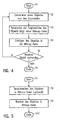
- step S1 a single object is extracted from the print data that into a bitmap file at the appropriate location where it is in the print data.
- step S3 trap areas or overfillings of the object with respect to the color areas or gray scale areas present in the bitmap file and adjacent to the object are calculated.
- the rules according to which the overfillings are calculated will be explained below.
- step S4 the object is inserted into the bitmap file, where the object is rasterized into pixels and the individual pixels are inserted into the bitmap file.
- step S5 it is checked if there is another object to be inserted in the bitmap file. If there is another object, the process flow goes to step S2. Otherwise, the process ends with step S6.
- the objects are individually transferred to the bitmap file.
- the traps are calculated based on the object in terms of the brightness of the color areas of the bitmap file adjacent to the object. This has the advantage that without the creation of additional tables or lists of the shapes of the objects, the complete information of the objects are available. Since the overfills are generated in the bitmap file when punched out or rasterized, it is not necessary to create additional object-level objects for the traps. The determination of the trapping on the basis of the individual objects with regard to the bitmap file and the insertion of the traps in the bitmap file can thus be carried out without delay of the printing process in the print data controller 17 of the printing device 13.
- step S4 The insertion of an object in the bitmap file (step S4) is in the in FIG. 5 shown flowchart shown.
- This procedure starts with step S7.
- Step S8 an area for inserting the respective object is cut out or punched out in the bitmap file.
- overfills are to be considered, which protrude into the area of the object.
- Such overfillings occur, for example, when the object to be pasted is darker than the adjacent color area of the bitmap file.
- Cutting can also be omitted in certain applications (eg overprint).
- the object is scanned into the bitmap file, taking into account traps that extend the object into the adjacent areas of the bitmap file. This is e.g. the case when the object is brighter than the adjacent areas of the bitmap file.
- step S10 this procedure is ended.
- the neutral density of the respective colorant or the respective color can be used to decide which colorant or which color is lighter.
- d is the specific neutral density of the respective colorant, which is usually 0.61 for cyan, 0.76 for magenta, 0.16 for yellow and 1.70 for black.
- c is the concentration of the colorant or the colorant, with which this is applied to the recording medium. The concentration covers a range of values from 0 to 1. c is also called coverage
- a SPREAD is a trapping in which the lighter color or the lighter colorant is extended into the darker color or the darker colorant, respectively.
- a CHOKE is a trapping in which the darker color range is within a lighter color range, with the brighter color range punched out (knock-out) around the darker color range, rendering the darker color gamut as true to color as possible.
- the overfill of the CHOKE is done here by reducing the punched out area of the lighter color area, which in turn expands the lighter color area to the darker color area.
- the trapping used here is called CENTER or CENTER-TRAP and it is symmetrically arranged around the boundary line between the two adjoining surfaces. This retains the original outline.
- CENTER trapping is not used for black or opaque or opaque colors. In black and other opaque colors, the adjacent colors or colorants are always extended under the black or other opaque colors.
- Transparent colors especially transparent lacquers, are generally not trapped.
- Opaque colors are treated as black, which means that the same trapping rules are applied as for black, according to which the adjacent colorants and colors are extended under the opaque color.
- Spot colors are also referred to as highlight color colors.
- the difference in neutral density of adjacent areas is calculated. Only if the difference amount is above a predetermined amount, overfilling is generated.
- This threshold is typically in the range of 0 to 50% and preferably in the range of 5% to 40% of the coverage level with which the colorant is coated on the recording medium.
- a threshold value instead of the neutral density on the basis of the difference of the degree of coverage or the luminance of the adjacent color areas. For multicolor printing, this threshold is applied to each individual colorant.
- Graphic objects are objects defined by vectors, which are usually filled with a monochrome color. For two such contiguous objects, it is easy to decide whether trapping or trapping is to be performed. It is more difficult if the graphic objects are formed in a color gradient. This will be explained below.
- Letter objects are basically treated like graphical objects.
- small letter objects whose stroke width is below a predetermined threshold may experience trapping problems, which causes the trapping to degrade the readability of the characters. Therefore, the width of the letter object is compared to the maximum trapping width. If the width of the letter object is less than twice the maximum trapping width, the trapping width is reduced by a certain amount, for example by 50%. If the width of the object is still less than twice the reduced maximum trapping width, no trapping is performed, but the letter objects are printed as overprint, that is, they are printed on the background color without changing the background color in the area the letter objects is punched out. Thus, no knock-out (recess) is performed.
- Black objects are treated as opaque objects, so that all other colors or colorants are extended under these objects. As black objects become handles all objects whose neutral density is above a certain threshold. This threshold is in the range of 70% to 100% of the neutral density of black. Preferably, it is in the range of 85% to 95% of the neutral density of black. Highlight color fks can always be considered black.
- Highlight Color objects are objects that consist of a single particular colorant.
- the highlight color generally produces a color impression that corresponds to a mixture of several colorants and is often outside the gamut, which can be achieved with the process colorants.
- the Highlight Color color is not mixed with other process colors.
- the calculation of the trapping threshold does not use the degree of coverage but the neutral density of the object.
- Image objects themselves are usually not subjected to trapping. Image objects are trapped at their edges against adjacent other objects. Here there are basically four different possibilities: Center trapping extends both the image and the adjoining vector object. In neutral trapping, each pixel is compared to the neutral density of the adjacent vector object, and the trapping is performed pixel by pixel to one side or the other. However, this can give a diffuse edge impression, which is not desirable.
- a choke image trapping is performed, that is, the adjoining vector object is expanded under the image.
- spread image trapping is performed, meaning that the image is stretched across the object area.
- the preferred trapping rule for image objects is center trapping, which is also the default rule (DEFAULT). Grayscale images are treated like color images. There is no trapping between adjacent image objects.
- trapping parameters may be default values stored in the printing system or may also be individually added trapping parameters to the print document.
- a set of complete trapping parameters is stored in the printing device 13 or in its print data controller 17, so that print data alone with the trapping instruction that trapping is to be executed can be trapped in the printing system.
- This complete set of trapping parameters (default values) may be overridden or replaced by individual trapping parameters conveyed to the print data stream, or these default values may be substituted for the resources discussed below, which may also be stored in the printing system.
- the present method uses two different sets of trapping parameters, one set of trapping parameters controlling trapping parallel to the direction of conveyance of the record carrier in the printer and the other set of trapping parameters trapping across the direction of conveyance of the record carrier in the printing device controls.
- the width of the trap is preferably fixed. This significantly simplifies the creation of traps, since it only has to be determined whether trapping is to be generated and on which side of the interface between two adjoining objects it should be provided or whether it should be centered around the boundary line.
- the width of the trapping is usually one or two pixels. At a resolution of 600 dpi, two pixels correspond to approximately 1.5 mm. For test purposes, it may be appropriate to set the width of the trapping to a few millimeters, as this the traps on the printed image are immediately recognizable.
- the width of the traps is typically 0.02 to 5.0 mm, with the same values for the X and Y directions (Table 1).
- the width of the overfillings for black or opaque colorants is usually twice the width of the overfillings for non-black colorants (Table 2).
- any direction of normal is considered to be on the boundary between two color planes, either vertical or ranging between a vertical line and a line inclined at 45 ° to the vertical.
- the width of the overfill is then adjusted from the boundary line in the direction of the vertical and not in the direction of the normal to the boundary line.
- the Y-direction of a normal standing on a boundary line is any direction between a horizontal and a line inclined by 45 ° with respect to the horizontal or a horizontally extending normal.
- the width of the traps is set here not in the direction of the normal to the boundary line, but in the direction of the horizontal (Y direction).
- Table 3 gives the rules for the difference amount for judging the magnitudes of two adjacent areas. If the difference in the brightnesses of two adjacent areas is less than the difference, no traps are created.
- CYK multi-color space
- each colorant of the object is compared. The lighter colorant is multiplied by the respective coverage ratio and increased by the percentage difference, and if the thus increased lighter colorant is darker than the darker colorant multiplied by its coverage ratio, then no trapping necessary. This comparison is performed between all colorants of the adjacent areas. If a comparison results in the need for trapping, trapping is performed. Colors with a neutral density above a predetermined density limit (black density limit) are treated as black. The default value is 100%. (Table 4). However, it may also be useful in some cases to lower the density limit, eg to a range of 80% to 95%.
- Table 5 shows the black color border, which indicates from which coverage the color black is to be judged as black and not as a gray hue.
- the default value is 1.0. However, values between 0.85 and 1, in particular between 0.85 and 0.95 are also useful.
- a center trap is usually generated only when the neutral density of the two adjacent areas is the same.
- a center trap limit can be used to extend the area within which a center trap is created.
- the center trap limit covers the range of 0.0 to 1.0 (Table 7).
- the center trap limit is applied by multiplying the neutral density of the darker color by the center trap limit, and if the product is smaller than the neutral density of the lighter color, then a center trap is created.
- Table 8 shows some forms of traps, normal overfillings for spread and choke, which are also clipped at the edge area, i. that the trapping that extends into the adjoining color area at the edge does not extend beyond this adjacent color area. There are also overfillings with bevel, a round and a miter.
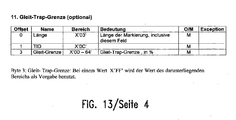
- a sliding-trap limit is provided, which comprises a number range of 0.0 to 1.0. If the value of the sliding trap limit is 1.0, then the transition between the two traps is erratic ( Fig. 8a ). With smaller values of the sliding trap limit, the overfill gradually shifts over the Borderline of the adjacent color areas.
- FIG. 8b shows a gradual transition for a slip-trap limit of about 0.5.
- this can be scaled (trap color scaling).
- the scaling factor can take values in the number range of 0.0 to 1.0. It is also possible that different scaling factors are provided for different colorants. The default value of the scaling factors is 1.0.
- a scaling factor of 1.0 means that the overfill always equals the coverage of the darker colorant, whereas a scaling factor of 0.0 means that the overfill always has the coverage of the lighter colorant. This scaling factor is applied to the difference in coverage of the darker and lighter colorant and added to the coverage of the lighter colorant. This can prevent the traps from becoming too dark or too bright.
- FIG. 9 This diagram shows an example of the hierarchical structure of an IPDS print data stream with several so-called presentation spaces. These presentation spaces each define a specific area in the document to be printed. Several presentation spaces can be superimposed on each other.
- the highest level in the hierarchy of presentation spaces is a medium presentation space 18 which defines the print medium or the print medium.
- This Medium Presentation Space is a finite address space in the print data stream that maps to a full page of the print media. Thus, there is only one medium Presentation Space 18 on one side of a print data medium. The print instructions and print data contained in the medium presentation space thus apply to the entire page.
- All Presentation Spaces can contain print data and print instructions.
- the lowest level of the presentation spaces represent the data object presentation spaces 23 in which the data objects to be printed (graphics and texts) are contained.
- These Data Object Presentation Spaces 23 are merged with the Object Area Presentation Spaces 22, which are intended for special objects.
- the Object Area Presentation Spaces 22 are in turn linked to Page Overlay Presentation Spaces 21.
- Overlays can basically consist of any combination of text, image graphics, barcode and so-called object container data. Overlays are typically used as a kind of form into which the data objects of the lower levels are inserted.
- trapping instructions of a lower level have priority over trapping instructions over a higher level because the printing instructions are at a lower level Level in a more direct relationship to the respective object.
- the medium Overlay Presentation Space 19 a trapping instruction "global trapping enabling / disabling information" is provided, with which the trapping of the print data stream can generally be switched on and off.
- This trapping statement breaks the precedence rule explained above, according to which lower level trapping instructions take precedence over higher level trapping instructions. It allows an operator of the printing system to easily turn trapping on or off by simply pasting this trapping instruction in the top level.
- the trapping instructions can be defined separately in each presentation space with a trapping triplet, which will be explained in more detail below. This allows you to individually control the trapping settings in the individual presentation spaces. Basically, it also applies here that the trapping instructions of a presentation space of a lower level can overrule a corresponding trapping instruction of a presentation space of a higher level. In contrast to the usual practice of the IPDS data stream in the lower levels, for example the Data Object Presentation Spaces, trapping can thus be controlled and this trapping instruction can not be modified by presentation spaces provided at higher levels. In this way, a user who generates a data object to be printed can clearly and irrevocably determine whether and how this data object is subjected to the trapping process.
- trapping parameters in the print data stream are supplemented by the default values stored in the printing device 13 or in the print data controller 17. In practice, it is useful to set as few trapping parameters in the print data stream as the trapping process is very printer-specific. Because the offset of the individual color separations on a print medium usually depends on the mechanical properties of the printing device, so that basic trapping parameters such. the width of a trapping, best defined in the printing device 13. Only trapping parameters specific to the print data itself, e.g. turning off the trapping process for barcode objects should be defined in the print data stream.
- the principle of supplementing the trapping parameters with default values in the printing device makes it possible to keep the creation of the print data stream simple, since only a few, basic and general trapping parameters are defined in the print data stream, which are supplemented in the printing device by further specific trapping parameters.
- the resource structure of the AFP data stream and of the IPDS data stream is used for the control of the trapping method.
- Print data are generated and transmitted by means of the AFP data stream to a print server 11.
- the AFP data stream is processed and converted into an IPDS data stream for output to the printing device 13.
- the print server 11 To do this, run several processes that are controlled by software modules.
- a first software module integrates resource data, such as fonts or overlays, which are called up in the original print data stream into this.
- a second software module, the parsing module checks the print data stream for consistency with given rules.
- the pre-parsing process is preceded by a pre-parsing process, which is carried out by a corresponding software module, in which each resource call and the associated resource file in addition to the resource name an identification date is assigned by the resource to all other resources of the document data stream unique is marked.
- the resource can then be called by means of the resource name and / or the identification data once or several times to display the print data and the resource data on the printing device 13.
- the processes shown here in the print server can also be performed partially or completely in the print data controller 17 of the printing device 13.
- the AFP document data stream includes documents conforming to the MO: DCA standard and each containing reference data to data objects available through the print server 11 and the print data controller 17.
- the resource data can be transferred from the user computer 9 to the print server 11 and the print data controller 17 separately from the MO: DCA document data stream or already stored in the print server 11 and the print data controller 17 as external resources.
- the resource data can also be transmitted together with the document data stream from the user computer 9 to the print server 11 as embedded resource data (so-called inline resources). Further details of a corresponding data processing are in the WO-A1-2004 / 0008379 described.
- the resource data may contain so-called data object resources which contain object data which in particular are referenced multiple times in an identical manner in the document data stream.
- data objects may e.g. Image data, text data, graphics data and / or trapping data.
- the reference to the object resources may be via an object resource library containing characterizing data about the object as well as data about the location of the corresponding object data.
- the library includes a data object resource access table (RAT) that acts as an index table for print server 11 accessing the resource data for print server 11.
- RAT data object resource access table
- the print server 11 receives the MO: DCA document data stream from the user computer 9, converts it to an IPDS document data stream, and sends it to the printing device 13. In the course of the data conversion, it reads the reference information (name) of a data object from the MO: DCA document data stream accesses the stored data resource using the Data Object Resource Access Table (RAT). The complete data of the object is then integrated into the IPDS data stream and sent to the printing device 13. This procedure can be applied equally well if the data is transferred to another output device, such as a printer, instead of a printing device. B. to a color screen, sent.
- RAT Data Object Resource Access Table
- An MO DCA document data stream is structured into data elements that are largely self-explanatory. Structured fields are important components of the MO: DCA structure.
- a structured field is divided into several parts. A first part (introducer) identifies the desired command, indicates the full length of the command, and specifies additional control information, eg, whether additional padding bytes are present.
- the data contained in a structured field can be used as a fixed parameter be encoded, repeating information, keywords and so-called triplets.
- the fixed parameters only have an effect on the structure in which they are contained. Repeat groups specify a grouping of parameters that can occur multiple times.
- Keywords are self-explanatory parameters, typically two bytes, where the first byte is an identification byte for the keyword and the second byte is a data value characterizing the keyword.
- Triplets are self-explanatory parameters that contain a length specification in a first byte, identification information characterizing the triplet in a second byte, and then up to 252 data bytes.
- the mentioned data structures of a MO: DCA document data stream define a syntax that can be evaluated in the course of a parsing process and is flexibly expandable.
- MO DCA data streams have a similar hierarchical structure as the above-mentioned IPDS data streams.
- the resource data can be generated at different locations, the user computer 9, the print server 11 and even by means of a control panel on the printing device 13. These resource data are once sent to the print data controller 17 of the printing device 13 and kept there, so that they can be used again and again if they refer to a corresponding print data stream.
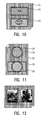
- FIG. 11 a similar example is shown with two presentation spaces 24, in each of which a circular element (Data Object Presentation Space 26) is arranged.
- the upper presentation space 24 is transparent, ie filled with no background color.
- This presentation space 24 contains an instruction that the trapping of objects contained therein is to be carried out with underlying presentation spaces.
- the lower presentation space 24 is filled with an opaque background color, so that the circular element 26 is to be trapped in relation to the presentation space 24 and not to the underlying presentation space 25.
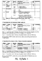
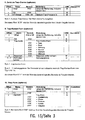
- the fourth column explains the meaning of the triplet.
- the fifth column indicates whether the triplets are optional or mandatory.
- the sixth column contains exceptions.
- Trapping usually depends on the paper direction.
- the trapping parameters in the paper direction therefore often differ from those across the paper direction.
- the Y direction always means parallel to the paper direction and the X direction is rotated 90 ° across the paper direction. If an object is rotated, the print data controller automatically applies the parameters of the corresponding direction.
- an L-unit is usually defined in an IPDS data stream. This L unit can be defined differently for the trapping parameters. In the tables some abbreviations are listed. They mean: TID Trapping ID UPUB L units per UnitBase TS limit Trap-Step-Limit (Difference) BD limit Black Density Limit BC limit Black Color Limit (Black Color Limit) CT limit Center trap limit (center trap limit) TCS Trap Color Scaling (Scaling Factor)
- the trapping process is mainly used in the print data controller 17 (FIG. FIG. 3 ) in real time, so that the print data is fed without delay in the printing process.
- the print data controller 17 does not necessarily have to be integrated in the printing device 13, but can also be arranged outside the printing device 13, for example as a separate raster image processor (RIP).
- the print data controller 12 may include special hardware circuits, such as FPGAs (Free Programmable Gate Arrays) or ASICs (Application Specific Integrated Circuits). It can also be operated on a conventional computer (data processing device) such as a personal computer with one or more Intel® Pentium processors or another processor system with a suitable operating system. It may further be provided with a microprocessor in which an executable computer program is stored, which is designed to carry out the method according to the invention. Of course, this computer program can also be stored on a data medium independent of the printing system.
- the invention is particularly suitable for being implemented as a computer program (software). It can thus be distributed as a computer program module as a file on a data carrier such as a floppy disk or CD-ROM or as a file via a data or communication network. Such and comparable computer program products or computer program elements are embodiments of the invention.
- the process according to the invention can be used in a computer, in a printing device or in a printing system with upstream or downstream data processing devices. It is clear that corresponding computer to which the invention is applied, further, known per se technical devices such as input means (keyboard, mouse, touch screen), a microprocessor, a data or control bus, a display device (monitor, display) and can contain a memory, a hard disk space and a network card.
Landscapes
- Engineering & Computer Science (AREA)
- Theoretical Computer Science (AREA)
- General Engineering & Computer Science (AREA)
- Physics & Mathematics (AREA)
- General Physics & Mathematics (AREA)
- Signal Processing (AREA)
- Multimedia (AREA)
- Record Information Processing For Printing (AREA)
- Facsimile Image Signal Circuits (AREA)
- Editing Of Facsimile Originals (AREA)
- Color Image Communication Systems (AREA)
- Inking, Control Or Cleaning Of Printing Machines (AREA)
- Manufacture Or Reproduction Of Printing Formes (AREA)
- Fax Reproducing Arrangements (AREA)
Claims (15)
- Procédé destiné à intercepter des données d'impression comprenant une pluralité d'objets non tramés, les objets étant transférés individuellement dans un fichier de points d'image et respectivement les étapes suivantes étant mises en oeuvre à cet effet, consistant à :- déterminer au moins un surdosage pour l'objet respectif par rapport aux zones de couleur adjacentes à l'objet dans le fichier de points d'image conformément à des règles d'interception prédéfinies, et- insérer l'objet et le ou les surdosages dans le fichier de points d'image, l'objet et le surdosage étant tramés dans le fichier de points d'image lors de l'insertion.
- procédé selon la revendication 1,
caractérisé en ce que les données d'impression sont mises à disposition pendant le transfert des objets individuels dans le fichier de points d'image. - Procédé selon la revendication 1 ou 2,
caractérisé en ce que lors de l'insertion de l'objet dans le fichier de points d'image, la zone dans laquelle l'objet doit être inséré est découpée du fichier de points d'image avant que l'objet ne soit tramé dans le fichier de points d'image, la zone à découper pouvant être réduite en fonction du surdosage préalablement déterminé. - Procédé selon la revendication 3,
caractérisé en ce que dans le cas d'une impression multicolore, les zones pour les objets à introduire sont découpées à travers toutes les sélections de couleur. - Procédé selon l'une quelconque des revendications 1 à 4,
caractérisé en ce que lors d'une impression multicolore, les surdosages pour les sélections de couleur individuelles sont déterminés et insérés séparément. - Procédé selon l'une quelconque des revendications 1 à 5,
caractérisé en ce que les surdosages ne sont déterminés qu'aux bords respectivement d'un des objets lorsque la luminosité de l'objet respectif par rapport à la zone adjacente se différencie d'une valeur différentielle supérieure à une valeur seuil prédéfinie. - Procédé selon l'une quelconque des revendications 1 à 6,
caractérisé en ce que dans le cas de surdosages dans la zone d'une pointe étroite et longue, la pointe ne s'étend pas au-delà de la largeur du surdosage dans la direction X ou dans la direction Y par rapport au point le plus extérieur de l'objet non intercepté. - Procédé selon l'une quelconque des revendications 1 à 7,
caractérisé en ce que le procédé est mis en oeuvre dans un dispositif de commande de données d'impression (17) d'un appareil d'impression (13). - Procédé selon l'une quelconque des revendications 1 à 8,
caractérisé en ce que les données d'impression sont transférées dans un flux de données d'impression et le flux de données d'impression référence des données de ressource contenant des paramètres d'interception et/ou des instructions d'interception. - Procédé selon l'une quelconque des revendications 1 à 9,
caractérisé en ce que les données d'impression sont transférées dans un flux de données d'impression conjointement avec des instructions d'interception sur un appareil d'impression, et le flux de données d'impression est structuré dans différents plans, plus le plan étant élevé, plus la zone sur laquelle les instructions contenues dans le plan respectif agissent étant importante et les instructions d'interception venant de plans inférieurs étant prioritaires sur les instructions d'interception provenant de plans supérieurs. - Procédé selon la revendication 10,
caractérisé en ce qu'une instruction d'interception permettant d'activer ou de désactiver l'interception dans toute la zone du plan le plus élevé est prévue dans le plan le plus élevé. - Procédé selon l'une quelconque des revendications 10 ou 11,
caractérisé en ce que le flux de données d'impression est un flux de données AFP/IPDS. - Procédé selon la revendication 12,
caractérisé en ce que les instructions d'interception réglant l'interception à l'intérieur de l'espace de présentation respectif sont contenues dans les espaces de présentation contenus dans le flux de données d'impression AFP/IPDS, les espaces de présentation étant disposés dans différents plans. - Système d'impression destiné à intercepter des données d'impression, comprenant un dispositif de commande de données d'impression (17) et plusieurs groupes d'impression (17), le dispositif de commande de données d'impression (17) étant destiné à mettre en oeuvre le procédé d'interception selon l'une quelconque des revendications 1 à 13.
- Programme informatique pour un système d'impression selon la revendication 14, destiné à mettre en oeuvre le procédé selon l'une quelconque des revendications 1 à 13.
Applications Claiming Priority (2)
| Application Number | Priority Date | Filing Date | Title |
|---|---|---|---|
| DE102006055587A DE102006055587B4 (de) | 2006-11-24 | 2006-11-24 | Verfahren, Computerprogramm und Drucksystem zum Trapping von Druckdaten mit einer Vielzahl von Objekten |
| PCT/EP2007/062690 WO2008062038A1 (fr) | 2006-11-24 | 2007-11-22 | Procédé, programme informatique et système d'impression pour intercepter des données d'impression |
Publications (2)
| Publication Number | Publication Date |
|---|---|
| EP2092730A1 EP2092730A1 (fr) | 2009-08-26 |
| EP2092730B1 true EP2092730B1 (fr) | 2013-05-08 |
Family
ID=39223486
Family Applications (1)
| Application Number | Title | Priority Date | Filing Date |
|---|---|---|---|
| EP07822815.2A Active EP2092730B1 (fr) | 2006-11-24 | 2007-11-22 | Procédé, programme informatique et système d'impression pour intercepter des données d'impression |
Country Status (6)
| Country | Link |
|---|---|
| US (1) | US8705136B2 (fr) |
| EP (1) | EP2092730B1 (fr) |
| JP (1) | JP5096482B2 (fr) |
| CN (1) | CN101558635A (fr) |
| DE (1) | DE102006055587B4 (fr) |
| WO (1) | WO2008062038A1 (fr) |
Families Citing this family (9)
| Publication number | Priority date | Publication date | Assignee | Title |
|---|---|---|---|---|
| DE102006055587B4 (de) | 2006-11-24 | 2008-12-11 | OCé PRINTING SYSTEMS GMBH | Verfahren, Computerprogramm und Drucksystem zum Trapping von Druckdaten mit einer Vielzahl von Objekten |
| DE102006055624B4 (de) | 2006-11-24 | 2008-12-11 | OCé PRINTING SYSTEMS GMBH | Verfahren, Computerprogramm und Drucksystem zum Trapping von Druckdaten mit einer Vielzahl von Objekten |
| US8417046B1 (en) | 2008-11-10 | 2013-04-09 | Marvell International Ltd. | Shadow and highlight image enhancement |
| CN102111529B (zh) * | 2009-12-25 | 2012-08-29 | 北大方正集团有限公司 | 一种对渐变图元对象进行陷印处理的方法及装置 |
| US8958636B1 (en) * | 2010-07-28 | 2015-02-17 | Marvell International Ltd. | Configurable color trapping |
| DE102011000001B4 (de) | 2011-01-03 | 2016-09-29 | Océ Printing Systems GmbH & Co. KG | Verfahren zum Steuern einer Druck-Vorrichtung sowie entsprechende Druck-Vorrichtung, Computersystem und Computerprogrammprodukt |
| DE102013107996A1 (de) * | 2013-07-26 | 2015-02-19 | Manroland Web Systems Gmbh | Verfahren und Vorrichtung zum Herstellen von Druckformen sowie Druckverfahren |
| DE102015220470A1 (de) | 2014-11-20 | 2016-05-25 | Heidelberger Druckmaschinen Aktiengesellschaft | Verfahren zur Erzeugung von PDF Trapping-Objekten ohne Kenntnis der Konturbeschreibung |
| CN112549553B (zh) * | 2020-10-27 | 2023-03-10 | 共享智能装备有限公司 | 3d打印方法及3d打印机 |
Family Cites Families (42)
| Publication number | Priority date | Publication date | Assignee | Title |
|---|---|---|---|---|
| JPH01170169A (ja) | 1987-12-25 | 1989-07-05 | Dainippon Screen Mfg Co Ltd | 多色印刷のための画像図形修正処理方法 |
| JPH0817445B2 (ja) | 1990-11-06 | 1996-02-21 | 大日本スクリーン製造株式会社 | 画像のカブセ処理方法 |
| US5542052A (en) | 1991-03-04 | 1996-07-30 | Adobe Systems Incorporated | Applying traps to a printed page specified in a page description language format |
| US5666543A (en) | 1994-03-23 | 1997-09-09 | Adobe Systems Incorporated | Method of trapping graphical objects in a desktop publishing program |
| US5581667A (en) | 1994-12-23 | 1996-12-03 | Xerox Corporation | Electronic trapping system for digitized text and images |
| US5768488A (en) | 1995-02-24 | 1998-06-16 | International Business Machines Corporation | Enhanced page placement for multiple-up presentation |
| US5923821A (en) | 1996-09-27 | 1999-07-13 | Xerox Corporation | Digital image trapping system |
| CA2210552C (fr) | 1996-09-27 | 2001-05-15 | Xerox Corporation | Systeme et methode d'attenuation de l'effet de halo visuel. |
| US6262747B1 (en) | 1996-10-29 | 2001-07-17 | Adobe Systems Incorporated | Device-independent trapping |
| JP3779400B2 (ja) * | 1996-11-28 | 2006-05-24 | 株式会社東芝 | 画像処理方法 |
| CA2282846C (fr) | 1997-03-03 | 2007-05-15 | Oce Printing Systems Gmbh | Dispositif d'impression et de copie pour realiser une impression monochrome ou en couleurs, adaptee a des performances, sur un ou deux cotes d'un support |
| US5982997A (en) | 1997-08-14 | 1999-11-09 | International Business Machines Inc. | Data stream protocol for immediate job switching |
| US6097498A (en) | 1997-09-12 | 2000-08-01 | International Business Machines Corporation | Thin layer protocol™ for printer management |
| US6236754B1 (en) | 1998-01-08 | 2001-05-22 | Xerox Corporation | Image modification to reduce susceptibility to misregistration |
| US6535295B1 (en) * | 1998-08-24 | 2003-03-18 | International Business Machines Corporation | Virtual printer with asynchronous job and device status |
| JP4234281B2 (ja) * | 1998-10-22 | 2009-03-04 | ゼロックス コーポレイション | プリントシステム |
| US6483599B1 (en) * | 1998-12-29 | 2002-11-19 | Pitney Bowes Inc. | System and method for separating a print stream into an electronic document print stream and a physical document print stream |
| DE19912511A1 (de) | 1999-03-19 | 2000-09-21 | Heidelberger Druckmasch Ag | Verfahren zur Erzeugung von Überfüllungskonturen in einer Druckseite |
| US6549303B1 (en) * | 1999-09-20 | 2003-04-15 | Hewlett-Packard Company | Trapping methods and arrangements for use in printing color images |
| US6559966B1 (en) * | 2000-01-10 | 2003-05-06 | Imagex, Inc. | Trapping of graphic image files |
| US7265854B1 (en) | 2000-01-24 | 2007-09-04 | International Business Machines Corporation | Method and apparatus for managing complex presentation objects using globally-unique identifiers |
| US6992798B2 (en) * | 2000-03-09 | 2006-01-31 | Agfa-Bevaert N.V. | Apparatus, product, and method of trapping using a distance buffer |
| US6809839B1 (en) | 2000-06-02 | 2004-10-26 | Global Graphics Software Limited | System and method for rendering printing traps with application of color transformations |
| DE10123885A1 (de) | 2001-05-16 | 2002-12-12 | Bayer Ag | Verfahren zum Abfüllen von feuchtem, klebrigem Schüttgut |
| DE10206706B4 (de) | 2002-02-18 | 2006-03-23 | OCé PRINTING SYSTEMS GMBH | Verfahren, Gerätesysteme und Computerprogramme zum Erzeugen und Verarbeiten eines Dokumentendatenstroms, der strukturierte Felder enthält |
| GB0216649D0 (en) | 2002-06-17 | 2002-08-28 | Storm Mason R | Identity verification |
| JP4281414B2 (ja) * | 2003-05-22 | 2009-06-17 | セイコーエプソン株式会社 | バーコードまたは二次元コードの印刷システム、バーコードまたは二次元コードのフォント設定方法、およびバーコードまたは二次元コードのフォント設定プログラム |
| DE10325843B4 (de) | 2003-06-06 | 2005-06-23 | OCé PRINTING SYSTEMS GMBH | Verfahren, Drucksystem, Computer und Computerprogramm zum Verwalten von Resourcen zur Verwendung in einem resourcenbasierten Dokumentendatenstrom |
| US7359530B2 (en) * | 2003-06-06 | 2008-04-15 | Global Graphics Software Limited | Object-based raster trapping |
| DE10329339B4 (de) | 2003-06-30 | 2007-04-26 | OCé PRINTING SYSTEMS GMBH | Verfahren und Vorrichtung zum Aufbereiten einer Bildpunktdatei |
| JP4142614B2 (ja) | 2003-11-10 | 2008-09-03 | 大日本スクリーン製造株式会社 | トラッピング方法、トラッピングプログラム、トラッピング装置および印刷システム |
| US7436546B2 (en) | 2004-05-07 | 2008-10-14 | Infoprint Solutions Company, Llc | Method and apparatus for color management |
| US7391536B2 (en) * | 2004-07-09 | 2008-06-24 | Xerox Corporation | Method for smooth trapping suppression of small graphical objects using color interpolation |
| US20060033971A1 (en) * | 2004-08-13 | 2006-02-16 | Quark, Inc. | Automated trapping system for desktop publishing |
| US7522313B2 (en) * | 2004-11-23 | 2009-04-21 | Xerox Corporation | Intelligent trapping |
| DE102004062841A1 (de) * | 2004-12-27 | 2006-07-13 | OCé PRINTING SYSTEMS GMBH | Verfahren, Computerprogramm, Computer und Drucksysteme zum Trapping von Bilddaten |
| DE102006008768A1 (de) | 2006-02-24 | 2007-08-30 | OCé PRINTING SYSTEMS GMBH | Verfahren und Vorrichtung zum Verarbeiten eines Druckdatenstroms zum Erzeugen mehrfarbiger Druckbilder mit Hilfe eines Hochleistungsdrucksystems |
| US8199359B2 (en) * | 2006-04-28 | 2012-06-12 | Kyocera Mita Corporation | System and method for reducing visibility of registration errors in an image to be printed using a digital color printer by convolution with a laplacian kernel |
| DE102006055624B4 (de) | 2006-11-24 | 2008-12-11 | OCé PRINTING SYSTEMS GMBH | Verfahren, Computerprogramm und Drucksystem zum Trapping von Druckdaten mit einer Vielzahl von Objekten |
| DE102006055587B4 (de) | 2006-11-24 | 2008-12-11 | OCé PRINTING SYSTEMS GMBH | Verfahren, Computerprogramm und Drucksystem zum Trapping von Druckdaten mit einer Vielzahl von Objekten |
| DE102006055626B4 (de) | 2006-11-24 | 2008-12-04 | OCé PRINTING SYSTEMS GMBH | Verfahren, Computerprogramm und Drucksystem zum Trapping von Druckdaten mit einer Vielzahl von Objekten |
| DE102006055625B4 (de) | 2006-11-24 | 2008-12-04 | OCé PRINTING SYSTEMS GMBH | Verfahren, Computerprogramm und Drucksystem zum Trapping von Druckdaten mit einer Vielzahl von Objekten |
-
2006
- 2006-11-24 DE DE102006055587A patent/DE102006055587B4/de not_active Withdrawn - After Issue
-
2007
- 2007-11-22 JP JP2009537639A patent/JP5096482B2/ja not_active Expired - Fee Related
- 2007-11-22 WO PCT/EP2007/062690 patent/WO2008062038A1/fr active Application Filing
- 2007-11-22 EP EP07822815.2A patent/EP2092730B1/fr active Active
- 2007-11-22 CN CNA2007800418665A patent/CN101558635A/zh active Pending
- 2007-11-22 US US12/514,612 patent/US8705136B2/en active Active
Also Published As
| Publication number | Publication date |
|---|---|
| WO2008062038A1 (fr) | 2008-05-29 |
| CN101558635A (zh) | 2009-10-14 |
| EP2092730A1 (fr) | 2009-08-26 |
| JP2010510739A (ja) | 2010-04-02 |
| DE102006055587A1 (de) | 2008-05-29 |
| US8705136B2 (en) | 2014-04-22 |
| DE102006055587B4 (de) | 2008-12-11 |
| US20100060940A1 (en) | 2010-03-11 |
| JP5096482B2 (ja) | 2012-12-12 |
Similar Documents
| Publication | Publication Date | Title |
|---|---|---|
| EP2092730B1 (fr) | Procédé, programme informatique et système d'impression pour intercepter des données d'impression | |
| DE102006055624B4 (de) | Verfahren, Computerprogramm und Drucksystem zum Trapping von Druckdaten mit einer Vielzahl von Objekten | |
| DE4106458C2 (de) | Graphische Datenverarbeitungseinrichtung zum Erzeugen eines Tones eines Randbildelements aus Vektordaten | |
| DE60305573T2 (de) | Verfahren zur Darstellung von gemischten Bildrasterinhaltsebenen | |
| DE69832242T2 (de) | Verfahren und Vorrichtung zur Verarbeitung und Wiedergabe von objektorientierten, neutralen Bilddaten | |
| EP1842361B1 (fr) | Procede, programme d'ordinateur, ordinateur et systeme d'impression pour le piegeage de donnees image | |
| EP1692640B1 (fr) | Procede et systeme pour traiter des donnees d'impression concernant au moins une page a imprimer | |
| DE60033479T2 (de) | Bilderzeugungssystem und -verfahren | |
| EP1989873B1 (fr) | Procede et dispositif de traitement d'un train de donnees d'impression pour la production d'images imprimees multicolores au moyen d'un systeme d'impression a haut rendement | |
| DE102006055625B4 (de) | Verfahren, Computerprogramm und Drucksystem zum Trapping von Druckdaten mit einer Vielzahl von Objekten | |
| DE102016212699A1 (de) | System und Verfahren zum Erzeugen eines klaren Farbmittels auf ausgeschossenen Mehrfachdurchlaufseiten | |
| EP1290628B1 (fr) | Procede de production et d'emission d'au moins une page imprimee | |
| DE102007037032B4 (de) | Verfahren zum Erzeugen eines Templates | |
| US6246419B1 (en) | PDL operator overloading for line width management | |
| DE102006055626B4 (de) | Verfahren, Computerprogramm und Drucksystem zum Trapping von Druckdaten mit einer Vielzahl von Objekten | |
| EP1980094A2 (fr) | Procédé, produit programme d'ordinateur et dispositif de production et de traitement données documents liées aux ressources de gestion de couleur indexées | |
| US6201551B1 (en) | PDL operator overloading for line width management | |
| DE10257871A1 (de) | System und Verfahren für eine Benachrichtigung bezüglich einer Farbpaletten-Unzulänglichkeit | |
| DE102007036985B4 (de) | Verfahren, System und Computerprogrammprodukt zum automatischen Aufbereiten von Dokumentenbearbeitungsdaten | |
| DE102007036986B4 (de) | Verfahren zum automatischen Aufbereiten und Trennen von in einem Dokumentendatenstrom enthaltenen Dokumentenbearbeitungsdaten | |
| DE102008007339B4 (de) | Verfahren und Vorrichtung zum Erzeugen von Druckdaten | |
| DE10126625A1 (de) | Bilddruckvorrichtungen mit AM/FM-Halbtonbildung unter Selbstbestimmung einer Punktgröße und Verfahren zum Implementieren derselben | |
| DE102015105818B4 (de) | Verfahren zum visuellen Überprüfen eines in einer Druckdatensprache vorliegenden Druckdatenstroms |
Legal Events
| Date | Code | Title | Description |
|---|---|---|---|
| PUAI | Public reference made under article 153(3) epc to a published international application that has entered the european phase |
Free format text: ORIGINAL CODE: 0009012 |
|
| 17P | Request for examination filed |
Effective date: 20090520 |
|
| AK | Designated contracting states |
Kind code of ref document: A1 Designated state(s): AT BE BG CH CY CZ DE DK EE ES FI FR GB GR HU IE IS IT LI LT LU LV MC MT NL PL PT RO SE SI SK TR |
|
| DAX | Request for extension of the european patent (deleted) | ||
| GRAP | Despatch of communication of intention to grant a patent |
Free format text: ORIGINAL CODE: EPIDOSNIGR1 |
|
| GRAS | Grant fee paid |
Free format text: ORIGINAL CODE: EPIDOSNIGR3 |
|
| GRAA | (expected) grant |
Free format text: ORIGINAL CODE: 0009210 |
|
| AK | Designated contracting states |
Kind code of ref document: B1 Designated state(s): AT BE BG CH CY CZ DE DK EE ES FI FR GB GR HU IE IS IT LI LT LU LV MC MT NL PL PT RO SE SI SK TR |
|
| REG | Reference to a national code |
Ref country code: GB Ref legal event code: FG4D Free format text: NOT ENGLISH |
|
| REG | Reference to a national code |
Ref country code: CH Ref legal event code: EP Ref country code: AT Ref legal event code: REF Ref document number: 611557 Country of ref document: AT Kind code of ref document: T Effective date: 20130515 |
|
| REG | Reference to a national code |
Ref country code: IE Ref legal event code: FG4D Free format text: LANGUAGE OF EP DOCUMENT: GERMAN |
|
| REG | Reference to a national code |
Ref country code: DE Ref legal event code: R096 Ref document number: 502007011735 Country of ref document: DE Effective date: 20130704 |
|
| REG | Reference to a national code |
Ref country code: DE Ref legal event code: R082 Ref document number: 502007011735 Country of ref document: DE Representative=s name: PATENTANWAELTE SCHAUMBURG, THOENES, THURN, LAN, DE |
|
| REG | Reference to a national code |
Ref country code: DE Ref legal event code: R082 Ref document number: 502007011735 Country of ref document: DE Representative=s name: PATENTANWAELTE SCHAUMBURG, THOENES, THURN, LAN, DE Effective date: 20130819 Ref country code: DE Ref legal event code: R081 Ref document number: 502007011735 Country of ref document: DE Owner name: OCE PRINTING SYSTEMS GMBH & CO. KG, DE Free format text: FORMER OWNER: OCE PRINTING SYSTEMS GMBH, 85586 POING, DE Effective date: 20130819 Ref country code: DE Ref legal event code: R082 Ref document number: 502007011735 Country of ref document: DE Representative=s name: SCHAUMBURG & PARTNER PATENTANWAELTE GBR, DE Effective date: 20130819 Ref country code: DE Ref legal event code: R082 Ref document number: 502007011735 Country of ref document: DE Representative=s name: SCHAUMBURG & PARTNER PATENTANWAELTE MBB, DE Effective date: 20130819 Ref country code: DE Ref legal event code: R082 Ref document number: 502007011735 Country of ref document: DE Representative=s name: SCHAUMBURG UND PARTNER PATENTANWAELTE MBB, DE Effective date: 20130819 |
|
| REG | Reference to a national code |
Ref country code: LT Ref legal event code: MG4D |
|
| REG | Reference to a national code |
Ref country code: NL Ref legal event code: VDEP Effective date: 20130508 |
|
| PG25 | Lapsed in a contracting state [announced via postgrant information from national office to epo] |
Ref country code: GR Free format text: LAPSE BECAUSE OF FAILURE TO SUBMIT A TRANSLATION OF THE DESCRIPTION OR TO PAY THE FEE WITHIN THE PRESCRIBED TIME-LIMIT Effective date: 20130809 Ref country code: PT Free format text: LAPSE BECAUSE OF FAILURE TO SUBMIT A TRANSLATION OF THE DESCRIPTION OR TO PAY THE FEE WITHIN THE PRESCRIBED TIME-LIMIT Effective date: 20130909 Ref country code: ES Free format text: LAPSE BECAUSE OF FAILURE TO SUBMIT A TRANSLATION OF THE DESCRIPTION OR TO PAY THE FEE WITHIN THE PRESCRIBED TIME-LIMIT Effective date: 20130819 Ref country code: SI Free format text: LAPSE BECAUSE OF FAILURE TO SUBMIT A TRANSLATION OF THE DESCRIPTION OR TO PAY THE FEE WITHIN THE PRESCRIBED TIME-LIMIT Effective date: 20130508 Ref country code: LT Free format text: LAPSE BECAUSE OF FAILURE TO SUBMIT A TRANSLATION OF THE DESCRIPTION OR TO PAY THE FEE WITHIN THE PRESCRIBED TIME-LIMIT Effective date: 20130508 Ref country code: SE Free format text: LAPSE BECAUSE OF FAILURE TO SUBMIT A TRANSLATION OF THE DESCRIPTION OR TO PAY THE FEE WITHIN THE PRESCRIBED TIME-LIMIT Effective date: 20130508 Ref country code: FI Free format text: LAPSE BECAUSE OF FAILURE TO SUBMIT A TRANSLATION OF THE DESCRIPTION OR TO PAY THE FEE WITHIN THE PRESCRIBED TIME-LIMIT Effective date: 20130508 Ref country code: IS Free format text: LAPSE BECAUSE OF FAILURE TO SUBMIT A TRANSLATION OF THE DESCRIPTION OR TO PAY THE FEE WITHIN THE PRESCRIBED TIME-LIMIT Effective date: 20130908 |
|
| PG25 | Lapsed in a contracting state [announced via postgrant information from national office to epo] |
Ref country code: CY Free format text: LAPSE BECAUSE OF FAILURE TO SUBMIT A TRANSLATION OF THE DESCRIPTION OR TO PAY THE FEE WITHIN THE PRESCRIBED TIME-LIMIT Effective date: 20130508 Ref country code: BG Free format text: LAPSE BECAUSE OF FAILURE TO SUBMIT A TRANSLATION OF THE DESCRIPTION OR TO PAY THE FEE WITHIN THE PRESCRIBED TIME-LIMIT Effective date: 20130808 Ref country code: PL Free format text: LAPSE BECAUSE OF FAILURE TO SUBMIT A TRANSLATION OF THE DESCRIPTION OR TO PAY THE FEE WITHIN THE PRESCRIBED TIME-LIMIT Effective date: 20130508 |
|
| PG25 | Lapsed in a contracting state [announced via postgrant information from national office to epo] |
Ref country code: LV Free format text: LAPSE BECAUSE OF FAILURE TO SUBMIT A TRANSLATION OF THE DESCRIPTION OR TO PAY THE FEE WITHIN THE PRESCRIBED TIME-LIMIT Effective date: 20130508 |
|
| PG25 | Lapsed in a contracting state [announced via postgrant information from national office to epo] |
Ref country code: CZ Free format text: LAPSE BECAUSE OF FAILURE TO SUBMIT A TRANSLATION OF THE DESCRIPTION OR TO PAY THE FEE WITHIN THE PRESCRIBED TIME-LIMIT Effective date: 20130508 Ref country code: DK Free format text: LAPSE BECAUSE OF FAILURE TO SUBMIT A TRANSLATION OF THE DESCRIPTION OR TO PAY THE FEE WITHIN THE PRESCRIBED TIME-LIMIT Effective date: 20130508 Ref country code: EE Free format text: LAPSE BECAUSE OF FAILURE TO SUBMIT A TRANSLATION OF THE DESCRIPTION OR TO PAY THE FEE WITHIN THE PRESCRIBED TIME-LIMIT Effective date: 20130508 Ref country code: SK Free format text: LAPSE BECAUSE OF FAILURE TO SUBMIT A TRANSLATION OF THE DESCRIPTION OR TO PAY THE FEE WITHIN THE PRESCRIBED TIME-LIMIT Effective date: 20130508 |
|
| PG25 | Lapsed in a contracting state [announced via postgrant information from national office to epo] |
Ref country code: IT Free format text: LAPSE BECAUSE OF FAILURE TO SUBMIT A TRANSLATION OF THE DESCRIPTION OR TO PAY THE FEE WITHIN THE PRESCRIBED TIME-LIMIT Effective date: 20130508 Ref country code: RO Free format text: LAPSE BECAUSE OF FAILURE TO SUBMIT A TRANSLATION OF THE DESCRIPTION OR TO PAY THE FEE WITHIN THE PRESCRIBED TIME-LIMIT Effective date: 20130508 Ref country code: NL Free format text: LAPSE BECAUSE OF FAILURE TO SUBMIT A TRANSLATION OF THE DESCRIPTION OR TO PAY THE FEE WITHIN THE PRESCRIBED TIME-LIMIT Effective date: 20130508 |
|
| PLBE | No opposition filed within time limit |
Free format text: ORIGINAL CODE: 0009261 |
|
| STAA | Information on the status of an ep patent application or granted ep patent |
Free format text: STATUS: NO OPPOSITION FILED WITHIN TIME LIMIT |
|
| 26N | No opposition filed |
Effective date: 20140211 |
|
| REG | Reference to a national code |
Ref country code: DE Ref legal event code: R097 Ref document number: 502007011735 Country of ref document: DE Effective date: 20140211 |
|
| BERE | Be: lapsed |
Owner name: OCE PRINTING SYSTEMS G.M.B.H. Effective date: 20131130 |
|
| REG | Reference to a national code |
Ref country code: FR Ref legal event code: TP Owner name: OCE PRINTING SYSTEMS GMBH & CO. KG, DE Effective date: 20140513 |
|
| REG | Reference to a national code |
Ref country code: CH Ref legal event code: PL |
|
| PG25 | Lapsed in a contracting state [announced via postgrant information from national office to epo] |
Ref country code: LI Free format text: LAPSE BECAUSE OF NON-PAYMENT OF DUE FEES Effective date: 20131130 Ref country code: MC Free format text: LAPSE BECAUSE OF FAILURE TO SUBMIT A TRANSLATION OF THE DESCRIPTION OR TO PAY THE FEE WITHIN THE PRESCRIBED TIME-LIMIT Effective date: 20130508 Ref country code: CH Free format text: LAPSE BECAUSE OF NON-PAYMENT OF DUE FEES Effective date: 20131130 |
|
| REG | Reference to a national code |
Ref country code: IE Ref legal event code: MM4A |
|
| PG25 | Lapsed in a contracting state [announced via postgrant information from national office to epo] |
Ref country code: BE Free format text: LAPSE BECAUSE OF NON-PAYMENT OF DUE FEES Effective date: 20131130 |
|
| REG | Reference to a national code |
Ref country code: GB Ref legal event code: 732E Free format text: REGISTERED BETWEEN 20140904 AND 20140910 |
|
| PG25 | Lapsed in a contracting state [announced via postgrant information from national office to epo] |
Ref country code: IE Free format text: LAPSE BECAUSE OF NON-PAYMENT OF DUE FEES Effective date: 20131122 |
|
| REG | Reference to a national code |
Ref country code: AT Ref legal event code: MM01 Ref document number: 611557 Country of ref document: AT Kind code of ref document: T Effective date: 20131122 |
|
| PG25 | Lapsed in a contracting state [announced via postgrant information from national office to epo] |
Ref country code: AT Free format text: LAPSE BECAUSE OF NON-PAYMENT OF DUE FEES Effective date: 20131122 |
|
| REG | Reference to a national code |
Ref country code: DE Ref legal event code: R082 Ref document number: 502007011735 Country of ref document: DE Representative=s name: SCHAUMBURG & PARTNER PATENTANWAELTE GBR, DE Ref country code: DE Ref legal event code: R082 Ref document number: 502007011735 Country of ref document: DE Representative=s name: SCHAUMBURG & PARTNER PATENTANWAELTE MBB, DE Ref country code: DE Ref legal event code: R082 Ref document number: 502007011735 Country of ref document: DE Representative=s name: SCHAUMBURG UND PARTNER PATENTANWAELTE MBB, DE |
|
| PG25 | Lapsed in a contracting state [announced via postgrant information from national office to epo] |
Ref country code: TR Free format text: LAPSE BECAUSE OF FAILURE TO SUBMIT A TRANSLATION OF THE DESCRIPTION OR TO PAY THE FEE WITHIN THE PRESCRIBED TIME-LIMIT Effective date: 20130508 |
|
| PG25 | Lapsed in a contracting state [announced via postgrant information from national office to epo] |
Ref country code: HU Free format text: LAPSE BECAUSE OF FAILURE TO SUBMIT A TRANSLATION OF THE DESCRIPTION OR TO PAY THE FEE WITHIN THE PRESCRIBED TIME-LIMIT; INVALID AB INITIO Effective date: 20071122 Ref country code: LU Free format text: LAPSE BECAUSE OF NON-PAYMENT OF DUE FEES Effective date: 20131122 |
|
| PG25 | Lapsed in a contracting state [announced via postgrant information from national office to epo] |
Ref country code: MT Free format text: LAPSE BECAUSE OF FAILURE TO SUBMIT A TRANSLATION OF THE DESCRIPTION OR TO PAY THE FEE WITHIN THE PRESCRIBED TIME-LIMIT Effective date: 20130508 |
|
| REG | Reference to a national code |
Ref country code: FR Ref legal event code: PLFP Year of fee payment: 9 |
|
| REG | Reference to a national code |
Ref country code: FR Ref legal event code: PLFP Year of fee payment: 10 |
|
| REG | Reference to a national code |
Ref country code: FR Ref legal event code: PLFP Year of fee payment: 11 |
|
| PGFP | Annual fee paid to national office [announced via postgrant information from national office to epo] |
Ref country code: GB Payment date: 20231123 Year of fee payment: 17 |
|
| PGFP | Annual fee paid to national office [announced via postgrant information from national office to epo] |
Ref country code: FR Payment date: 20231122 Year of fee payment: 17 Ref country code: DE Payment date: 20231124 Year of fee payment: 17 |