EP1842361B1 - Method, computer program, computer and printing system for trapping image data - Google Patents
Method, computer program, computer and printing system for trapping image data Download PDFInfo
- Publication number
- EP1842361B1 EP1842361B1 EP05825216A EP05825216A EP1842361B1 EP 1842361 B1 EP1842361 B1 EP 1842361B1 EP 05825216 A EP05825216 A EP 05825216A EP 05825216 A EP05825216 A EP 05825216A EP 1842361 B1 EP1842361 B1 EP 1842361B1
- Authority
- EP
- European Patent Office
- Prior art keywords
- image data
- image
- colour
- transformed
- objects
- Prior art date
- Legal status (The legal status is an assumption and is not a legal conclusion. Google has not performed a legal analysis and makes no representation as to the accuracy of the status listed.)
- Expired - Fee Related
Links
Images


Classifications
-
- H—ELECTRICITY
- H04—ELECTRIC COMMUNICATION TECHNIQUE
- H04N—PICTORIAL COMMUNICATION, e.g. TELEVISION
- H04N1/00—Scanning, transmission or reproduction of documents or the like, e.g. facsimile transmission; Details thereof
- H04N1/46—Colour picture communication systems
- H04N1/56—Processing of colour picture signals
- H04N1/58—Edge or detail enhancement; Noise or error suppression, e.g. colour misregistration correction
Definitions
- the invention relates to a method, a computer program, a computer and a printing system for trapping image data.
- Colored documents or document parts such as As images, color graphics or the like, are usually described by image data, which are divided into color separations.
- This type of data structure corresponds to many print output methods or apparatus that print the image data in color separations on a record carrier, e.g. in the colors yellow (Y), magenta (M), cyan (C) and black (K) or in black and one or more so-called highlight color colors or the Océ Custom Tone® colors.
- the Applicant develops and distributes corresponding digital electrographic printing systems. They are eg in the publication " The World of Printers, Technologies of Océ Printing Systems ", Dr. Gerd Goldmann (ed.), Océ Printing Systems GmbH, Poing, Ed. 7 (2002 ). Various offset and digital printing technologies are described on pages 249-286, pages 287-325 describe various digital color printing systems, and pages 233-248 describe the principles of color printing. On pages 209-232 fundamentals of digital image processing are described. On pages 246-248 Principles of Highlight Color Printing are described.
- Both digital printing and offset printing have the so-called passer problem. This is because printing on a sheet of paper can not be guaranteed due to mechanical tolerances, so that the positioning of the paper is always exactly the same for all printing operations.
- the problem occurs with monochrome printing, if the front and back are printed separately or if multicolored printing on one side.
- Front and backside printing interferes with this problem when e.g. a frame is printed around the front and back sides and these frames are not exactly on top of each other, which you notice when you hold the page against the light.
- the colors are offset relative to each other. As long as the different colors do not touch, this will not be noticeable. If the colors are in contact, the offset causes the colors on the contact line to be printed one above the other, which leads to a falsification of the color impression, or a white slit (flashback) remains at the contact line.
- Trapping is offered in different products on the market. It is e.g. Part of Raster Image Processors (RIPs) of the page description language (PDL) Adobe PostScript® Level 3, the software SuperTrap® offered by the company Heidelberger Druckmaschinen AG or the software TrapWise®, which is offered by the company Creo.
- RIPs Raster Image Processors
- PDL page description language
- Trapping can be done in two different ways. Trapping can be handled at the object level or at the bitmap level.
- the present invention relates in particular to the problem of trapping at the bitmap level from the point of view of performance, which are relevant in particular for high print volumes and complex originals for a smooth and efficient running of a printing process.
- the invention also relates to a trapping process for so-called highlight color images or abbreviated HLC images.
- Such images define colors in a color space specific to them, in which at least one color comprises a specific hue, which is usually apart from those of conventional dyes.
- This hue may e.g. be an application specific color (e.g., for a company logo in color) and / or adapted to allow access to color tones compatible with standard inks, e.g. yellow (Y), magenta (M), cyan (C) and black (K) can not be reached.
- Y yellow
- M magenta
- C cyan
- K black
- the applicant distributes e.g.
- a standard color and an HLC color can also be printed in different brightness levels or color saturation values.
- the standard color is black and printed in different shades of gray.
- Highlight color printing is more cost-effective than full-color printing with four basic colors (so-called four-color printing), in which the overprinting of the primary colors cyan, magenta, yellow and black different colors can be achieved.
- four-color printing it is disadvantageous that the luminosity of the colors that can be printed is limited despite the variety of colors. Particularly in the areas of red, green and blue, in the four-color printing process often a luminosity demanded by a customer and thus a customer-specific special ink can often not be achieved.
- Trapping increases the object belonging to one of the two colors involved by one or more pixels.
- one of the colors involved is lighter than the other. If you enlarge the object with the darker color, a definitely larger object is created, which can also be disturbing. If the object of the lighter color is enlarged, such an optical magnification does not occur because the object is covered by the darker color of the other object. For this reason, only the brighter objects are usually enlarged.
- FIG. 3 shows that the letters are lighter at the top and darker at the bottom than the background. In this case one would have the letters in the enlarge the upper area, while in the lower area the background would have to increase. Taking the letters as text (not as a bitmap) means that you need a new font in which all letters are only enlarged in the upper area.
- the changes of the first placed objects depend on later placed objects. This may require objects to be processed frequently.
- trapping objects can be defined that correspond to the enlargements of the contours of the objects, as in FIG. 5 shown.
- trapping not only means overcrowding but can also mean underfilling.
- large black areas are usually not only mapped to pure black, but also with a grid of another color such as cyan. Typically, this happens with color management. If white text is then printed on the black area, the cyan dots may protrude into the white area, so you have to reduce such a cyan grid (not the black area) at the edges. Since the CMM only responds to the profile in the printer and always fills the area with all specified colors according to the actual size, additional white contour objects must be inserted at the edges, which only affect the cyan plane and not the other planes. In particular, a trapping tool needs to know and evaluate the profiles used and generate corresponding new objects. Overall, trapping at the object level leads to a very complex processing and an unmanageable increase in the number of objects, some with new properties.
- Trapping is much easier at the bitmap level. If the objects are mapped successively to the background, you can immediately compare each edge pixel of the current object with the current background and thus decide easily, at which points the object and at which point the background is to be enlarged.
- the image data in an output image are provided pixel by pixel as color separation data, in particular as tarpaulin bitmaps and / or pointwise basic color data, and the image data are processed.
- objects with adjacent additional pixels are generated around pixels or pixels of different color separations of the output image according to an object specification, resulting in extended color separation data.
- the adjacent additional pixels of a color separation are then pixel-wise compared with the corresponding pixels of the output image and an additional pixel in dependence on the image data of the corresponding pixel of the output image made a decision whether corresponding color separation data of the output image pixel for generating a target pixel value is extended by a value corresponding to the additional pixel ,
- objects with adjacent additional pixels are generated around pixels of different color separations of the output image according to an object specification, thereby producing extended color separation data.
- the Adjacent additional pixels of a color separation are then compared pixel by pixel with the corresponding pixels of the output image and a decision is made at the coordinate of the adjacent additional pixel as a function of the data of the corresponding output image pixel, if the additional pixel is set in the present color separation.
- measures are provided with which highlight color data can be effectively trapped, in particular for data with one, two or three highlight color colors, which can occur in particular in combination with black.
- bitmaps it is possible, in particular, to perform a trapping on the basis of bitmaps.
- a preferred embodiment analyzes the bitmaps in such a way that contiguous areas can be determined and identified as image objects. Accordingly, while the invention employs incoming bitmap data, it may take action after recognition of the image objects known from object-based trapping techniques.
- color separations of the colors yellow (Y), magenta (M), cyan (C) and black (K) are initially provided and the image data of the colors yellow, magenta and cyan are converted into a color space of yellow (Y '), Magenta (M'), cyan (C '), red (R'), green (G ') and blue (B').
- objects with adjacent additional pixels are generated from the pixels of the color separations yellow, magenta and cyan, but not from the pixels of the color black.
- the following rules are used for the decision as to whether corresponding color separation data of the output image pixel for generating a target pixel value is extended by a value corresponding to the additional pixel:
- C"' M
- M''' K & M'' .
- G M
- K & G B ' K & B''' ,
- pixel-by-pixel intermediate image data can be determined from the image data of the output pixels and the additional pixels.
- C ' . M”" M"'
- M ' . Y”" Y"'
- Y ' . R”" R"'
- R ' . G G
- G . B”" B"'
- M""' M'"' R"" ⁇ B"" .
- Y""' Y'"' R"" ⁇ G ,
- the image data are preferably pixel-wise in binary form or in the form of bilevel or two-stage data, but may also be embodied pixel-by-pixel in more than two-stage or as multilevel data.
- the document trapping according to the invention is particularly computertechnical for a document page simple and therefore at least partially automatic to accomplish, if already the complete page is rasterized, in particular, if the trapping is carried out data-technically to bitmaps and thus the color separations, in particular the CMYK-plan are completely known; because then it can be relatively easily investigated for each point, whether an adjacent point is lighter or darker and colored according to the neighboring point or not.
- the trapping is thus carried out in particular to bitmaps, whereby, for example, the data processing speed is high.
- the invention can in particular be realized as a computer program which, when loaded and run on a computer, effects a method according to one of the preceding claims and / or as a computer on which such a computer program is loaded. Furthermore, the invention can be realized as a printing system with such a computer.
- the computer can be designed in particular as a raster image processor (raster image processor, RIP).
- trapping can basically be realized differently. It is important to distinguish whether to trap at the object or bitmap level.
- the trapping is done especially after ripping and separating and possibly also after the screening.
- the existing objects are rasterized completely by the ripping process, leaving only a single bitmap for a page. All overlaps are already taken into account so that only the final color transitions are visible on the bitmap.
- the trapping now has to take care of the complete bitmap, finding out color transitions without knowing the objects and changing the colors of the bitmap in the separated color separations in the vicinity of the color transitions according to the original colors. But the trapping can also regardless of ripping, separating or screening on bitmap objects of a PDL data stream that are integrated into the data stream, eg on screen shots, graphics or even photos with sharp color transitions.
- objects can also be bitmaps.
- Bitmaps are usually not handled when trapping objects, although trapping may be necessary here as well. For example, you can rip all used objects and then use the generated bitmap for the document instead of the objects. Such documents also require trapping. The procedure of not ripping such documents in principle from trapping is not always applicable, since sometimes one does not have access to the actual original (for example, when a bitmap comes from the Internet).
- Trapping objects allows editing depending on the type of an object.
- objects of the character type e.g. Objects of type surface or line.
- the number of examinations corresponds to the selection of 2 out of n objects, where n is the number of all objects on the page. This corresponds to a number of n * (n-1) / 2 investigations (quadratic effort with n). Especially with text, the number of characters are very large and are usually between 2000 and 4000. This corresponds to 2 to 8 million examinations.
- FIG. 6A An example shows the in FIG. 6A illustrated flower. Although the flower consists of only 24 uniform leaves of the same color, each leaf is composed of 4 objects, namely two blue edges of different curvature and two yellow half centers. As a result, 98 objects must be considered, which corresponds to 4753 investigations. Doubling the number of leaves so already 19110 investigations must be carried out. Looking at not just a single flower, but a bouquet of four flowers, each overlapping the flowers ( FIG. 6B ), we obtain 76636 examinations for 24 leaves and 294528 examinations for 48 leaves. These examinations are also due when individual objects are completely covered and not visible.
- the 1000 flowers (98,000 leaves) can quickly become an additional 48 billion objects if you do not eliminate the hidden objects (which, however, adds extra effort). If one uses the method of changing the existing brighter objects, in this case no further objects are incurred.
- bitmap When examining a bitmap, the bitmap represents the result of mapping the objects and there is no overlapping of objects. The effort is thus initially independent of the number of objects.
- each pixel of the bitmap must be examined with each neighboring pixel.
- the number of pixels to be considered depends on the resolution of the bitmap. At 600 dpi that is about 34.8 million pixels, which corresponds to about 139.2 million examinations. Pixel research is usually much easier than examining objects. In particular, by utilizing the width of registers, the overhead of processing bitmaps can be significantly reduced.
- trapping bitmaps stored images are automatically included (suppression by specifying areas possible). Bitmaps occur in a few formats or, after ripping and separating, are present in the memory as a separate data stream. There is no dependence on the language. If one uses the trapping before the screening, usually four eight-bit-deep plan must be considered, which corresponds to a comparison of 32 bits.
- a pixel can have one of 4 billion color combinations of colors C, M, Y and K. If one uses the trapping after the screening, then one must differentiate whether it concerns a bilevel or multilevel printer. With a multilevel printer, only four four-bit-deep plans need to be considered. This means a cost reduction by a factor of two. Here, only trapping is possible depending on the brightness of the primary colors in the multilevel stages. A pixel can only have one of 64 K color combinations of the colors C, M, Y and K. For a bilevel printer, only four one-bit-deep schedules need to be considered. This means a cost reduction by a factor of eight.
- Bitmap trapping should have a constant overhead for a given depth of the planet at a given resolution (regardless of the number of objects and regardless of content, that is, color transitions).
- the input data in full-color data is in four one-bit-deep plans.
- HLC multiple highlight color
- the method can be used or extended analogously.
- both the pixel to be compared and the neighbor pixel can have one of 16 colors, ie, 256 color combinations. If the pixel is set in the black plane and in at least one other plane, the result will turn black, so that we can handle all these cases as well the value would be set only in the black plane. This halves the number of colors to 8, so that only 64 color combinations are to be checked.
- Step 1 Filter the pure primary colors
- the basic colors are the colors cyan, magenta, yellow, red, green and blue. At first, we do not consider black and white as the basic color.
- cyan these are all pixels for which one bit is set in the cyan plane but no bit is set in all other planes.
- magenta and yellow the same applies analogously.
- red these are all pixels for which one bit is set in the magenta plane and in the yellow plane, but no bit is set in all other planes.
- green and blue the same applies analogously.
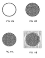
- a second step the contents of the plans of the first step are enlarged to objects with additional pixels.
- Contiguous objects of the plan can be enlarged by up to 24 pixels.
- Figs. 8A and 8B illustrate this.
- Step 3 Filter enlargement for darker colors that do not contain the current color
- C is the next darker base color, so lighter than G, M, R, B and K. C is considered as the current color, so that only M and K are eligible for the cut. Thus, M and K are thus decoded and C "cut to get C '".
- the brightnesses have to be sorted according to their color and their brightness level, where there can be overlaps in the brightness between different planes. For example, this could look like this for three brightness levels per pixel and plane: L K 0 > L Y 0 > L Y 1 > L Y 2 > L C 0 > L G 0 > L M 0 > L C 1 > L G 1 > L R 0 > L M 1 > L B 0 > ... > L K 2
- M is the next darker base color, ie lighter than R, B and K. M is not taken into account as the current color, so only K can be considered for the cut. Thus, K is cut with M "to get M '".
- B is the next darker base color, so only brighter than K. B as the current color is not taken into account, so that for the cut only K is eligible.
- C"' M
- M''' K & M'' .
- G M
- K & G . B ' K & B'''''
- Figs. 9A and 9B illustrate this step using the example of cyan.
- Step 4 Mix with pure original base color
- FIG. 10A and 10B illustrate this.
- steps 1 to 4 are performed, see also Figs. 19A to 19C ,
- FIG. 11A and 11B illustrate this.
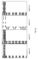
- Fig. 12A shows original picture
- Fig. 12B the color separation for yellow
- Fig. 12C the color separation for cyan
- Fig. 12D the color separation for magenta.
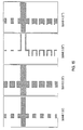
- Fig. 13 shows the individual steps described above for the yellow basic color.
- the image step 1 shows the pure yellow areas from the original
- image step 2 shows the enlarged areas
- image step 3 shows the section with the darker colors
- image step 4 shows the mixed pure yellow color.
- Fig. 14 shows the individual steps for the cyan basic color.
- the image Step 1 shows the pure cyan areas from the original
- Image Step 2 shows the enlarged areas
- Image Step 3 shows the cut with the darker colors
- Image Step 4 shows the pure cyan color mixed to it.
- Fig. 15 shows the individual steps for the green basic color.
- the image step 1 shows the pure green areas from the original, image step 2 shows the enlarged areas, image step 3 shows the section with the darker colors and image step 4 shows the mixed pure green color.
- Fig. 16 shows the individual steps for the magenta basic color.
- the image step 1 shows the pure magenta areas from the original, image step 2 shows the enlarged areas, image step 3 shows the section with the darker colors and image step 4 shows the mixed pure magenta color.
- Fig. 17 shows the individual steps for the red basic color.
- the image step 1 shows the pure red areas from the original, image step 2 shows the enlarged areas, image step 3 shows the section with the darker colors and image step 4 shows the mixed pure red color.
- Fig. 18 shows the individual steps for the blue basic color.
- the image step 1 shows the pure blue areas from the original, image step 2 shows the enlarged areas, image step 3 shows the section with the darker colors and image step 4 shows the mixed pure blue color.
- Fig. 19A shows step 5 for the yellow color separation
- Fig. 19B shows step 5 for the cyan color separation
- Fig. 19C shows step 5 for the magenta color separation.
- HLC data highlight color data
- step 5 is not necessary here.
- the image data describes two colors, eg black K and a highlight color H, then the following can be done:
- step 4 the pure overlay is mixed with the original highlight color.
- H H
- HLC In contrast to the treatment of solid colors or corresponding data, in which the primary colors C, M, Y, K or R, G, B are fixed with their brightnesses, HLC can be colors of different or equal brightness, which from application to application, in particular from printing device to printing device are different. Therefore, in this case, the brightness of the HLC colors is determined and supplied to the trapping system from the outside, on the basis of which it decides which color is trapped to which other color. If both HLC colors have the same brightness (or deviate only slightly from one another in a predefined tolerance range), the colors are no longer trashed against each other, but only against black.
- steps 1-4 of the method are performed for both HLCs, respectively.
- step 4 the pure overlay is mixed with the original HLC.
- H ⁇ 2 ⁇ "'' H ⁇ 2 ⁇ "'
Abstract
Description
Die Erfindung betrifft ein Verfahren, ein Computerprogramm, einen Computer und ein Drucksystem zum Trapping von Bilddaten.The invention relates to a method, a computer program, a computer and a printing system for trapping image data.
Farbige Dokumente oder Dokumententeile, wie z. B. Bilder, Farbgrafiken oder ähnliches, werden meist durch Bilddaten beschrieben, die in Farbauszüge gegliedert sind. Diese Art der Datengliederung entspricht wiederum vielen Druckausgabeverfahren bzw. -geräten, die die Bilddaten in Farbauszügen auf einen Aufzeichnungsträger drucken, z.B. in den Farben Gelb (Y), Magenta (M), Cyan (C) und Schwarz (K) oder in Schwarz und einer oder mehreren sogenannten Highlight Color Farben oder den Océ Custom Tone® Farben.Colored documents or document parts, such as As images, color graphics or the like, are usually described by image data, which are divided into color separations. This type of data structure, in turn, corresponds to many print output methods or apparatus that print the image data in color separations on a record carrier, e.g. in the colors yellow (Y), magenta (M), cyan (C) and black (K) or in black and one or more so-called highlight color colors or the Océ Custom Tone® colors.
Die Anmelderin entwickelt und vertreibt entsprechende digitale elektrografische Drucksysteme. Sie sind z.B. in der Veröffentlichung "
Aus der
Aus der
Aus dem Dokument
Sowohl beim digitalen Druck als auch beim Offset-Druck gibt es das sogenannte Passer-Problem. Dabei handelt es sich darum, dass bei mehreren Druckvorgängen auf einem Blatt Papier aufgrund mechanischer Toleranzen nicht garantiert werden kann, dass die Positionierung des Papiers bei allen Druckvorgängen immer exakt gleich ist. Das Problem tritt auf bei einfarbigem Druck, wenn Vorder- und Rückseite getrennt bedruckt wird oder bei mehrfarbigem Druck auf einer Seite.Both digital printing and offset printing have the so-called passer problem. This is because printing on a sheet of paper can not be guaranteed due to mechanical tolerances, so that the positioning of the paper is always exactly the same for all printing operations. The problem occurs with monochrome printing, if the front and back are printed separately or if multicolored printing on one side.
Beim Vorder- und Rückseitendruck stört dieses Problem, wenn z.B. ein Rahmen je um die Vorder- und Rückseiten gedruckt wird und diese Rahmen nicht exakt aufeinander liegen, was man bemerkt, wenn man die Seite gegen das Licht hält.Front and backside printing interferes with this problem when e.g. a frame is printed around the front and back sides and these frames are not exactly on top of each other, which you notice when you hold the page against the light.
Beim Mehrfarbendruck sind die Farben relativ zueinander versetzt. Solange sich die unterschiedlichen Farben nicht berühren fällt dies nicht weiter auf. Berühren sich die Farben, so werden durch den Versatz die Farben an der Berührungslinie übereinander gedruckt, was zu einer Verfälschung des Farbeindrucks führt, oder es bleibt ein weißer Spalt (Blitzer) an der Berührungslinie.In multicolor printing, the colors are offset relative to each other. As long as the different colors do not touch, this will not be noticeable. If the colors are in contact, the offset causes the colors on the contact line to be printed one above the other, which leads to a falsification of the color impression, or a white slit (flashback) remains at the contact line.
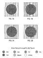
Während die Verfälschung des Farbeindrucks meist noch tolerierbar ist, sind die Blitzer äußerst auffallend, wie durch die Gegenüberstellung exakt positionierter Farben in
Zur Behebung des Blitzer-Problems ist es bekannt, die hellere Farbe zu vergrößern bzw. räumlich zu überfüllen. Damit erhält man zwar eine größere Überdeckung der Farben, aber die Blitzer verschwinden, wie durch die Gegenüberstellung von versetzt positionierten Farben in
Das soeben beschriebene Verfahren, das dieses Problem behebt, hat den Namen "Trapping" (Überfüllung). Trapping wird in unterschiedlichen Produkten am Markt angeboten. Es ist z.B. Bestandteil von Raster Image Prozessoren (RIPs) der Seitenbeschreibungssprache (page description language, PDL) Adobe PostScript® Level 3, der von der Firma Heidelberger Druckmaschinen AG angebotenen Software SuperTrap® oder der Software TrapWise®, die von der Fa. Creo angeboten wird.The procedure just described, which addresses this issue, is called "trapping". Trapping is offered in different products on the market. It is e.g. Part of Raster Image Processors (RIPs) of the page description language (PDL) Adobe PostScript®
Trapping kann auf zwei verschieden Arten durchgeführt werden. Man kann Trapping auf Objektebene behandeln oder auf Bitmapebene.Trapping can be done in two different ways. Trapping can be handled at the object level or at the bitmap level.
Die vorliegende Erfindung betrifft insbesondere die Problematik des Trapping auf BitmapEbene unter Performancegesichtspunkten, die insbesondere bei hohem Druckvolumen und komplexen Vorlagen für einen reibungslosen und effizienten Ablauf eines Druckvorgangs relevant sind.The present invention relates in particular to the problem of trapping at the bitmap level from the point of view of performance, which are relevant in particular for high print volumes and complex originals for a smooth and efficient running of a printing process.
Die Erfindung betrifft auch ein Trapping-Verfahren für sogenannte Highlight Color Bilder oder abgekürzt HLC-Bilder. Derartige Bilder definieren Farben in einem für sie spezifischen Farbraum, bei dem zumindest eine Farbe einen speziellen Farbton umfasst, der in der Regel abseits von denen üblicher Farbstoffe liegt. Dieser Farbton kann z.B. ein anwendungsspezifischer Farbton sein (z.B. für ein farbiges Firmenlogo) und/oder derart angepasst sein, dass er Zugang zu Farbtönen erlaubt, die mit Standard-Druckfarben wie z.B. gelb (Y), magenta (M), cyan (C) und schwarz (K) nicht erreichbar ist. Die Anmelderin vertreibt z.B. derartige Highlight Color Toner für elektrografische Drucker unter dem Handelsnamen Océ Custom Tone®.The invention also relates to a trapping process for so-called highlight color images or abbreviated HLC images. Such images define colors in a color space specific to them, in which at least one color comprises a specific hue, which is usually apart from those of conventional dyes. This hue may e.g. be an application specific color (e.g., for a company logo in color) and / or adapted to allow access to color tones compatible with standard inks, e.g. yellow (Y), magenta (M), cyan (C) and black (K) can not be reached. The applicant distributes e.g. Such highlight color toners for electrographic printers under the trade name Océ Custom Tone®.
Beim Highlight Color-Druck kann auch eine Standardfarbe und eine HLC-Farbe in unterschiedlichen Helligkeitsstufen bzw. Farbsättigungswerten gedruckt werden. In der Regel ist die Standardfarbe schwarz und wird in unterschiedlichen Graustufen gedruckt.With highlight color printing, a standard color and an HLC color can also be printed in different brightness levels or color saturation values. As a rule, the standard color is black and printed in different shades of gray.
Der Highlight-Color-Druck ist kostengünstiger als ein Vollfarbdruck mit vier Grundfarben (sog. Vier-Farbdruck), bei dem durch den Übereinanderdruck von den Grundfarben cyan, magenta, gelb und schwarz verschiedenste Farben erreicht werden können. Bei dem VierFarbdruck ist nachteilig, dass die Leuchtkraft der Farben, die gedruckt werden können, trotz der Farbenvielfalt beschränkt ist. Vor allem in den Bereichen rot, grün und blau kann im Vierfarbdruck-Verfahren oftmals eine von einem Kunden geforderte Leuchtkraft und damit eine kundenspezifische Spezialfarbe häufig nicht erreicht werden.Highlight color printing is more cost-effective than full-color printing with four basic colors (so-called four-color printing), in which the overprinting of the primary colors cyan, magenta, yellow and black different colors can be achieved. In the case of four-color printing, it is disadvantageous that the luminosity of the colors that can be printed is limited despite the variety of colors. Particularly in the areas of red, green and blue, in the four-color printing process often a luminosity demanded by a customer and thus a customer-specific special ink can often not be achieved.
Da oftmals lediglich eine spezielle Farbe gewünscht wird, ist es für derartige Anwendungen wesentlich sinnvoller spezielle Druckfarben zu verwenden, die die gewünschte Farbe aufweisen, wenn sie vollflächig auf das Papier gedruckt werden.Since often only a specific color is desired, it is much more useful for such applications to use special inks that have the desired color when printed over the entire surface of the paper.
Stoßen zwei verschiedene Farben auf einer Seite aneinander, so kann es durch ungenaue Positionierung der verschiedenen Farbauszüge (Passer) zu Überlagerung der Farben kommen, was zu dunklen Rändern führt, oder zu einer Lücke zwischen den Farben, was zu den bereits o.g. weißen Zwischenräumen (Blitzer) führt. Während dunkle Ränder in der Regel noch tolerierbar sind, machen sich Blitzer äußerst störend bemerkbar.If two different colors collide on one side, inaccurate positioning of the different color separations (passer) may lead to superimposition of the colors, resulting in dark edges, or a gap between the colors, which is in addition to the already mentioned. white spaces (speed camera) leads. While dark edges are usually tolerable, speed cameras are extremely disturbing.
Beim Trapping wird das zu einer der beiden beteiligten Farben gehörende Objekt um einen oder mehrere Pixel vergrößert. In der Regel ist eine der beteiligten Farben heller als die andere. Vergrößert man das Objekt mit der dunkleren Farbe, entsteht ein definitiv größeres Objekt, was sich ebenfalls als störend bemerkbar machen kann. Vergrößert man das Objekt der helleren Farbe kommt es nicht zu solch einer optischen Vergrößerung, da das Objekt durch die dunklere Farbe des anderen Objekts überdeckt wird. Aus diesem Grund werden also in der Regel nur die helleren Objekte vergrößert.Trapping increases the object belonging to one of the two colors involved by one or more pixels. As a rule, one of the colors involved is lighter than the other. If you enlarge the object with the darker color, a definitely larger object is created, which can also be disturbing. If the object of the lighter color is enlarged, such an optical magnification does not occur because the object is covered by the darker color of the other object. For this reason, only the brighter objects are usually enlarged.
In der Praxis ist das Problem jedoch wesentlich komplexer. Bei Farben gleicher Helligkeit bzw. Luminanz bleibt das Problem der Wahl, welches Objekt vergrößert werden soll bestehen und gerade in solchen Fällen kommt es meist bei der Überlappung zu Farbveränderungen. Auch ist nicht sichergestellt, dass ein Objekt an jeder Stelle immer die gleiche Farbe hat, sondern es kann auch einen Farbverlauf haben, so dass an einer Stelle das Objekt heller ist, als das Nachbarobjekt und an einer anderen Stelle dunkler, wie in
Das Beispiel der
Will man also auf Objekt-Ebene Trapping durchführen, so kann man keine Standardobjekte mehr verwenden, sondern muss z.B. neue Fonts definieren, oder aber neue geometrische Figuren, wie z.B. wenn aus einem Kreis ein nur in der oberen Hälfte vergrößerter Kreis wird. Damit wird sich dann die Anzahl der verwendeten verschiedenen Objekte gravierend erhöhen, insbesondere, wenn sich weitere Objekte überlagern, wie in
Gerade bei vielen Überlagerungen hängen die Veränderungen der zuerst platzierten Objekte von später platzierten Objekten ab. Damit müssen Objekte ggf. häufig verarbeitet werden.Especially with many overlays, the changes of the first placed objects depend on later placed objects. This may require objects to be processed frequently.
Statt der Veränderung bestehender Objekte lassen sich auch zusätzliche Trapping-Objekte definieren, die gerade den Vergrößerungen an den Konturen der Objekte entsprechen wie in
Da man solche Zusatzobjekte an allen Grenzlinien benötigt, insbesondere auch bei Text, führt dies wieder zu einer enormen Zunahme von Objekten, die zudem noch ggf. wegen komplexer Kurvenführung oder durch Beschreibung von Farb-Verläufen äußerst kompliziert werden können.Since such additional objects are required on all borderlines, especially in the case of text, this again leads to an enormous increase in objects which, in addition, can be extremely complicated due to complex curve routing or by describing color progressions.
Darüber hinaus bedeutet Trapping nicht nur Überfüllung, sondern kann auch Unterfüllung bedeuten. So werden z.B. große schwarze Flächen meist nicht nur auf reines Schwarz abgebildet, sondern zusätzlich mit einem Raster einer andern Farbe z.B. Cyan. Typischerweise geschieht dies beim Colormanagement. Wird dann weißer Text auf die schwarze Fläche gedruckt, können die Cyanpunkte in den weißen Bereich ragen, so dass man solch ein Cyan-Raster (nicht die schwarze Fläche) an den Rändern verkleinern muss. Da das CMM im Drucker nur auf das Profile reagiert und immer entsprechend der tatsächlichen Größe die Fläche mit allen angegebenen Farben füllt, müssen hier zusätzliche weiße Konturenobjekte an den Rändern eingefügt werden, die nur auf die Cyan-Plane und nicht auf die anderen Planes wirken. Ein Trapping-Tool muss also insbesondere die verwendete Profile kennen, auswerten und entsprechende neue Objekte erzeugen. Insgesamt führt ein Trapping auf Objektebene zu einer sehr komplexen Verarbeitung und zu einer unüberschaubaren Vergrößerung der Objektanzahl, teilweise mit neuen Eigenschaften.In addition, trapping not only means overcrowding but can also mean underfilling. For example, large black areas are usually not only mapped to pure black, but also with a grid of another color such as cyan. Typically, this happens with color management. If white text is then printed on the black area, the cyan dots may protrude into the white area, so you have to reduce such a cyan grid (not the black area) at the edges. Since the CMM only responds to the profile in the printer and always fills the area with all specified colors according to the actual size, additional white contour objects must be inserted at the edges, which only affect the cyan plane and not the other planes. In particular, a trapping tool needs to know and evaluate the profiles used and generate corresponding new objects. Overall, trapping at the object level leads to a very complex processing and an unmanageable increase in the number of objects, some with new properties.
Wesentlich einfacher gestaltet sich Trapping auf Bitmapebene. Werden die Objekte nacheinander auf den Hintergrund gemappt, kann man sofort jedes Randpixel des aktuellen Objekts mit dem aktuellen Hintergrund vergleichen und so einfach entscheiden, an welchen Stellen das Objekt und an welcher Stelle der Hintergrund zu vergrößern ist.Trapping is much easier at the bitmap level. If the objects are mapped successively to the background, you can immediately compare each edge pixel of the current object with the current background and thus decide easily, at which points the object and at which point the background is to be enlarged.
Es ist Aufgabe der Erfindung, das Trapping von Bilddaten zu vereinfachen, insbesondere Bitmap-Trapping.It is an object of the invention to simplify the trapping of image data, in particular bitmap trapping.
Die soeben genannte Aufgabe wird durch die in den unabhängigen Ansprüchen angegebene Erfindung gelöst. Vorteilhafte Weiterbildungen der Erfindung sind in den Unteransprüchen angegeben.The object just mentioned is achieved by the invention specified in the independent claims. Advantageous developments of the invention are specified in the subclaims.
Erfindungsgemäß werden in einem Verfahren zum Trapping von Bilddaten die Bilddaten in einem Ausgangsbild bildpunktweise als Farbauszugsdaten, insbesondere als Plane- Bitmaps und/oder als punktweise Grundfarbendaten, bereitgestellt und die Bilddaten verarbeitet.According to the invention, in a method for trapping image data, the image data in an output image are provided pixel by pixel as color separation data, in particular as tarpaulin bitmaps and / or pointwise basic color data, and the image data are processed.
Gemäß einem ersten Aspekt der Erfindung werden um Bildpunkte bzw. Pixel verschiedener Farbauszüge des Ausgangsbildes nach einer Objektvorschrift Objekte mit benachbarten Zusatzbildpunkten erzeugt, wodurch erweiterte Farbauszugsdaten entstehen. Die benachbarten Zusatzbildpunkte eines Farbauszuges werden dann bildpunktweise mit den entsprechenden Bildpunkten des Ausgangsbildes verglichen und zusatzbildpunktweise in Abhängigkeit von den Bilddaten des entsprechenden Bildpunkts des Ausgangsbildes eine Entscheidung getroffen, ob entsprechende Farbauszugsdaten des Ausgangsbild-Bildpunktes zur Erzeugung eines Zielbildpunktwertes um einen dem Zusatzbildpunkt entsprechenden Wert erweitert wird.According to a first aspect of the invention, objects with adjacent additional pixels are generated around pixels or pixels of different color separations of the output image according to an object specification, resulting in extended color separation data. The adjacent additional pixels of a color separation are then pixel-wise compared with the corresponding pixels of the output image and an additional pixel in dependence on the image data of the corresponding pixel of the output image made a decision whether corresponding color separation data of the output image pixel for generating a target pixel value is extended by a value corresponding to the additional pixel ,
Gemäß einem zweiten Aspekt der Erfindung, der unabhängig oder auch in Kombination mit dem ersten Aspekt gesehen werden kann, werden um Bildpunkte verschiedener Farbauszüge des Ausgangsbildes nach einer Objektvorschrift Objekte mit benachbarten Zusatzbildpunkten erzeugt, wodurch erweiterte Farbauszugsdaten entstehen. Die benachbarten Zusatzbildpunkte eines Farbauszuges werden dann bildpunktweise mit den entsprechenden Bildpunkten des Ausgangsbildes verglichen und an der Koordinate des benachbarten Zusatzbildpunktes in Abhängigkeit von den Daten des entsprechenden Ausgangsbild-Bildpunktes eine Entscheidung getroffen, ob der Zusatzbildpunkt in dem vorliegenden Farbauszug gesetzt wird.According to a second aspect of the invention, which can be seen independently or also in combination with the first aspect, objects with adjacent additional pixels are generated around pixels of different color separations of the output image according to an object specification, thereby producing extended color separation data. The Adjacent additional pixels of a color separation are then compared pixel by pixel with the corresponding pixels of the output image and a decision is made at the coordinate of the adjacent additional pixel as a function of the data of the corresponding output image pixel, if the additional pixel is set in the present color separation.
Gemäß einem weiteren Aspekt der Erfindung werden Maßnahmen angegeben, mit denen Highlight Color Daten wirkungsvoll getrappt werden können, insbesondere für Daten mit einer, zwei oder drei Highlight Color Farben, die insbesondere in Verbindung mit schwarz auftreten können.According to a further aspect of the invention, measures are provided with which highlight color data can be effectively trapped, in particular for data with one, two or three highlight color colors, which can occur in particular in combination with black.
Mit der Erfindung ist es insbesondere möglich, auf Basis von Bitmaps ein Trapping durchzuführen. Ein bevorzugtes Ausführungsbeispiel analysiert die Bitmaps dabei derart, dass zusammenhängende Gebiete ermittelbar und als Bildobjekte identifizierbar sind. Demgemäß setzt die Erfindung zwar bei eingehenden Bitmapdaten an, kann aber nach der Erkennung der Bildobjekte Maßnahmen ergreifen, die aus objektbasierten Trappingverfahren bekannt sind.With the invention it is possible, in particular, to perform a trapping on the basis of bitmaps. A preferred embodiment analyzes the bitmaps in such a way that contiguous areas can be determined and identified as image objects. Accordingly, while the invention employs incoming bitmap data, it may take action after recognition of the image objects known from object-based trapping techniques.
Gemäß einem vorteilhaften Ausführungsbeispiel der Erfindung werden zu Anfang Farbauszüge der Farben Gelb (Y), Magenta (M), Cyan (C) und Schwarz (K) bereitgestellt und die Bilddaten der Farben Gelb, Magenta und Cyan in einen Farbraum der Farben Gelb (Y'), Magenta (M'), Cyan (C'), Rot (R'), Grün (G') und Blau (B') transformiert. Die Transformation kann dabei insbesondere nach folgenden Regeln erfolgen: ![]()
![]()
![]()
![]()
![]()
![]()
wobei
die großen Buchstaben jeweils eine Matrix der Bildpunkte der zugehörigen Farbauszüge mit dem entsprechenden Anfangsbuchstaben bezeichnen und K Schwarz bezeichnet.According to an advantageous embodiment of the invention, color separations of the colors yellow (Y), magenta (M), cyan (C) and black (K) are initially provided and the image data of the colors yellow, magenta and cyan are converted into a color space of yellow (Y '), Magenta (M'), cyan (C '), red (R'), green (G ') and blue (B'). The transformation can take place in particular according to the following rules: ![]()
![]()
![]()
![]()
![]()
![]()
in which
the large letters each have a matrix of the pixels of the associated one Designate color separations with the corresponding initial letter and denote K black.
In einer Weiterbildung der Erfindung werden aus den Bildpunkten der Farbauszüge Gelb, Magenta und Cyan Objekte mit benachbarten Zusatzpixeln erzeugt, aber nicht aus den Bildpunkten der Farbe schwarz.In one development of the invention, objects with adjacent additional pixels are generated from the pixels of the color separations yellow, magenta and cyan, but not from the pixels of the color black.
Gemäß einer vorteilhaften Ausführungsform der Erfindung werden die transformierten Bilddaten in einem zweiten Schritt gemäß den Regeln 
verarbeitet, wobei V eine Vorschrift für die Erzeugung der Objekte mit erweiterten Bildpunkten bezeichnet.According to an advantageous embodiment of the invention, the transformed image data in a second step according to the rules
where V denotes a rule for the generation of the objects with extended pixels.
Die Vorschrift V zur Erzeugung der punktweise erweiterten Objekte kann insbesondere nach einer in der internationalen Patentanmeldung
- Abbilden der Bildpunktdatei auf eine Abbildungsdatei, wobei alle Bildpunkte der Abbildungsdatei, die innerhalb eines vorbestimmten Abstandes d zu korrespondierenden Bildpunkten in der Bildpunktdatei liegen, gesetzt werden und
- Bestimmung aller zusammenhängenden Bereiche von in der Abbildungsdatei gesetzten Bildpunkten, wobei ein jeder solcher zusammenhängender Bereich ein Bildobjekt darstellt.
- Die Bildpunktdatei entspricht bei der vorliegenden Erfindung insbesondere der Datei, in der die Pixelwerte einer Plane gespeichert sind.
- Die Bildpunkte in der Bildpunktdatei und in der Abbildungsdatei sind insbesondere in Zeilen und Spalten angeordnet. In der
PCT/EP2004/007000
- Mapping the pixel file to an image file, wherein all pixels of the image file lying within a predetermined distance d to corresponding pixels in the pixel file are set and
- Determining all contiguous areas of pixels set in the map file, each of such contiguous area representing an image object.
- The pixel file in the present invention corresponds in particular to the file in which the pixel values of a tarpaulin are stored.
- The pixels in the pixel file and in the image file are arranged in particular in rows and columns. In the
PCT / EP2004 / 007000
Das in der
- "Das Erweitern der Originalbildpunkte durch Erweiterungsbildpunkte in Spaltenrichtung (
Figur 2a, 2b ,Figur 8a , 8b) wird bei einer Abbildungsdatei, bei welcher die Bildpunkte in Zeilen und Spalten angeordnet sind, vorzugsweise durch eine Oder-Verknüpfung benachbarter Zeilen ausgeführt. Mit einer solchen Oder-Verknüpfung wird ein gesetzter Originalbildpunkt in Spaltenrichtung auf eine benachbarte Zeile abgebildet. Um in Spaltenrichtung in dem durch den Abstand d begrenzten Bereich um ein Originalbildpunkt die entsprechenden Erweiterungsbildpunkte zu setzen, wird die Oder-Verknüpfung auf alle Zeilen ober- und unterhalb dieses Bereiches ausgeführt. - Zur einfachen und schnellen Erweiterung der Originalpunkte durch Erweiterungsbildpunkte in Zeilenrichtung wird vorzugsweise eine Tabelle mit eindimensionalen Bildpunktmustern verwendet. In dieser Tabelle ist jedem Bildpunktmuster ein korrespondierendes Abbildungspunktmuster zugeordnet. Bei der Erweiterungsabbildung werden in Richtung einer Zeile Gruppen von Bildpunkten der Zeile der Bildpunktdatei ausgelesen und mit den Bildpunktmustern verglichen. Das zum übereinstimmenden Bildpunktmuster korrespondierende Abbildungspunktmuster wird in der korrespondierenden Zeile an die korrespondierende Position in der Abbildungsdatei mit einer OderVerknüpfung eingetragen. Hierdurch können ganze Gruppen von Bildpunkten der Bildpunktdatei schnell und einfach auf erweiterte Bildpunkte der Abbildungsdatei abgebildet werden. "
- "Extending Original Pixels with Extension Pixels in Column Direction (
Figure 2a, 2b .FIG. 8a , 8b) is preferably performed by an OR operation of adjacent lines in an image file in which the pixels are arranged in rows and columns. With such an OR operation, a set original pixel is mapped to an adjacent row in the column direction. In order to set the corresponding extension pixels in the column area in the area delimited by the distance d around an original pixel, the OR operation is performed on all lines above and below this area. - For a simple and rapid expansion of the original points by extension pixels in the row direction, a table with one-dimensional pixel patterns is preferably used. In this table, each pixel pattern is assigned a corresponding imaging dot pattern. In the extension mapping, groups of pixels of the line of the pixel file are read out in the direction of a line and compared with the pixel patterns. The matching pixel pattern Corresponding mapping dot patterns are entered in the corresponding line to the corresponding position in the map file with an OR link. As a result, entire groups of pixels of the pixel file can be quickly and easily mapped to extended pixels of the image file. "
Gemäß einem weiteren vorteilhaften Aspekt der vorliegenden Erfindung werden für die Entscheidung, ob entsprechende Farbauszugsdaten des Ausgangsbild-Bildpunktes zur Erzeugung eines Zielbildpunktwertes um einen dem Zusatzbildpunkt entsprechenden Wert erweitert wird, folgende Regeln verwendet: ![]()
![]()
![]()
![]()
![]()
![]()
Weiterhin können bildpunktweise Zwischen-Bilddaten aus den Bilddaten der Ausgangsbildpunkte und der Zusatzbildpunkte ermittelt werden. Die Zwischen-Bilddaten können insbesondere nach folgenden Regeln ermittelt werden: ![]()
![]()
![]()
![]()
![]()
![]()
Die Zielbilddaten werden insbesondere aus den Zwischenbilddaten berechnet und weiterhin insbesondere gemäß den Regeln ![]()
![]()
![]()
![]()
![]()
![]()
Die Bilddaten sind vorzugsweise bildpunktweise binär bzw. als bilevel- bzw. als zweistufige Daten ausgebildet, können aber auch bildpunktweise mehr als zweistufig bzw. als Multilevel-Daten ausgebildet sein.The image data are preferably pixel-wise in binary form or in the form of bilevel or two-stage data, but may also be embodied pixel-by-pixel in more than two-stage or as multilevel data.
Gemäß einem weiteren vorteilhaften Aspekt der Erfindung wurde erkannt, dass das erfindungsgemäße Trapping für eine Dokumentenseite computertechnisch besonders einfach und somit zumindest teilweise automatisch zu bewerkstelligen ist, wenn bereits die komplette Seite aufgerastert ist, insbesondere, wenn das Trapping datentechnisch an Bitmaps durchgeführt wird und damit die Farbauszüge, insbesondere die CMYK-Planes vollständig bekannt sind; denn dann kann für jeden Punkt relativ leicht untersucht werden, ob ein angrenzender Punkt heller oder dunkler ist und entsprechend der Nachbarpunkt eingefärbt wird oder nicht. Das Trapping wird demgemäß insbesondere an Bitmaps durchgeführt, wodurch beispielsweise auch die Datenverarbeitungsgeschwindigkeit hoch ist.According to a further advantageous aspect of the invention, it has been recognized that the document trapping according to the invention is particularly computertechnical for a document page simple and therefore at least partially automatic to accomplish, if already the complete page is rasterized, in particular, if the trapping is carried out data-technically to bitmaps and thus the color separations, in particular the CMYK-plan are completely known; because then it can be relatively easily investigated for each point, whether an adjacent point is lighter or darker and colored according to the neighboring point or not. The trapping is thus carried out in particular to bitmaps, whereby, for example, the data processing speed is high.
Die Erfindung kann insbesondere als Computerprogramm realisiert sein, das bei seinem Laden und Ablaufen auf einem Computer einen Verfahrensablauf nach einem der vorhergehenden Ansprüche bewirkt und/oder oder als Computer, auf dem ein solches Computerprogramm geladen ist. Weiterhin ist die Erfindung als Drucksystem mit einem solchen Computer realisierbar. Der Computer kann dabei insbesondere als Rasterbildprozessor (raster image processor, RIP) ausgebildet sein.The invention can in particular be realized as a computer program which, when loaded and run on a computer, effects a method according to one of the preceding claims and / or as a computer on which such a computer program is loaded. Furthermore, the invention can be realized as a printing system with such a computer. The computer can be designed in particular as a raster image processor (raster image processor, RIP).
Nachfolgend werden Ausführungsbeispiele der Erfindung beschrieben, aus denen weitere Wirkungen und Vorteile der Erfindung deutlich werden. Beigefügte Figuren veranschaulichen die Ausführungsbeispiele.Embodiments of the invention will now be described, from which further effects and advantages of the invention will become apparent. Attached figures illustrate the embodiments.
Wie weiter oben bereits erwähnt läßt sich Trapping grundsätzlich unterschiedlich realisieren. Grundsätzlich ist zu unterscheiden, ob auf Objekt- oder Bitmap-Ebene zu trappen ist.As already mentioned above, trapping can basically be realized differently. It is important to distinguish whether to trap at the object or bitmap level.
Auf Objektebene geschieht das Trapping vor dem Rippen. Es werden die bestehenden Objekte verändert, oder neue Objekte an den Kanten der bestehenden Objekte hinzugefügt. Neue Objekte werden abhängig von den Original-Objekten gefärbt und gemappt.At the object level, trapping happens before ripping. The existing objects are changed, or new objects are added to the edges of the existing objects. New objects are colored and mapped depending on the original objects.
Auf Bitmapebene geschieht das Trapping insbesondere nach dem Rippen und Separieren und ggf. auch nach dem Screenen. Die bestehenden Objekte werden dabei durch den Ripping-Prozess vollständig aufgerastert, so dass nur noch eine einzige Bitmap für eine Seite übrig bleibt. Alle Überdeckungen sind dabei bereits berücksichtigt, so dass auf der Bitmap nur noch die endgültigen Farbübergänge sichtbar sind. Das Trapping muss sich nun um die komplette Bitmap kümmern und dabei Farbübergänge ohne Kenntnis der Objekte herausfinden und entsprechend der Originalfarben die Farben der Bitmap in den separierten Farbauszügen in der Nähe der Farbübergänge verändern. Das Trapping kann aber auch unabhängig von einem Rippen, Separieren oder Screenen an Bitmap-Objekten eines PDL-Datenstroms erfolgen, die in den Datenstrom integriert sind, z.B. an screen shots, Grafiken oder auch Fotos mit scharfen Farbübergängen.At the bitmap level, the trapping is done especially after ripping and separating and possibly also after the screening. The existing objects are rasterized completely by the ripping process, leaving only a single bitmap for a page. All overlaps are already taken into account so that only the final color transitions are visible on the bitmap. The trapping now has to take care of the complete bitmap, finding out color transitions without knowing the objects and changing the colors of the bitmap in the separated color separations in the vicinity of the color transitions according to the original colors. But the trapping can also regardless of ripping, separating or screening on bitmap objects of a PDL data stream that are integrated into the data stream, eg on screen shots, graphics or even photos with sharp color transitions.
-
Objekt-Trapping
- Veränderung der Objekte
- Hinzufügen von Objekten
- Change of objects
- Add objects
-
Bitmap-Trapping
- Nach dem Separieren
- Nach dem Screening
- Multilevel
- Bilevel
- After separation
- After the screening
- multilevel
- bilevel
Beim Trapping von Objekten gibt es einige Vorteile, aber auch Nachteile.When trapping objects, there are some advantages, but also disadvantages.
Grenzen zwei Objekte aneinander, so sind alle Punkte der Grenzlinie bzgl. der Farbunterschiede zu betrachten. Überlappen sich die Objekte opaque, so sind alle Punkte der Randlinie des oberen Objektes bzgl. der Farbunterschiede zum darunter liegenden an dieser Linie zu betrachten. Überlappen sich die Objekte transparent, so hat auch die Transparenz Einfluss auf die sichtbaren Farben und damit auf das Trapping. Somit muss in diesem Fall zur Beurteilung wie das Trapping durchgeführt werden muss, bereits das obere Objekt transparent gemappt werden. Es müssen aber je nur zwei Objekte an ihrem Rand verglichen werden, was bei wenigen Objekten zu wesentlich weniger Aufwand führt, als beim Trapping von Bitmaps. Sind die Objekte noch bekannt, so kann man manuell entscheiden, wie das Trapping in kritischen Fällen durchgeführt werden soll, während bei Bitmaps solch eine individuelle Einstellung nicht möglich ist.If two objects border one another, then all points of the borderline with respect to the color differences must be considered. If the objects overlap opaque, all points of the boundary line of the upper object with respect to the color differences to the underlying one are to be considered at this line. If the objects overlap transparently, the transparency also has an influence on the visible colors and thus on the trapping. Thus, in this case, to assess how trapping must be performed, the upper object must already be mapped transparently. However, only two objects each have to be compared at their edge, which results in considerably less effort with a few objects than with the trapping of bitmaps. If the objects are still known, then one can decide manually how the trapping should be done in critical cases, while with bitmaps such an individual setting is not possible.
Allerdings können Objekte auch Bitmaps sein. Bitmaps werden beim Trapping von Objekten in der Regel nicht behandelt, obwohl auch hier ein Trapping notwendig werden kann. Zum Beispiel kann man alle verwendeten Objekte rippen und dann anstelle der Objekte die generierte Bitmap für das Dokument verwenden. Bei solchen Dokumenten ist das Trapping ebenfalls notwendig. Die Vorgehensweise, solche Dokumente prinzipiell nicht vor dem Trapping zu rippen ist nicht immer anwendbar, da man manchmal keinen Zugriff auf das tatsächliche Original hat (z.B. wenn eine Bitmap aus dem Internet stammt).However, objects can also be bitmaps. Bitmaps are usually not handled when trapping objects, although trapping may be necessary here as well. For example, you can rip all used objects and then use the generated bitmap for the document instead of the objects. Such documents also require trapping. The procedure of not ripping such documents in principle from trapping is not always applicable, since sometimes one does not have access to the actual original (for example, when a bitmap comes from the Internet).
Trapping von Objekten erlaubt eine Bearbeitung abhängig vom Typ eines Objekts. So kann man generell Objekte vom Typ Character (Fonts) anders behandeln, als z.B. Objekte vom Typ Fläche oder Linie.Trapping objects allows editing depending on the type of an object. Thus, one can generally treat objects of the character type (fonts) differently than e.g. Objects of type surface or line.
Beim Trapping von Objekten muss der Algorithmus die verwendete Syntax für die Objektbeschreibung kennen. Damit ist das Trapping stark abhängig von der verwendeten Eingangssprache.When trapping objects, the algorithm must know the syntax used for the object description. Thus, the trapping is highly dependent on the input language used.
Da sich prinzipiell zwei Objekte berühren oder überlagern können, müssen jeweils zwei Objekte auf einer Seite darauf untersucht werden. Die Anzahl der Untersuchungen entspricht dabei der Auswahl von 2 aus n Objekten, wobei n die Anzahl aller Objekte der Seite ist. Dies entspricht einer Anzahl von n * (n-1) / 2 Untersuchungen (quadratischer Aufwand mit n). Besonders bei Text sind die Anzahl der Zeichen sehr groß und liegen meist zwischen 2000 und 4000. Das entspricht 2 bis 8 Millionen Untersuchungen.Since in principle two objects can touch or overlay each other, two objects on one side must be examined. The number of examinations corresponds to the selection of 2 out of n objects, where n is the number of all objects on the page. This corresponds to a number of n * (n-1) / 2 investigations (quadratic effort with n). Especially with text, the number of characters are very large and are usually between 2000 and 4000. This corresponds to 2 to 8 million examinations.
In der Regel überlappen sich Buchstaben nicht, aber man kann sich dessen nicht sicher sein, so dass solche Untersuchungen immer anfallen. Bei Grafiken kommt ein weiteres Problem hinzu. Ein Beispiel zeigt die in
Wegen der einfachen Handhabung bei der Erzeugung von solchen Gebilden in den Tools lassen sich heute schnell größere Objekte aus vielen Einzelobjekten aufbauen (Kopieren und Einfügen).Because of the ease of handling the creation of such entities in the tools, it is now possible to quickly build larger objects from many individual objects (copy and paste).
So führt eine Blumenwiese mit 100 Blumen bereits zu über 48 Millionen Untersuchungen oder bei 1000 Blumen zu mehr als 48 Milliarden Untersuchungen. Benutzt man die Methode des Hinzufügens von Objekten, können aus den 1000 Blumen (98000 Blättern) schnell zusätzliche 48 Milliarden Objekte werden, wenn man nicht die verdeckten Objekte eliminiert (was aber wieder zusätzlichen Aufwand bedeutet). Benutzt man die Methode der Veränderung der bestehenden helleren Objekte, fallen in diesem Fall keine weiteren Objekte an. Dafür besteht hier das Problem im Falle von sich überlagernden Zeichen (Character), dass getrappte halb überdeckte Zeichen in keinem Font vorhanden sind und somit solche Zeichen als Bitmap zu generieren sind oder eine Flut neu zu generierender Fonts erforderlich wird.For example, a flower meadow with 100 flowers already leads to more than 48 million examinations or, with 1,000 flowers, to more than 48 billion examinations. Using the method of adding objects, the 1000 flowers (98,000 leaves) can quickly become an additional 48 billion objects if you do not eliminate the hidden objects (which, however, adds extra effort). If one uses the method of changing the existing brighter objects, in this case no further objects are incurred. There is the problem here in the case of overlapping characters that trapped half-covered characters are not present in any font and thus such characters are to be generated as a bitmap or a flood of newly generated fonts is required.
Beim Trapping von Bitmaps gibt es ebenfalls Vorteile und Nachteile.When trapping bitmaps, there are also advantages and disadvantages.
Da bei Bitmaps die Objekte nicht mehr bekannt sind, lassen sich nicht objektspezifische individuelle Trappingeigenschaften einstellen. Allenfalls kann man Bereiche einer Seite festlegen, die entsprechend anders behandelt werden sollen. Wegen des Aufwands, den ein manuelles Eingreifen in einen automatisierten Ablauf bedeutet, ist aber generell von objektspezifischen individuellen Einstellungen prinzipiell abzuraten.Since the objects are no longer known in bitmaps, it is not possible to set object-specific individual trapping properties. At best, you can specify areas of a page that should be treated differently. Because of the effort, which means a manual intervention in an automated process, but in general of object-specific individual settings in principle to discourage.
Bei der Untersuchung einer Bitmap stellt die Bitmap das Resultat des Mappings der Objekte dar und es gibt kein Übereinander von Objekten mehr. Der Aufwand ist also zunächst einmal unabhängig von der Anzahl der Objekte.When examining a bitmap, the bitmap represents the result of mapping the objects and there is no overlapping of objects. The effort is thus initially independent of the number of objects.
Dafür muss jedes Pixel der Bitmap mit jedem benachbarten Pixel untersucht werden. Die Anzahl der zu betrachtenden Pixel hängt von der Auflösung der Bitmap ab. Bei 600 dpi sind das ca. 34,8 Millionen Pixel was ca. 139,2 Millionen Untersuchungen entspricht. Untersuchungen von Pixel sind in der Regel wesentlich einfacher als Untersuchungen von Objekten. Insbesondere läßt sich durch Ausnutzung der Breite von Registern der Aufwand für die Verarbeitung von Bitmaps erheblich reduzieren. Beim Trapping von Bitmaps werden eingelagerte Bilder automatisch mitgetrappt (Unterdrückung durch Angabe von Bereichen möglich). Bitmaps kommen in wenigen Formaten vor bzw. liegen nach dem Rippen und Separieren im Speicher als separierter Datenstrom vor. Eine Abhängigkeit von der Sprache liegt nicht vor. Benutzt man das Trapping vor dem Screening, so müssen in der Regel vier acht Bit tiefe Planes berücksichtigt werden, was einem Vergleich von 32 Bit entspricht. Hier kann man das Trapping noch abhängig von der Helligkeit der Farbe durchführen. Ein Pixel kann eine von 4 Mrd. Farbkombinationen der Farben C, M, Y und K haben. Benutzt man das Trapping nach dem Screening, so muss noch unterschieden werden, ob es sich um einen Bilevel- oder Multilevel-Drucker handelt. Bei einem Multilevel-Drucker müssen nur noch vier vier Bit tiefe Planes berücksichtigt werden. Das bedeutet eine Aufwandsreduzierung um den Faktor zwei. Hier ist nur noch ein Trapping in Abhängigkeit der Helligkeit der Grundfarben in den Multilevel-Stufen möglich. Ein Pixel kann nur noch eine von 64 K Farbkombinationen der Farben C, M, Y und K haben. Bei einem Bilevel-Drucker müssen nur noch vier ein Bit tiefe Planes berücksichtigt werden. Das bedeutet eine Aufwandsreduzierung um den Faktor acht. Hier ist nur noch ein Trapping in Abhängigkeit der Helligkeit der Grundfarben möglich. Ein Pixel kann nur noch eine von 16 Farbkombinationen der Farben C, M, Y und K haben. Ein Bitmap-Trapping sollte für eine bestimmte Planetiefe bei einer bestimmten Auflösung einen konstanten Aufwand haben (unabhängig von der Anzahl der Objekte und unabhängig vom Inhalt, sprich Farbübergänge).For this, each pixel of the bitmap must be examined with each neighboring pixel. The number of pixels to be considered depends on the resolution of the bitmap. At 600 dpi that is about 34.8 million pixels, which corresponds to about 139.2 million examinations. Pixel research is usually much easier than examining objects. In particular, by utilizing the width of registers, the overhead of processing bitmaps can be significantly reduced. When trapping bitmaps, stored images are automatically included (suppression by specifying areas possible). Bitmaps occur in a few formats or, after ripping and separating, are present in the memory as a separate data stream. There is no dependence on the language. If one uses the trapping before the screening, usually four eight-bit-deep plan must be considered, which corresponds to a comparison of 32 bits. Here you can still perform the trapping depending on the brightness of the color. A pixel can have one of 4 billion color combinations of colors C, M, Y and K. If one uses the trapping after the screening, then one must differentiate whether it concerns a bilevel or multilevel printer. With a multilevel printer, only four four-bit-deep plans need to be considered. This means a cost reduction by a factor of two. Here, only trapping is possible depending on the brightness of the primary colors in the multilevel stages. A pixel can only have one of 64 K color combinations of the colors C, M, Y and K. For a bilevel printer, only four one-bit-deep schedules need to be considered. This means a cost reduction by a factor of eight. Here, only a trapping depending on the brightness of the primary colors is possible. A pixel can only have one of 16 color combinations of the colors C, M, Y and K. Bitmap trapping should have a constant overhead for a given depth of the planet at a given resolution (regardless of the number of objects and regardless of content, that is, color transitions).
Im Bilevel-Fall liegen bei Vollfarb-Daten die Eingangsdaten in vier ein Bit tiefen Planes vor. Für multiple Highlight Color (HLC) Daten läßt sich das Verfahren analog verwenden bzw. erweitern. Jedes Pixel kann nur eine der 24 = 16 Farben (Kombinationen der 4 Grundfarben Cyan, Magenta, Gelb und Schwarz) besitzen. Die Farbe jedes Pixels ist bei einem Ein-Bit-Trapping mit der Farbe jedes der benachbarten acht Pixel zu vergleichen und ggf. die Farbe zu verändern. Führt man solch ein Verfahren direkt wie beschrieben durch, so sind für eine DIN A4 Seite bei 600 dpi 4960 * 7015 = 34,8 Millionen Pixel jeweils mit den acht Nachbarn zu vergleichen. Da jeder Nachbar immer auch mit dem Original verglichen wird, werden alle Vergleiche doppelt durchgeführt, so dass man sich die Hälfte sparen kann indem man nur mit den rechten und den unteren Nachbarn vergleicht. Bei jedem Vergleich ist zu berücksichtigen, dass sowohl das zu vergleichende Pixel, als auch das Nachbar-Pixel eine von 16 Farben besitzen kann, also auf 256 Farbkombinationen zu prüfen sind. Ist bei einem Pixel der Wert in der schwarzen Plane und noch in mindestens einer weiteren Plane gesetzt, so wird das Ergebnis schwarz, so dass wir all diese Fälle genau so behandeln können, als wäre der Wert nur in der schwarzen Plane gesetzt. Damit halbiert sich die Anzahl der Farben auf 8, so dass nur noch 64 Farbkombinationen zu prüfen sind.In the bilevel case, the input data in full-color data is in four one-bit-deep plans. For multiple highlight color (HLC) data, the method can be used or extended analogously. Each pixel can only have one of the 24 = 16 colors (combinations of the 4 primary colors cyan, magenta, yellow and black). The color of each pixel is compared with the color of each of the adjacent eight pixels in a one-bit trapping and, if necessary, to change the color. If such a procedure is carried out directly as described, then for a DIN A4 page at 600 dpi, 4960 * 7015 = 34.8 million pixels can be compared with the eight neighbors. Since each neighbor is always compared to the original, all comparisons are made twice, so that you can save half by comparing only with the right and the lower neighbor. For each comparison, it should be noted that both the pixel to be compared and the neighbor pixel can have one of 16 colors, ie, 256 color combinations. If the pixel is set in the black plane and in at least one other plane, the result will turn black, so that we can handle all these cases as well the value would be set only in the black plane. This halves the number of colors to 8, so that only 64 color combinations are to be checked.
Selbst in solch einem einfachen Bilevel-Fall sind das so viele Operationen, dass eine Durchführung im Drucker nicht sinnvoll erscheint. Aus diesem Grund wird hier ein anderer Ansatz in 5 Schritten beschrieben. Für diesen wird weiter unten anhand der
Zunächst interessieren wir uns für alle Pixel, die reine Grundfarben besitzen. Als Grundfarben bezeichnen wir hier die Farben Cyan, Magenta, Gelb, Rot, Grün und Blau. Schwarz und Weiß betrachten wir hier zunächst nicht als Grundfarbe.First, we are interested in all pixels that have pure primary colors. The basic colors here are the colors cyan, magenta, yellow, red, green and blue. At first, we do not consider black and white as the basic color.
Für Cyan sind dies alle Pixel, für die in der Cyan-Plane ein Bit gesetzt ist, in allen anderen Planes aber kein Bit gesetzt ist. Für Magenta und Gelb gilt das gleiche analog. Für Rot sind dies alle Pixel, für die in der Magenta-Plane und in der Gelb-Plane ein Bit gesetzt ist, in allen anderen Planes aber kein Bit gesetzt ist. Für Grün und Blau gilt das gleiche analog.For cyan, these are all pixels for which one bit is set in the cyan plane but no bit is set in all other planes. For magenta and yellow, the same applies analogously. For red, these are all pixels for which one bit is set in the magenta plane and in the yellow plane, but no bit is set in all other planes. For green and blue, the same applies analogously.
Wir können also aus den bestehenden vier Planes (C,M,Y,K) sechs weitere Planes (C',M',Y',R',G',B') erzeugen mit (∼ bedeutet Negation, aus 0 wird 1 und aus 1 wird 0; | bedeutet ODER bzw. Vereinigung; & bedeutet UND bzw. Schnitt): ![]()
![]()
![]()
![]()
![]()

![]()
![]()
![]()
![]()
![]()
In diesen Planes kommen nur noch die reinen Grundfarben und keine Mischfarben vor. Jeder Bildpunkt bzw. jedes Pixel, das nicht nur schwarz (bzw. weiß) ist, wird demnach in diesen sechs Grundfarben (Planes) dargestellt. Die Pixeldaten erfahren eine entsprechende Bildtransformation.
In einem zweiten Schritt werden die Inhalte der Planes des ersten Schrittes zu Objekten mit Zusatzbildpunkten vergrößert. Dazu bedienen wir uns des Algorithmus bzw. des Verfahrens, die in der 
Diese Vergrößerung wurde ohne Berücksichtigung der Nachbarpixel durchgeführt. Wir interessieren uns zunächst nur für die Pixel, die tatsächlich neu hinzukommen. Dies sind genau die Pixel, welche nicht die aktuelle Grundfarbe enthalten und die sich mit dunkleren Farben überlappen. Dazu müssen wir alle Grundfarben in der Reihenfolge ihrer Luminanz ordnen: 
Y ist die hellste Grundfarbe, also heller als C, G, M, R, B und K. Wegen R = M+Y, G = C+Y und B = M+C sind R, G und B bereits in den C, M, und Y Planes enthalten, d.h. ein Bildpunkt der Farben rot, grün oder blau ist jeweils vollständig mit Koordinaten in den Planes C, M und Y darstellbar. Y als aktuelle Farbe wird nicht berücksichtigt, weil nur die Vergrößerungen gegenüber dunkleren Farben betrachtet werden, so dass für den Schnitt nur noch C, M und K in Frage kommen. Damit werden also C, M und K verodert und mit Y" geschnitten um Y'" zu erhalten, wobei W=weiß und K=schwarz sind.Y is the brightest base color, ie lighter than C, G, M, R, B and K. Because of R = M + Y, G = C + Y and B = M + C, R, G and B are already in the C, M, and Y planes included, ie a pixel of the colors red, green or blue can be represented completely with coordinates in the plans C, M and Y respectively. Y as current color is not taken into account, because only the enlargements are compared with darker colors, so that only C, M and K are considered for the cut. Thus, C, M and K are thus ORed and Y "cut to get Y '", where W = white and K = black.
C ist die nächst dunklere Grundfarbe, also heller als G, M, R, B und K. C als aktuelle Farbe wird nicht berücksichtigt, so dass für den Schnitt nur noch M und K in Frage kommen. Damit werden also M und K verodert und mit C" geschnitten um C'" zu erhalten.C is the next darker base color, so lighter than G, M, R, B and K. C is considered as the current color, so that only M and K are eligible for the cut. Thus, M and K are thus decoded and C "cut to get C '".
Im multilevel-Fall (mehr als 2 Helligkeitsstufen pro Bildpunkt in einer Plane) müssen die Helligkeiten entsprechend ihrer Farbe und ihrer Helligkeitsstufe sortiert werden, wobei es in der Helligkeit Überschneidungen zwischen verschiedenen Planes geben kann. Dies könnte für drei Helligkeitsstufen pro Bildpunkt und Plane z.B. so aussehen: ![]()
![]()
Zurück zum bilevel-Fall: G ist die nächst dunklere Grundfarbe, also heller als M, R, B und K. G als aktuelle Farbe wird nicht berücksichtigt, so dass wegen G = C+Y für den Schnitt nur noch M und K in Frage kommen. Damit werden also M und K verodert und mit G" geschnitten um G"' zu erhalten.Back to the bilevel case: G is the next darker base color, so lighter than M, R, B and K. G as the current color is not taken into account, so that because of G = C + Y for the cut only M and K in question come. Thus, M and K are thus ORed and cut with G "to get G" '.
M ist die nächst dunklere Grundfarbe, also heller als R, B und K. M als aktuelle Farbe wird nicht berücksichtigt, so dass für den Schnitt nur noch K in Frage kommen. Damit wird also K mit M" geschnitten, um M'" zu erhalten.M is the next darker base color, ie lighter than R, B and K. M is not taken into account as the current color, so only K can be considered for the cut. Thus, K is cut with M "to get M '".
R ist die nächst dunklere Grundfarbe, also heller als B und K. R als aktuelle Farbe wird nicht berücksichtigt, so dass für den Schnitt nur noch B = M+C und K in Frage kommen. Damit werden also M und C geschnitten, mit K verodert und mit R" geschnitten, um R'" zu erhalten.R is the next darker base color, ie brighter than B and K. R is considered as the current color, so that only B = M + C and K are eligible for the cut. Thus M and C are cut, coded K, and R "cut to get R '".
B ist die nächst dunklere Grundfarbe, also nur noch heller als K. B als aktuelle Farbe wird nicht berücksichtigt, so dass für den Schnitt nur noch K in Frage kommt. Damit wird K mit B" geschnitten, um B'" zu erhalten. ![]()

![]()
Es bleibt noch, zu den R"'-, G"'-,B"'-, C'"-, M"'- und Y"'-Planes jeweils die Original-Grundfarbe dazu zu mischen: 
![]()
![]()
Für jede Grundfarbe werden die Schritte 1 bis 4 durchgeführt, siehe auch
Zu diesen Planes müssen nun die ursprünglichen Werte der Mischfarben dazu gemischt werden. ![]()
![]()
Es wird ein Bild untersucht, in dem die Grundfarben in der Reihenfolge ihrer Luminanz Y, C, G, M, R, B, K in senkrechten und waagerechten Streifen (von oben nach unten bzw. von links nach rechts) vorkommen, so dass alle möglichen Farbübergänge zweimal auftreten.
Werden diese drei Farbauszüge übereinander gelegt und noch mit der schwarzen Plane gedruckt, so überdecken sich einige Farben, die dann als Mischfarben meist schwarz auftreten. In der
Die schwarze Plane wurde bei den beschriebenen Beispielen nicht geändert. Natürlich kann man in einem abgewandelten Verfahren soweit möglich zunächst CMYK in CMY (+ΔK) umrechnen und danach wieder zu CMYK zurückkehren.The black tarp was not changed in the examples described. Of course you can in a modified method as far as possible first convert CMYK into CMY (+ ΔK) and then return to CMYK again.
Die Operationen wurden der Verständlichkeit halber einzeln aufgeführt. Für eine Beschleunigung lassen sich aber Schritte zusammenfassen.The operations were listed individually for the sake of clarity. For an acceleration, however, steps can be summarized.
Oben wurde ein pixelbasiertes Trappingverfahren für Vollfarb-Bildpunktdaten (z.B. YMCK) beschrieben, die für jede Farbe jeweils in 2 Bits codiert sind (Bileveldaten). Das beschriebene Verfahren eignet sich aber auch für ein entsprechendes pixelbasiertes Trapping an sogenannten Highlight Color daten (HLC Daten) . Nachfolgend soll das Verfahren für HLC-Daten näher beschrieben werden.Above, a pixel-based trapping method has been described for full color pixel data (e.g., YMCK) encoded in 2 bits for each color (bilevel data). However, the described method is also suitable for a corresponding pixel-based trapping on so-called highlight color data (HLC data). The procedure for HLC data will be described in more detail below.
Für das Bitmap-Trapping bei HLC Daten können wie beim Trapping für Vollfarbdaten grundsätzlich fünf Schritte vorgesehen werden:
Schritt 1 Filtern der reinen GrundfarbenSchritt 2 VergrößerungSchritt 3 Filtere Vergrößerung bei dunkleren Farben, die nicht die aktuelle Farbe enthaltenSchritt 4 Mischen mit reinen Original-Grundfarbe- Schritt 5 Mischen mit Mischfarben
-
Step 1 Filter the pure primary colors -
Step 2 Enlargement -
Step 3 Filter enlargement for darker colors that do not contain the current color -
Step 4 Mix with pure original base color - Step 5 Mix with mixed colors
Bei HLC-Daten ist es aber möglich, Mischfarben (z.B. R = M | Y) nicht zu berücksichtigen, so dass hier der Schritt 5 nicht notwendig ist.However, in HLC data, it is possible to disregard mixed colors (e.g., R = M | Y), so step 5 is not necessary here.
Wenn die Bilddaten zwei Farben beschreiben, z.B. schwarz K und eine Highlight Color Farbe H, so kann wie folgt vorgegangen werden:If the image data describes two colors, eg black K and a highlight color H, then the following can be done:
Im Schritt 1 wird aus den zwei Planes (H,K) eine weitere Plane (H ') erzeugt, mit: 
(∼ bedeutet Negation, aus 0 wird 1 und aus 1 wird 0)In
(~ Means negation, 0 becomes 1 and 1 becomes 0)
In Schritt 2 wird der Inhalt dieser Plane vergrößert. Dazu kann wiederum das in der 
In Schritt 3 wird die dunklere Farbe, hier also schwarz berücksichtigt. Es wird die reine Überdeckung ermittelt 
In Schritt 4 wird die reine Überdeckung mit der originalen Highlight Farbe gemischt. 
Schritt 3 und 4 lassen sich wiederum als einen Schritt zu H"" = (K & H") | H zusammenfassen.
Im Unterschied zur Behandlung von Vollfarben bzw. entsprechenden Daten, bei denen die Grundfarben C, M, Y, K bzw. R, G, B mit ihren Helligkeiten fest bestimmt sind, kann es sich bei HLC um Farben unterschiedlicher oder gleicher Helligkeiten handeln, die von Anwenung zu Anwendung, insbesondere von Druckgerät zu Druckgerät unterschiedlich sind. Deshalb wird in diesem Fall die Helligkeit der HLC-Farben bestimmt und dem Trapping-System von außen zugeführt, auf deren Basis es entscheidet, welche Farbe gegenüber welcher anderen Farbe getrappt werden. Haben beide HLC-Farben die gleiche Helligkeit (oder weichen in einem vordefinierten Toleranzbereich nur wenig von einander ab) so werden die Farben nicht mehr gegeneinander sondern jeweils nur gegen schwarz getrappt.In contrast to the treatment of solid colors or corresponding data, in which the primary colors C, M, Y, K or R, G, B are fixed with their brightnesses, HLC can be colors of different or equal brightness, which from application to application, in particular from printing device to printing device are different. Therefore, in this case, the brightness of the HLC colors is determined and supplied to the trapping system from the outside, on the basis of which it decides which color is trapped to which other color. If both HLC colors have the same brightness (or deviate only slightly from one another in a predefined tolerance range), the colors are no longer trashed against each other, but only against black.
Wenn die beiden HLC-Farben mit H1 und H2 bezeichnet werden, dann sind zwei Fälle zu unterscheiden:
- 1. H1 □ H2. (Helligkeit von H1 ist gleich oder ungefähr gleich der Helligkeit von H2)
- 2. H1 < H2. (Helligkeit von H1 ist kleiner als die Helligkeit von H2)
- 1. H1 □ H2. (Brightness of H1 is equal or approximately equal to the brightness of H2)
- 2. H1 <H2. (Brightness of H1 is less than the brightness of H2)
Im Fall 1 werden die Schritte 1-4 des Verfahrens jeweils für beide HLC durchgeführt.In
Im Fall 2 wird nur H1 gegenüber K getrappt und H2 gegenüber K und H1.In
Für das Tappen von H1 nur gegenüber K werden wieder die o.g. Schritte 1-4 des Verfahrens durchgeführt. Für das Tappen von H2 gegenüber K und H1 werden die Schritte 1-5 im folgenden beschrieben:For the tapping of H1 only opposite K the o.g. Steps 1-4 of the process performed. For tapping H2 versus K and H1, steps 1-5 are described below:
Im Schritt 1 wird aus den drei Planes (H1, H2,K) eine weitere Plane (H2 ') erzeugt (∼ bedeutet Negation, aus 0 wird 1 und aus 1 wird 0): 
In Schritt 2 wird der Inhalt dieser Plane vergrößert. Dazu kann wiederum das in der 
In Schritt 3 wird die dunklere Farbe, also schwarz berücksichtigt. Es wird die reine Überdeckung ermittelt 
In Schritt 4 wird die reine Überdeckung mit der originalen HLC gemischt. 
Die Schritte 3 und 4 lassen sich wiederum zu H2"" = ((K | H1) & H2") | H2 zusammenfassen.
Bei filigranen Objekten wie z.B. feinen Linien oder kleinen Buchstaben auf Rastern können, wenn die Objektmaße wie z.B. Liniendicken kleiner werden als die benötigte Trappweite, beim Trapping "Schattenbilder" entstehen. Bei feinen Linien erkennt man dann z.B. neben der originalen Linie eine getrappte Linie. Diese Situation sollte bei Druckgeräten mit einer geringen Trappweite bzw. Registerungenauigkeit, z.B. von maximal 3 Pixel Trappweite, nicht erscheinen oder keinen erheblichen visuellen Effekt haben. Bei Druckgeräten mit größerer Trapweite wirken sich diese Effekte u.U. in nicht akzeptabler Weise aus. Das Druckbild kann dabei durch das Trappen gegenüber einem ohne Trapping erzeugten Druckbild verschlechtert werden. Um ein günstiges Trapping auch für solche Druckgeräte nutzen zu können wird vorgeschlagen, das Trapping nur bei "großen" Objekten durchzuführen und bei kleinen Objekten das Original zu belassen.For filigree objects such as fine lines or small letters on grids can, if the object dimensions such. Line widths are smaller than the required Trappweite, trapping "silhouettes" arise. For fine lines, one then recognizes e.g. next to the original line a traced line. This situation should be addressed with low trapping devices or register inaccuracies, e.g. of a maximum of 3 pixels trapping, do not appear or have any significant visual effect. For printing devices with a larger track width, these effects may be affected. in an unacceptable way. The printed image can be degraded by busting against a printed image generated without trapping. In order to be able to use a favorable trapping also for such pressure devices it is suggested to carry out the trapping only with "large" objects and to leave the original with small objects.
Bei einem reinen Bitmap-Trapping ist an sich eine Objekterkennung oder eine objektabhängige Bearbeitung nicht vorgesehen. Mit dem in der
Claims (25)
- A method for trapping of image data, wherein- the image data are provided in an initial image image point-wise as colour separation data in initial colours (Y, M, C), comprising the following steps:- in a first step the initial image data are transformed to first transformed image data (Y', M', C', R', G', B') such that each initial image point that is not only black or white is presented in basic colours, wherein the basic colours comprise the initial colours (Y, M, C) and further basic colours (R, G, B) that are determined from the initial colours by means of logical AND-, OR- and/or NEGATIONoperations and wherein each image point of the first transformed image data (Y', M', C', R', G', B') is assigned at most one basic colour (Y, M, C, R, G);- in a second step the first transformed image data (Y', M', C', R', G', B') are transformed according to the basic colours to second transformed image data (Y", M", C", R", G", B") such that coherent objects of one basic colour are enlarged according to an enlargement rule;- in a third step the second transformed image data (Y", M", C", R", G", B") are filtered to third transformed image data (Y"', M"', C"', R"', G"', B''') such that the image date of a basic colour to an image point is only accepted if the image point also contains a darker basic colour;- in a fourth step the third transformed image data (Y"', M"', C"', R"', G"', B"') are transformed to fourth transformed image data (Y"", M"", C"", R"", G" ", B"") such that the transformed first image data (Y', M', C', R', G', B') of one basic colour are merged image point-wise to the third transformed image data (Y"', M"', C"', R"', G"', B''').
- The method according to claim 1, wherein in a fifth step the fourth transformed image data (Y"", M"", C"", R"", G"", B"") are transformed image point-wise to target image data of the initial colours (Y""', M""', C""') such that the fourth transformed image data of the further basic colours (R"", G"", B"") are merged to the fourth transformed image data of the initial colours (Y"", M"", C'''').
- The method according to claim 1 or 2, wherein in the first step initial image data of the colours yellow, magenta, cyan and black are transformed to first transformed image data of a colour space with the colours yellow, magenta, cyan, red, green and blue.
- The method according to claim 3, wherein the first transformation occurs according to the rules:


wherein- the capital letters C, Y, M, R, G and B each designate a matrix of the initial image data of the colour separations cyan, yellow, magenta, red, green and blue;- K designates a matrix of the image points of the colour separation black;- C', Y', M', R', G' and B' designate the matrices formed by the first step of the first transformed image data obtained from the respective arithmetic operations associated with the colour separations;- the operation "|" designates an "OR"-operation, the operation "&" designates and "AND"-operation and the operation "-" designates a NEGATION-operation. - The method according to claim 4, wherein the image data are processed in the second step for enlarging the objects according to the rules:


wherein V designates the rule for the generation of the objects with extended image points, and C", Y", M", R", G" and B" designate matrices for the second transformed image data obtained from the second step and from the respective arithmetic operations associated with the colour separations. - The method according to claim 5, wherein the associated image points of the image data of a colour separation are stored in an image point file, and in a third step for forming the objects the image point file is mapped to a mapping file, wherein all image points of the mapping file that lie within a predetermined distance (d) of corresponding image points in the image point file are placed.
- The method according to claim 6, wherein the image points in the image point file and in the mapping file are arranged in rows and columns and a table with one-dimensional image point patterns is provided, wherein a corresponding mapping point pattern is assigned to each image point pattern, wherein groups of image points of one row of the image point file are compared with the image point patterns when mapping in the direction of the rows, and wherein the mapping point pattern corresponding to the coinciding image point pattern is entered into the corresponding row at the corresponding position of the mapping file with an OR-link.
- The method according to claim 6 or 7, wherein the distance (d) is automatically varied dependent on a font size and/or a rastering and/or a granularity.
- The method according to claim 5, wherein in the third step the following rules are used for deciding as to whether corresponding colour separation data of the initial image image point are extended by a value corresponding to the additional image point to generate a target image point value:


wherein C"', Y"', M"', R"', G'" and B"' designate matrices for the third transformed image data obtained from the third step and from the corresponding arithmetic operation associated with the colour separations. - The method according to claim 9, wherein in the fourth step the following rules are used:


wherein C"" Y"", M'''', R"", G"" and B"" are matrices for the fourth transformed image data obtained from the fourth step and from the respective arithmetic operations associated with the colour separations. - The method according to claim 2, wherein in the fifth step the following rules are used:


wherein C""', Y""', M'"", R""', G""' and B""' are matrices for the fifth transformed image data obtained from the fifth step and from the respective arithmetic operations associated with the colour separations. - The method according to one of the preceding claims, wherein the image data are two-stage image point-wise.
- The method according to one of claims 1 to 11, wherein the image data are more than two-stage image point-wise.
- The method according to one of the preceding claims, wherein the trapping is implemented on bitmaps.
- The method according to one of the preceding claims, wherein the trapping occurs independent of a ripping, separation or screening of bitmap objects of a PDL data stream that are integrated into the data stream.
- The method according to claim 15, wherein the trapping occurs on a screen shot image, a graphic or a photo.
- The method according to one of claims 1, 6, 7, 8, 12, 13, 14, 15 or 16, wherein the initial image data only comprise data regarding two colours (H, K) and a further colour separation (H') from the data of the two colour separation data (H, K) image point-wise according to the rule

is formed, and wherein from the data of the further colour separation coherent image objects are determined and a further separation is formed in which these image objects are enlarged according to the rule

overlaying the separation so generated with the data of the original colour separations according to the rule
wherein the capital letters H, K each designate a matrix of the initial image data of the colour separations of both colours;
H', K' designate the matrices formed by the first step of the first transformed image data obtained from the respective arithmetic operations associated with the colour separations;
H", K" designate the matrices formed by the second step of the second transformed image data obtained from the respective arithmetic operations associated with the colour separations;
H"', K"' designate the matrices formed by the third step of the third transformed image data obtained from the respective arithmetic operations associated with the colour separations;
H"", K'''' designate the matrices formed by the fourth step of the fourth transformed image data obtained from the respective arithmetic operations associated with the colour separations; and
V designates the enlargement rule. - The method according to one of claims 1, 6, 7, 8, 12, 13, 14, 15 or 16, wherein the initial image data contain only data regarding two highlight colour colours (H1, H2) and regarding black (K), and wherein various trapping rules are used dependent on a brightness difference between the two highlight colour colours.
- The method according to claim 18, wherein the method according to claim 17 is executed in the case of substantially identical brightnesses of the two highlight colour colours.
- The method according to claim 19, wherein in the event of significantly different brightnesses of the highlight colour colours the data of the darker colour (H1) are trapped only against the data of the black colour and the data of the brighter highlight colour colour (H2) are trapped against the data of the two other colours (H1, K).
- The method according to one of the preceding claims, wherein it is determined or established whether filigree image objects are contained in the image data, and wherein an image separation is formed in which image objects are initially shrunk according to a rule (V) and then are enlarged again such that image objects the measurements of which under-run a lower limit at least in one direction are eliminated from the image separation in the course of the reduction before further trapping method steps are applied.
- The method according to one of the preceding claims, wherein related areas from the image data based on bitmaps are determined and classified as objects and then trapping measures are used object-wise.
- Computer program that, when loaded and run on a computer, causes a process according to one of the preceding claims.
- Computer on which a computer program according to claim 23 is loaded.
- Printing system with a computer according to claim 24.
Applications Claiming Priority (2)
| Application Number | Priority Date | Filing Date | Title |
|---|---|---|---|
| DE102004062841A DE102004062841A1 (en) | 2004-12-27 | 2004-12-27 | Method, computer program, computer and printing systems for trapping image data |
| PCT/EP2005/057147 WO2006069980A1 (en) | 2004-12-27 | 2005-12-23 | Method, computer program, computer and printing system for trapping image data |
Publications (2)
| Publication Number | Publication Date |
|---|---|
| EP1842361A1 EP1842361A1 (en) | 2007-10-10 |
| EP1842361B1 true EP1842361B1 (en) | 2012-08-15 |
Family
ID=36084154
Family Applications (1)
| Application Number | Title | Priority Date | Filing Date |
|---|---|---|---|
| EP05825216A Expired - Fee Related EP1842361B1 (en) | 2004-12-27 | 2005-12-23 | Method, computer program, computer and printing system for trapping image data |
Country Status (4)
| Country | Link |
|---|---|
| US (1) | US7856140B2 (en) |
| EP (1) | EP1842361B1 (en) |
| DE (1) | DE102004062841A1 (en) |
| WO (1) | WO2006069980A1 (en) |
Families Citing this family (8)
| Publication number | Priority date | Publication date | Assignee | Title |
|---|---|---|---|---|
| CN100576238C (en) * | 2006-09-30 | 2009-12-30 | 北京大学 | A kind of grating image processing method and device |
| DE102006055624B4 (en) * | 2006-11-24 | 2008-12-11 | OCé PRINTING SYSTEMS GMBH | Method, computer program and printing system for trapping print data with a plurality of objects |
| DE102006055625B4 (en) * | 2006-11-24 | 2008-12-04 | OCé PRINTING SYSTEMS GMBH | Method, computer program and printing system for trapping print data with a plurality of objects |
| DE102006055587B4 (en) * | 2006-11-24 | 2008-12-11 | OCé PRINTING SYSTEMS GMBH | Method, computer program and printing system for trapping print data with a plurality of objects |
| DE102006055626B4 (en) * | 2006-11-24 | 2008-12-04 | OCé PRINTING SYSTEMS GMBH | Method, computer program and printing system for trapping print data with a plurality of objects |
| DE102008007339B4 (en) | 2008-02-04 | 2011-04-07 | OCé PRINTING SYSTEMS GMBH | Method and device for generating print data |
| US8004718B2 (en) * | 2009-01-12 | 2011-08-23 | Xerox Corporation | Post RIP trapping |
| WO2017208108A1 (en) * | 2016-05-30 | 2017-12-07 | Liefferink Hauke Maritz | Method of printing full colour images |
Family Cites Families (15)
| Publication number | Priority date | Publication date | Assignee | Title |
|---|---|---|---|---|
| JPH01170169A (en) | 1987-12-25 | 1989-07-05 | Dainippon Screen Mfg Co Ltd | Method for processing image graphic correction for multicolor printing |
| US5131058A (en) * | 1990-08-24 | 1992-07-14 | Eastman Kodak Company | Method for obtaining output-adjusted color separations |
| JPH0817445B2 (en) * | 1990-11-06 | 1996-02-21 | 大日本スクリーン製造株式会社 | Image processing method |
| US5613046A (en) * | 1993-03-31 | 1997-03-18 | Miles Inc. | Method and apparatus for correcting for plate misregistration in color printing |
| US5581667A (en) * | 1994-12-23 | 1996-12-03 | Xerox Corporation | Electronic trapping system for digitized text and images |
| CA2210552C (en) * | 1996-09-27 | 2001-05-15 | Xerox Corporation | System and method for mitigating the visual effects of halo |
| DE59702478D1 (en) * | 1997-03-03 | 2000-11-16 | Oce Printing Systems Gmbh | PRINTING AND COPYING MACHINE FOR PERFORMANCE-ADJUSTED, MONOCHROME AND / OR COLORED, SINGLE OR DOUBLE-SIDED PRINTING OF A RECORDING MEDIUM |
| US6236754B1 (en) * | 1998-01-08 | 2001-05-22 | Xerox Corporation | Image modification to reduce susceptibility to misregistration |
| JP2000196906A (en) * | 1998-10-22 | 2000-07-14 | Xerox Corp | System and method for printing |
| JP4234281B2 (en) * | 1998-10-22 | 2009-03-04 | ゼロックス コーポレイション | Printing system |
| DE19912511A1 (en) * | 1999-03-19 | 2000-09-21 | Heidelberger Druckmasch Ag | Process for creating trapping contours in a printed page |
| NL1012708C2 (en) * | 1999-07-26 | 2001-01-29 | Ocu Technologies B V | Printing digital color images with locally adapted halftoning. |
| US6509903B1 (en) * | 1999-10-06 | 2003-01-21 | Creoscitex Corporation Ltd. | System and method for recording an image |
| US6992798B2 (en) * | 2000-03-09 | 2006-01-31 | Agfa-Bevaert N.V. | Apparatus, product, and method of trapping using a distance buffer |
| DE10329339B4 (en) | 2003-06-30 | 2007-04-26 | OCé PRINTING SYSTEMS GMBH | Method and device for processing a pixel file |
-
2004
- 2004-12-27 DE DE102004062841A patent/DE102004062841A1/en not_active Withdrawn
-
2005
- 2005-12-23 US US11/719,156 patent/US7856140B2/en not_active Expired - Fee Related
- 2005-12-23 EP EP05825216A patent/EP1842361B1/en not_active Expired - Fee Related
- 2005-12-23 WO PCT/EP2005/057147 patent/WO2006069980A1/en active Application Filing
Also Published As
| Publication number | Publication date |
|---|---|
| US7856140B2 (en) | 2010-12-21 |
| US20090141972A1 (en) | 2009-06-04 |
| EP1842361A1 (en) | 2007-10-10 |
| WO2006069980A1 (en) | 2006-07-06 |
| DE102004062841A1 (en) | 2006-07-13 |
Similar Documents
| Publication | Publication Date | Title |
|---|---|---|
| DE69910631T2 (en) | Image adjustment to reduce sensitivity to incorrect registration | |
| DE69935120T2 (en) | Automatic improvement of print quality based on size, shape, orientation and color of textures | |
| EP1842361B1 (en) | Method, computer program, computer and printing system for trapping image data | |
| DE60009644T2 (en) | Color conversion using local information | |
| DE69822545T2 (en) | Image enhancement using surface interpolation | |
| DE60035401T2 (en) | Gradient-based improvement of color separation areas with the help of patterned areas | |
| DE10204751B4 (en) | Method for converting a linework data format into the format of a page description language | |
| EP1166548A1 (en) | Method for producing trapping contours in a printed page | |
| EP0764310A1 (en) | Method of generating a contonic map | |
| EP2092730B1 (en) | Method, computer program and print system for trapping print data | |
| EP1002421B1 (en) | Device and method for preparing documents for multicolour reproduction | |
| DE102006055624B4 (en) | Method, computer program and printing system for trapping print data with a plurality of objects | |
| DE60033479T2 (en) | Image generation system and method | |
| DE69834227T2 (en) | Detection and correction of color gaps | |
| DE60306324T2 (en) | System and method for processing a multicolor image | |
| DE102006055625B4 (en) | Method, computer program and printing system for trapping print data with a plurality of objects | |
| DE102006047436B4 (en) | Method and system for the automatic preparation of print data for a printing process | |
| EP0978097B1 (en) | Method for modifying the size of line elements | |
| DE10008286C1 (en) | Method for printing an HLC image (Highlight Color Image) so that image printing can be limited to selection of the appropriate half-tone printing reference pattern, which is quicker and easier than existing methods | |
| DE102006055626B4 (en) | Method, computer program and printing system for trapping print data with a plurality of objects | |
| WO1998043207A1 (en) | Image processing method and circuit arrangement for changing image resolution | |
| DE102008007339B4 (en) | Method and device for generating print data | |
| DE4402723A1 (en) | Half-tone image reproduction method e.g. for DTP | |
| EP1223743B1 (en) | Method for screen adaptive copying retouching | |
| DE10305046B4 (en) | Method of generating a raster bitmap proof |
Legal Events
| Date | Code | Title | Description |
|---|---|---|---|
| PUAI | Public reference made under article 153(3) epc to a published international application that has entered the european phase |
Free format text: ORIGINAL CODE: 0009012 |
|
| 17P | Request for examination filed |
Effective date: 20070727 |
|
| AK | Designated contracting states |
Kind code of ref document: A1 Designated state(s): DE FR GB |
|
| DAX | Request for extension of the european patent (deleted) | ||
| RBV | Designated contracting states (corrected) |
Designated state(s): DE FR GB |
|
| 17Q | First examination report despatched |
Effective date: 20080603 |
|
| GRAP | Despatch of communication of intention to grant a patent |
Free format text: ORIGINAL CODE: EPIDOSNIGR1 |
|
| GRAS | Grant fee paid |
Free format text: ORIGINAL CODE: EPIDOSNIGR3 |
|
| GRAA | (expected) grant |
Free format text: ORIGINAL CODE: 0009210 |
|
| AK | Designated contracting states |
Kind code of ref document: B1 Designated state(s): DE FR GB |
|
| REG | Reference to a national code |
Ref country code: GB Ref legal event code: FG4D Free format text: NOT ENGLISH |
|
| REG | Reference to a national code |
Ref country code: DE Ref legal event code: R096 Ref document number: 502005013020 Country of ref document: DE Effective date: 20121011 |
|
| PLBE | No opposition filed within time limit |
Free format text: ORIGINAL CODE: 0009261 |
|
| STAA | Information on the status of an ep patent application or granted ep patent |
Free format text: STATUS: NO OPPOSITION FILED WITHIN TIME LIMIT |
|
| 26N | No opposition filed |
Effective date: 20130516 |
|
| REG | Reference to a national code |
Ref country code: DE Ref legal event code: R082 Ref document number: 502005013020 Country of ref document: DE Representative=s name: PATENTANWAELTE SCHAUMBURG, THOENES, THURN, LAN, DE |
|
| GBPC | Gb: european patent ceased through non-payment of renewal fee |
Effective date: 20121223 |
|
| REG | Reference to a national code |
Ref country code: DE Ref legal event code: R097 Ref document number: 502005013020 Country of ref document: DE Effective date: 20130516 |
|
| REG | Reference to a national code |
Ref country code: FR Ref legal event code: ST Effective date: 20130830 |
|
| REG | Reference to a national code |
Ref country code: DE Ref legal event code: R081 Ref document number: 502005013020 Country of ref document: DE Owner name: OCE PRINTING SYSTEMS GMBH & CO. KG, DE Free format text: FORMER OWNER: OCE PRINTING SYSTEMS GMBH, 85586 POING, DE Effective date: 20130819 Ref country code: DE Ref legal event code: R082 Ref document number: 502005013020 Country of ref document: DE Representative=s name: PATENTANWAELTE SCHAUMBURG, THOENES, THURN, LAN, DE Effective date: 20130819 Ref country code: DE Ref legal event code: R081 Ref document number: 502005013020 Country of ref document: DE Owner name: OCE PRINTING SYSTEMS GMBH & CO. KG, DE Free format text: FORMER OWNER: OCE PRINTING SYSTEMS GMBH, 85586 POING, DE Effective date: 20120816 Ref country code: DE Ref legal event code: R082 Ref document number: 502005013020 Country of ref document: DE Representative=s name: SCHAUMBURG UND PARTNER PATENTANWAELTE MBB, DE Effective date: 20130819 Ref country code: DE Ref legal event code: R082 Ref document number: 502005013020 Country of ref document: DE Representative=s name: SCHAUMBURG & PARTNER PATENTANWAELTE GBR, DE Effective date: 20130819 Ref country code: DE Ref legal event code: R082 Ref document number: 502005013020 Country of ref document: DE Representative=s name: SCHAUMBURG & PARTNER PATENTANWAELTE MBB, DE Effective date: 20130819 |
|
| PG25 | Lapsed in a contracting state [announced via postgrant information from national office to epo] |
Ref country code: GB Free format text: LAPSE BECAUSE OF NON-PAYMENT OF DUE FEES Effective date: 20121223 Ref country code: FR Free format text: LAPSE BECAUSE OF NON-PAYMENT OF DUE FEES Effective date: 20130102 |
|
| REG | Reference to a national code |
Ref country code: DE Ref legal event code: R082 Ref document number: 502005013020 Country of ref document: DE Representative=s name: SCHAUMBURG UND PARTNER PATENTANWAELTE MBB, DE Ref country code: DE Ref legal event code: R082 Ref document number: 502005013020 Country of ref document: DE Representative=s name: SCHAUMBURG & PARTNER PATENTANWAELTE GBR, DE Ref country code: DE Ref legal event code: R082 Ref document number: 502005013020 Country of ref document: DE Representative=s name: SCHAUMBURG & PARTNER PATENTANWAELTE MBB, DE |
|
| PGFP | Annual fee paid to national office [announced via postgrant information from national office to epo] |
Ref country code: DE Payment date: 20201223 Year of fee payment: 16 |
|
| REG | Reference to a national code |
Ref country code: DE Ref legal event code: R119 Ref document number: 502005013020 Country of ref document: DE |
|
| PG25 | Lapsed in a contracting state [announced via postgrant information from national office to epo] |
Ref country code: DE Free format text: LAPSE BECAUSE OF NON-PAYMENT OF DUE FEES Effective date: 20220701 |