EP1829770A2 - Fahrzeughaubenstruktur und vorderer Karosserieaufbau - Google Patents
Fahrzeughaubenstruktur und vorderer Karosserieaufbau Download PDFInfo
- Publication number
- EP1829770A2 EP1829770A2 EP07110214A EP07110214A EP1829770A2 EP 1829770 A2 EP1829770 A2 EP 1829770A2 EP 07110214 A EP07110214 A EP 07110214A EP 07110214 A EP07110214 A EP 07110214A EP 1829770 A2 EP1829770 A2 EP 1829770A2
- Authority
- EP
- European Patent Office
- Prior art keywords
- end portion
- rear direction
- hood
- inner member
- portions
- Prior art date
- Legal status (The legal status is an assumption and is not a legal conclusion. Google has not performed a legal analysis and makes no representation as to the accuracy of the status listed.)
- Granted
Links
Images


Classifications
-
- B—PERFORMING OPERATIONS; TRANSPORTING
- B62—LAND VEHICLES FOR TRAVELLING OTHERWISE THAN ON RAILS
- B62D—MOTOR VEHICLES; TRAILERS
- B62D25/00—Superstructure or monocoque structure sub-units; Parts or details thereof not otherwise provided for
- B62D25/08—Front or rear portions
- B62D25/10—Bonnets or lids, e.g. for trucks, tractors, busses, work vehicles
- B62D25/105—Bonnets or lids, e.g. for trucks, tractors, busses, work vehicles for motor cars
-
- B—PERFORMING OPERATIONS; TRANSPORTING
- B60—VEHICLES IN GENERAL
- B60R—VEHICLES, VEHICLE FITTINGS, OR VEHICLE PARTS, NOT OTHERWISE PROVIDED FOR
- B60R21/00—Arrangements or fittings on vehicles for protecting or preventing injuries to occupants or pedestrians in case of accidents or other traffic risks
- B60R21/34—Protecting non-occupants of a vehicle, e.g. pedestrians
- B60R2021/343—Protecting non-occupants of a vehicle, e.g. pedestrians using deformable body panel, bodywork or components
Definitions
- the present invention relates to a vehicular hood structure and a vehicle body front portion structure, and in particular to a vehicular hood structure and a vehicle body front portion structure that protects a collision body at the time of a collision in a vehicle such as an automobile.
- a configuration is known where one inner member formed by press molding is integrated with an outer member by hemming, and a lock reinforcement is attached between the outer member and the inner member at a hood lock striker support portion (e.g., see Japanese Patent Application Laid-Open Publication ( JP-A) No. 11-321714 ).
- JP-A Japanese Patent Application Laid-Open Publication
- a configuration is also known where the thickness of an aluminium alloy serving as the outer member is 0.5 mm to 2.0 mm and a reinforcement member that lines the outer member is about 3 mm to 15 mm (e.g., see JP-A No. 2001-191962 ).
- a configuration including an annularly-formed outer frame and an inner skeletal member that bridges the outer frame along the vehicle body front-rear direction is also known (e.g., see JP-A No. 6-72355 ).
- a configuration where the lock reinforcement includes walls extending in the vehicle body front-rear direction at the left and right sides of a hood lock striker is also known (e.g., see JP-A No. 6-312670 ).
- a configuration where the inner member comprises an annular frame skeleton and an inner skeleton that forms a closed cross section by being coupled to the frame skeleton inward of the frame skeleton, and where the longitudinal walls of the cross section are substantially vertical surfaces, is also known (e.g., see JP-A No. 5-278637 ).
- a configuration where the side end portions of the hood curve back inward and end portions hang down is also known (e.g., see JP-A No. 2001-301541 ).
- the production costs are high because the inner member is a large pressed part. Also, because the closed cross section, which is formed by the outer member and the inner member and extends in the vehicle body front-rear direction and the vehicle width direction, and the lock reinforcement are disposed, deformation of the hood for absorbing impact when a collision body collides with the hood is obstructed, a reaction force in the vehicle body front-rear direction is generated, and the impact absorbing efficiency is lowered.
- a configuration is known where, in an automobile hood (also called a bonnet) where an inner panel (also called an inner frame) is integrated with an outer panel, a reinforcement panel attached to the inner panel is folded in the shape of Mt.
- the reinforcement panel is disposed in the front portion region of the hood.
- the reinforcement panel has no energy absorbing effect with respect to the collision body.
- JP-A No. 11-321714 a configuration is known where, with respect to an automobile hood where the inner panel is integrated with the outer panel, the inner panel is one molded part that is press molded, and an open portion is formed in the inner panel in order to reduce weight and improve hood rigidity.
- JP-A No. 11-321714 the closed cross-sectional structure is formed by adhering the edge portion of the open portion of the inner panel to the undersurface of the outer panel, and although hood rigidity is improved, the collision load on the collision body is not uniform, regardless of differences in the vehicle width direction of the collision positions, when a collision body collides with the front portion region of the hood.
- JP 05 155356 A which is regarded as closest prior art forming the basis for the preamble of independent claim 1, discusses a reinforced vehicular hood structure which moderates an impact of a colliding article.
- the hood is formed of an outer portion and an inner portion ("insulator") which are joined together by bolts and weld nuts, and the space between the inner and outer portion is filled with "soft” material like honeycomb structures, glass wool or urethane. Ribs are formed at the inner portion.
- DE 100 38 812 A1 also shows a vehicular hood structure moderating an impact of a colliding article.
- the structure comprises an outer member, an inner member, front-rear direction inner side members , and at least one front-rear direction inner center member.
- a first aspect of the invention provides a vehicular hood structure comprising an outer member configuring a vehicle body outer side surface of a hood and an inner member disposed at the inner side of the outer member, wherein the vehicular hood structure includes a front end portion inner member configuring a front end portion of the inner member, a rear end portion inner member configuring a rear end portion of the inner member, and a front-rear direction inner member that is disposed along the vehicle body front-rear direction between the front end portion inner member and the rear end portion inner member and which bridges the front end portion inner member and the rear end portion inner member.
- the inner member of the hood is divided into the front end portion inner member, the rear end portion inner member and the front-rear direction inner member, the inner member can be divided into plural long parts. As a result, progressive molding becomes possible and production yield increases. As a result, material costs, mold costs and processing costs of the hood can be reduced, and it becomes possible to reduce production costs. Also, because the front-rear direction inner member is disposed along the vehicle body front-rear direction between the front end portion inner member and the rear end portion inner member, when a collision body collides with the hood, deformation of the hood for absorbing the impact is smoothly carried out and a reaction force in the vehicle body front-rear direction is not generated. As a result, the impact absorbing efficiency can be improved
- a second aspect of the invention provides the vehicular hood structure of the first aspect, wherein respective couplings between the hood outer member, the front end portion inner member, the rear end portion inner member and the front-rear direction inner member are couplings in a separation (peeling) direction and a shearing direction.
- the strength of the respective couplings between the hood outer member, the front end portion inner member, the rear end portion inner member and the front-rear direction inner member is improved, whereby sufficient joint strengths can be obtained even in joints resulting from adhesion.
- a third aspect of the invention provides the vehicular hood structure of the first aspect, wherein a surface of the front-rear direction inner member opposing the outer member is smoothly formed, has a shape along (according to) an undersurface of the outer member and extends as far as front and rear ends of the outer member.
- a fourth aspect of the invention provides the vehicular hood structure of the first aspect, wherein a front end portion of the front-rear direction inner member extends above a hood lock or a hood stopper.
- the front-rear direction inner member that generates an excellent collision acceleration is disposed above the hood lock or the hood stopper, an excellent collision acceleration can be generated even at a position above the hood lock or the hood stopper, where control of the collision load has conventionally been difficult.
- a fifth aspect of the invention provides the vehicular hood structure of the third aspect, wherein a front end portion of the trout-rear direction inner member is nipped and joined between the outer member and the front end portion inner member, and a rear end portion of the front-rear direction inner member is nipped and joined between the outer member and the rear end portion inner member.
- each front-rear direction inner member disposed between the front end portion inner member and the rear end portion inner member has a dual supported beam structure, the timing of the load generation can be quickened.
- a sixth aspect of the invention provides the vehicular hood structure of the third aspect, wherein side wall portions of a front end portion of the front-rear direction inner member are joined to one of the front end portion inner member or a lock reinforcement.
- the timing of the load generation can be quickened.
- a seventh aspect of the invention provides the vehicular hood structure of the third aspect, wherein lower portions of left and right side walls of the front-rear direction inner member are joined to correspond to at least one of end portions of a hood lock striker.
- the cross section of the inner member expands in the vehicle width direction and is deformed.
- An eighth aspect of the invention provides the vehicular hood structure of either of the sixth or seventh aspects, wherein a stepped portion including a fold line in the vehicle body front-rear direction is formed in the side wall portion of the front-rear direction inner member.
- the stepped portion including the fold line is disposed, whereby rapid change of geometrical moment of inertia (second moment of area) can be alleviated.
- a ninth aspect of the invention provides the vehicular hood structure of the first aspect, wherein front and rear end portions of the front-rear direction inner members plurally disposed at predetermined intervals in the vehicle width direction are nipped and joined between the outer member and the front end portion inner member and the outer member and the rear end portion inner member, between adjacent joint portions, gaps are formed between the outer member and the front end portion inner member and the outer member and the rear end portion inner member.
- control is effected, due to the flatly smooth surfaces of the front-rear direction inner members, so that an unnecessary collision acceleration is not generated at the portions where the front-rear direction inner members are present. Further, due to that gaps are formed between the outer member and the front end portion inner member and the outer member and the rear end portion inner member, between adjacent joint portions, the generation of an unnecessary acceleration for which there is the possibility for the front and rear end portions of the front end portion inner member and the rear end portion inner member to be joined to the inner surface of the outer member can be prevented.
- a tenth aspect of the invention provides the vehicular hood structure of either of the first or ninth aspect, wherein an impact absorbing bracket is provided (intervened) between, at least one of a lower surface of the front-rear direction inner member and an upper surface of the front end portion inner member and the lower surface of the front-rear direction inner member and an upper surface of the rear end portion inner member.
- geometrical moment of inertia (second moment of area) of the front-rear direction inner member is determined by the rigidity required in the hood center region. For this reason, there is little freedom for the cross-sectional height of the front-rear direction inner member in the vicinity of the front and rear end portions, but by intervening the impact absorbing bracket, it becomes possible to generate a desired load (reaction force).
- An eleventh aspect of the invention provides the vehicular hood structure of the first aspect, wherein a recessed portion formed in a front portion of the rear end portion inner member is partially or completely closed off by the front-rear direction inner member.
- an elastic deformation mode resulting from the recess can be eliminated, and the generation of a reaction force can be promptly launched
- a twelfth aspect of the invention provides a vehicular hood structure comprising an outer member configuring a vehicle body outer side surface of a hood and an inner member disposed at the inner side of the outer member, wherein the vehicular hood structure includes at least one open portion formed in the inner member, with a rear end edge portion of the open portion at a hood rear portion being set on an arcuate line where a vehicle width-direction center portion thereof is convex towards the vehicle body front.
- the rear end edge portion at the hood rear portion of the at least one open portion formed in the inner member is set on an arcuate line where a vehicle width-direction center portion thereof is convex towards the vehicle body front.
- the rear end edge portion of the open portion formed in the inner member approaches lines joining the impact position of the collision body on the hood with both vehicle width-direction end portions of the hood rear end.
- the rear portion of the hood including the inner member can be made to sink towards the vehicle body bottom together with the collision body. For this reason, when a collision body collides with the rear portion region of the hood, an unnecessary forward G can be reduced, and the energy absorbing effect with respect to the collision body can be improved.
- a thirteenth aspect of the invention provides a vehicular hood structure comprising an outer member configuring a vehicle body outer side surface of a hood and an inner member disposed at the inner side of the outer member, wherein the vehicular hood structure includes a front end portion inner member configuring a front end portion of the inner member, a rear end portion inner member configuring a rear end portion of the inner member, a plurality of front-rear direction inner members that are disposed along the vehicle body front-rear direction between the front end portion inner member and the rear end portion inner member and which bridge the front end portion inner member and the rear end portion inner member, at least one open portion formed in the inner member, and at least one reinforcement member disposed along the vehicle body front-rear direction at a rear end edge portion of the open portion at a hood rear portion at interval with the plurality of front-rear direction inner members between the plurality of front-rear direction inner members.
- At least one reinforcement member (preferably, reinforcement members) is disposed along the vehicle body front-rear direction at the rear end edge portion of the open portion at the hood rear portion at intervals with the left and right front-rear direction inner members, when a collision body collides with the hood, the generated load of the rear portion region of the hood can be increased virtually without increasing the generated load at the front portion region of the hood. As a result, when a collision body collides with the rear portion region of the hood, the energy absorbing effect with respect to the collision body can be improved.
- a fourteenth aspect of the invention provides a vehicle body front portion structure comprising: a vehicular hood comprising a hood outer member configuring a vehicle body outer side surface and a hood inner member that is disposed at the inner side of the outer member and includes at least one open portion; and a front bumper, wherein at a side cross-section of all positions in the vehicle width direction of the vehicle body front portion, the length from a terminal end site of the front bumper to a front end edge portion of the open portion is substantially constant.
- the length from the terminal end site of the front bumper to the front end edge portion of the open portion of the inner member that is disposed at the inner side of the outer member of the vehicular hood and includes at least one open portion is substantially constant.
- the length between the position on the hood upper surface at which the uppermost portion of the collision body hits and the front end edge portion of the open portion can be made substantially uniform.
- the collision load on the collision body can be made uniform regardless of differences in the vehicle width direction of the collision position.
- a fifteenth aspect of the invention provides the vehicle body front portion structure of the fourteenth aspect, wherein the length from the terminal end site of the front bumper to the front end edge portion of the open portion is a line length of an arcuate curved line along the outer contour of the vehicle body.
- the length from the terminal end site of the front bumper to the front end edge portion of the open portion of the inner member that is disposed at the inner side of the outer member of the vehicular hood and includes at least one open portion is a line length of an arcuate curved line along the outer contour of the vehicle body and is substantially constant.
- a sixteenth aspect of the invention provides a vehicular hood structure comprising an outer member configuring a vehicle body outer side surface of a hood and an inner member disposed at the inner side of the outer member, wherein the vehicular hood structure includes a front end portion inner member configuring a front end portion of the inner member, a rear end portion inner member configuring a rear end portion of the inner member, front-rear direction inner side members that are disposed along the vehicle body front-rear direction between the front end portion inner member and the rear end portion inner member at sides portions and which bridge the front end portion inner member and the rear end portion inner member, and at least one front-rear direction inner center member that is disposed along the vehicle body front-rear direction between the front end portion inner member and the rear end portion inner member and which bridges the front end portion inner member and the rear end portion inner member.
- a seventeenth aspect of the invention provides the vehicular hood structure of the eighth aspect, wherein at a coupling portion of the front-rear direction inner member, the front-rear direction inner member is coupled via another member.
- An eighteenth aspect of the invention provides the vehicular hood structure of the thirteenth aspect, wherein the at least one reinforcement member is formed integrally with the rear end portion inner member.
- a first embodiment of a vehicular hood structure of the invention will be described in accordance with Figs. 1 to 7.
- the IN arrow represents a vehicle width inner side direction
- the UP arrow represents a vehicle body up direction
- the FR arrow represents a vehicle body front direction.
- an automobile hood 10 is configured by an outer panel 12, which serves as an outer member configuring a vehicle body outer side surface of the hood 10, and an inner panel 14, which is disposed at the inner side of the outer panel 12 and configures an engine room side portion.
- the inner panel 14 of the hood 10 is configured by an inner front 16 that configures a front end portion of the inner panel 14, an inner rear 18 that configures a rear end portion of the inner panel 14, inner sides 20 serving as front-rear direction inner members configuring both vehicle width-direction end portions of the inner panel 14, and three inner centers 22 that are disposed between the left and right inner sides 20 in the vehicle front-rear direction and serve as front-rear direction inner members that bridge the inner front 16 and the inner rear 18.
- rear end portions 22A of the three inner centers 22 are joined to an upper surface of a front flange 18A of the inner rear 18, and front end portions 22B of the three inner centers 22 are joined to an upper surface of a rear flange 16A of the inner front 16.
- An extension portion 22C is formed at the inner center 22 disposed in the vehicle width-direction center and extends from the front end portion 22B downward towards the vehicle body front side.
- a front end edge portion 22D of the extension portion 22C is joined to a front surface of a front flange 16B of the inner front 16.
- the inner centers 22 and the inner front 16 are joined from a substantial vehicle body vertical direction at the portions where the front end portions 22B and the rear flange 16A are joined, and are also joined from a substantial vehicle body vertical direction at the portion where the front end edge portion 22D and the front flange 16B are joined.
- a load in a separation direction acts on the portions where the front end portions 22B and the rear end flange 16A are joined
- a load in a shearing direction acts on the portion where the front end edge portion 22D and the front flange 16B are joined.
- four open portions 30 that extend in the vehicle body front-rear direction are formed in the inner panel 14 by the linear left right inner sides 20 and the three inner centers 22 disposed in parallel along the vehicle body front-rear direction.
- side wall portions 16C of the inner front 16 are joined to vehicle width-direction inner side surfaces of side wall portions 20A of the inner sides 20 at the portions where the inner front 16 and the inner sides 20 are joined, and upper wall portions 16D of the inner fronts 16 are joined to lower surfaces of upper wall portions 20B of the inner sides 20.
- the inner sides 20 and the inner front 16 are joined from a substantial vehicle-width direction at the portions where the side wall portions 20A and the side wall portions 16C are joined, and are also joined from a substantial vehicle-width direction at the portions where the upper wall portions 20B and the upper wall portions 16D are joined.
- a load in the separation direction acts on the portions where the side wall portions 20A and the side wall portions 16C are joined
- a load in the shearing direction acts on the portions where the upper wall portions 20B and the upper wall portions 16D are joined.
- side wall portions 12A of the outer panel 12 are joined to vehicle width-direction outer side surfaces of the side wall portions 20A of the inner sides 20.
- side wall portions 18B of the inner rear 18 are joined to vehicle width-direction inner side surfaces of the side wall portions 20A of the inner sides 20 at the portions where the inner rear 18 and the inner sides 20 are joined, and upper wall portions 18C of the inner rear 18 are joined to the lower surfaces of the upper wall portions 20B of the inner sides 20 at the portions where the inner rear 18 and the inner sides 20 are joined.
- the inner sides 20 and the inner rear 18 are joined from a substantial vehicle-width direction at the portions where the side wall portions 20A and the side wall portions 18B are joined, and are also joined from a substantial vehicle-width direction at the portions where the upper wall portions 20B and the upper wall portions 18C are joined.
- a load in the separation direction acts on the portions where the side wall portions 20A and the side wall portions 18B are joined
- a load in the shearing direction acts on the portions where the upper wall portions 20B and the upper wall portions 18C are joined.
- flanges 16E are formed towards the vehicle width-direction outer sides at the lower end portions of the side wall portions 16C of the inner front 16, and a positioning-use convex portion 16F is formed at the bases of the flanges 16E.
- reference letter S in Fig. 6 represents a collision body.
- a recess 32 for passing a washer hose 31 is formed in the front flange 18A serving as the front portion of the inner rear 18.
- the recess 32 is partially (the state shown in Fig. 7) or completely (not shown) closed off by the rear end portions 22A of the inner centers 22.
- the inner panel 14 of the hood 10 has a divided structure configured by the inner front 16, the inner rear 18, the inner sides 20 and the inner centers 22.
- the inner panel 14 can be divided into plural long parts.
- progressive molding becomes possible and production yield increases.
- material costs, mold costs and processing costs can be reduced, and it becomes possible to reduce production costs.
- the inner panel 14 can be transported and stored in a state where the inner panel 14 is divided, transport and storage of the inner panel 14 become easy.
- the inner centers 22 and the inner front 16 are joined from a substantial vehicle body vertical direction at the portions where the front end portions 22B and the rear flange 16A are joined, and are also joined from a substantial vehicle body front-rear direction at the portion where the front end edge portion 22D and the front flange 16B are joined.
- the inner sides 20 and the inner front 16 are joined from a substantial vehicle width-direction at the portions where the side wall portions 20A and the side wall portions 16C are joined, and are also joined from a substantial vehicle body vertical direction at the portions where the upper wall portions 20B and the upper wall portions 16D are joined.
- Fig. 3 the inner centers 22 and the inner front 16 are joined from a substantial vehicle body vertical direction at the portions where the front end portions 22B and the rear flange 16A are joined, and are also joined from a substantial vehicle body front-rear direction at the portion where the front end edge portion 22D and the front flange 16B are joined.
- the inner sides 20 and the inner front 16 are joined from a substantial vehicle width-
- the inner sides 20 and the inner rear 18 are joined from a substantial vehicle width-direction at the portions where the side wall portions 20A and the side wall portions 18B are joined, and are also joined from a substantial vehicle body vertical direction at the portions where the upper wall portions 20B and the upper wall portions 18C are joined.
- the respective coupling strengths of the divided inner front 16, the inner rear 18, the inner sides 20 and the inner centers 22 are improved with respect to both the separation direction and the shearing direction. For this reason, a sufficient bonding strength is obtained even at joints resulting from adhesion, and the torsional rigidity of the inner panel 14 can be sufficiently secured.
- the inner sides 20 and the inner centers 22 have a dual beam structure disposed along the vehicle body front-rear direction between the inner front 16 and the inner rear 18.
- one inner center 22 is disposed in the vehicle width-direction center portion of the hood.
- a front end portion 22E of the inner center 22 of the present embodiment extends towards the vehicle body front from the rear flange 16A of the inner front 16, and extends as far as above a hood lock reinforcement 42 disposed above a hood lock or a hood stopper.
- an upper surface 22F of the inner center 22 opposing the outer panel 12 has a shape that is flatly smooth and is along an undersurface 12B of the outer panel 12, and the upper surface 22F of the inner center 22 is joined by adhesion or welding to the undersurface 12B of the outer panel 12.
- Reference numeral 41 in Fig. 9 represents a hood lock striker.
- the cross-sectional shape of the inner center 22 seen from the vehicle body front-rear direction is a hat shape where the open portion is oriented towards the vehicle body bottom, and left and right flanges 22G formed at the open end portion are joined to the rear flange 16A of the inner front 16.
- a gap 44 is formed between the outer panel 12 and the rear flange 16A of the inner front 16 at a site where the inner center 22 of the hood 10 is not present.
- the rear end portion 22A of the inner center 22 extends towards the vehicle body rear from the front flange 18A of the inner rear 18, and the upper surface 22F of the inner center 22 is joined by adhesion or welding to the undersurface 12B of the outer panel 12.
- the left and right flanges 22G of the inner center 22 are joined to the front flange 18A of the inner rear 18.
- a gap 46 is formed between the outer panel 12 and the front flange 18A of the inner rear 18 at a site where the inner center 22 of the hood 10 is not present.
- the front end portion 22E of the inner center 22 extends towards the vehicle body front from the rear flange 16A of the inner front 16, and the rear end portion 22A of the inner center 22 extends towards the vehicle body rear from the front flange 18A of the inner rear 18.
- the upper surface 22F of the inner center 22 opposing the outer panel 12 has a shape that is flatly smooth and is along the undersurface 12B of the outer panel 12, and the upper surface 22F of the inner center 22 is joined by adhesion or welding to the undersurface 12B of the outer panel 12.
- the cross section of the upper surface 22F of the inner center 22 can be made flatly smooth in the vicinity of the front end portion and in the vicinity of the rear end portion of the hood 10, and the potential to generate an unnecessary deceleration load in the front-rear direction with respect to a collision body at the time of a collision with a collision body can be reduced.
- the front end portion 22E of the inner center 22 extends as far as above the hood lock reinforcement 42.
- the inner center 22, which generates an excellent collision acceleration is disposed above the hood lock reinforcement 42. For this reason, an excellent collision acceleration can be generated even at a position above the hood lock reinforcement 42, at which control of the collision load has conventionally been difficult.
- the rigidity of the hood 10 in a case where the site directly above the hood lock reinforcement 42 is pressed can be improved.
- the gap 44 is formed between the outer panel 12 and the rear flange 16A of the inner front 16 at a site where the inner center 22 is not present at the hood 10
- the gap 46 is formed between the outer panel 12 and the front flange 18A of the inner rear 18 at a site where the inner center 22 is not present at the hood 10.
- both side wall portions 22H may extend downward at the front end portion 22E of the inner center 22, and the flanges 22G at the lower ends of both side wall portions may be joined by adhesion or welding to the inner panel 14 or the hood lock reinforcement 42.
- the inner panel 14 or the hood lock reinforcement 42 can be supported at both side wall portions 22H of the inner center 22.
- it becomes difficult for local deformation to occur at a collision portion when a collision body collides with the front portion of the hood 10 so that unnecessary acceleration in the front-rear direction can be reduced.
- the rigidity in a case where the site of the hood 10 directly above the hood lock reinforcement 42 is pressed can be further improved.
- fold lines 22J along the vehicle body front-rear direction may be formed in both side wall portions 22H at the front end portion 22E of the inner center 22, and joint portions 22K formed at the lower ends of both side wall portions 22H may be joined by adhesion or welding to the inner panel 14 or the hood lock reinforcement 42.
- the fold lines 22J can alleviate a second moment of area of the inner center 22 generated when a collision body collides with the hood 10 from suddenly changing at the sites where both side wall portions 22H of the inner center 22 are joined to the inner panel 14 or the hood lock reinforcement 42 and the sites rearward of these sites.
- the sites joined to the inner panel 14 or the hood lock reinforcement 42 are also deformed in the same manner as the collision portion at the frontward side of the collision portion when a collision body collides with the front portion of the hood 10. For this reason, unnecessary front-rear acceleration can be further reduced. Also, because both side wall portions 22H bend (curve) inward of the cross-sectional hat shape with the fold lines 22J as starting points, it becomes easy to control the load in a case where the site of the hood 10 directly above the hood lock reinforcement 42 is pressed.
- the hood lock striker 41 may be directly joined to the front end portion 22E to eliminate the hood lock reinforcement.
- the portions where the inner center 22 is joined to the inner front 16 may be eliminated or the portions 22k where the inner center 22 is joined to the inner front 16 may be disposed as positions separated from the hood lock striker 41 as much as possible in the vehicle width direction, or fold lines 22L and 22M along the vehicle body front-rear direction may be formed in both side wall portions 22H, whereby movement of the hood lock striker 41 towards the vehicle width-direction outer sides is not obstructed.
- fold lines 22L and 22M along the vehicle body front-rear direction may be formed in both side wall portions 22H, whereby movement of the hood lock striker 41 towards the vehicle width-direction outer sides is not obstructed.
- the hood lock striker 41 when a collision body collides with the site of the hood 10 directly above the hood lock striker 41, the hood lock striker 41 also expands and is deformed in the vehicle width direction when both side wall portions 22H expand and are deformed in the vehicle width direction at the front end portion 22E of the inner center 22. As a result, it becomes easier for both side wall portions 22H to expand in the vehicle width direction at the front end portion 22E of the inner center 22. For this reason, a rise in acceleration can be controlled because the deformation stroke can be lengthened.
- the number of parts can be reduced and the hood lock striker 41 can be pressed via the outer panel 12 and the inner center 22 of the hood 10, whereby the locking of the hood 10 becomes easy and reliable. For this reason, poor locking of the hood 10 can be prevented.
- the front end portion 22E of the inner center 22 may be divided in two, and the leading end portions of the flanges 22G of the inner center 22 may be joined to an upper surface of an upper wall portion 22N formed between the left and right fold lines 22J of the separate member.
- the rear end portion 22A of the inner center 22 may extend towards the vehicle body rear from the front flange 18A of the inner rear 18, the upper surface 22F of the inner center 22 may be joined by adhesion or welding to the lower surface 12B of the outer panel 12, and the flanges 22G formed at the open end portion may be joined by adhesion or welding to an upper surface of a rear portion 18D of the inner rear 18.
- the rear end portion 22A of the inner center 22 when a collision body collides with the hood 10 in the vicinity of the rear end portion of the hood 10, local deformation of the outer panel 12 can be suppressed by the rear end portion 22A of the inner center 22.
- the outer panel 12 can be prevented from abutting against the rear portion 18D of the inner rear 18 to prevent an unnecessary acceleration from being generated. Also, even in a case where a collision body collides with the hood 10 between adjacent inner centers 22 at the site of the outer panel 12 opposing the inner rear 18, deformation of the outer panel 12 can be suppressed by the adjacent inner centers 22. As a result, the outer panel 12 can be prevented from abutting against the inner rear 18 to prevent an unnecessary acceleration from being generated. Moreover, the rigidity of the hood 10 is improved because the rear end portion 22A of the inner center 22 is disposed between the outer panel 12 and the inner rear 18.
- an impact absorbing bracket 50 where the shape seen from the vehicle body front-rear direction is a hat shape where an open portion thereof is oriented downward, may be disposed between the flanges 22G of the inner center 22 and the rear flange 16A of the inner front 16, the flanges 22G of the inner center 22 may be joined by adhesion or welding to an upper wall portion 50A of the impact absorbing bracket 50, and flanges 50B of the impact absorbing bracket 50 may be joined by adhesion or welding to the upper surface of the rear flange 16A of the inner front 16.
- the second moment of area of the inner center 22 is determined by the rigidity in the central vicinity of the hood 10, there is little freedom for the cross-sectional height of the front end portion 22E of the inner center 22, but by disposing the impact absorbing bracket 50, the freedom for the cross-sectional height increases, it becomes possible to enlarge the gap between the outer panel 12 and the inner front 16, unnecessary impact acceleration can be prevented from being generated, and the secondary impact acceleration can be reduced.
- the shape and plate thickness of the inner front 16 are also determined by the relation between peripheral parts and the torsional rigidity of the hood 10, there is little design freedom for this site and control of the acceleration is impossible, but by adjusting the shape and plate thickness of the impact absorbing bracket 50, control of the acceleration becomes possible.
- the impact absorbing bracket 50 may also be disposed between the flanges 22G of the inner center 22 and the front flange 18A of the inner rear 18.
- the cross-sectional shape of the inner center 22 is a hat shape where the open portion thereof is oriented downward and one inner center 22 is disposed in the vehicle width-direction center portion of the hood 10; however, instead of this, the cross-sectional shape of the inner center 22 may be a cross-sectional hat shape where the open portion thereof is oriented upward and plural inner centers 22 may be disposed at predetermined intervals in the vehicle width direction as shown in Fig. 15.
- the configuration of the second embodiment (Figs. 8 to 15) and a combinable configuration of the respective configurations shown in Figs. 16 to 25 may be singly or plurally selectively combined.
- the shape, when seen in plan view, of the front end edge portion 18E of the inner rear 18 configuring rear end edge portions 30A of the open portions 30 is an arcuate line shape where the vehicle width-direction center portion thereof is convex towards the vehicle body front.
- the rear end edge portions 30A of the open portions 30 are set on an arcuate line where the vehicle width-direction center portion thereof is convex towards the vehicle body front.
- the rear end edge portions 30A of the open portions 30 formed in the inner panel 14 are set on the front end edge portion 18E of the inner rear 18, i.e. on an arcuate line where the vehicle width-direction center portion thereof is convex towards the vehicle body front.
- the rear end edge portions 30A of the open portions 30 formed in the inner panel 14 approach lines L joining the impact position P of the collision body on the hood 10 with both vehicle width-direction end portions of the hood rear end, e.g., hood hinge attachment portions (attachment positions Q).
- the rear portion of the hood 10 including the inner rear 18 can be made to sink towards the vehicle body bottom together with the collision body. For this reason, when a collision body collides with the rear portion region of the hood 10, an unnecessary forward G can be reduced, and the energy absorbing effect with respect to the collision body can be improved.
- short band-like reinforcement panels 40 respectively serving as reinforcement members are disposed at the rear end edge portions 30A of both open portions 30 at the vehicle width-direction outer sides.
- long band-like reinforcement panels 42 respectively serving as reinforcement members are disposed at the rear end edge portions 30A of the two open portions 30 at the vehicle-width direction inner sides.
- rear portions 40A of the reinforcement panels 40 are nipped between the outer panel 12 and the front flange 18A of the inner rear 18, and front portions 40B of the reinforcement panels 40 extend inside the open portions 30.
- front-rear direction mid-portions 42A of the reinforcement panels 42 are nipped between the outer panel 12 and the front flange 18A of the inner rear 18, and rear portions 42B of the reinforcement panels 42 are nipped between the outer panel 12 and a rear flange 18F of the inner rear 18. Also, front portions 42C of the reinforcement panels 42 extend inside the open portions 30.
- the reinforcement panels 40 and 42 nipped between the inner panel 14 and the outer panel 12 of the hood 10 are disposed along the vehicle body front-rear direction at the rear end edge portions 30A of the open portions 30 at intervals with the left or right inner sides 20 or the inner centers 22. For this reason, when a collision body collides with the hood 10, the generated load of the rear portion region of the hood 10 can be increased virtually without increasing the generated load at the front portion region of the hood 10. As a result, when a collision body collides with the rear portion region of the hood 10, the energy absorbing effect with respect to the collision body can be improved.
- the invention is not limited to these embodiments.
- Other various embodiments within the scope of the invention will be apparent to those skilled in the art.
- the number of the open portions is not limited to four and may be any number, such as one or more.
- the inner panel 14 of the hood 10 had a divided structure comprising the inner front 16, the inner rear 18, the inner sides 20 and the inner centers 22, the inner panel 14 of the hood 10 may have another divided structure.
- the inner panel 14 of the hood 10 may also have an integrated structure.
- band-like reinforcement panels 40 and 42 serving as reinforcement members were used in the fourth embodiment, the reinforcement members are not limited to panels and may be members of cross-sectionally "U" shapes or cross-sectionally hat shapes.
- the reinforcement members e.g., the reinforcement panels 40 and 42
- the reinforcement members may be integrally formed with the inner rear 18 configuring the rear end portion of the inner panel 14.
- the shape, when seen in plan view, of a rear end edge portion 16G of the inner front 16 configuring front end edge portions 30A of the open portions 30 is an arcuate line shape where the vehicle width-direction center portion thereof is concave towards the vehicle body front.
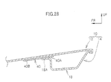
- a length L from the front end edge portions 30A of the open portions 30 to a front portion lower end 40A serving as a terminal end site of the front bumper 40 is a substantially constant L at a side cross-section at all positions in the vehicle width direction
- the length L from the front portion lower end 40A of the front bumper 40 to the front end edge portion 30A of the open portions 30 is a line length of an arcuately line along the outer contour of the vehicle body.
- the shape, when seen in plan view, of a front end edge portion 16H of the inner front 16 is an arcuate line shape where the vehicle width-direction center portion thereof is convex towards the vehicle body front.
- the front end edge portions 30A of the open portions 30 formed in the inner panel 14 are set on an arcuate line where the vehicle width-direction center portion thereof is concave towards the vehicle body front.
- the length L from the front end edge portions 30A of the open portions 30 to the front portion lower end 40A of the front bumper 40 are substantially constant at the side cross-section at all positions in the vehicle width direction.
- the length L + H reaching a road surface R from the front end edge portions 30A of the open portions 30 via the front bumper 40 are substantially constant at the side cross-section at all positions in the vehicle width direction.
- the length between the position on the hood at which an upper portion of the collision body hits and the front end edge portions 30A of the open portions 30 can be made substantially uniform, whereby the impact load on the upper portion of the collision body can be made uniform when the upper portion of the collision body collides with the front portion region of the hood 10.
- the shape, when seen in plan view, of the rear end edge portion 16G of the inner front 16 has an arcuate line shape where the vehicle width-direction center portion thereof is concave towards the vehicle body front
- the shape, when seen in plan view, of the front end edge portion 16H of the inner front 16 has an arcuate line shape where the vehicle width-direction center portion thereof is convex towards the vehicle body front.
- vehicle body front portion structure has been described in detail, but the invention is not limited to this embodiment. That other various embodiments within the scope of the invention are possible will be apparent to those skilled in the art.
- the number of the open portions is not limited to four and may be any number, such as one or more.
- the inner panel 14 of the hood 10 may have another divided structure.
- the inner panel 14 of the hood 10 may also have an integrated structure.
Landscapes
- Engineering & Computer Science (AREA)
- Chemical & Material Sciences (AREA)
- Combustion & Propulsion (AREA)
- Transportation (AREA)
- Mechanical Engineering (AREA)
- Superstructure Of Vehicle (AREA)
- Body Structure For Vehicles (AREA)
Applications Claiming Priority (4)
| Application Number | Priority Date | Filing Date | Title |
|---|---|---|---|
| JP2003189499A JP4300907B2 (ja) | 2003-07-01 | 2003-07-01 | 車両用フード構造 |
| JP2003191695A JP4300908B2 (ja) | 2003-07-04 | 2003-07-04 | 車両用フード構造 |
| JP2003193382A JP4259210B2 (ja) | 2003-07-08 | 2003-07-08 | 車体前部構造 |
| EP04015365A EP1493639B1 (de) | 2003-07-01 | 2004-06-30 | Fahrzeughaube und vorderer Karosserieaufbau |
Related Parent Applications (1)
| Application Number | Title | Priority Date | Filing Date |
|---|---|---|---|
| EP04015365A Division EP1493639B1 (de) | 2003-07-01 | 2004-06-30 | Fahrzeughaube und vorderer Karosserieaufbau |
Publications (3)
| Publication Number | Publication Date |
|---|---|
| EP1829770A2 true EP1829770A2 (de) | 2007-09-05 |
| EP1829770A3 EP1829770A3 (de) | 2007-10-10 |
| EP1829770B1 EP1829770B1 (de) | 2012-10-24 |
Family
ID=33437002
Family Applications (3)
| Application Number | Title | Priority Date | Filing Date |
|---|---|---|---|
| EP07110212A Expired - Fee Related EP1829756B1 (de) | 2003-07-01 | 2004-06-30 | Fahrzeughaube und vorderer Karosserieaufbau |
| EP04015365A Expired - Fee Related EP1493639B1 (de) | 2003-07-01 | 2004-06-30 | Fahrzeughaube und vorderer Karosserieaufbau |
| EP07110214A Expired - Fee Related EP1829770B1 (de) | 2003-07-01 | 2004-06-30 | Fahrzeughaubenstruktur und vorderer Karosserieaufbau |
Family Applications Before (2)
| Application Number | Title | Priority Date | Filing Date |
|---|---|---|---|
| EP07110212A Expired - Fee Related EP1829756B1 (de) | 2003-07-01 | 2004-06-30 | Fahrzeughaube und vorderer Karosserieaufbau |
| EP04015365A Expired - Fee Related EP1493639B1 (de) | 2003-07-01 | 2004-06-30 | Fahrzeughaube und vorderer Karosserieaufbau |
Country Status (3)
| Country | Link |
|---|---|
| US (1) | US7052079B2 (de) |
| EP (3) | EP1829756B1 (de) |
| DE (1) | DE602004030974D1 (de) |
Cited By (1)
| Publication number | Priority date | Publication date | Assignee | Title |
|---|---|---|---|---|
| DE102014003199A1 (de) * | 2014-03-04 | 2015-09-10 | GM Global Technology Operations LLC (n. d. Ges. d. Staates Delaware) | Fronthaube für ein Kraftfahrzeug |
Families Citing this family (21)
| Publication number | Priority date | Publication date | Assignee | Title |
|---|---|---|---|---|
| JP2005075176A (ja) * | 2003-09-01 | 2005-03-24 | Toyota Motor Corp | 車両用フード構造 |
| DE102004035430A1 (de) * | 2004-07-21 | 2006-03-16 | Adam Opel Ag | Haube für ein Kraftfahrzeug |
| WO2006025315A1 (ja) * | 2004-08-31 | 2006-03-09 | Toray Industries, Inc. | 自動車用ボンネット |
| FR2875777B1 (fr) * | 2004-09-24 | 2008-08-15 | Renault Sas | Capot de vehicule automobile pourvu d'une doublure renforcee |
| US8096611B2 (en) * | 2005-02-04 | 2012-01-17 | Toyota Jidosha Kabushiki Kaisha | Vehicle front-part structure |
| DE102006015403B4 (de) * | 2006-04-03 | 2019-07-11 | Audi Ag | Fronthaube für einen Personenkraftwagen |
| DE102006015402B4 (de) * | 2006-04-03 | 2009-11-26 | Audi Ag | Fronthaube für einen Personenkraftwagen |
| DE102006015409B4 (de) * | 2006-04-03 | 2014-12-18 | Audi Ag | Fronthaube für einen Personenkraftwagen |
| JP4062632B1 (ja) * | 2006-10-19 | 2008-03-19 | いすゞ自動車株式会社 | 車両前面構造 |
| US7469955B2 (en) * | 2007-05-29 | 2008-12-30 | Gm Global Technology Operations, Inc. | Rotatably-mountable bumper and method for cushioning contact between a vehicle hood and grill |
| FR2917700B1 (fr) * | 2007-06-19 | 2009-11-20 | Peugeot Citroen Automobiles Sa | Capot de vehicule a doublure garantissant un bon amortissement en cas de choc pieton |
| US7735908B2 (en) * | 2007-07-24 | 2010-06-15 | Gm Global Technology Operations, Inc. | Vehicle hood with sandwich inner structure |
| US7635157B2 (en) * | 2007-09-11 | 2009-12-22 | GM Global Technology Operation, INC | Vehicle hood assembly with rippled cushion support |
| US7690720B2 (en) * | 2008-01-31 | 2010-04-06 | Gm Global Technology Operations, Inc. | Energy absorbing vehicle hood assembly with asymmetric sandwich inner structure |
| JP4407755B2 (ja) * | 2008-02-04 | 2010-02-03 | トヨタ自動車株式会社 | 車両用フード構造 |
| DE102009023534B4 (de) * | 2009-05-30 | 2021-10-07 | Bayerische Motoren Werke Aktiengesellschaft | Karosserieteil mit einer Außenhaut und einer Unterstruktur |
| WO2012157100A1 (ja) * | 2011-05-18 | 2012-11-22 | トヨタ自動車株式会社 | 車両用フード構造 |
| DE102013014203A1 (de) | 2013-08-26 | 2015-02-26 | GM Global Technology Operations LLC (n. d. Ges. d. Staates Delaware) | Fronthaube für ein Kraftfahrzeug |
| DE102014002800A1 (de) * | 2014-02-26 | 2015-08-27 | GM Global Technology Operations LLC (n. d. Ges. d. Staates Delaware) | Fronthaube für ein Kraftfahrzeug |
| US9248866B2 (en) * | 2014-06-13 | 2016-02-02 | Toyota Motor Engineering & Manufacturing North America, Inc. | Hood assembly |
| US10800458B2 (en) * | 2019-02-14 | 2020-10-13 | Ford Global Technologies, Llc | Energy absorbing seal for a vehicle |
Citations (1)
| Publication number | Priority date | Publication date | Assignee | Title |
|---|---|---|---|---|
| JPH11321714A (ja) | 1998-05-13 | 1999-11-24 | Honda Motor Co Ltd | 自動車のボンネット |
Family Cites Families (19)
| Publication number | Priority date | Publication date | Assignee | Title |
|---|---|---|---|---|
| US5000997A (en) * | 1989-02-06 | 1991-03-19 | The Budd Company | Method for making a painted part and part made thereby |
| JPH081180Y2 (ja) * | 1989-07-26 | 1996-01-17 | マツダ株式会社 | 車両のボンネット構造 |
| JP3010862B2 (ja) * | 1991-12-03 | 2000-02-21 | トヨタ自動車株式会社 | エンジンフード構造 |
| JPH05278637A (ja) | 1992-04-03 | 1993-10-26 | Nissan Motor Co Ltd | 自動車用フード構造 |
| JPH0672355A (ja) | 1992-08-25 | 1994-03-15 | Showa Alum Corp | 自動車フード補強材 |
| US5273341A (en) * | 1992-11-23 | 1993-12-28 | Ford Motor Company | Hood sealing apparatus for a motor vehicle |
| JPH06312670A (ja) | 1993-04-28 | 1994-11-08 | Suzuki Motor Corp | 自動車のフロントフードストライカの取付構造 |
| CA2136134C (en) * | 1994-04-25 | 1999-07-27 | James E. Borchelt | Light weight steel auto body construction |
| JPH08318875A (ja) * | 1995-05-24 | 1996-12-03 | Honda Motor Co Ltd | エンジンフード |
| JP3531789B2 (ja) * | 1998-05-13 | 2004-05-31 | 本田技研工業株式会社 | 自動車のボンネット |
| FR2798356B1 (fr) * | 1999-09-09 | 2001-10-26 | Lorraine Laminage | Capot automobile renforce et leger |
| JP2001191962A (ja) | 2000-01-12 | 2001-07-17 | Toray Ind Inc | Frp補強自動車用水平パネル材 |
| JP4083368B2 (ja) | 2000-04-24 | 2008-04-30 | トヨタ自動車株式会社 | 車両のシール構造 |
| DE10038812A1 (de) | 2000-08-09 | 2002-02-21 | Volkswagen Ag | Frontklappe für ein Kraftfahrzeug |
| US7150496B2 (en) * | 2000-12-13 | 2006-12-19 | Kobe Steel, Ltd. | Panel structure for car body hood |
| GB0121523D0 (en) * | 2001-09-06 | 2001-10-24 | Itw Ltd | Hinge assembly |
| DE10159491B4 (de) * | 2001-12-04 | 2005-08-11 | Benteler Automobiltechnik Gmbh | Strukturbauteil für ein Kraftfahrzeug |
| JP4010223B2 (ja) * | 2002-10-18 | 2007-11-21 | トヨタ自動車株式会社 | 車両のフード構造 |
| JP4076487B2 (ja) * | 2003-09-25 | 2008-04-16 | トヨタ自動車株式会社 | 車両用フード構造 |
-
2004
- 2004-06-30 DE DE602004030974T patent/DE602004030974D1/de active Active
- 2004-06-30 EP EP07110212A patent/EP1829756B1/de not_active Expired - Fee Related
- 2004-06-30 US US10/879,743 patent/US7052079B2/en active Active
- 2004-06-30 EP EP04015365A patent/EP1493639B1/de not_active Expired - Fee Related
- 2004-06-30 EP EP07110214A patent/EP1829770B1/de not_active Expired - Fee Related
Patent Citations (1)
| Publication number | Priority date | Publication date | Assignee | Title |
|---|---|---|---|---|
| JPH11321714A (ja) | 1998-05-13 | 1999-11-24 | Honda Motor Co Ltd | 自動車のボンネット |
Cited By (1)
| Publication number | Priority date | Publication date | Assignee | Title |
|---|---|---|---|---|
| DE102014003199A1 (de) * | 2014-03-04 | 2015-09-10 | GM Global Technology Operations LLC (n. d. Ges. d. Staates Delaware) | Fronthaube für ein Kraftfahrzeug |
Also Published As
| Publication number | Publication date |
|---|---|
| EP1493639A2 (de) | 2005-01-05 |
| EP1829770B1 (de) | 2012-10-24 |
| EP1493639A3 (de) | 2005-11-16 |
| EP1829756A3 (de) | 2007-10-17 |
| EP1493639B1 (de) | 2011-01-12 |
| EP1829770A3 (de) | 2007-10-10 |
| DE602004030974D1 (de) | 2011-02-24 |
| EP1829756A2 (de) | 2007-09-05 |
| US7052079B2 (en) | 2006-05-30 |
| EP1829756B1 (de) | 2012-12-12 |
| US20050001453A1 (en) | 2005-01-06 |
Similar Documents
| Publication | Publication Date | Title |
|---|---|---|
| EP1493639B1 (de) | Fahrzeughaube und vorderer Karosserieaufbau | |
| EP2868553B1 (de) | Fahrzeugaufbaustruktur | |
| EP0421277B1 (de) | Vorderteilkonstruktion eines Kraftfahrzeuges | |
| US8960780B2 (en) | Vehicle side body structure | |
| CN102198843B (zh) | 车身侧部构造 | |
| KR101097018B1 (ko) | 측면 충돌 성능을 강화시킨 자동차용 도어 | |
| EP2557021B1 (de) | Struktur für eine verbindung am seitenabschnitt eines fahrzeugs | |
| JP3783546B2 (ja) | 車両のサイドシル構造 | |
| US7699385B2 (en) | Vehicle body structure | |
| US4469368A (en) | Passenger car body structure | |
| JP5482987B2 (ja) | 車両の前部車体構造 | |
| EP1389575B1 (de) | Vorderwagenaufbau eines Fahrzeuges | |
| JP3091702B2 (ja) | 支持構造付きの乗用車の前部構造 | |
| EP3527434B1 (de) | Stossdämpfungsstruktur für fahrzeuge | |
| CN113353019B (zh) | 车辆的前部车身结构 | |
| CN115352391A (zh) | 一种碰撞传感器的安装结构及车辆 | |
| JPH06171442A (ja) | バンパーの取付構造 | |
| JP2008068760A (ja) | 車体前部構造 | |
| JP2003063454A (ja) | 自動車の車体前部構造 | |
| CN115140192B (zh) | 车辆 | |
| CN114056436B (zh) | 车辆的前部车身结构 | |
| JP4300908B2 (ja) | 車両用フード構造 | |
| US11420685B2 (en) | Vehicle body | |
| CN220114694U (zh) | 侧围加强板及包括该侧围加强板的侧围总成、车辆 | |
| EP2428432B1 (de) | Vorderseitenchassis einer Fahrzeugkarosserie |
Legal Events
| Date | Code | Title | Description |
|---|---|---|---|
| PUAI | Public reference made under article 153(3) epc to a published international application that has entered the european phase |
Free format text: ORIGINAL CODE: 0009012 |
|
| 17P | Request for examination filed |
Effective date: 20070613 |
|
| AC | Divisional application: reference to earlier application |
Ref document number: 1493639 Country of ref document: EP Kind code of ref document: P |
|
| AK | Designated contracting states |
Kind code of ref document: A2 Designated state(s): DE FR GB |
|
| PUAL | Search report despatched |
Free format text: ORIGINAL CODE: 0009013 |
|
| AK | Designated contracting states |
Kind code of ref document: A3 Designated state(s): DE FR GB |
|
| AKX | Designation fees paid |
Designated state(s): DE FR GB |
|
| GRAP | Despatch of communication of intention to grant a patent |
Free format text: ORIGINAL CODE: EPIDOSNIGR1 |
|
| GRAS | Grant fee paid |
Free format text: ORIGINAL CODE: EPIDOSNIGR3 |
|
| GRAA | (expected) grant |
Free format text: ORIGINAL CODE: 0009210 |
|
| RIN1 | Information on inventor provided before grant (corrected) |
Inventor name: ENDO, YOSHIHIDE Inventor name: MIZUKAMI, KOUICHI Inventor name: MIYADERA, KAZUHIKO |
|
| AC | Divisional application: reference to earlier application |
Ref document number: 1493639 Country of ref document: EP Kind code of ref document: P |
|
| AK | Designated contracting states |
Kind code of ref document: B1 Designated state(s): DE FR GB |
|
| REG | Reference to a national code |
Ref country code: GB Ref legal event code: FG4D |
|
| REG | Reference to a national code |
Ref country code: DE Ref legal event code: R096 Ref document number: 602004039826 Country of ref document: DE Effective date: 20121220 |
|
| RAP2 | Party data changed (patent owner data changed or rights of a patent transferred) |
Owner name: TOYOTA JIDOSHA KABUSHIKI KAISHA |
|
| PLBE | No opposition filed within time limit |
Free format text: ORIGINAL CODE: 0009261 |
|
| STAA | Information on the status of an ep patent application or granted ep patent |
Free format text: STATUS: NO OPPOSITION FILED WITHIN TIME LIMIT |
|
| 26N | No opposition filed |
Effective date: 20130725 |
|
| REG | Reference to a national code |
Ref country code: DE Ref legal event code: R097 Ref document number: 602004039826 Country of ref document: DE Effective date: 20130725 |
|
| REG | Reference to a national code |
Ref country code: DE Ref legal event code: R084 Ref document number: 602004039826 Country of ref document: DE |
|
| REG | Reference to a national code |
Ref country code: GB Ref legal event code: 746 Effective date: 20150330 |
|
| REG | Reference to a national code |
Ref country code: DE Ref legal event code: R084 Ref document number: 602004039826 Country of ref document: DE Effective date: 20150326 |
|
| REG | Reference to a national code |
Ref country code: FR Ref legal event code: PLFP Year of fee payment: 13 |
|
| REG | Reference to a national code |
Ref country code: FR Ref legal event code: PLFP Year of fee payment: 14 |
|
| REG | Reference to a national code |
Ref country code: FR Ref legal event code: PLFP Year of fee payment: 15 |
|
| PGFP | Annual fee paid to national office [announced via postgrant information from national office to epo] |
Ref country code: DE Payment date: 20190618 Year of fee payment: 16 |
|
| PGFP | Annual fee paid to national office [announced via postgrant information from national office to epo] |
Ref country code: FR Payment date: 20190510 Year of fee payment: 16 |
|
| PGFP | Annual fee paid to national office [announced via postgrant information from national office to epo] |
Ref country code: GB Payment date: 20190626 Year of fee payment: 16 |
|
| REG | Reference to a national code |
Ref country code: DE Ref legal event code: R119 Ref document number: 602004039826 Country of ref document: DE |
|
| GBPC | Gb: european patent ceased through non-payment of renewal fee |
Effective date: 20200630 |
|
| PG25 | Lapsed in a contracting state [announced via postgrant information from national office to epo] |
Ref country code: GB Free format text: LAPSE BECAUSE OF NON-PAYMENT OF DUE FEES Effective date: 20200630 Ref country code: FR Free format text: LAPSE BECAUSE OF NON-PAYMENT OF DUE FEES Effective date: 20200630 |
|
| PG25 | Lapsed in a contracting state [announced via postgrant information from national office to epo] |
Ref country code: DE Free format text: LAPSE BECAUSE OF NON-PAYMENT OF DUE FEES Effective date: 20210101 |