EP1827272B1 - Intramedullärer Marknagel - Google Patents
Intramedullärer Marknagel Download PDFInfo
- Publication number
- EP1827272B1 EP1827272B1 EP05848257A EP05848257A EP1827272B1 EP 1827272 B1 EP1827272 B1 EP 1827272B1 EP 05848257 A EP05848257 A EP 05848257A EP 05848257 A EP05848257 A EP 05848257A EP 1827272 B1 EP1827272 B1 EP 1827272B1
- Authority
- EP
- European Patent Office
- Prior art keywords
- intramedullary nail
- nail
- band
- core
- intramedullary
- Prior art date
- Legal status (The legal status is an assumption and is not a legal conclusion. Google has not performed a legal analysis and makes no representation as to the accuracy of the status listed.)
- Expired - Lifetime
Links
Images

Classifications
-
- A—HUMAN NECESSITIES
- A61—MEDICAL OR VETERINARY SCIENCE; HYGIENE
- A61B—DIAGNOSIS; SURGERY; IDENTIFICATION
- A61B17/00—Surgical instruments, devices or methods
- A61B17/56—Surgical instruments or methods for treatment of bones or joints; Devices specially adapted therefor
- A61B17/58—Surgical instruments or methods for treatment of bones or joints; Devices specially adapted therefor for osteosynthesis, e.g. bone plates, screws or setting implements
- A61B17/68—Internal fixation devices, including fasteners and spinal fixators, even if a part thereof projects from the skin
- A61B17/72—Intramedullary devices, e.g. pins or nails
- A61B17/7208—Flexible pins, e.g. ENDER pins
-
- A—HUMAN NECESSITIES
- A61—MEDICAL OR VETERINARY SCIENCE; HYGIENE
- A61B—DIAGNOSIS; SURGERY; IDENTIFICATION
- A61B17/00—Surgical instruments, devices or methods
- A61B17/56—Surgical instruments or methods for treatment of bones or joints; Devices specially adapted therefor
- A61B17/58—Surgical instruments or methods for treatment of bones or joints; Devices specially adapted therefor for osteosynthesis, e.g. bone plates, screws or setting implements
- A61B17/68—Internal fixation devices, including fasteners and spinal fixators, even if a part thereof projects from the skin
- A61B17/72—Intramedullary devices, e.g. pins or nails
- A61B17/7283—Intramedullary devices, e.g. pins or nails with special cross-section of the nail
Definitions
- the invention relates to an intramedullary nail according to the preamble of the main claim, the document WO 97/49348 A is derived.
- Another device for stabilizing long bone fractures and joints is known DE 38 35 682 A1 comprising, as stabilizing elements, single or multi-threaded helical springs wound in part around a core in the form of an elastically deformable wire or a bundle of elastically deformable wires.
- a helical spring can be designed at the ends with a device for fixing to the bone.
- a disadvantage of this known device is the indeterminacy of the position of the coil springs and the impossibility of rotation prevention as well as a fixation of individual fragments in the region of a fracture, since the spring properties of the coil springs can not hinder there.
- a nail system for intramedullary osteosynthesis in shaft fractures of all kinds is known DE 197 31 298 A1 comprising a tubular outer body with apertures from which hooks extend outwardly, which can be pivoted by operating an inner body to the outside, whereby the hooks should be able to create on the inner wall of a long bone.
- This nail system is extremely complex and has many components, but can in principle produce only point contacts with the inner surface of a long bone and this only in a narrow and identical length over the peripheral area.
- Simpler intramedullary nails for locking nailing are known, but their installation during an intervention can only be controlled by means of intraoperative X-ray imaging, which is extremely stressful not only for a patient, but especially for the OR staff because of the duration.
- transverse screws in the bone, including, in particular in long thigh bone, but also in the humerus and lower leg complex targeting devices required are to be able to pinpoint such transverse screws with minimal injury to the skin through them.
- These surgical wounds which are also to be introduced into a limb, must be laboriously treated after an operation but also after an operative removal of the transverse screws, which entails additional burdens for a patient.
- the object of the invention is to provide an intramedullary nail that is simple in design, very practical, easy, fast, safe and can be used with only minor use of intraoperative X-ray imaging, without requiring intervention in intact areas of a limb.
- the intramedullary nail which is particularly suitable for the closed reduction of a fracture of a long bone by insertion into a hole in the medullary cavity, is characterized in that it has a nail core, at the front region of which the beginning of an outer band is fixed around the nail core is wound and the end of which is fixed lubverriegelbar in the rear around the nail core, which widens in a rotation opposite to its winding the radial contour of the intramedullary nail.
- the band consists of resilient material, such as surgical steel, titanium or body-friendly plastic
- the desired properties of the intramedullary nail in terms of the required contact force as well as the nature and the course of the deformation advantageously initially from the front of the intramedullary nail optimally define the medullary waistline until the end of a medullary canal widens again.
- several inner or outer bands may be the same or, above all, wound in opposite directions and one or more around the nail core, wherein in a single-layer version of the inner bands they are wound directly around the core and at a single-layered embodiment of the outer bands are wound around the inner bands around.
- the radial outer surfaces of the inner band and the inner radial surfaces of the outer band are designed to be rough as a mutual functional surfaces, so that the common contact surfaces of the bands stabilizing points of an inserted into a through hole of a bone and strained intramedullary nail in the form of a force and generate frictional connection. As a result, the stability of the intramedullary nail is further increased.
- the bands are biased in the uninstalled state and locked around the nail core in the region of its rear ends against each other or against the nail core via a tensioning and locking mechanism, so that they turn up automatically after unlocking against the direction of rotation of the winding and so that the outer diameter of the intramedullary nail either uniformly or in an advantageous manner so expand that the outer band applies to the inner contours of the medullary canal of a long bone.
- a tensioning and locking mechanism so that they turn up automatically after unlocking against the direction of rotation of the winding and so that the outer diameter of the intramedullary nail either uniformly or in an advantageous manner so expand that the outer band applies to the inner contours of the medullary canal of a long bone.
- Such a function can be produced, for example, in that the inner and / or the outer band have different widths or thicknesses in different regions of the nail core or else the elasticity of the inner band and / or the outer band is differentially elastic in different ranges of the nail core is.
- Such an advantageous construction makes it possible furthermore and also in non-prestressed bands, that the outer band when turning against the direction of rotation initially applies in the region of the head piece of the intramedullary nail to the inner contour of a bone and only on further turning up first in the middle region of the medullary waist of Long bone and then applied in the end of the intramedullary nail to the re-expanding area of the medullary cavity.
- the intramedullary nail is equipped at its rear end with a clamping and locking mechanism having at least one inner sleeve and an outer sleeve, the mutual latches or locking surfaces such as have self-locking tapered seats, wherein the inner band is fixed to the rotatable around the nail core inner sleeve and the outer band on the rotatable about the nail core outer sleeve.
- the intramedullary nail has at its rear area contact surfaces for the arrangement of an adapter as a further mechanical device for stabilizing bone fractures, as is known for a fracture of a femoral neck bone of a femur.
- a thread is advantageously provided on which the inner sleeve of the clamping and locking mechanism is screwed, so as to ensure that in a mutual locking of the inner sleeve and the outer sleeve a defined position of the clamping and locking mechanism is present to the nail core ,
- the nail core is hollow and pass through a sleeve and / or a shaft, so that the beginning of an inner and / or outer band can be set at the front of the head piece of the intramedullary nail, the rear End of the intramedullary nail this can be unwound and clamped from behind against its direction of rotation via a suitably trained clamping and locking mechanism against its direction of rotation.
- An inventive development of the intramedullary nail has about two outer bands of which one of the front portion of the intramedullary nail and one of the rear portion of the intramedullary nail can be rotated, so that an optimal adaptation of the band to the medullary canal of both sides trumpetingly widening medullary canal and thus a optimal lateral cortical support is possible.
- the intramedullary nail can be formed straight or curved as needed or be plastically bendable according to the required spatial form.
- the nail core of an intramedullary nail can advantageously be designed in several parts, so that these parts can rotate against each other. This greatly enhances the possibilities for constructive design.
- two bands wound against each other are connected to each other at their front ends or a band from the outset in one piece and wound from its front end in opposite directions around the nail core, so that the nail core can be formed shortened and extends only to a partial area in the direction of the front end of the intramedullary nail.
- the nail core is reduced even to the tensioning and locking mechanism, which quasi in the installed state, a stable rigid mesh grid remains as an intramedullary nail, resulting in an enormous material and weight savings, as well as a very cost-effective variant.
- the ends of the bands 3 and 4 are arranged on an outer bushing 8 and an inner bushing 9 of the tensioning and locking mechanism 7 and there, for example, also welded by means of a laser.
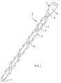
- the oppositely wound bands 3 and 4 overlap at contact surfaces 6, wherein the mutually facing surfaces of the bands 3 and 4 are formed so that there is a non-positive and frictional fixation, which stabilizes the entire intramedullary nail 1.
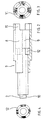
- the outer sleeve 8 and the inner sleeve 9 have mutual detents and are set by a thread 10 on the end of the nail core 2 and in the inner sleeve 9 on this rotatable.
- a significantly higher number of turns of the inner band 3 as well as the outer band 4 so that there is a considerable higher number of common contact surfaces 6 between the bands 3 and 4, and thus an extremely enlarged Stiffness of the intramedullary nail 1 and an associated optimized fixation of a fracture is present.
- FIGS. 2 to 4 also show only basic functional examples of the clamping and locking mechanism 7 and its key teeth 11 for attaching a mounting aid, not shown, and a section through a réelleverrastung 12 of the inner sleeve 9 and outer sleeve. 8
- Fig. 5 Also shown only as an example embodiment also has a significantly higher number of turns in a practical embodiment and here only a single formed by the head piece 5 tip from oppositely wound band whose inner windings form the inner band 3 and the outer windings the outer band 4.
- the subject nail core 2 is here completely reduced to the tensioning and closing mechanism 7 or is replaced by a free air space. Also, this version allows an outward force-free clamping of the intramedullary nail, as with all other versions mentioned above, without mechanical restoring forces would have to be absorbed by a bone or introduced into this.
Landscapes
- Health & Medical Sciences (AREA)
- Orthopedic Medicine & Surgery (AREA)
- Surgery (AREA)
- Life Sciences & Earth Sciences (AREA)
- Heart & Thoracic Surgery (AREA)
- Animal Behavior & Ethology (AREA)
- Engineering & Computer Science (AREA)
- Biomedical Technology (AREA)
- Neurology (AREA)
- Medical Informatics (AREA)
- Molecular Biology (AREA)
- Nuclear Medicine, Radiotherapy & Molecular Imaging (AREA)
- General Health & Medical Sciences (AREA)
- Public Health (AREA)
- Veterinary Medicine (AREA)
- Surgical Instruments (AREA)
- Prostheses (AREA)
- Transplanting Machines (AREA)
Description
- Die Erfindung betrifft einen Marknagel gemäß dem Oberbegriff des Hauptanspruchs, der vom Dokument
WO 97/49348 A - Es ist eine weitere Vorrichtung zur Stabilisierung von Röhrenknochenbrüchen sowie von Gelenken bekannt
DE 38 35 682 A1 , die als Stabilisierungselemente ein- oder mehrgängig ineinander gewickelte Schraubenfedern aufweist, die zum Teil um eine Seele in Form eines elastisch verformbaren Drahtes oder eines Bündels von elastisch verformbaren Drähten herumgewickelt sind. Eine solche Schraubenfeder kann an den Enden mit einer Einrichtung zum Festlegen am Knochen ausgeführt sein. - Nachteilig an dieser bekannten Vorrichtung ist die Unbestimmtheit der Lage der Schraubenfedern sowie die Unmöglichkeit einer Rotationsverhinderung wie auch einer Fixierung einzelner Bruchstücke im Bereich einer Fraktur, da sich die Federeigenschaften der Schraubenfedern dort nicht behindern lassen.
- Weiterhin ist ein Nagelsystem für die intramedulläre Osteosynthese bei Schaftfrakturen aller Art bekannt,
DE 197 31 298 A1 , welches einen rohrförmigen Außenkörper mit Durchbrüchen aufweist, aus denen sich Haken nach außen erstrecken, die durch Betätigung eines Innenkörpers nach außen geschwenkt werden können, wodurch sich die Haken an der Innenwand eines Röhrenknochens anlegen können sollen. - Dieses Nagelsystem ist extrem aufwändig und weist sehr viele Bauteile auf, kann aber prinzipbedingt nur Punktkontakte mit der Innenfläche eines Röhrenknochens erzeugen und diese auch nur in einem engen und über die Länge identischen Umfangsbereich.
- Einfachere Marknägel zur Verriegelungsnagelung sind bekannt, deren Einbau während eines Eingriffs jedoch nur mittels intraoperativer Röntgendarstellung kontrolliert werden kann, was aufgrund der Dauer nicht nur für einen Patienten, sondern insbesondere für das OP-Personal äußerst belastend ist.
- Des Weiteren müssen solche einfachen Marknägel mittels Querschrauben im Knochen gesichert werden, wozu insbesondere bei langen Oberschenkelknochen, aber auch bei Oberarm- und Unterschenkelknochen aufwändige Zielgeräte erforderlich sind, um solche Querschrauben unter möglichst geringer Verletzung der Haut durch diese hindurch punktgenau setzen zu können. Diese zusätzlich in eine Extremität einzubringenden Operationswunden müssen nach einer Operation aber auch nach einer operativen Entfernung der Querschrauben aufwändig versorgt werden, was zusätzliche Belastungen für einen Patienten mit sich bringt.
- Aufgabe der Erfindung ist es, einen Marknagel zur Verfügung zu stellen, der einfach aufgebaut ist, sehr praxisorientiert, leicht, schnell, sicher und bei nur geringem Einsatz von intraoperativer Röntgendarstellung eingesetzt werden kann, ohne dabei Eingriffe in unversehrte Bereiche einer Extremität zu erfordern.
- Die Lösung dieser Aufgabe ergibt sich in Verbindung mit den Oberbegriffsmerkmalen in erfindungsgemäßer Art und Weise aus den Merkmalen des kennzeichnenden Teils des Hauptanspruchs.
- Der Marknagel, der sich insbesondere zur geschlossenen Reposition einer Fraktur eines Röhrenknochens durch Einsetzen in eine Bohrung in dessen Markhöhle eignet, ist dadurch gekennzeichnet, dass er einen Nagelkern aufweist, an dessen vorderem Bereich der Anfang eines äußeren Bandes festgelegt ist, welches um den Nagelkern herum aufgewickelt ist und dessen Ende im hinteren Bereich um den Nagelkern drehverriegelbar festgelegt ist, wobei sich bei einer Drehung entgegen seiner Aufwickelrichtung die radiale Kontur des Marknagels erweitert. Hierdurch wird vorteilhaft erreicht, dass sich die Außenseite des Bandes an der Innenseite einer Durchgangsbohrung bzw. unmittelbar an die Innenseite des Markraumes eines Röhrenknochens anlegen kann bzw. durch ein weiteres Drehen entgegen der Aufwickelrichtung eine radial wirkende Kraft erzeugt werden kann, mit der die Einzelteile eines Knochens optimal ausgerichtet und repositioniert geklemmt werden können, wodurch ein optimales Heilungsergebnis erzielt werden kann.
- Der technische Aufbau eines solchen Marknagels ist extrem einfach, leicht von jedem Notfallarzt zu verstehen und dadurch auch sehr sicher in der korrekten Anwendung. Auf den Einsatz von distalen Fixierschrauben des Nagels kann hier vollständig verzichtet werden, so dass eine postoperative Schnittwundenversorgung in diesem Bereich nicht mehr erforderlich wird.
- Durch die Klemmkraft des Bandes wird eine starke seitliche kortikale Abstützung und damit eine optimale Frakturstabilisierung erreicht, was des Weiteren zu einem schnelleren Ablauf der Frakturheilung führt. Frakturheilungsstörungen in Folge mangelhafter Frakturfixation können bei der Verwendung des erfinderischen Marknagels vollständig ausgeschlossen werden. Längsgespaltene Knochenbrüche oder solche, die sehr nahe an einem Gelenk vorliegen, können mit dem erfindungsgemäßen Marknagel jedoch nicht behandelt werden. Zur Entfernung des Marknagels werden die Bänder wieder stärker um den Nagelkern herum aufgewickelt, wodurch sich der Außendurchmesser des Marknagels wieder verringert, sodass er problemlos aus der Bohrung oder der Markhöhle herausgezogen werden kann.
- Weitere vorteilhafte Ausführungsformen der Erfindung ergeben sich mit und in Kombination aus den nachfolgenden Unteransprüchen.
- Als besonders vorteilhaft ist eine Ausführung hervorzuheben, bei der im vorderen Bereich des Marknagels der Anfang eines weiteren inneren Bandes festgelegt ist, welches unter dem äußeren Band um den Nagelkern herum aufgewickelt ist und dessen Ende ebenfalls im hinteren Bereich des Marknagels drehverriegelbar um den Nagelkern festgelegt ist. Ein solches inneres Band vergrößert bei einer Drehung entgegen seiner Aufwicklungsrichtung ebenfalls den Außendurchmesser des Marknagels bzw. legt sich mit seiner Außenseite an der Innenseite des äußeren Bandes an und stabilisiert so das Band und damit den gesamten Marknagel. Diese Konstruktion ermöglicht die Verwirklichung einer hohen Steifigkeit, die etwa der eines dünnen Rohres entsprechen kann.
- Dadurch, dass das Band aus federelastischem Material besteht, etwa aus chirugischem Stahl, Titan oder körperfreundlichem Kunststoff, lassen sich die gewünschten Eigenschaften des Marknagels hinsichtlich der erforderlichen Kontaktkraft wie auch die Art und der Ablauf der Verformung, vorteilhafterweise zunächst von dem vorderen Bereich des Marknagels über die Markraumtaille bis zum sich wieder erweiternden Ende eines Markraumes optimal festlegen.
- Gemäß weiterer vorteilhaften Ausführungsformen der Erfindung können auch mehrere innere oder äußere Bänder gleich- oder vor allen Dingen gegensinnig sowie ein- oder mehrgängig um den Nagelkern herum aufgewickelt sein, wobei bei einer einlagigen Version der inneren Bänder diese unmittelbar um den Kern herum aufgewickelt sind und bei einer einlagigen Ausführungsform der äußeren Bänder diese um die inneren Bänder herum aufgewickelt sind.
Dieser Variationsreichtum erlaubt es, für die häufigsten Arten von Frakturen von Knochen beliebiger Größe jeweils einen optimal angepassten Marknagel zur Verfügung stellen zu können, da die geforderte Festigkeit quasi beliebig hoch eingestellt werden kann. - Besonders vorteilhaft ist es, dass die radialen Außenflächen des inneren Bandes und die radialen Innenflächen des äußeren Bandes als gegenseitige Funktionsflächen rau ausgebildet sind, so dass die gemeinsamen Kontaktflächen der Bänder Stabilisierungspunkte eines in eine Durchgangsbohrung eines Knochens eingesetzten und verspannten Marknagels in Form einer kraft- und reibschlüssigen Verbindung erzeugen. Hierdurch wird die Stabilität des Marknagels weiter vergrößert.
- Bei einer bevorzugten Ausführungsform der Erfindung sind die Bänder im unverbauten Zustand vorgespannt und um den Nagelkern im Bereich ihrer hinteren Enden gegeneinander oder gegen den Nagelkern über einen Spann- und Verschlussmechanismus verriegelt, so dass sie sich nach einer Entriegelung selbständig entgegen dem Drehsinn der Wickelung aufdrehen und so den Außendurchmesser des Marknagels entweder gleichmäßig oder aber in vorteilhafter Art und Weise so aufweiten, dass sich das äußere Band an die Innenkonturen des Markraumes eines Röhrenknochens anlegt. Eine solche Funktion kann beispielsweise dadurch erzeugt werden, dass das innere und/ oder das äußere Band in unterschiedlichen Bereichen des Nagelkerns unterschiedlich breit oder dick ausgebildet sind oder aber das das innere Band und/ oder das äußere Band in unterschiedlichen Breichen des Nagelkerns unterschiedlich stark elastisch vorgespannt ist. Denkbar ist es auch, dass beispielsweise das äußere Band über seine gesamten Länge oder zumindest teilweise, von der Nagelspitze ausgesehen etwa über die ersten 2/3 seiner Länge einen sich kontinuierlich verändernden Querschnitt, insbesondere eine zunehmende Breite aufweist, um die geforderte Funktion zu erfüllen.
- Eine solche vorteilhafte Konstruktion ermöglicht es des Weiteren und auch bei nicht vorgespannten Bändern, dass das äußere Band beim Aufdrehen gegen den Drehsinn sich zunächst im Bereich des Kopfstückes des Marknagels an die Innenkontur eines Knochens anlegt und erst beim weiteren Aufdrehen zunächst im mittleren Bereich der Markraumtaille eines Röhrenknochens und anschließend im Endbereich des Marknagels an den sich wieder erweiternden Bereich des Markraumes anlegt.
- Zur Sicherstellung der Funktion ist der Marknagel an seinem hinteren Ende mit einem Spann- und Verschlussmechanismus ausgestattet, der zumindest eine Innenbuchse und eine Außenbuchse aufweist, die gegenseitige Rasten oder Rastflächen wie etwa selbsthemmende Kegelsitze besitzen, wobei das innere Band an der um den Nagelkern drehbaren Innenbuchse und das äußere Band an der ebenfalls um den Nagelkern drehbaren Außenbuchse festgelegt ist.
- Zum Einsetzen des Marknagels ist dieser mit einer davon lösbaren Montagehilfe ausgestattet, die Betätigungsvorrichtungen für den Spann- und Verschlussmechanismus aufweisen.
- Vorteilhafterweise besitzt der Marknagel an seinem hinteren Bereich Kontaktflächen zur Anordnung eines Adapters als weitere mechanische Vorrichtung zur Stabilisierung von Knochenbrüchen, wie sie etwa für eine Fraktur eines Schenkelhalsknochens eines Oberschenkelknochens bekannt ist.
- Auf dem Ende des Nagelkerns ist vorteilhafterweise ein Gewinde vorgesehen, auf dem die Innenbuchse des Spann- und Verschlussmechanismus aufgeschraubt ist, so dass gewährleistet ist, dass bei einem gegenseitigen Verrasten der Innenbuchse und der Außenbuchse eine definierte Position des Spann- und Verschlussmechanismus zum Nagelkern vorhanden ist.
- Bei einer weiteren vorteilhaften Ausgestaltung des Gegenstandes der Erfindung ist der Nagelkern hohl ausgebildet und von einer Hülse und/ oder einer Welle durchtreten, so dass am vorderen Bereich des Kopfstückes des Marknagels der Anfang eines inneren und/ oder äußeren Bandes festgelegt werden kann, wobei vom hinteren Ende des Marknagels dieses über einen entsprechend ausgebildeten Spann- und Verschlussmechanismus von hinten gegen seine Drehrichtung abge-wickelt und aufgespannt werden kann.
- Eine erfinderische Weiterbildung des Marknagels besitzt etwa zwei äußere Bänder von denen eines vom vorderen Bereich des Marknagels aus und eines vom hinteren Bereich des Marknagels aus aufdrehbar ist, so dass eine optimale Anpassung des Bandes an den sich von einer Markraumtaillie beidseitig trompetenhaft erweiternden Markraum und damit eine optimale seitliche kortikale Abstützung möglich wird.
- Der Marknagel kann je nach Bedarf gerade oder gebogen ausgebildet oder auch entsprechend der geforderten Raumform plastisch verbiegbar sein.
- Weiterhin kann der Nagelkern eines Marknagels in vorteilhafter Weise mehrteilig ausgebildet sein, sodass sich diese Teile gegeneinander verdrehen lassen. Dies erweitert die Möglichkeiten zur konstruktiven Gestaltung sehr wesentlich.
- Bei einer weiteren sehr vorteilhaften Ausführungsform der Erfindung sind zwei gegeneinander aufgewickelte Bänder an Ihren vorderen Enden miteinander verbunden oder aber ein Band von vorne herein einteilig ausgebildet und von seinem vorderen Ende aus gegensinnig um den Nagelkern aufgewickelt ist, sodass der Nagelkern verkürzt ausgebildet sein kann und sich nur bis zu einem Teilbereich in Richtung des vorderen Endes des Marknagels erstreckt. Bei einer extremen Ausführungsform dieser Ausgestaltung ist der Nagelkern sogar bis auf den Spann- und Verschlussmechanismus reduziert, wodurch quasi im Einbauzustand ein stabiles starres Netzgitter als Marknagel übrig bleibt, was zu einer enormen Material- und Gewichtseinsparung führt, wie auch zu einer sehr kostengünstigen Variante.
- Nachfolgend ist ein Ausführungsbeispiel der Erfindung anhand der Zeichnungen näher beschrieben. Es zeigen:
- Fig. 1
- eine grobe Skizze eines Marknagels,
- Fig. 2
- eine geschnittene Teilansicht eines Spann- und Verschlussmechanismus,
- Fig. 3
- einen Schnitt durch eine Schlüsselverzahnung eines Spann- und Verschlussmechanismus,
- Fig. 4
- einen Schnitt durch eine Innenverrastung von Innen- und Außenbuchse und
- Fig. 5
- eine grobe Skizze eines Marknagels mit stark reduziertem Nagelkern.
- Im hinteren Bereich des Marknagels 1 sind die Enden der Bänder 3 und 4 an einer Außenbuchse 8 bzw. einer Innenbuchse 9 des Spann- und Verschlussmechanismus 7 angeordnet und dort beispielsweise ebenfalls mittels eines Laser verschweißt. Die gegensinnig aufgewickelten Bänder 3 und 4 überdecken sich an Kontaktflächen 6, wobei die zueinander gerichteten Oberflächen der Bänder 3 und 4 so ausgebildet sind, dass dort eine kraft- und reibschlüssige Fixierung erfolgt, die den gesamten Marknagel 1 stabilisiert.
- Die Außenbuchse 8 und die Innenbuchse 9 weisen gegenseitige Rastungen auf und sind über ein Gewinde 10 auf dem Ende des Nagelkerns 2 und in der Innenbuchse 9 auf dieser verdrehbar festgelegt.
- Die in
Fig. 1 nur beispielhaft dargestellte Ausführungsform weist in einer praxisorientierten Ausführungsform eine deutlich höhere Anzahl von Windungen des inneren Bandes 3 wie auch des äußeren Bandes 4 auf, so dass sich eine erhebliche höhere Anzahl an gemeinsamen Kontaktflächen 6 zwischen den Bändern 3 und 4 ergibt und damit eine extrem vergrößerte Steifigkeit des Marknagels 1 und eine damit verbundene optimierte Fixierung einer Fraktur vorhanden ist. - Die
Figuren 2 bis 4 zeigen ebenfalls nur prinzipielle Funktionsbeispiele des Spann- und Verschlussmechanismus 7 bzw. dessen Schlüsselverzahnung 11 zum Ansetzen einer nicht dargestellten Montagehilfe und einen Schnitt durch eine Innenverrastung 12 von Innenbuchse 9 und Außenbuchse 8. - Die in
Fig. 5 ebenfalls nur beispielhaft dargestellte Ausführungsform besitzt in einer praxisorientierten Ausführungsform ebenfalls eine deutlich höhere Anzahl von Windungen und hier nur ein einzelnes, von der als Kopfstück 5 ausgebildeten Spitze aus gegensinnig aufgewickeltes Band, dessen innere Wicklungen das inner Band 3 bilden und die äußeren Wicklungen das äußere Band 4. Der gegenständliche Nagelkern 2 ist hier bis auf der Spann- und Verschlussmechanismus 7 vollständig reduziert bzw. wird durch eine freien Luftraum ersetzt. Auch diese Version ermöglicht ein nach außen kräftefreies Verspannen des Marknagels, wie bei allen anderen vorgenannten Versionen auch, ohne dass mechanische Rückstellkräfte von einem Knochen aufgenommen oder in diesen eingeleitet werden müssten.
Claims (19)
- Marknagel, insbesondere zur geschlossenen Reposition einer Fraktur eines Röhrenknochens durch Einsetzen in eine Bohrung in dessen Markhöhle, wobei der Marknagel (1) einen Nagelkern (2) aufweist, und ein Band (4), welches um den Nagelkern (2) herum aufgewickelt ist, dadurch gekennzeichnet, dass an vorderem Bereich des Marknagels (1) ein Kopfstück (5) vorgesehen ist, an dem der Anfang des Bandes (4) festgelegt ist, und das Band (4) an dessen Ende im hinteren Bereich um den Nagelkern (2) drehverriegelbar festgelegt ist und welches bei einer Drehung entgegen seiner Aufwickelrichtung die radiale Kontur des Marknagels (1) erweitert.
- Marknagel nach Anspruch 1, dadurch gekennzeichnet, dass im vorderen Bereich des Nagelkerns (2) der Anfang eines weiteren inneren Bandes (3) festgelegt ist, welches unter dem Band (4) um den Nagelkern (2) herum aufgewickelt und dessen Ende im hinteren Bereich um den Nagelkern (2) drehverriegelbar festgelegt ist und welches sich bei einer Drehung entgegen dem Wickelsinn im Bereich von gemeinsamen Kontaktflächen (6) mit dem äußeren Band (4) an dieses anlegt und den Marknagel (1) stabilisiert.
- Marknagel nach Anspruch 2, dadurch gekennzeichnet, dass die Bänder (3; 4) gleich- oder gegensinnig um den Nagelkern (2) herum aufgewickelt sind.
- Marknagel nach Anspruch 2 oder 3, dadurch gekennzeichnet, dass zwei oder mehr Bänder (3; 4) im gleichen Wickelsinn mehrgängig um den Nagelkern (2) herum aufgewickelt sind.
- Marknagel nach einem der Ansprüche 2 bis 4, dadurch gekennzeichnet, dass das innere Band (3) entlang seiner radialen Außenflächen und das äußere Band (4) entlang seiner radialen Innenflächen als gegenseitige Funktionsflächen ausgebildet sind, die als gemeinsame Kontaktflächen (6) Stabilisierungspunkte des in eine Durchgangsbohrung eines Knochens eingesetzten und verspannten Marknagels (1) in Form einer kraft- und reibschlüssigen Verbindung bilden.
- Marknagel nach einem der Ansprüche 2 bis 5, dadurch gekennzeichnet, dass das äußere Band (4) und/ oder das innere Band (3) im unverbauten Zustand vorgespannt am Nagelkern (2) festgelegt sind/ ist oder dass deren hinteren Enden und das Ende des jeweils anderen Bandes (3; 4) gegeneinander verriegelt sind.
- Marknagel nach einem der Ansprüche 2 bis 6, dadurch gekennzeichnet, dass das gegen den Wickelsinn abgewickeltes äußere Band (4) so ausgebildet ist, dass es sich an die Innenkonturen des Markraumes eines Röhrenknochens anlegt.
- Marknagel nach einem der Ansprüche 2 bis 7, dadurch gekennzeichnet, dass das innere Band (3) und/ oder das äußere Band (4) in unterschiedlichen Bereichen des Nagelkerns (2) unterschiedlich breit und/ oder dick ausgebildet ist.
- Marknagel nach einem der Ansprüche 2 bis 8, dadurch gekennzeichnet, dass das äußere Band (4) so ausgebildet ist, dass es beim Aufdrehen gegen den Wickelsinn sich zunächst im Bereich des Kopfstückes (5) des Marknagels (1) an die Innenkontur eines Knochens und bei weiterem Aufdrehen dann zunächst im mittleren Bereich eines Röhrenknochens und anschließend im Endbereich des Marknagels (1) anlegt.
- Marknagel nach einem der Ansprüche 2 bis 9, dadurch gekennzeichnet, dass das innere Band (3) im Endbereich des Marknagels (1) an einer um den Nagelkern (2) drehbaren Innenbuchse (9) und dass äußere Band (4) an einer ebenfalls um den Nagelkern (2) drehbaren Außenbuchse (8) festgelegt ist und beide Buchsen (8;9) Rasten oder Rastflächen aufweisen, die über einen Spann- und Verschlussmechanismus gegeneinander und/ oder gegen den Nagelkern (2) verrastet oder verklemmt sind.
- Marknagel nach Anspruch 10, dadurch gekennzeichnet, dass er eine davon lösbare Montagehilfe aufweist, die Betätigungsvorrichtungen für den Spann- und Verschlussmechanismus aufweist.
- Marknagel nach einem der vorgenannten Ansprüche, dadurch gekennzeichnet, dass er an seinem vorderen oder hinteren Bereich Kontaktflächen zur Anordnung weiterer mechanischer Vorrichtungen zur Stabilisierung von Knochenbrüchen aufweist.
- Marknagel nach einem der Ansprüche 10 bis 12, dadurch gekennzeichnet, dass das Ende des Nagelkerns (2) mit einem Gewinde (10) versehen ist, auf dem die Innenbuchse (9) verdrehbar aufgeschraubt ist.
- Marknagel nach einem der Ansprüche 10 bis 13, dadurch gekennzeichnet, dass der Nagelkern (2) hohl ausgebildet ist und von einer Welle und/ oder Hülse durchtreten ist, an deren vorderen Ende der Anfang des Bandes (3, 4) festgelegt ist und dass am hinteren Ende des Marknagels (1) ein korrespondierender Spann- und Verschlussmechanismus angeordnet ist.
- Marknagel nach Anspruch 14, dadurch gekennzeichnet, dass im vorderen Bereich des Nagelkerns (2) ein anderes äußeres Band (4) festgelegt ist als am hinteren Bereich des Marknagels (1) und dass beide Bänder (4) aufeinander zulaufen und in der gleichen Ebene in den jeweiligen Freiräumen des anderen Bandes sich bis zum jeweiligen anderen Ende des Nagelkerns (2) erstrecken.
- Marknagel nach einem der vorgenannten Ansprüche, dadurch gekennzeichnet, dass er gerade oder gebogen ausgebildet ist.
- Marknagel nach einem der vorgenannten Ansprüche, dadurch gekennzeichnet, dass der Nagelkern (2) mehrteilig ist und dass die Teile gegeneinander verdrehbar ausgebildet sind.
- Marknagel nach einem der Ansprüche 2 bis 17, dadurch gekennzeichnet, dass zwei gegeneinander aufgewickelte Bänder (3; 4) an Ihren vorderen Enden miteinander verbunden sind oder dass ein Band einteilig ausgebildet und von seinem vorderen Ende aus gegensinnig um den Nagelkern (2) aufgewickelt ist und dass dieser Nagelkern (2) verkürzt ausgebildet ist und sich nur bis zu einem Teilbereich in Richtung des vorderen Endes des Marknagels (1) erstreckt.
- Marknagel nach Anspruch 18, dadurch gekennzeichnet, dass der Nagelkern (2) bis auf den Spann- und Verschlussmechanismus (7) reduziert ist.
Priority Applications (1)
| Application Number | Priority Date | Filing Date | Title |
|---|---|---|---|
| PL05848257T PL1827272T3 (pl) | 2004-12-23 | 2005-12-02 | Gwóźdź śródszpikowy |
Applications Claiming Priority (2)
| Application Number | Priority Date | Filing Date | Title |
|---|---|---|---|
| DE102004063396A DE102004063396B4 (de) | 2004-12-23 | 2004-12-23 | Marknagel |
| PCT/DE2005/002186 WO2006066536A1 (de) | 2004-12-23 | 2005-12-02 | Marknagel |
Publications (2)
| Publication Number | Publication Date |
|---|---|
| EP1827272A1 EP1827272A1 (de) | 2007-09-05 |
| EP1827272B1 true EP1827272B1 (de) | 2008-04-02 |
Family
ID=36001845
Family Applications (1)
| Application Number | Title | Priority Date | Filing Date |
|---|---|---|---|
| EP05848257A Expired - Lifetime EP1827272B1 (de) | 2004-12-23 | 2005-12-02 | Intramedullärer Marknagel |
Country Status (7)
| Country | Link |
|---|---|
| US (1) | US20060142764A1 (de) |
| EP (1) | EP1827272B1 (de) |
| AT (1) | ATE390892T1 (de) |
| DE (2) | DE102004063396B4 (de) |
| ES (1) | ES2306283T3 (de) |
| PL (1) | PL1827272T3 (de) |
| WO (1) | WO2006066536A1 (de) |
Cited By (3)
| Publication number | Priority date | Publication date | Assignee | Title |
|---|---|---|---|---|
| EP2722016A1 (de) | 2012-10-19 | 2014-04-23 | Rapido Med GmbH | Aufsatz für das proximale Ende eines Marknagels |
| EP2722015A1 (de) | 2012-10-19 | 2014-04-23 | Rapido Med GmbH | Intramedullärer Marknagel |
| DE102014101411A1 (de) | 2014-02-05 | 2015-08-06 | CREADO medtec GmbH | Anordnung für die Innenstabilisierung und/oder -fixierung eines langgestreckten Hohlkörpers sowie Vorrichtung zum Betätigen dieser |
Families Citing this family (11)
| Publication number | Priority date | Publication date | Assignee | Title |
|---|---|---|---|---|
| ATE306856T1 (de) * | 2001-05-03 | 2005-11-15 | Synthes Ag | Osteosynthesevorrichtung |
| KR101926339B1 (ko) | 2010-09-09 | 2019-03-07 | 신세스 게엠바하 | 수술용 네일 |
| DE102018005690A1 (de) * | 2018-02-13 | 2019-08-14 | OMEGA salvation UG (haftungsbeschränkt) | Flexibler Doppelhelix Marknagel |
| DE202020002112U1 (de) | 2020-05-13 | 2020-06-09 | Manssur Ali Arbabian | Expansionsnagel |
| CN113262030A (zh) * | 2021-06-22 | 2021-08-17 | 吉林大学 | 一种儿童子母弹性髓内钉 |
| DE202021106260U1 (de) | 2021-11-16 | 2023-02-27 | Jabez Medical GmbH & Co. KG | Zweiteiliger Marknagel sowie Nagelkern hierfür |
| DE102021129927A1 (de) | 2021-11-16 | 2023-05-17 | Jabez Medical GmbH & Co. KG | Zweiteiliger Marknagel sowie Nagelkern hierfür |
| DE202022104342U1 (de) | 2022-07-30 | 2023-11-07 | Jabez Medical GmbH & Co. KG | Vorrichtung zum Betätigen eines Marknagels, umfassend ein Adapterstück, Set zur Bereitstellung einer solchen Vorrichtung, Adapterstück, sowie Adapterset |
| DE202022104343U1 (de) | 2022-07-30 | 2023-11-07 | Jabez Medical GmbH & Co. KG | Vorrichtung zum Betätigen eines Marknagels, umfassend ein Gewindeelement zum Anschluss eines Marknagels |
| DE102022119168A1 (de) | 2022-07-30 | 2024-02-01 | Jabez Medical GmbH & Co. KG | Vorrichtung zum Betätigen eines Marknagels, umfassend ein Adapterstück, Set zur Bereitstellung einer solchen Vorrichtung, Adapterstück, sowie Adapterset |
| DE102022119169A1 (de) | 2022-07-30 | 2024-02-01 | Jabez Medical GmbH & Co. KG | Vorrichtung zum Betätigen eines Marknagels, umfassend ein Gewindeelement zum Anschluss eines Marknagels |
Family Cites Families (12)
| Publication number | Priority date | Publication date | Assignee | Title |
|---|---|---|---|---|
| US1788270A (en) * | 1928-05-07 | 1931-01-06 | Baranoff Harry | Expansion anchoring device |
| US2538601A (en) * | 1944-08-17 | 1951-01-16 | Rawiplug Company Ltd | Expanding fastener |
| DE2825719A1 (de) * | 1978-06-12 | 1979-12-13 | Kraus Werner | Zusatzvorrichtung zum anbringen einer aufnehmerspule und elektrodenanschluessen an einem osteosyntheseimplantat |
| DE2742741A1 (de) * | 1977-09-22 | 1979-04-05 | Kraus Werner | Zusatzvorrichtung zum anbringen von einer aufnehmerspule und elektrodenanschluessen an einem osteosyntheseimplantat |
| DE3835682A1 (de) * | 1988-10-20 | 1990-04-26 | Labitzke Reiner Prof Dr Med Ha | Vorrichtung zur stabilisierung von roehrenknochenbruechen sowie von gelenken |
| DD293485A5 (de) * | 1990-04-10 | 1991-09-05 | Uwe Fuhrmann,De | Intramedullaere osteosynthesespindel |
| SE506699C2 (sv) * | 1996-06-26 | 1998-02-02 | Hans Agrell | Anordning för kvarhållning av stödspikar i ben hos människor och djur |
| EP0913129B1 (de) * | 1996-09-05 | 2003-08-27 | Laminger, Karl, Dr.med. | Osteosynthetischer Wendeldraht |
| AT405127B (de) * | 1996-09-05 | 1999-05-25 | Karl Dr Laminger | Wendeldraht |
| DE19731298A1 (de) * | 1996-12-30 | 1999-11-18 | Basheir Madhoon | Nagelsystem für die intramedulläre Osteosynthese bei Schaftfrakturen aller Art und Totalendprothesen |
| US6468309B1 (en) * | 2000-10-05 | 2002-10-22 | Cleveland Clinic Foundation | Method and apparatus for stabilizing adjacent bones |
| US6986771B2 (en) * | 2003-05-23 | 2006-01-17 | Globus Medical, Inc. | Spine stabilization system |
-
2004
- 2004-12-23 DE DE102004063396A patent/DE102004063396B4/de not_active Expired - Fee Related
-
2005
- 2005-12-02 EP EP05848257A patent/EP1827272B1/de not_active Expired - Lifetime
- 2005-12-02 AT AT05848257T patent/ATE390892T1/de active
- 2005-12-02 PL PL05848257T patent/PL1827272T3/pl unknown
- 2005-12-02 WO PCT/DE2005/002186 patent/WO2006066536A1/de not_active Ceased
- 2005-12-02 DE DE502005003598T patent/DE502005003598D1/de not_active Expired - Lifetime
- 2005-12-02 ES ES05848257T patent/ES2306283T3/es not_active Expired - Lifetime
- 2005-12-23 US US11/318,197 patent/US20060142764A1/en not_active Abandoned
Cited By (6)
| Publication number | Priority date | Publication date | Assignee | Title |
|---|---|---|---|---|
| EP2722016A1 (de) | 2012-10-19 | 2014-04-23 | Rapido Med GmbH | Aufsatz für das proximale Ende eines Marknagels |
| EP2722015A1 (de) | 2012-10-19 | 2014-04-23 | Rapido Med GmbH | Intramedullärer Marknagel |
| WO2014060578A1 (de) * | 2012-10-19 | 2014-04-24 | Rapido Med Gmbh | Aufsatz für das proximale ende eines marknagels |
| WO2014060576A1 (de) | 2012-10-19 | 2014-04-24 | Rapido Med Gmbh | Intramedullärer marknagel |
| DE102014101411A1 (de) | 2014-02-05 | 2015-08-06 | CREADO medtec GmbH | Anordnung für die Innenstabilisierung und/oder -fixierung eines langgestreckten Hohlkörpers sowie Vorrichtung zum Betätigen dieser |
| WO2015117996A1 (de) | 2014-02-05 | 2015-08-13 | CREADO medtec GmbH | Anordnung zur innenstabilisierung und/oder -fixierung eines langgestreckten hohlkörpers sowie vorrichtung zum betätigen dieser |
Also Published As
| Publication number | Publication date |
|---|---|
| US20060142764A1 (en) | 2006-06-29 |
| DE502005003598D1 (de) | 2008-05-15 |
| PL1827272T3 (pl) | 2008-10-31 |
| ES2306283T3 (es) | 2008-11-01 |
| EP1827272A1 (de) | 2007-09-05 |
| WO2006066536A1 (de) | 2006-06-29 |
| DE102004063396B4 (de) | 2006-11-02 |
| DE102004063396A1 (de) | 2006-07-13 |
| ATE390892T1 (de) | 2008-04-15 |
Similar Documents
| Publication | Publication Date | Title |
|---|---|---|
| DE3611319C2 (de) | ||
| WO2014060576A1 (de) | Intramedullärer marknagel | |
| EP1827272B1 (de) | Intramedullärer Marknagel | |
| EP2263584B1 (de) | Marknagel mit Verriegelungsschraube | |
| DE3650528T2 (de) | Axialkompressionsvorrichtung | |
| DE60014042T2 (de) | Axialer äusserer Fixateur | |
| DE4212635C2 (de) | Mit Draht befestigbare Knochen-Platte zur inneren Festlegung eines Bruches | |
| EP2736430B1 (de) | Implantierbare vorrichtung | |
| WO2010078901A1 (de) | Implantatsystem zum stabilisieren von knochen | |
| EP2722016A1 (de) | Aufsatz für das proximale Ende eines Marknagels | |
| DE1055750B (de) | Chirurgische Schraubverbindung zur Verwendung bei Schenkelhalsbruechen | |
| DE20014648U1 (de) | Osteosynthesemittel | |
| WO1999065413A1 (de) | Druckkörper zum ausüben eines drucks auf eine fläche | |
| WO2015117996A1 (de) | Anordnung zur innenstabilisierung und/oder -fixierung eines langgestreckten hohlkörpers sowie vorrichtung zum betätigen dieser | |
| EP0779795B1 (de) | Vorrichtung zur externen fixierung von frakturen | |
| WO2023088517A1 (de) | Zweiteiliger marknagel sowie nagelkern hierfür | |
| DE102011111403A1 (de) | Tulpenkopfschraube zur Repositionierung von Wirbelkörpern | |
| DE102020003247A1 (de) | Modulare Osteosynthesevorrichtung für Wirbel | |
| EP0303773A2 (de) | Stützvorrichtung für die Wirbel der menschlichen Wirbelsäule | |
| EP2934355B1 (de) | Verriegelbarer marknagel mit führungsdrahtdurchlässen | |
| DE102017124734A1 (de) | Polyaxialschraube | |
| DE3515678A1 (de) | Vorrichtung zum befestigen und spannen von fixateur externe-bauteilen | |
| DE10132712A1 (de) | Knochenschraube | |
| DE69715850T2 (de) | Orthopädische fixationsstift-baugruppen | |
| DE102021129927A1 (de) | Zweiteiliger Marknagel sowie Nagelkern hierfür |
Legal Events
| Date | Code | Title | Description |
|---|---|---|---|
| PUAI | Public reference made under article 153(3) epc to a published international application that has entered the european phase |
Free format text: ORIGINAL CODE: 0009012 |
|
| 17P | Request for examination filed |
Effective date: 20070711 |
|
| AK | Designated contracting states |
Kind code of ref document: A1 Designated state(s): AT BE BG CH CY CZ DE DK EE ES FI FR GB GR HU IE IS IT LI LT LU LV MC NL PL PT RO SE SI SK TR |
|
| GRAP | Despatch of communication of intention to grant a patent |
Free format text: ORIGINAL CODE: EPIDOSNIGR1 |
|
| RTI1 | Title (correction) |
Free format text: INTRAMEDULLARY NAIL |
|
| RIN1 | Information on inventor provided before grant (corrected) |
Inventor name: ZILLERT, MARKUS |
|
| GRAS | Grant fee paid |
Free format text: ORIGINAL CODE: EPIDOSNIGR3 |
|
| GRAA | (expected) grant |
Free format text: ORIGINAL CODE: 0009210 |
|
| AK | Designated contracting states |
Kind code of ref document: B1 Designated state(s): AT BE BG CH CY CZ DE DK EE ES FI FR GB GR HU IE IS IT LI LT LU LV MC NL PL PT RO SE SI SK TR |
|
| DAX | Request for extension of the european patent (deleted) | ||
| REG | Reference to a national code |
Ref country code: GB Ref legal event code: FG4D Free format text: NOT ENGLISH |
|
| REG | Reference to a national code |
Ref country code: IE Ref legal event code: FG4D Free format text: LANGUAGE OF EP DOCUMENT: GERMAN Ref country code: CH Ref legal event code: EP |
|
| REF | Corresponds to: |
Ref document number: 502005003598 Country of ref document: DE Date of ref document: 20080515 Kind code of ref document: P |
|
| RIN2 | Information on inventor provided after grant (corrected) |
Inventor name: ZIELSDORF, MICHAEL Inventor name: ZILLERT, MARKUS |
|
| REG | Reference to a national code |
Ref country code: RO Ref legal event code: EPE |
|
| PG25 | Lapsed in a contracting state [announced via postgrant information from national office to epo] |
Ref country code: SI Free format text: LAPSE BECAUSE OF FAILURE TO SUBMIT A TRANSLATION OF THE DESCRIPTION OR TO PAY THE FEE WITHIN THE PRESCRIBED TIME-LIMIT Effective date: 20080402 |
|
| REG | Reference to a national code |
Ref country code: IE Ref legal event code: FD4D |
|
| PG25 | Lapsed in a contracting state [announced via postgrant information from national office to epo] |
Ref country code: BG Free format text: LAPSE BECAUSE OF FAILURE TO SUBMIT A TRANSLATION OF THE DESCRIPTION OR TO PAY THE FEE WITHIN THE PRESCRIBED TIME-LIMIT Effective date: 20080702 Ref country code: FI Free format text: LAPSE BECAUSE OF FAILURE TO SUBMIT A TRANSLATION OF THE DESCRIPTION OR TO PAY THE FEE WITHIN THE PRESCRIBED TIME-LIMIT Effective date: 20080402 Ref country code: PT Free format text: LAPSE BECAUSE OF FAILURE TO SUBMIT A TRANSLATION OF THE DESCRIPTION OR TO PAY THE FEE WITHIN THE PRESCRIBED TIME-LIMIT Effective date: 20080904 |
|
| REG | Reference to a national code |
Ref country code: PL Ref legal event code: T3 |
|
| REG | Reference to a national code |
Ref country code: ES Ref legal event code: FG2A Ref document number: 2306283 Country of ref document: ES Kind code of ref document: T3 |
|
| PG25 | Lapsed in a contracting state [announced via postgrant information from national office to epo] |
Ref country code: LV Free format text: LAPSE BECAUSE OF FAILURE TO SUBMIT A TRANSLATION OF THE DESCRIPTION OR TO PAY THE FEE WITHIN THE PRESCRIBED TIME-LIMIT Effective date: 20080402 |
|
| PG25 | Lapsed in a contracting state [announced via postgrant information from national office to epo] |
Ref country code: IS Free format text: LAPSE BECAUSE OF FAILURE TO SUBMIT A TRANSLATION OF THE DESCRIPTION OR TO PAY THE FEE WITHIN THE PRESCRIBED TIME-LIMIT Effective date: 20080802 |
|
| ET | Fr: translation filed | ||
| PG25 | Lapsed in a contracting state [announced via postgrant information from national office to epo] |
Ref country code: DK Free format text: LAPSE BECAUSE OF FAILURE TO SUBMIT A TRANSLATION OF THE DESCRIPTION OR TO PAY THE FEE WITHIN THE PRESCRIBED TIME-LIMIT Effective date: 20080402 Ref country code: SE Free format text: LAPSE BECAUSE OF FAILURE TO SUBMIT A TRANSLATION OF THE DESCRIPTION OR TO PAY THE FEE WITHIN THE PRESCRIBED TIME-LIMIT Effective date: 20080702 Ref country code: CZ Free format text: LAPSE BECAUSE OF FAILURE TO SUBMIT A TRANSLATION OF THE DESCRIPTION OR TO PAY THE FEE WITHIN THE PRESCRIBED TIME-LIMIT Effective date: 20080402 Ref country code: IE Free format text: LAPSE BECAUSE OF FAILURE TO SUBMIT A TRANSLATION OF THE DESCRIPTION OR TO PAY THE FEE WITHIN THE PRESCRIBED TIME-LIMIT Effective date: 20080402 Ref country code: LT Free format text: LAPSE BECAUSE OF FAILURE TO SUBMIT A TRANSLATION OF THE DESCRIPTION OR TO PAY THE FEE WITHIN THE PRESCRIBED TIME-LIMIT Effective date: 20080402 |
|
| PLBE | No opposition filed within time limit |
Free format text: ORIGINAL CODE: 0009261 |
|
| STAA | Information on the status of an ep patent application or granted ep patent |
Free format text: STATUS: NO OPPOSITION FILED WITHIN TIME LIMIT |
|
| PG25 | Lapsed in a contracting state [announced via postgrant information from national office to epo] |
Ref country code: SK Free format text: LAPSE BECAUSE OF FAILURE TO SUBMIT A TRANSLATION OF THE DESCRIPTION OR TO PAY THE FEE WITHIN THE PRESCRIBED TIME-LIMIT Effective date: 20080402 |
|
| 26N | No opposition filed |
Effective date: 20090106 |
|
| PG25 | Lapsed in a contracting state [announced via postgrant information from national office to epo] |
Ref country code: EE Free format text: LAPSE BECAUSE OF FAILURE TO SUBMIT A TRANSLATION OF THE DESCRIPTION OR TO PAY THE FEE WITHIN THE PRESCRIBED TIME-LIMIT Effective date: 20080402 |
|
| PGFP | Annual fee paid to national office [announced via postgrant information from national office to epo] |
Ref country code: RO Payment date: 20081230 Year of fee payment: 4 |
|
| PG25 | Lapsed in a contracting state [announced via postgrant information from national office to epo] |
Ref country code: MC Free format text: LAPSE BECAUSE OF NON-PAYMENT OF DUE FEES Effective date: 20081231 |
|
| PG25 | Lapsed in a contracting state [announced via postgrant information from national office to epo] |
Ref country code: CY Free format text: LAPSE BECAUSE OF FAILURE TO SUBMIT A TRANSLATION OF THE DESCRIPTION OR TO PAY THE FEE WITHIN THE PRESCRIBED TIME-LIMIT Effective date: 20080402 |
|
| PG25 | Lapsed in a contracting state [announced via postgrant information from national office to epo] |
Ref country code: HU Free format text: LAPSE BECAUSE OF FAILURE TO SUBMIT A TRANSLATION OF THE DESCRIPTION OR TO PAY THE FEE WITHIN THE PRESCRIBED TIME-LIMIT Effective date: 20081003 Ref country code: LU Free format text: LAPSE BECAUSE OF NON-PAYMENT OF DUE FEES Effective date: 20081202 |
|
| PG25 | Lapsed in a contracting state [announced via postgrant information from national office to epo] |
Ref country code: GR Free format text: LAPSE BECAUSE OF FAILURE TO SUBMIT A TRANSLATION OF THE DESCRIPTION OR TO PAY THE FEE WITHIN THE PRESCRIBED TIME-LIMIT Effective date: 20080703 |
|
| PG25 | Lapsed in a contracting state [announced via postgrant information from national office to epo] |
Ref country code: RO Free format text: LAPSE BECAUSE OF NON-PAYMENT OF DUE FEES Effective date: 20091202 |
|
| REG | Reference to a national code |
Ref country code: CH Ref legal event code: NV Representative=s name: ISLER & PEDRAZZINI AG Ref country code: CH Ref legal event code: PUE Owner name: RAPIDO R&D GMBH Free format text: ZIELSDORF, MICHAEL#IM BIEGEL 9#34516 VOEHL (DE) -TRANSFER TO- RAPIDO R&D GMBH#BERLINER STR. 10#34560 FRITZLAR (DE) Ref country code: CH Ref legal event code: PUE Owner name: EYSERT - BERATUNG UND MANAGEMENT GMBH Free format text: RAPIDO R&D GMBH#BERLINER STR. 10#34560 FRITZLAR (DE) -TRANSFER TO- EYSERT - BERATUNG UND MANAGEMENT GMBH#CHRISTIAN-FLEISCHHAUER-STR. 18#34549 EDERTAL (DE) |
|
| REG | Reference to a national code |
Ref country code: NL Ref legal event code: SD Effective date: 20120407 |
|
| BECA | Be: change of holder's address |
Owner name: EYSERT-BERATUNG UND MANAGEMENT G.M.B.H. Effective date: 20120704 Owner name: CHRISTIAN-FLEISCHHAUER-STRASSE 18, D-34549 EDERTAL Effective date: 20120704 |
|
| BECH | Be: change of holder |
Owner name: EYSERT-BERATUNG UND MANAGEMENT G.M.B.H. Effective date: 20120704 |
|
| REG | Reference to a national code |
Ref country code: ES Ref legal event code: PC2A Owner name: EYSERT-BERATUNG UND MANAGEMENT GMBH Effective date: 20120807 |
|
| REG | Reference to a national code |
Ref country code: GB Ref legal event code: 732E Free format text: REGISTERED BETWEEN 20120809 AND 20120815 |
|
| REG | Reference to a national code |
Ref country code: FR Ref legal event code: TP Owner name: EYSERT - BERATUNG UND MANAGEMENT GMBH, DE Effective date: 20130627 |
|
| REG | Reference to a national code |
Ref country code: AT Ref legal event code: PC Ref document number: 390892 Country of ref document: AT Kind code of ref document: T Owner name: EYSERT - BERATUNG UND MANAGEMENT GMBH, DE Effective date: 20130719 |
|
| REG | Reference to a national code |
Ref country code: CH Ref legal event code: PUE Owner name: RAPIDO MED GMBH, DE Free format text: FORMER OWNER: EYSERT - BERATUNG UND MANAGEMENT GMBH, DE |
|
| REG | Reference to a national code |
Ref country code: NL Ref legal event code: SD Effective date: 20131121 |
|
| REG | Reference to a national code |
Ref country code: GB Ref legal event code: 732E Free format text: REGISTERED BETWEEN 20131230 AND 20131231 |
|
| PGFP | Annual fee paid to national office [announced via postgrant information from national office to epo] |
Ref country code: AT Payment date: 20131216 Year of fee payment: 9 Ref country code: GB Payment date: 20131217 Year of fee payment: 9 Ref country code: CH Payment date: 20131218 Year of fee payment: 9 |
|
| PGFP | Annual fee paid to national office [announced via postgrant information from national office to epo] |
Ref country code: FR Payment date: 20131213 Year of fee payment: 9 Ref country code: PL Payment date: 20131120 Year of fee payment: 9 Ref country code: IT Payment date: 20131217 Year of fee payment: 9 Ref country code: ES Payment date: 20131216 Year of fee payment: 9 Ref country code: NL Payment date: 20131216 Year of fee payment: 9 Ref country code: TR Payment date: 20131120 Year of fee payment: 9 |
|
| PGFP | Annual fee paid to national office [announced via postgrant information from national office to epo] |
Ref country code: BE Payment date: 20131216 Year of fee payment: 9 |
|
| REG | Reference to a national code |
Ref country code: AT Ref legal event code: PC Ref document number: 390892 Country of ref document: AT Kind code of ref document: T Owner name: RAPIDO MED GMBH, DE Effective date: 20140904 |
|
| PGFP | Annual fee paid to national office [announced via postgrant information from national office to epo] |
Ref country code: DE Payment date: 20141223 Year of fee payment: 10 |
|
| PG25 | Lapsed in a contracting state [announced via postgrant information from national office to epo] |
Ref country code: BE Free format text: LAPSE BECAUSE OF NON-PAYMENT OF DUE FEES Effective date: 20141231 |
|
| REG | Reference to a national code |
Ref country code: NL Ref legal event code: V1 Effective date: 20150701 |
|
| REG | Reference to a national code |
Ref country code: NL Ref legal event code: V1 Effective date: 20150701 |
|
| REG | Reference to a national code |
Ref country code: CH Ref legal event code: PL |
|
| REG | Reference to a national code |
Ref country code: AT Ref legal event code: MM01 Ref document number: 390892 Country of ref document: AT Kind code of ref document: T Effective date: 20141202 |
|
| GBPC | Gb: european patent ceased through non-payment of renewal fee |
Effective date: 20141202 |
|
| REG | Reference to a national code |
Ref country code: FR Ref legal event code: ST Effective date: 20150831 |
|
| PG25 | Lapsed in a contracting state [announced via postgrant information from national office to epo] |
Ref country code: NL Free format text: LAPSE BECAUSE OF NON-PAYMENT OF DUE FEES Effective date: 20150701 |
|
| PG25 | Lapsed in a contracting state [announced via postgrant information from national office to epo] |
Ref country code: GB Free format text: LAPSE BECAUSE OF NON-PAYMENT OF DUE FEES Effective date: 20141202 Ref country code: LI Free format text: LAPSE BECAUSE OF NON-PAYMENT OF DUE FEES Effective date: 20141231 Ref country code: CH Free format text: LAPSE BECAUSE OF NON-PAYMENT OF DUE FEES Effective date: 20141231 |
|
| PG25 | Lapsed in a contracting state [announced via postgrant information from national office to epo] |
Ref country code: FR Free format text: LAPSE BECAUSE OF NON-PAYMENT OF DUE FEES Effective date: 20141231 Ref country code: AT Free format text: LAPSE BECAUSE OF NON-PAYMENT OF DUE FEES Effective date: 20141202 |
|
| PG25 | Lapsed in a contracting state [announced via postgrant information from national office to epo] |
Ref country code: IT Free format text: LAPSE BECAUSE OF NON-PAYMENT OF DUE FEES Effective date: 20141202 |
|
| REG | Reference to a national code |
Ref country code: ES Ref legal event code: FD2A Effective date: 20160530 |
|
| PG25 | Lapsed in a contracting state [announced via postgrant information from national office to epo] |
Ref country code: PL Free format text: LAPSE BECAUSE OF NON-PAYMENT OF DUE FEES Effective date: 20141202 |
|
| REG | Reference to a national code |
Ref country code: DE Ref legal event code: R119 Ref document number: 502005003598 Country of ref document: DE |
|
| PG25 | Lapsed in a contracting state [announced via postgrant information from national office to epo] |
Ref country code: ES Free format text: LAPSE BECAUSE OF NON-PAYMENT OF DUE FEES Effective date: 20141203 |
|
| PG25 | Lapsed in a contracting state [announced via postgrant information from national office to epo] |
Ref country code: DE Free format text: LAPSE BECAUSE OF NON-PAYMENT OF DUE FEES Effective date: 20160701 |
|
| PG25 | Lapsed in a contracting state [announced via postgrant information from national office to epo] |
Ref country code: TR Free format text: LAPSE BECAUSE OF NON-PAYMENT OF DUE FEES Effective date: 20141202 |