EP1827272B1 - Clou intramédullaire - Google Patents
Clou intramédullaire Download PDFInfo
- Publication number
- EP1827272B1 EP1827272B1 EP05848257A EP05848257A EP1827272B1 EP 1827272 B1 EP1827272 B1 EP 1827272B1 EP 05848257 A EP05848257 A EP 05848257A EP 05848257 A EP05848257 A EP 05848257A EP 1827272 B1 EP1827272 B1 EP 1827272B1
- Authority
- EP
- European Patent Office
- Prior art keywords
- intramedullary nail
- nail
- band
- core
- intramedullary
- Prior art date
- Legal status (The legal status is an assumption and is not a legal conclusion. Google has not performed a legal analysis and makes no representation as to the accuracy of the status listed.)
- Not-in-force
Links
- 210000000988 bone and bone Anatomy 0.000 claims abstract description 18
- 238000004804 winding Methods 0.000 claims abstract description 12
- 238000003780 insertion Methods 0.000 claims abstract description 3
- 230000037431 insertion Effects 0.000 claims abstract description 3
- 208000027418 Wounds and injury Diseases 0.000 claims description 15
- 208000010392 Bone Fractures Diseases 0.000 claims description 13
- 230000006641 stabilisation Effects 0.000 claims description 4
- 238000011105 stabilization Methods 0.000 claims description 4
- 238000003384 imaging method Methods 0.000 abstract description 3
- 206010017076 Fracture Diseases 0.000 description 10
- 206010052428 Wound Diseases 0.000 description 10
- 230000000087 stabilizing effect Effects 0.000 description 5
- 230000035876 healing Effects 0.000 description 3
- 238000010276 construction Methods 0.000 description 2
- 230000001054 cortical effect Effects 0.000 description 2
- 210000003414 extremity Anatomy 0.000 description 2
- 208000002847 Surgical Wound Diseases 0.000 description 1
- RTAQQCXQSZGOHL-UHFFFAOYSA-N Titanium Chemical compound [Ti] RTAQQCXQSZGOHL-UHFFFAOYSA-N 0.000 description 1
- 230000006978 adaptation Effects 0.000 description 1
- 230000006378 damage Effects 0.000 description 1
- 208000037265 diseases, disorders, signs and symptoms Diseases 0.000 description 1
- 208000035475 disorder Diseases 0.000 description 1
- 210000002436 femur neck Anatomy 0.000 description 1
- 239000012634 fragment Substances 0.000 description 1
- 210000002758 humerus Anatomy 0.000 description 1
- 208000014674 injury Diseases 0.000 description 1
- 238000009434 installation Methods 0.000 description 1
- 239000000463 material Substances 0.000 description 1
- 230000002093 peripheral effect Effects 0.000 description 1
- 230000002980 postoperative effect Effects 0.000 description 1
- 230000002265 prevention Effects 0.000 description 1
- 239000012858 resilient material Substances 0.000 description 1
- 239000002356 single layer Substances 0.000 description 1
- 229910000811 surgical stainless steel Inorganic materials 0.000 description 1
- 230000008685 targeting Effects 0.000 description 1
- 210000001694 thigh bone Anatomy 0.000 description 1
- 229910052719 titanium Inorganic materials 0.000 description 1
- 239000010936 titanium Substances 0.000 description 1
- 210000000689 upper leg Anatomy 0.000 description 1
Images

Classifications
-
- A—HUMAN NECESSITIES
- A61—MEDICAL OR VETERINARY SCIENCE; HYGIENE
- A61B—DIAGNOSIS; SURGERY; IDENTIFICATION
- A61B17/00—Surgical instruments, devices or methods, e.g. tourniquets
- A61B17/56—Surgical instruments or methods for treatment of bones or joints; Devices specially adapted therefor
- A61B17/58—Surgical instruments or methods for treatment of bones or joints; Devices specially adapted therefor for osteosynthesis, e.g. bone plates, screws, setting implements or the like
- A61B17/68—Internal fixation devices, including fasteners and spinal fixators, even if a part thereof projects from the skin
- A61B17/72—Intramedullary pins, nails or other devices
- A61B17/7208—Flexible pins, e.g. ENDER pins
-
- A—HUMAN NECESSITIES
- A61—MEDICAL OR VETERINARY SCIENCE; HYGIENE
- A61B—DIAGNOSIS; SURGERY; IDENTIFICATION
- A61B17/00—Surgical instruments, devices or methods, e.g. tourniquets
- A61B17/56—Surgical instruments or methods for treatment of bones or joints; Devices specially adapted therefor
- A61B17/58—Surgical instruments or methods for treatment of bones or joints; Devices specially adapted therefor for osteosynthesis, e.g. bone plates, screws, setting implements or the like
- A61B17/68—Internal fixation devices, including fasteners and spinal fixators, even if a part thereof projects from the skin
- A61B17/72—Intramedullary pins, nails or other devices
- A61B17/7283—Intramedullary pins, nails or other devices with special cross-section of the nail
Definitions
- the invention relates to an intramedullary nail according to the preamble of the main claim, the document WO 97/49348 A is derived.
- Another device for stabilizing long bone fractures and joints is known DE 38 35 682 A1 comprising, as stabilizing elements, single or multi-threaded helical springs wound in part around a core in the form of an elastically deformable wire or a bundle of elastically deformable wires.
- a helical spring can be designed at the ends with a device for fixing to the bone.
- a disadvantage of this known device is the indeterminacy of the position of the coil springs and the impossibility of rotation prevention as well as a fixation of individual fragments in the region of a fracture, since the spring properties of the coil springs can not hinder there.
- a nail system for intramedullary osteosynthesis in shaft fractures of all kinds is known DE 197 31 298 A1 comprising a tubular outer body with apertures from which hooks extend outwardly, which can be pivoted by operating an inner body to the outside, whereby the hooks should be able to create on the inner wall of a long bone.
- This nail system is extremely complex and has many components, but can in principle produce only point contacts with the inner surface of a long bone and this only in a narrow and identical length over the peripheral area.
- Simpler intramedullary nails for locking nailing are known, but their installation during an intervention can only be controlled by means of intraoperative X-ray imaging, which is extremely stressful not only for a patient, but especially for the OR staff because of the duration.
- transverse screws in the bone, including, in particular in long thigh bone, but also in the humerus and lower leg complex targeting devices required are to be able to pinpoint such transverse screws with minimal injury to the skin through them.
- These surgical wounds which are also to be introduced into a limb, must be laboriously treated after an operation but also after an operative removal of the transverse screws, which entails additional burdens for a patient.
- the object of the invention is to provide an intramedullary nail that is simple in design, very practical, easy, fast, safe and can be used with only minor use of intraoperative X-ray imaging, without requiring intervention in intact areas of a limb.
- the intramedullary nail which is particularly suitable for the closed reduction of a fracture of a long bone by insertion into a hole in the medullary cavity, is characterized in that it has a nail core, at the front region of which the beginning of an outer band is fixed around the nail core is wound and the end of which is fixed lubverriegelbar in the rear around the nail core, which widens in a rotation opposite to its winding the radial contour of the intramedullary nail.
- the band consists of resilient material, such as surgical steel, titanium or body-friendly plastic
- the desired properties of the intramedullary nail in terms of the required contact force as well as the nature and the course of the deformation advantageously initially from the front of the intramedullary nail optimally define the medullary waistline until the end of a medullary canal widens again.
- several inner or outer bands may be the same or, above all, wound in opposite directions and one or more around the nail core, wherein in a single-layer version of the inner bands they are wound directly around the core and at a single-layered embodiment of the outer bands are wound around the inner bands around.
- the radial outer surfaces of the inner band and the inner radial surfaces of the outer band are designed to be rough as a mutual functional surfaces, so that the common contact surfaces of the bands stabilizing points of an inserted into a through hole of a bone and strained intramedullary nail in the form of a force and generate frictional connection. As a result, the stability of the intramedullary nail is further increased.
- the bands are biased in the uninstalled state and locked around the nail core in the region of its rear ends against each other or against the nail core via a tensioning and locking mechanism, so that they turn up automatically after unlocking against the direction of rotation of the winding and so that the outer diameter of the intramedullary nail either uniformly or in an advantageous manner so expand that the outer band applies to the inner contours of the medullary canal of a long bone.
- a tensioning and locking mechanism so that they turn up automatically after unlocking against the direction of rotation of the winding and so that the outer diameter of the intramedullary nail either uniformly or in an advantageous manner so expand that the outer band applies to the inner contours of the medullary canal of a long bone.
- Such a function can be produced, for example, in that the inner and / or the outer band have different widths or thicknesses in different regions of the nail core or else the elasticity of the inner band and / or the outer band is differentially elastic in different ranges of the nail core is.
- Such an advantageous construction makes it possible furthermore and also in non-prestressed bands, that the outer band when turning against the direction of rotation initially applies in the region of the head piece of the intramedullary nail to the inner contour of a bone and only on further turning up first in the middle region of the medullary waist of Long bone and then applied in the end of the intramedullary nail to the re-expanding area of the medullary cavity.
- the intramedullary nail is equipped at its rear end with a clamping and locking mechanism having at least one inner sleeve and an outer sleeve, the mutual latches or locking surfaces such as have self-locking tapered seats, wherein the inner band is fixed to the rotatable around the nail core inner sleeve and the outer band on the rotatable about the nail core outer sleeve.
- the intramedullary nail has at its rear area contact surfaces for the arrangement of an adapter as a further mechanical device for stabilizing bone fractures, as is known for a fracture of a femoral neck bone of a femur.
- a thread is advantageously provided on which the inner sleeve of the clamping and locking mechanism is screwed, so as to ensure that in a mutual locking of the inner sleeve and the outer sleeve a defined position of the clamping and locking mechanism is present to the nail core ,
- the nail core is hollow and pass through a sleeve and / or a shaft, so that the beginning of an inner and / or outer band can be set at the front of the head piece of the intramedullary nail, the rear End of the intramedullary nail this can be unwound and clamped from behind against its direction of rotation via a suitably trained clamping and locking mechanism against its direction of rotation.
- An inventive development of the intramedullary nail has about two outer bands of which one of the front portion of the intramedullary nail and one of the rear portion of the intramedullary nail can be rotated, so that an optimal adaptation of the band to the medullary canal of both sides trumpetingly widening medullary canal and thus a optimal lateral cortical support is possible.
- the intramedullary nail can be formed straight or curved as needed or be plastically bendable according to the required spatial form.
- the nail core of an intramedullary nail can advantageously be designed in several parts, so that these parts can rotate against each other. This greatly enhances the possibilities for constructive design.
- two bands wound against each other are connected to each other at their front ends or a band from the outset in one piece and wound from its front end in opposite directions around the nail core, so that the nail core can be formed shortened and extends only to a partial area in the direction of the front end of the intramedullary nail.
- the nail core is reduced even to the tensioning and locking mechanism, which quasi in the installed state, a stable rigid mesh grid remains as an intramedullary nail, resulting in an enormous material and weight savings, as well as a very cost-effective variant.
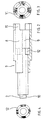
- the ends of the bands 3 and 4 are arranged on an outer bushing 8 and an inner bushing 9 of the tensioning and locking mechanism 7 and there, for example, also welded by means of a laser.
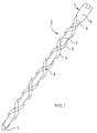
- the oppositely wound bands 3 and 4 overlap at contact surfaces 6, wherein the mutually facing surfaces of the bands 3 and 4 are formed so that there is a non-positive and frictional fixation, which stabilizes the entire intramedullary nail 1.
- the outer sleeve 8 and the inner sleeve 9 have mutual detents and are set by a thread 10 on the end of the nail core 2 and in the inner sleeve 9 on this rotatable.
- a significantly higher number of turns of the inner band 3 as well as the outer band 4 so that there is a considerable higher number of common contact surfaces 6 between the bands 3 and 4, and thus an extremely enlarged Stiffness of the intramedullary nail 1 and an associated optimized fixation of a fracture is present.
- FIGS. 2 to 4 also show only basic functional examples of the clamping and locking mechanism 7 and its key teeth 11 for attaching a mounting aid, not shown, and a section through a réelleverrastung 12 of the inner sleeve 9 and outer sleeve. 8
- Fig. 5 Also shown only as an example embodiment also has a significantly higher number of turns in a practical embodiment and here only a single formed by the head piece 5 tip from oppositely wound band whose inner windings form the inner band 3 and the outer windings the outer band 4.
- the subject nail core 2 is here completely reduced to the tensioning and closing mechanism 7 or is replaced by a free air space. Also, this version allows an outward force-free clamping of the intramedullary nail, as with all other versions mentioned above, without mechanical restoring forces would have to be absorbed by a bone or introduced into this.
Landscapes
- Health & Medical Sciences (AREA)
- Orthopedic Medicine & Surgery (AREA)
- Surgery (AREA)
- Life Sciences & Earth Sciences (AREA)
- Heart & Thoracic Surgery (AREA)
- Animal Behavior & Ethology (AREA)
- Engineering & Computer Science (AREA)
- Biomedical Technology (AREA)
- Neurology (AREA)
- Medical Informatics (AREA)
- Molecular Biology (AREA)
- Nuclear Medicine, Radiotherapy & Molecular Imaging (AREA)
- General Health & Medical Sciences (AREA)
- Public Health (AREA)
- Veterinary Medicine (AREA)
- Surgical Instruments (AREA)
- Transplanting Machines (AREA)
- Prostheses (AREA)
Claims (19)
- Clou médullaire, en particulier pour la réduction fermée d'une fracture d'un os long par insertion dans un alésage ménagé dans son creux médullaire, le clou médullaire (1) présentant une âme (2) de clou et un ruban (4) enroulé autour de l'âme (2) du clou,
caractérisé en ce que
une pièce de tête (5) à laquelle le début du ruban (4) est fixé est prévue dans la partie avant du clou médullaire (1), en ce qu'à son extrémité, le ruban (4) est fixé sans pouvoir tourner autour de l'âme (2) du clou dans sa partie arrière et en que lorsqu'il est tourné dans le sens contraire de son sens d'enroulement, il agrandit le contour radial du clou médullaire (1). - Clou médullaire selon la revendication 1, caractérisé en ce que le début d'un autre ruban intérieur (3) enroulé autour du clou médullaire (2) en dessous du ruban (4), dont l'extrémité est fixée de manière à ne pas pouvoir tourner autour de l'âme (2) du clou dans sa partie arrière tandis que lorsqu'il est tourné dans le sens opposé au sens d'enroulement, il repose sur le ruban extérieur (4) dans la zone des surfaces de contact (6) communes et stabilise le clou médullaire (1), est fixé dans la partie avant de l'âme (2) du clou.
- Clou médullaire selon la revendication 2, caractérisé en ce que les rubans (3; 4) sont enroulés dans le même sens ou dans des sens opposés autour de l'âme (2) du clou.
- Clou médullaire selon les revendications 2 ou 3, caractérisé en ce que deux ou plusieurs rubans (3; 4) sont enroulés plusieurs fois dans le même sens d'enroulement autour de l'âme (2) du clou.
- Clou médullaire selon l'une des revendications 2 à 4, caractérisé en ce que la surface située radialement à l'extérieur du ruban intérieur (3) et la surface située radialement à l'intérieur du ruban extérieur (4) sont configurées comme surfaces fonctionnelles opposées qui, en tant que surfaces (6) de contact communes, forment par une liaison en correspondance mécanique et par frottement des points de stabilisation du clou médullaire (1) inséré et serré dans un alésage de passage ménagé dans l'os.
- Clou médullaire selon l'une des revendications 2 à 5, caractérisé en ce que le ruban extérieur (4) et/ou le ruban intérieur (3) sont fixés avec précontrainte sur l'âme (2) du clou non monté et en ce que l'extrémité arrière de chaque ruban est verrouillée sur l'extrémité de l'autre ruban (3; 4).
- Clou médullaire selon l'une des revendications 2 à 6, caractérisé en ce que le ruban extérieur (4) déroulé dans le sens opposé au sens d'enroulement est configuré de telle sorte qu'il repose sur le contour intérieur de l'espace médullaire d'un os long.
- Clou médullaire selon l'une des revendications 2 à 7, caractérisé en ce que le ruban intérieur (3) et/ou le ruban extérieur (4) ont des largeurs et/ou des épaisseurs différentes dans différentes parties de l'âme (2) du clou.
- Clou médullaire selon l'une des revendications 2 à 8, caractérisé en ce que le ruban extérieur (4) est configuré de telle sorte que lorsqu'il est tourné dans le sens opposé au sens d'enroulement, il repose d'abord dans la zone de la pièce de tête (5) du clou médullaire (1) sur le contour intérieur de l'os et lorsqu'il continue de tourner, il repose d'abord sur la partie centrale de l'os long et ensuite sur la partie terminale du clou médullaire (1).
- Clou médullaire selon l'une des revendications 2 à 9, caractérisé en ce que dans la partie d'extrémité du clou médullaire (1), le ruban intérieur (3) est fixé sur une douille intérieure (9) qui peut tourner autour de l'âme (2) du clou et en ce que le ruban extérieur (4) est fixé sur une douille extérieure (8) qui peut également tourner autour de l'âme (2) du clou, les deux douilles (8; 9) présentant des encliquetages ou des surfaces d'encliquetage qui peuvent être encliquetées ou bloquées l'une sur l'autre et/ou sur l'âme (2) du clou par un mécanisme de serrage et de fermeture.
- Clou médullaire selon la revendication 10, caractérisé en ce qu'il présente un accessoire de montage qui peut en être libéré et qui présente des dispositifs d'actionnement du mécanisme de serrage et de fermeture.
- Clou médullaire selon l'une des revendications précédentes, caractérisé en ce qu'il présente sur sa partie avant ou sa partie arrière des surfaces de contact destinées à placer d'autres dispositifs mécaniques de stabilisation des fragments d'os.
- Clou médullaire selon l'une des revendications 10 à 12, caractérisé en ce que l'extrémité de l'âme (2) du clou est dotée d'un filet (10) sur lequel la douille intérieure (9) est vissée de manière à pouvoir tourner.
- Clou médullaire selon l'une des revendications 10 à 13, caractérisé en ce que l'âme (2) du clou est creuse et est traversée par un arbre et/ou une douille à l'extrémité avant desquels le début du ruban (3; 4) est fixé et en ce qu'un mécanisme correspondant de serrage et de fermeture est disposé à l'extrémité arrière du clou médullaire (1).
- Clou médullaire selon la revendication 14, caractérisé en ce que dans la partie avant de l'âme (2) du clou est fixé un ruban extérieur (4) autre que dans la partie arrière du clou médullaire (1) et en ce que les deux rubans (4) se rapprochent l'un de l'autre et s'étendent dans le même plan dans les espaces libres respectifs de l'autre ruban jusqu'à l'autre extrémité respective de l'âme (2) du clou.
- Clou médullaire selon l'une des revendications précédentes, caractérisé en ce qu'il est rectiligne ou cintré.
- Clou médullaire selon l'une des revendications précédentes, caractérisé en ce que l'âme (2) du clou est réalisée en plusieurs pièces et en ce que les pièces peuvent tourner les unes par rapport aux autres.
- Clou médullaire selon l'une des revendications 2 à 17, caractérisé en ce que deux rubans (3; 4) enroulés l'un sur l'autre sont reliés l'un à l'autre à leur extrémité avant ou en ce qu'un ruban est réalisé en une seule pièce et est enroulé dans des sens opposés autour de l'âme (2) du clou depuis son extrémité avant, et en ce que cette âme (2) de clou est plus courte et s'étend uniquement sur une partie en direction de l'extrémité avant du clou médullaire (1).
- Clou médullaire selon la revendication 18, caractérisé en ce que l'âme (2) du clou est réduite jusqu'au mécanisme (7) de serrage et de fermeture.
Priority Applications (1)
| Application Number | Priority Date | Filing Date | Title |
|---|---|---|---|
| PL05848257T PL1827272T3 (pl) | 2004-12-23 | 2005-12-02 | Gwóźdź śródszpikowy |
Applications Claiming Priority (2)
| Application Number | Priority Date | Filing Date | Title |
|---|---|---|---|
| DE102004063396A DE102004063396B4 (de) | 2004-12-23 | 2004-12-23 | Marknagel |
| PCT/DE2005/002186 WO2006066536A1 (fr) | 2004-12-23 | 2005-12-02 | Clou centromedullaire |
Publications (2)
| Publication Number | Publication Date |
|---|---|
| EP1827272A1 EP1827272A1 (fr) | 2007-09-05 |
| EP1827272B1 true EP1827272B1 (fr) | 2008-04-02 |
Family
ID=36001845
Family Applications (1)
| Application Number | Title | Priority Date | Filing Date |
|---|---|---|---|
| EP05848257A Not-in-force EP1827272B1 (fr) | 2004-12-23 | 2005-12-02 | Clou intramédullaire |
Country Status (7)
| Country | Link |
|---|---|
| US (1) | US20060142764A1 (fr) |
| EP (1) | EP1827272B1 (fr) |
| AT (1) | ATE390892T1 (fr) |
| DE (2) | DE102004063396B4 (fr) |
| ES (1) | ES2306283T3 (fr) |
| PL (1) | PL1827272T3 (fr) |
| WO (1) | WO2006066536A1 (fr) |
Cited By (3)
| Publication number | Priority date | Publication date | Assignee | Title |
|---|---|---|---|---|
| EP2722015A1 (fr) | 2012-10-19 | 2014-04-23 | Rapido Med GmbH | Clou intramédullaire |
| EP2722016A1 (fr) | 2012-10-19 | 2014-04-23 | Rapido Med GmbH | Chapiteau pour l'extrémité proximale d'un clou médullaire |
| DE102014101411A1 (de) | 2014-02-05 | 2015-08-06 | CREADO medtec GmbH | Anordnung für die Innenstabilisierung und/oder -fixierung eines langgestreckten Hohlkörpers sowie Vorrichtung zum Betätigen dieser |
Families Citing this family (11)
| Publication number | Priority date | Publication date | Assignee | Title |
|---|---|---|---|---|
| BR0116998B1 (pt) * | 2001-05-03 | 2010-07-13 | dispositivo osteossintético. | |
| KR101926339B1 (ko) | 2010-09-09 | 2019-03-07 | 신세스 게엠바하 | 수술용 네일 |
| DE102018005690A1 (de) * | 2018-02-13 | 2019-08-14 | OMEGA salvation UG (haftungsbeschränkt) | Flexibler Doppelhelix Marknagel |
| DE202020002112U1 (de) | 2020-05-13 | 2020-06-09 | Manssur Ali Arbabian | Expansionsnagel |
| CN113262030A (zh) * | 2021-06-22 | 2021-08-17 | 吉林大学 | 一种儿童子母弹性髓内钉 |
| DE202021106260U1 (de) | 2021-11-16 | 2023-02-27 | Jabez Medical GmbH & Co. KG | Zweiteiliger Marknagel sowie Nagelkern hierfür |
| DE102021129927A1 (de) | 2021-11-16 | 2023-05-17 | Jabez Medical GmbH & Co. KG | Zweiteiliger Marknagel sowie Nagelkern hierfür |
| DE202022104343U1 (de) | 2022-07-30 | 2023-11-07 | Jabez Medical GmbH & Co. KG | Vorrichtung zum Betätigen eines Marknagels, umfassend ein Gewindeelement zum Anschluss eines Marknagels |
| DE202022104342U1 (de) | 2022-07-30 | 2023-11-07 | Jabez Medical GmbH & Co. KG | Vorrichtung zum Betätigen eines Marknagels, umfassend ein Adapterstück, Set zur Bereitstellung einer solchen Vorrichtung, Adapterstück, sowie Adapterset |
| DE102022119168A1 (de) | 2022-07-30 | 2024-02-01 | Jabez Medical GmbH & Co. KG | Vorrichtung zum Betätigen eines Marknagels, umfassend ein Adapterstück, Set zur Bereitstellung einer solchen Vorrichtung, Adapterstück, sowie Adapterset |
| DE102022119169A1 (de) | 2022-07-30 | 2024-02-01 | Jabez Medical GmbH & Co. KG | Vorrichtung zum Betätigen eines Marknagels, umfassend ein Gewindeelement zum Anschluss eines Marknagels |
Family Cites Families (12)
| Publication number | Priority date | Publication date | Assignee | Title |
|---|---|---|---|---|
| US1788270A (en) * | 1928-05-07 | 1931-01-06 | Baranoff Harry | Expansion anchoring device |
| US2538601A (en) * | 1944-08-17 | 1951-01-16 | Rawiplug Company Ltd | Expanding fastener |
| DE2825719A1 (de) * | 1978-06-12 | 1979-12-13 | Kraus Werner | Zusatzvorrichtung zum anbringen einer aufnehmerspule und elektrodenanschluessen an einem osteosyntheseimplantat |
| DE2742741A1 (de) * | 1977-09-22 | 1979-04-05 | Kraus Werner | Zusatzvorrichtung zum anbringen von einer aufnehmerspule und elektrodenanschluessen an einem osteosyntheseimplantat |
| DE3835682A1 (de) * | 1988-10-20 | 1990-04-26 | Labitzke Reiner Prof Dr Med Ha | Vorrichtung zur stabilisierung von roehrenknochenbruechen sowie von gelenken |
| DD293485A5 (de) * | 1990-04-10 | 1991-09-05 | Uwe Fuhrmann,De | Intramedullaere osteosynthesespindel |
| SE506699C2 (sv) * | 1996-06-26 | 1998-02-02 | Hans Agrell | Anordning för kvarhållning av stödspikar i ben hos människor och djur |
| AT405127B (de) * | 1996-09-05 | 1999-05-25 | Karl Dr Laminger | Wendeldraht |
| EP0913129B1 (fr) * | 1996-09-05 | 2003-08-27 | Laminger, Karl, Dr.med. | Fil hélicoidal ostéosynthétique |
| DE19731298A1 (de) * | 1996-12-30 | 1999-11-18 | Basheir Madhoon | Nagelsystem für die intramedulläre Osteosynthese bei Schaftfrakturen aller Art und Totalendprothesen |
| US6468309B1 (en) * | 2000-10-05 | 2002-10-22 | Cleveland Clinic Foundation | Method and apparatus for stabilizing adjacent bones |
| US6986771B2 (en) * | 2003-05-23 | 2006-01-17 | Globus Medical, Inc. | Spine stabilization system |
-
2004
- 2004-12-23 DE DE102004063396A patent/DE102004063396B4/de not_active Expired - Fee Related
-
2005
- 2005-12-02 EP EP05848257A patent/EP1827272B1/fr not_active Not-in-force
- 2005-12-02 PL PL05848257T patent/PL1827272T3/pl unknown
- 2005-12-02 WO PCT/DE2005/002186 patent/WO2006066536A1/fr active IP Right Grant
- 2005-12-02 AT AT05848257T patent/ATE390892T1/de active
- 2005-12-02 ES ES05848257T patent/ES2306283T3/es active Active
- 2005-12-02 DE DE502005003598T patent/DE502005003598D1/de active Active
- 2005-12-23 US US11/318,197 patent/US20060142764A1/en not_active Abandoned
Cited By (6)
| Publication number | Priority date | Publication date | Assignee | Title |
|---|---|---|---|---|
| EP2722015A1 (fr) | 2012-10-19 | 2014-04-23 | Rapido Med GmbH | Clou intramédullaire |
| EP2722016A1 (fr) | 2012-10-19 | 2014-04-23 | Rapido Med GmbH | Chapiteau pour l'extrémité proximale d'un clou médullaire |
| WO2014060578A1 (fr) * | 2012-10-19 | 2014-04-24 | Rapido Med Gmbh | Embout pour l'extrémité proximale d'un clou médullaire |
| WO2014060576A1 (fr) | 2012-10-19 | 2014-04-24 | Rapido Med Gmbh | Clou intramédullaire |
| DE102014101411A1 (de) | 2014-02-05 | 2015-08-06 | CREADO medtec GmbH | Anordnung für die Innenstabilisierung und/oder -fixierung eines langgestreckten Hohlkörpers sowie Vorrichtung zum Betätigen dieser |
| WO2015117996A1 (fr) | 2014-02-05 | 2015-08-13 | CREADO medtec GmbH | Agencement de stabilisation et/ou fixation intérieure d'un corps creux allongé et dispositif d'actionnement de cet agencement |
Also Published As
| Publication number | Publication date |
|---|---|
| PL1827272T3 (pl) | 2008-10-31 |
| DE502005003598D1 (de) | 2008-05-15 |
| DE102004063396A1 (de) | 2006-07-13 |
| EP1827272A1 (fr) | 2007-09-05 |
| WO2006066536A1 (fr) | 2006-06-29 |
| DE102004063396B4 (de) | 2006-11-02 |
| US20060142764A1 (en) | 2006-06-29 |
| ATE390892T1 (de) | 2008-04-15 |
| ES2306283T3 (es) | 2008-11-01 |
Similar Documents
| Publication | Publication Date | Title |
|---|---|---|
| EP1827272B1 (fr) | Clou intramédullaire | |
| EP2263584B1 (fr) | Clou intramédullaire avec vis de blocage | |
| WO2014060576A1 (fr) | Clou intramédullaire | |
| DE60014042T2 (de) | Axialer äusserer Fixateur | |
| DE10157814B4 (de) | Verschlußeinrichtung zum Sichern eines stabförmigen Elements in einem mit einem Schaft verbundenen Halteelement | |
| DE4212635C2 (de) | Mit Draht befestigbare Knochen-Platte zur inneren Festlegung eines Bruches | |
| EP2736430B1 (fr) | Dispositif pouvant être implanté | |
| EP2705802A2 (fr) | Système d'implant destiné à la stabilisation d'os | |
| EP2722016A1 (fr) | Chapiteau pour l'extrémité proximale d'un clou médullaire | |
| DE1055750B (de) | Chirurgische Schraubverbindung zur Verwendung bei Schenkelhalsbruechen | |
| DE202005019277U1 (de) | Knochenplatte mit wenigstens zwei Langlöchern und Knochenplattensystem | |
| WO2015117996A1 (fr) | Agencement de stabilisation et/ou fixation intérieure d'un corps creux allongé et dispositif d'actionnement de cet agencement | |
| WO2023088517A1 (fr) | Clou intramédullaire en deux parties et noyau de clou correspondant | |
| WO1999065413A1 (fr) | Element de pression pour exercer une pression sur une surface | |
| DE102011106653A1 (de) | Verankerungselement mit funktionalem Schaft und modulares Veranderungssystem | |
| EP1053718A1 (fr) | Clou de verrouillage pour le traitement des fractures de la tige fémorale | |
| EP0779795B1 (fr) | Dispositif d'osteosynthese externe | |
| DE102017124734B4 (de) | Polyaxialschraube | |
| DE102011111403A1 (de) | Tulpenkopfschraube zur Repositionierung von Wirbelkörpern | |
| DE102007029090A1 (de) | Vorrichtung zur Osteosynthese gelenknaher Knochenfrakturen | |
| DE102020003247A1 (de) | Modulare Osteosynthesevorrichtung für Wirbel | |
| EP0303773A2 (fr) | Dispositif de protection des vertèbres de la colonne vertébrale humaine | |
| DE102007014730A1 (de) | Manipulator für Rundmaterial, insbesondere für einen Kirschnerdraht | |
| DE3515678A1 (de) | Vorrichtung zum befestigen und spannen von fixateur externe-bauteilen | |
| EP2934355B1 (fr) | Clou intramedullaire à verrouillage comprenant des trous pour un fil de guidage |
Legal Events
| Date | Code | Title | Description |
|---|---|---|---|
| PUAI | Public reference made under article 153(3) epc to a published international application that has entered the european phase |
Free format text: ORIGINAL CODE: 0009012 |
|
| 17P | Request for examination filed |
Effective date: 20070711 |
|
| AK | Designated contracting states |
Kind code of ref document: A1 Designated state(s): AT BE BG CH CY CZ DE DK EE ES FI FR GB GR HU IE IS IT LI LT LU LV MC NL PL PT RO SE SI SK TR |
|
| GRAP | Despatch of communication of intention to grant a patent |
Free format text: ORIGINAL CODE: EPIDOSNIGR1 |
|
| RTI1 | Title (correction) |
Free format text: INTRAMEDULLARY NAIL |
|
| RIN1 | Information on inventor provided before grant (corrected) |
Inventor name: ZILLERT, MARKUS |
|
| GRAS | Grant fee paid |
Free format text: ORIGINAL CODE: EPIDOSNIGR3 |
|
| GRAA | (expected) grant |
Free format text: ORIGINAL CODE: 0009210 |
|
| AK | Designated contracting states |
Kind code of ref document: B1 Designated state(s): AT BE BG CH CY CZ DE DK EE ES FI FR GB GR HU IE IS IT LI LT LU LV MC NL PL PT RO SE SI SK TR |
|
| DAX | Request for extension of the european patent (deleted) | ||
| REG | Reference to a national code |
Ref country code: GB Ref legal event code: FG4D Free format text: NOT ENGLISH |
|
| REG | Reference to a national code |
Ref country code: IE Ref legal event code: FG4D Free format text: LANGUAGE OF EP DOCUMENT: GERMAN Ref country code: CH Ref legal event code: EP |
|
| REF | Corresponds to: |
Ref document number: 502005003598 Country of ref document: DE Date of ref document: 20080515 Kind code of ref document: P |
|
| RIN2 | Information on inventor provided after grant (corrected) |
Inventor name: ZIELSDORF, MICHAEL Inventor name: ZILLERT, MARKUS |
|
| REG | Reference to a national code |
Ref country code: RO Ref legal event code: EPE |
|
| PG25 | Lapsed in a contracting state [announced via postgrant information from national office to epo] |
Ref country code: SI Free format text: LAPSE BECAUSE OF FAILURE TO SUBMIT A TRANSLATION OF THE DESCRIPTION OR TO PAY THE FEE WITHIN THE PRESCRIBED TIME-LIMIT Effective date: 20080402 |
|
| REG | Reference to a national code |
Ref country code: IE Ref legal event code: FD4D |
|
| PG25 | Lapsed in a contracting state [announced via postgrant information from national office to epo] |
Ref country code: BG Free format text: LAPSE BECAUSE OF FAILURE TO SUBMIT A TRANSLATION OF THE DESCRIPTION OR TO PAY THE FEE WITHIN THE PRESCRIBED TIME-LIMIT Effective date: 20080702 Ref country code: FI Free format text: LAPSE BECAUSE OF FAILURE TO SUBMIT A TRANSLATION OF THE DESCRIPTION OR TO PAY THE FEE WITHIN THE PRESCRIBED TIME-LIMIT Effective date: 20080402 Ref country code: PT Free format text: LAPSE BECAUSE OF FAILURE TO SUBMIT A TRANSLATION OF THE DESCRIPTION OR TO PAY THE FEE WITHIN THE PRESCRIBED TIME-LIMIT Effective date: 20080904 |
|
| REG | Reference to a national code |
Ref country code: PL Ref legal event code: T3 |
|
| REG | Reference to a national code |
Ref country code: ES Ref legal event code: FG2A Ref document number: 2306283 Country of ref document: ES Kind code of ref document: T3 |
|
| PG25 | Lapsed in a contracting state [announced via postgrant information from national office to epo] |
Ref country code: LV Free format text: LAPSE BECAUSE OF FAILURE TO SUBMIT A TRANSLATION OF THE DESCRIPTION OR TO PAY THE FEE WITHIN THE PRESCRIBED TIME-LIMIT Effective date: 20080402 |
|
| PG25 | Lapsed in a contracting state [announced via postgrant information from national office to epo] |
Ref country code: IS Free format text: LAPSE BECAUSE OF FAILURE TO SUBMIT A TRANSLATION OF THE DESCRIPTION OR TO PAY THE FEE WITHIN THE PRESCRIBED TIME-LIMIT Effective date: 20080802 |
|
| ET | Fr: translation filed | ||
| PG25 | Lapsed in a contracting state [announced via postgrant information from national office to epo] |
Ref country code: DK Free format text: LAPSE BECAUSE OF FAILURE TO SUBMIT A TRANSLATION OF THE DESCRIPTION OR TO PAY THE FEE WITHIN THE PRESCRIBED TIME-LIMIT Effective date: 20080402 Ref country code: SE Free format text: LAPSE BECAUSE OF FAILURE TO SUBMIT A TRANSLATION OF THE DESCRIPTION OR TO PAY THE FEE WITHIN THE PRESCRIBED TIME-LIMIT Effective date: 20080702 Ref country code: CZ Free format text: LAPSE BECAUSE OF FAILURE TO SUBMIT A TRANSLATION OF THE DESCRIPTION OR TO PAY THE FEE WITHIN THE PRESCRIBED TIME-LIMIT Effective date: 20080402 Ref country code: IE Free format text: LAPSE BECAUSE OF FAILURE TO SUBMIT A TRANSLATION OF THE DESCRIPTION OR TO PAY THE FEE WITHIN THE PRESCRIBED TIME-LIMIT Effective date: 20080402 Ref country code: LT Free format text: LAPSE BECAUSE OF FAILURE TO SUBMIT A TRANSLATION OF THE DESCRIPTION OR TO PAY THE FEE WITHIN THE PRESCRIBED TIME-LIMIT Effective date: 20080402 |
|
| PLBE | No opposition filed within time limit |
Free format text: ORIGINAL CODE: 0009261 |
|
| STAA | Information on the status of an ep patent application or granted ep patent |
Free format text: STATUS: NO OPPOSITION FILED WITHIN TIME LIMIT |
|
| PG25 | Lapsed in a contracting state [announced via postgrant information from national office to epo] |
Ref country code: SK Free format text: LAPSE BECAUSE OF FAILURE TO SUBMIT A TRANSLATION OF THE DESCRIPTION OR TO PAY THE FEE WITHIN THE PRESCRIBED TIME-LIMIT Effective date: 20080402 |
|
| 26N | No opposition filed |
Effective date: 20090106 |
|
| PG25 | Lapsed in a contracting state [announced via postgrant information from national office to epo] |
Ref country code: EE Free format text: LAPSE BECAUSE OF FAILURE TO SUBMIT A TRANSLATION OF THE DESCRIPTION OR TO PAY THE FEE WITHIN THE PRESCRIBED TIME-LIMIT Effective date: 20080402 |
|
| PGFP | Annual fee paid to national office [announced via postgrant information from national office to epo] |
Ref country code: RO Payment date: 20081230 Year of fee payment: 4 |
|
| PG25 | Lapsed in a contracting state [announced via postgrant information from national office to epo] |
Ref country code: MC Free format text: LAPSE BECAUSE OF NON-PAYMENT OF DUE FEES Effective date: 20081231 |
|
| PG25 | Lapsed in a contracting state [announced via postgrant information from national office to epo] |
Ref country code: CY Free format text: LAPSE BECAUSE OF FAILURE TO SUBMIT A TRANSLATION OF THE DESCRIPTION OR TO PAY THE FEE WITHIN THE PRESCRIBED TIME-LIMIT Effective date: 20080402 |
|
| PG25 | Lapsed in a contracting state [announced via postgrant information from national office to epo] |
Ref country code: HU Free format text: LAPSE BECAUSE OF FAILURE TO SUBMIT A TRANSLATION OF THE DESCRIPTION OR TO PAY THE FEE WITHIN THE PRESCRIBED TIME-LIMIT Effective date: 20081003 Ref country code: LU Free format text: LAPSE BECAUSE OF NON-PAYMENT OF DUE FEES Effective date: 20081202 |
|
| PG25 | Lapsed in a contracting state [announced via postgrant information from national office to epo] |
Ref country code: GR Free format text: LAPSE BECAUSE OF FAILURE TO SUBMIT A TRANSLATION OF THE DESCRIPTION OR TO PAY THE FEE WITHIN THE PRESCRIBED TIME-LIMIT Effective date: 20080703 |
|
| PG25 | Lapsed in a contracting state [announced via postgrant information from national office to epo] |
Ref country code: RO Free format text: LAPSE BECAUSE OF NON-PAYMENT OF DUE FEES Effective date: 20091202 |
|
| REG | Reference to a national code |
Ref country code: CH Ref legal event code: NV Representative=s name: ISLER & PEDRAZZINI AG Ref country code: CH Ref legal event code: PUE Owner name: RAPIDO R&D GMBH Free format text: ZIELSDORF, MICHAEL#IM BIEGEL 9#34516 VOEHL (DE) -TRANSFER TO- RAPIDO R&D GMBH#BERLINER STR. 10#34560 FRITZLAR (DE) Ref country code: CH Ref legal event code: PUE Owner name: EYSERT - BERATUNG UND MANAGEMENT GMBH Free format text: RAPIDO R&D GMBH#BERLINER STR. 10#34560 FRITZLAR (DE) -TRANSFER TO- EYSERT - BERATUNG UND MANAGEMENT GMBH#CHRISTIAN-FLEISCHHAUER-STR. 18#34549 EDERTAL (DE) |
|
| REG | Reference to a national code |
Ref country code: NL Ref legal event code: SD Effective date: 20120407 |
|
| BECA | Be: change of holder's address |
Owner name: EYSERT-BERATUNG UND MANAGEMENT G.M.B.H. Effective date: 20120704 Owner name: CHRISTIAN-FLEISCHHAUER-STRASSE 18, D-34549 EDERTAL Effective date: 20120704 |
|
| BECH | Be: change of holder |
Owner name: EYSERT-BERATUNG UND MANAGEMENT G.M.B.H. Effective date: 20120704 |
|
| REG | Reference to a national code |
Ref country code: ES Ref legal event code: PC2A Owner name: EYSERT-BERATUNG UND MANAGEMENT GMBH Effective date: 20120807 |
|
| REG | Reference to a national code |
Ref country code: GB Ref legal event code: 732E Free format text: REGISTERED BETWEEN 20120809 AND 20120815 |
|
| REG | Reference to a national code |
Ref country code: FR Ref legal event code: TP Owner name: EYSERT - BERATUNG UND MANAGEMENT GMBH, DE Effective date: 20130627 |
|
| REG | Reference to a national code |
Ref country code: AT Ref legal event code: PC Ref document number: 390892 Country of ref document: AT Kind code of ref document: T Owner name: EYSERT - BERATUNG UND MANAGEMENT GMBH, DE Effective date: 20130719 |
|
| REG | Reference to a national code |
Ref country code: CH Ref legal event code: PUE Owner name: RAPIDO MED GMBH, DE Free format text: FORMER OWNER: EYSERT - BERATUNG UND MANAGEMENT GMBH, DE |
|
| REG | Reference to a national code |
Ref country code: NL Ref legal event code: SD Effective date: 20131121 |
|
| REG | Reference to a national code |
Ref country code: GB Ref legal event code: 732E Free format text: REGISTERED BETWEEN 20131230 AND 20131231 |
|
| PGFP | Annual fee paid to national office [announced via postgrant information from national office to epo] |
Ref country code: AT Payment date: 20131216 Year of fee payment: 9 Ref country code: GB Payment date: 20131217 Year of fee payment: 9 Ref country code: CH Payment date: 20131218 Year of fee payment: 9 |
|
| PGFP | Annual fee paid to national office [announced via postgrant information from national office to epo] |
Ref country code: FR Payment date: 20131213 Year of fee payment: 9 Ref country code: PL Payment date: 20131120 Year of fee payment: 9 Ref country code: IT Payment date: 20131217 Year of fee payment: 9 Ref country code: ES Payment date: 20131216 Year of fee payment: 9 Ref country code: NL Payment date: 20131216 Year of fee payment: 9 Ref country code: TR Payment date: 20131120 Year of fee payment: 9 |
|
| PGFP | Annual fee paid to national office [announced via postgrant information from national office to epo] |
Ref country code: BE Payment date: 20131216 Year of fee payment: 9 |
|
| REG | Reference to a national code |
Ref country code: AT Ref legal event code: PC Ref document number: 390892 Country of ref document: AT Kind code of ref document: T Owner name: RAPIDO MED GMBH, DE Effective date: 20140904 |
|
| PGFP | Annual fee paid to national office [announced via postgrant information from national office to epo] |
Ref country code: DE Payment date: 20141223 Year of fee payment: 10 |
|
| PG25 | Lapsed in a contracting state [announced via postgrant information from national office to epo] |
Ref country code: BE Free format text: LAPSE BECAUSE OF NON-PAYMENT OF DUE FEES Effective date: 20141231 |
|
| REG | Reference to a national code |
Ref country code: NL Ref legal event code: V1 Effective date: 20150701 |
|
| REG | Reference to a national code |
Ref country code: NL Ref legal event code: V1 Effective date: 20150701 |
|
| REG | Reference to a national code |
Ref country code: CH Ref legal event code: PL |
|
| REG | Reference to a national code |
Ref country code: AT Ref legal event code: MM01 Ref document number: 390892 Country of ref document: AT Kind code of ref document: T Effective date: 20141202 |
|
| GBPC | Gb: european patent ceased through non-payment of renewal fee |
Effective date: 20141202 |
|
| REG | Reference to a national code |
Ref country code: FR Ref legal event code: ST Effective date: 20150831 |
|
| PG25 | Lapsed in a contracting state [announced via postgrant information from national office to epo] |
Ref country code: NL Free format text: LAPSE BECAUSE OF NON-PAYMENT OF DUE FEES Effective date: 20150701 |
|
| PG25 | Lapsed in a contracting state [announced via postgrant information from national office to epo] |
Ref country code: GB Free format text: LAPSE BECAUSE OF NON-PAYMENT OF DUE FEES Effective date: 20141202 Ref country code: LI Free format text: LAPSE BECAUSE OF NON-PAYMENT OF DUE FEES Effective date: 20141231 Ref country code: CH Free format text: LAPSE BECAUSE OF NON-PAYMENT OF DUE FEES Effective date: 20141231 |
|
| PG25 | Lapsed in a contracting state [announced via postgrant information from national office to epo] |
Ref country code: FR Free format text: LAPSE BECAUSE OF NON-PAYMENT OF DUE FEES Effective date: 20141231 Ref country code: AT Free format text: LAPSE BECAUSE OF NON-PAYMENT OF DUE FEES Effective date: 20141202 |
|
| PG25 | Lapsed in a contracting state [announced via postgrant information from national office to epo] |
Ref country code: IT Free format text: LAPSE BECAUSE OF NON-PAYMENT OF DUE FEES Effective date: 20141202 |
|
| REG | Reference to a national code |
Ref country code: ES Ref legal event code: FD2A Effective date: 20160530 |
|
| PG25 | Lapsed in a contracting state [announced via postgrant information from national office to epo] |
Ref country code: PL Free format text: LAPSE BECAUSE OF NON-PAYMENT OF DUE FEES Effective date: 20141202 |
|
| REG | Reference to a national code |
Ref country code: DE Ref legal event code: R119 Ref document number: 502005003598 Country of ref document: DE |
|
| PG25 | Lapsed in a contracting state [announced via postgrant information from national office to epo] |
Ref country code: ES Free format text: LAPSE BECAUSE OF NON-PAYMENT OF DUE FEES Effective date: 20141203 |
|
| PG25 | Lapsed in a contracting state [announced via postgrant information from national office to epo] |
Ref country code: DE Free format text: LAPSE BECAUSE OF NON-PAYMENT OF DUE FEES Effective date: 20160701 |
|
| PG25 | Lapsed in a contracting state [announced via postgrant information from national office to epo] |
Ref country code: TR Free format text: LAPSE BECAUSE OF NON-PAYMENT OF DUE FEES Effective date: 20141202 |