EP1800935A1 - Vorrichtung und Verfahren der Steuerung für elektrisch angetriebenen Gabelstapler - Google Patents
Vorrichtung und Verfahren der Steuerung für elektrisch angetriebenen Gabelstapler Download PDFInfo
- Publication number
- EP1800935A1 EP1800935A1 EP20060026802 EP06026802A EP1800935A1 EP 1800935 A1 EP1800935 A1 EP 1800935A1 EP 20060026802 EP20060026802 EP 20060026802 EP 06026802 A EP06026802 A EP 06026802A EP 1800935 A1 EP1800935 A1 EP 1800935A1
- Authority
- EP
- European Patent Office
- Prior art keywords
- actuation unit
- input
- traveling
- sensing means
- zero speed
- Prior art date
- Legal status (The legal status is an assumption and is not a legal conclusion. Google has not performed a legal analysis and makes no representation as to the accuracy of the status listed.)
- Granted
Links
Images


Classifications
-
- B—PERFORMING OPERATIONS; TRANSPORTING
- B60—VEHICLES IN GENERAL
- B60L—PROPULSION OF ELECTRICALLY-PROPELLED VEHICLES; SUPPLYING ELECTRIC POWER FOR AUXILIARY EQUIPMENT OF ELECTRICALLY-PROPELLED VEHICLES; ELECTRODYNAMIC BRAKE SYSTEMS FOR VEHICLES IN GENERAL; MAGNETIC SUSPENSION OR LEVITATION FOR VEHICLES; MONITORING OPERATING VARIABLES OF ELECTRICALLY-PROPELLED VEHICLES; ELECTRIC SAFETY DEVICES FOR ELECTRICALLY-PROPELLED VEHICLES
- B60L3/00—Electric devices on electrically-propelled vehicles for safety purposes; Monitoring operating variables, e.g. speed, deceleration or energy consumption
- B60L3/02—Dead-man's devices
-
- B—PERFORMING OPERATIONS; TRANSPORTING
- B60—VEHICLES IN GENERAL
- B60T—VEHICLE BRAKE CONTROL SYSTEMS OR PARTS THEREOF; BRAKE CONTROL SYSTEMS OR PARTS THEREOF, IN GENERAL; ARRANGEMENT OF BRAKING ELEMENTS ON VEHICLES IN GENERAL; PORTABLE DEVICES FOR PREVENTING UNWANTED MOVEMENT OF VEHICLES; VEHICLE MODIFICATIONS TO FACILITATE COOLING OF BRAKES
- B60T7/00—Brake-action initiating means
- B60T7/12—Brake-action initiating means for automatic initiation; for initiation not subject to will of driver or passenger
-
- B—PERFORMING OPERATIONS; TRANSPORTING
- B66—HOISTING; LIFTING; HAULING
- B66F—HOISTING, LIFTING, HAULING OR PUSHING, NOT OTHERWISE PROVIDED FOR, e.g. DEVICES WHICH APPLY A LIFTING OR PUSHING FORCE DIRECTLY TO THE SURFACE OF A LOAD
- B66F9/00—Devices for lifting or lowering bulky or heavy goods for loading or unloading purposes
-
- B—PERFORMING OPERATIONS; TRANSPORTING
- B66—HOISTING; LIFTING; HAULING
- B66F—HOISTING, LIFTING, HAULING OR PUSHING, NOT OTHERWISE PROVIDED FOR, e.g. DEVICES WHICH APPLY A LIFTING OR PUSHING FORCE DIRECTLY TO THE SURFACE OF A LOAD
- B66F9/00—Devices for lifting or lowering bulky or heavy goods for loading or unloading purposes
- B66F9/06—Devices for lifting or lowering bulky or heavy goods for loading or unloading purposes movable, with their loads, on wheels or the like, e.g. fork-lift trucks
- B66F9/075—Constructional features or details
- B66F9/20—Means for actuating or controlling masts, platforms, or forks
- B66F9/24—Electrical devices or systems
Definitions
- the present invention relates, in general, to a control system and method for an electric-powered forklift, more particularly, to a control system and method for an electric-powered forklift, which can automatically brake the forklift without requiring a driver to perform a manual operation.
- An electric-powered forklift is a vehicle using the electricity of a battery as a power source.
- Such an electric-powered forklift includes a travel motor for enabling the vehicle to travel, and an actuation unit motor for driving an actuation unit, such as a lift cylinder or tilt cylinder.
- the electric-powered forklift includes a travel brake unit for braking the vehicle during traveling, and a parking brake unit for keeping the vehicle in a stationary state when parked.
- the travel brake unit is a multi-plate brake that performs braking by pressing a disc installed on an axle shaft using a friction plate, and that operates when a driver steps on a brake pedal installed near a driver's seat, thus braking the vehicle during traveling.
- the parking brake unit is a band-type parking brake that performs braking by pressurizing the circumferential portion of a drum, installed on an axle shaft, using a band, and that operates when a driver operates a parking lever or the like, installed near a driver's seat, thus keeping the vehicle in a stationary state when parked.
- the conventional electric-powered forklift is disadvantageous in that, whenever traveling stops and an actuation unit is operated, the vehicle must be braked by manipulating the brake pedal or parking lever.
- the vehicle when traveling stops and goods are loaded or unloaded, the vehicle is braked by manipulating the travel brake unit or parking brake unit to stabilize the vehicle, and thereafter performs work.
- the vehicle when loading or unloading goods in an inclined place, the vehicle may be pushed downwards. Accordingly, after the travel brake unit or the parking brake unit is manipulated to brake the vehicle, work is performed. Therefore, the conventional electric-powered forklift is very inconvenient in that the travel brake pedal or parking lever must be manually manipulated whenever traveling operation stops and work is performed.
- an object of the present invention is to provide a control system and method for an electric-powered forklift, which can maximize the convenience and safety of a driver even when the vehicle is braked in order to perform work.
- the present invention provides a control system for an electric-powered forklift, the electric-powered forklift including a travel motor for driving a wheel, and an actuation unit motor for driving an actuation unit, comprising travel sensing means for sensing a traveling operation of a driver; an actuation unit sensing means for sensing an operation of the actuation unit; and a controller for controlling the travel motor in response to signals output from the travel sensing means and the actuation unit sensing means, respectively, wherein, if the actuation unit is operated when the traveling operation is not performed, the forklift is controlled by the controller so that the forklift is in a zero speed state, in which actual motion of the forklift is not allowed.
- the present invention provides a control method for an electric-powered forklift, the electric-powered forklift including a travel motor for driving a wheel, and an actuation unit motor for driving an actuation unit, comprising the steps of sensing input of a traveling signal corresponding to a traveling operation of a driver; sensing input of an actuation unit operation signal corresponding to driving of the actuation unit; and controlling the forklift so that it is in a zero speed state, in which the forklift actually stops, wherein the zero speed control step is performed when only the actuation unit operation signal is input, without the traveling signal being input.
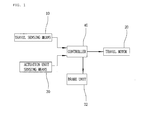
- FIG. 1 illustrates a first embodiment of a control system for an electric-powered forklift according to the present invention.
- the control system includes a travel sensing means 10 for sensing whether a vehicle is traveling.
- the travel sensing means 10 is a sensor for sensing whether a driver is pressing an accelerator pedal (not shown), and can be implemented using a rotation sensor for sensing the slope of the accelerator pedal, or a pressure sensor for sensing the distance that the accelerator pedal is pressed.
- Such a travel sensing means 10 senses that the vehicle is currently traveling by outputting a traveling signal when the driver steps on the accelerator pedal.
- the travel sensing means 10 can be implemented using a current sensor for sensing the flow of current in a travel motor 20.
- the current sensor senses the flow of current in the travel motor 20, thus sensing whether the travel motor 20 is currently being driven and the vehicle is traveling.
- the travel sensing means 10 can be implemented using a forward/backward lever position sensor for sensing the position of a forward/backward lever.
- the forward/backward lever position sensor senses the position of the forward/backward lever, which is moved to a forward position or a backward position, thus sensing whether the vehicle is currently traveling.
- control system of the present invention includes an actuation unit sensing means 30 for sensing whether an actuation unit is currently operating.
- the actuation unit sensing means 30 is implemented using a rotation sensor for sensing the rotation of the shaft of an actuation unit motor (not shown), and is operated to sense the rotation of the actuation unit motor, thus sensing whether the vehicle is currently performing work.
- the rotation sensor is implemented using a rotary encoder installed on the shaft of the actuation unit motor.
- the actuation unit sensing means 30 can be implemented using a hydraulic oil sensor for sensing the flow of hydraulic oil flowing into an actuation unit.
- the hydraulic oil sensor senses the flow of hydraulic oil, flowing into the actuation unit, thus sensing whether an actuation unit is currently operating, and consequently sensing whether the vehicle is currently performing work.
- control system of the present invention includes a controller 40 for controlling the travel motor 20 in response to signals output from the travel sensing means 10 and the actuation unit sensing means 30.
- the controller 40 is provided with a microprocessor, and is operated to determine that the vehicle has currently stopped traveling and is only performing work if a signal is input from the actuation unit sensing means 30 when no signal is input from the travel sensing means 10, thus controlling the vehicle so that the vehicle is actually in a stopped state, that is, a "zero speed" state.
- a "zero speed” state can be realized by controlling the travel motor 20, or by driving a brake unit 22.
- the brake unit in this embodiment is operated by oil pressure, and such a zero speed state is maintained by causing oil pressure to be automatically applied to the brake unit 22 by the controller 40.
- the "zero speed” state is released when a traveling signal is input from the travel sensing means 10 or when the input of a sensed signal from the actuation unit sensing means 30 is stopped. If a signal is input from the actuation unit sensing means 30 again after the "zero speed” state is released in this way, the vehicle is controlled again so that it is in the "zero speed” state. Of course, even in this case, the state in which no traveling signal is input from the travel sensing means 10 must be realized.
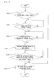
- step S101 whether a traveling signal is input from the travel sensing means 10 is sensed.
- step S103 whether an actuation unit operation signal is input from the actuation unit sensing means 30 is sensed at step S103.
- the controller 40 determines that the vehicle has currently stopped traveling and is only performing work, thus driving the brake unit 22, and consequently controlling the vehicle so that it is in a "zero-speed" state at step S105. Therefore, the vehicle can stably perform the operation of unloading or loading goods.
- the controller 40 releases the brake unit so that the vehicle is released from the zero speed state at step S109.
- the present invention can maximize the driver's convenience, unlike the prior art, which forces the driver to manually brake the vehicle.
- FIG. 3 illustrates a second embodiment of a control system for an electric-powered forklift according to a second embodiment of the present invention.
- the control system includes a controller 50 for processing signals output from a travel sensing means 10 and an actuation unit sensing means 30, the controller 50 including a timer 52.
- the timer 52 counts the time for which the input of a sensed signal is stopped when the input of the sensed signal from the actuation unit sensing means 30 is stopped.
- the controller 50 determines that the actuation unit is not currently being used, thus releasing the vehicle from the "zero speed" state.
- the preset time stored in the controller 50 is preferably about five minutes.
- Such a controller 50 according to the second embodiment of the present invention differs from that of the first embodiment only in the above-described way, and the construction and operation thereof is otherwise identical to the first embodiment. Therefore, a detailed description thereof is omitted.
- step S201 whether a traveling signal is input from the travel sensing means 10 is sensed. In this case, if no traveling signal is found to be input, whether an actuation unit operation signal is input from the actuation unit sensing means 30 is sensed at step S203.
- the controller 50 determines that the vehicle has currently stopped traveling and is only performing work, thus driving the brake unit 22, and consequently controlling the vehicle so that it is in a "zero speed" state at step S205. Accordingly, the vehicle can stably perform the operation of unloading or loading goods.
- the controller 50 releases the brake unit 22, thus immediately releasing the vehicle from the zero speed state at step S209.
- control method uses a scheme for releasing the "zero speed" state after a preset time has elapsed even if the input of the actuation unit operation signal from the actuation unit sensing means 30 is stopped, thus preventing the braked state of the vehicle from being released even when the driver of the vehicle temporarily stops the operation of the actuation unit.
- FIG. 5 illustrates a third embodiment of a control system for an electric-powered forklift according to the present invention.
- the control system according to the third embodiment further includes a wheel rotation sensing means 60 for sensing whether the wheel of the vehicle is rotating.
- the wheel rotation sensing means 60 is implemented using a rotation sensor for sensing the rotation of an axle shaft (not shown) connected to the wheel of the vehicle.
- the wheel rotation sensing means 60 can be implemented using a rotation sensor for sensing the rotation of the shaft of the travel motor 20 connected to the wheel.
- Such a wheel rotation sensing means 60 senses the rotation of the axle shaft or the travel motor 20, thus sensing whether the vehicle is currently rotating.
- the wheel rotation sensing means 60 senses whether the wheel is performing idle rotation regardless of the driving force of the travel motor 20.
- a rotary encoder is used as the rotation sensor.
- control system includes a controller 70 for controlling the travel motor 20 in response to signals output from the travel sensing means 10, the actuation unit sensing means 30 and the wheel rotation sensing means 60.
- the controller determines that the vehicle is not currently traveling and is performing work while being pushed downwards in an inclined place, thus controlling the travel motor 20.
- the travel motor 20 is controlled so that the "zero speed" state thereof is maintained by the application of predetermined reverse current. That is, when the vehicle is moved by a load while no signal is input from the travel sensing means 10, the reverse current is applied so that reversal rotary power is generated at the travel motor 20 in a reverse direction relative to the direction in which the vehicle is moved.
- the reversal rotary power can have any intensity enabling the vehicle to be maintained in the "zero speed” state.
- reverse current is applied in a reverse direction relative to that direction, thus maintaining the vehicle in the "zero speed” state. The application of such reverse current is alternately performed, thus the vehicle can be maintained in a stopped state in actuality.
- the control system can be constructed so that the brake is automatically driven if the driver does not conduct a traveling operation even during the traveling of the vehicle. That is, even during traveling, the control system can increase the convenience of the driver of the vehicle. In this case, it is preferable that, if the condition of "zero speed" is satisfied after the vehicle stops traveling, control for "zero speed" be successively started.
- the stopped state of the vehicle cannot be maintained if the actuation unit is not operated immediately after the vehicle has stopped.
- the vehicle is parked in an inclined place, there is a probability that the vehicle will move due to the load thereof, thus causing an accident.
- Such a problem can be prevented by controlling the travel motor 20 to remain in the same state as the above-described "zero speed" state even if the actuation unit is not driven for a certain period of time after the vehicle has stopped.
- Such an advantage can be easily achieved when the timer, described in the above embodiment, can be used together with the function.
- the controller 70 drives the travel motor 20 normally.
- the controller 70 determines that the actuation unit is not currently being used, and thus immediately releases the travel motor 20 from the "zero speed” state.
- the controller 70 maintains the travel motor 20 in the "zero speed” state again.
- a state in which no traveling signal is input from the travel sensing means 10 must be realized.
- step S301 whether a traveling signal is input from the travel sensing means 10 is sensed.
- step S303 whether a wheel rotation signal is input from the wheel rotation sensing means 60 is sensed. If the wheel rotation signal is found to be input as a result of the sensing, whether an actuation unit operation signal is input from the actuation unit sensing means 30 is sensed at step S305.
- the controller 70 determines that the vehicle currently stops traveling and is performing work while being pushed downwards in an inclined place, and thus controls the travel motor 20 so that it is in a "zero speed" state at step S307.
- the controller 70 immediately releases the travel motor 20 from the zero speed state at step S311.
- controller 70 senses whether the input of the actuation unit operation signal from the actuation unit sensing means 30 is stopped after the travel motor 20 has been controlled to be in the "zero speed” state at step S309.
- the controller 70 determines that the actuation unit is not currently being used, thus immediately releasing the travel motor 20 from the "zero speed" state at step S311.
- the travel motor 20 since the travel motor 20 is released from the "zero speed” state, the travel motor 20 can be freely rotated forward or backward, and thus travel forward or backward.
- the travel motor 20 is automatically maintained at the "zero speed" state to stop the vehicle, so that the vehicle can perform work while maintaining a stable state even in an inclined place.
- the vehicle automatically stops without requiring a driver to perform a manual operation, the inconvenience of forcing the driver to manipulate a travel brake unit or parking brake unit when performing work in an inclined place can be eliminated, thus being very convenient for the driver.
- FIG. 7 illustrates a fourth embodiment of a control system for an electric-powered forklift according to the present invention.
- the control system includes a controller 80 for processing signals input from a travel sensing means 10, an actuation unit sensing means 30, and a wheel rotation sensing means 60, the controller 80 including a timer 82.
- the timer 82 counts the time for which the input of a sensed signal from the actuation unit sensing means 30 is stopped when the input of the sensed signal is stopped.
- the controller 50 determines that the actuation unit is not being currently used, thus releasing the travel motor 20 from the "zero speed" state.
- the preset time stored in the controller 50 is preferably about five minutes.
- Such a controller 80 according to the fourth embodiment differs from that of the third embodiment only in the above-described way, and the construction and operation thereof is otherwise identical to that of the third embodiment. Therefore, a detailed description thereof is omitted.
- step S401 whether a traveling signal is input from the travel sensing means 10 is sensed. In this case, if no traveling signal is found to be input, whether a wheel rotation signal is input from the wheel rotation sensing means 60 is sensed at step S403. If a wheel rotation signal is found to be input as a result of the sensing, whether an actuation unit operation signal is input from the actuation unit sensing means 30 is sensed at step S405.
- the controller 80 determines that the vehicle currently stops traveling and is performing work while being pushed downwards in an inclined place, thus controlling the travel motor 20 so that it is in a "zero speed" state at step S407.
- the controller 80 immediately releases the travel motor 20 from the zero speed state at step S411.
- controller 80 senses whether the input of the actuation unit operation signal from the actuation unit sensing means 30 is stopped after the travel motor 20 has been controlled to be in the "zero speed” state while sensing whether the input of the actuation unit operation signal has been stopped for a preset time at step S409.
- the controller 80 determines that the actuation unit is not currently being used, and thus releases the travel motor 20 from the "zero speed" state at step S411.
- the travel motor 20 since the travel motor 20 is released from the "zero speed” state, the travel motor 20 can be freely rotated forward or backward, and thus travel forward or backward.
- the control method according to the fourth embodiment of the present invention employs a structure in which, even if the input of the actuation unit operation signal from the actuation unit sensing means 30 is stopped, the travel motor 20 is released from the "zero speed" state after the preset time has elapsed, thus preventing the vehicle from being released from a braked state even when the driver of the vehicle temporarily stops the operation of the actuation unit.
- control system and method for an electric-powered forklift is advantageous in that, since a travel motor is automatically maintained in a zero speed state when the vehicle stops traveling to perform work, the vehicle can be automatically braked without requiring a driver to perform a manual operation, thus maximizing the driver's convenience.
- the present invention is advantageous in that, when the vehicle is performing work in an inclined place, a travel motor is automatically maintained in a zero speed state to stop the vehicle, so that the vehicle can work while maintaining a stable state even in an inclined place.
Landscapes
- Engineering & Computer Science (AREA)
- Transportation (AREA)
- Mechanical Engineering (AREA)
- Structural Engineering (AREA)
- Life Sciences & Earth Sciences (AREA)
- Geology (AREA)
- Civil Engineering (AREA)
- Sustainable Development (AREA)
- Sustainable Energy (AREA)
- Power Engineering (AREA)
- Chemical & Material Sciences (AREA)
- Combustion & Propulsion (AREA)
- Forklifts And Lifting Vehicles (AREA)
- Electric Propulsion And Braking For Vehicles (AREA)
Applications Claiming Priority (1)
| Application Number | Priority Date | Filing Date | Title |
|---|---|---|---|
| KR1020050128946A KR100655330B1 (ko) | 2005-12-23 | 2005-12-23 | 전동 지게차의 경사 작업시 자동 정지장치 |
Publications (2)
| Publication Number | Publication Date |
|---|---|
| EP1800935A1 true EP1800935A1 (de) | 2007-06-27 |
| EP1800935B1 EP1800935B1 (de) | 2016-03-09 |
Family
ID=37732558
Family Applications (1)
| Application Number | Title | Priority Date | Filing Date |
|---|---|---|---|
| EP06026802.6A Active EP1800935B1 (de) | 2005-12-23 | 2006-12-22 | Vorrichtung und Verfahren der Steuerung für elektrisch angetriebenen Gabelstapler |
Country Status (4)
| Country | Link |
|---|---|
| US (2) | US20090240403A1 (de) |
| EP (1) | EP1800935B1 (de) |
| KR (1) | KR100655330B1 (de) |
| CN (1) | CN1986377B (de) |
Families Citing this family (7)
| Publication number | Priority date | Publication date | Assignee | Title |
|---|---|---|---|---|
| CN102485635B (zh) * | 2010-12-04 | 2013-07-31 | 河南中烟工业有限责任公司 | 一种控制货叉运动精度的方法 |
| DE102011004995A1 (de) * | 2011-03-02 | 2012-09-06 | Jungheinrich Aktiengesellschaft | Fahrzeug, insbesondere Flurförderzeug |
| KR101260751B1 (ko) * | 2012-01-10 | 2013-05-06 | 대동공업주식회사 | 전기 트랙터의 구동모터 제어방법 |
| JP2013147301A (ja) * | 2012-01-17 | 2013-08-01 | Hitachi Plant Technologies Ltd | フォークリフト及びフォークリフトの運行管理システム |
| KR101890949B1 (ko) * | 2012-12-06 | 2018-09-28 | 주식회사 두산 | 지게차 자동 주차 브레이크 시스템의 제어 방법 |
| CN103963815B (zh) * | 2014-05-20 | 2017-01-25 | 凯傲宝骊(江苏)叉车有限公司 | 电瓶无电时的紧急切换装置 |
| CN108790942A (zh) * | 2018-06-06 | 2018-11-13 | 深圳飞亮智能科技有限公司 | 轮式工具的电子驻车控制方法及其系统 |
Citations (4)
| Publication number | Priority date | Publication date | Assignee | Title |
|---|---|---|---|---|
| JPS61154405A (ja) * | 1984-12-26 | 1986-07-14 | Toyoda Autom Loom Works Ltd | リ−チ・フオ−クリフトの停止制御装置 |
| DE19752022A1 (de) * | 1997-11-24 | 1999-05-27 | Linde Ag | Fahrzeug mit einem elektrischen Fahrantrieb und einer Feststellbremseinrichtung |
| EP1031487A2 (de) * | 1999-02-24 | 2000-08-30 | Kabushiki Kaisha Toyoda Jidoshokki Seisakusho | Feststellbremsgerät für Nutzfahrzeug |
| JP2003226499A (ja) * | 2002-02-05 | 2003-08-12 | Nippon Yusoki Co Ltd | 荷役車両 |
Family Cites Families (57)
| Publication number | Priority date | Publication date | Assignee | Title |
|---|---|---|---|---|
| US2756885A (en) * | 1954-06-11 | 1956-07-31 | Elwell Parker Electric Co | Die handling industrial lift truck |
| USRE28455E (en) * | 1969-10-30 | 1975-07-01 | Portable elevator working and load-lifting platform | |
| US3965798A (en) * | 1973-07-02 | 1976-06-29 | Raytheon Company | Adaptive actuator system |
| US4074787A (en) * | 1976-07-07 | 1978-02-21 | Lenmar Industries, Inc. | Safety device for a fork-lift equipped refuse vehicle |
| US4071152A (en) * | 1976-12-13 | 1978-01-31 | County Of Santa Clara, State Of California | Wheelchair lift for public transportation vehicle |
| US4598797A (en) * | 1984-04-13 | 1986-07-08 | Clark Equipment Company | Travel/lift inhibit control |
| US4871044A (en) * | 1988-02-10 | 1989-10-03 | Ford New Holland, Inc. | Service override for loader interlock |
| JPH0251934U (de) * | 1988-10-07 | 1990-04-13 | ||
| US5340202A (en) * | 1991-10-30 | 1994-08-23 | Raymond Corporation | Service braking technique for material handling vehicles |
| DE4139443C2 (de) * | 1991-11-29 | 1995-04-06 | Mannesmann Ag | Antriebs- und Bremsanordnung für ein Kraftfahrzeug |
| KR960007059B1 (ko) * | 1994-09-30 | 1996-05-27 | 대우자동차주식회사 | 자동차의 역진방지장치 |
| KR970026645A (ko) * | 1995-11-21 | 1997-06-24 | 김태구 | 자동차의 정지시 브레이크 자동 제어장치 |
| US5666295A (en) * | 1996-01-05 | 1997-09-09 | Sentek Products | Apparatus and method for dynamic weighing of loads in hydraulically operated lifts |
| US6050770A (en) * | 1997-05-30 | 2000-04-18 | Schaeff Incorporated | Stabilization system for load handling equipment |
| ATE244654T1 (de) * | 1997-09-30 | 2003-07-15 | Crown Equip Corp | Intelligentes bremssystem für materialhandhabungsfahrzeuge |
| JP3159147B2 (ja) * | 1997-11-13 | 2001-04-23 | 株式会社豊田自動織機製作所 | 産業車両の車体揺動制御装置及び産業車両 |
| JP3334582B2 (ja) * | 1997-12-02 | 2002-10-15 | 株式会社豊田自動織機 | 産業車両の車体揺動制御装置及び産業車両 |
| JPH11171492A (ja) * | 1997-12-15 | 1999-06-29 | Toyota Autom Loom Works Ltd | 産業車両におけるデータ設定装置及び産業車両 |
| US6685281B2 (en) * | 1998-07-01 | 2004-02-03 | 55 Brake Company | Parking brake control system |
| DE19839234A1 (de) * | 1998-08-28 | 2000-03-09 | Still Wagner Gmbh & Co Kg | Flurförderzeug mit anhebbarem Fahrerstand und Verfahren zum Betreiben des Flurförderzeugs |
| US6472836B1 (en) * | 1998-09-22 | 2002-10-29 | Brose Fahrzeugteile Gmbh & Co., Kg, Coburg | Method and arrangement for electrically controlling and regulating the movement of an electrically operated aggregate of a motor vehicle |
| DE19941482B4 (de) * | 1998-09-30 | 2017-11-09 | Robert Bosch Gmbh | Vorrichtung und Verfahren zur Verhinderung des Rückwärtsrollens eines an einem Hang befindlichen Fahrzeuges |
| US6135230A (en) * | 1998-10-09 | 2000-10-24 | Caterpillar S.A.R.L. | Interlock control system for a work machine |
| FR2784639B1 (fr) * | 1998-10-14 | 2006-09-08 | Luk Getriebe Systeme Gmbh | Dispositif et procede de verrouillage en pente pour vehicule automobile |
| SG82672A1 (en) * | 1999-02-04 | 2001-08-21 | Snorkel International Inc | Aerial work platform boom having ground and platform controls linked by a controller area network |
| US6272413B1 (en) * | 1999-03-19 | 2001-08-07 | Kabushiki Kaisha Aichi Corporation | Safety system for boom-equipped vehicle |
| US6305763B1 (en) * | 1999-12-16 | 2001-10-23 | Caterpillar Inc. | Apparatus and method for operating a hydraulic excavator which has a position sensor for sensing position of an idler wheel |
| GB2366784B (en) * | 2000-06-14 | 2004-08-25 | Nippon Yusoki Co Ltd | Cargo handling vehicle |
| US7274980B1 (en) * | 2000-07-17 | 2007-09-25 | Intermotive, Inc. | Intelligent lift interlock system |
| US6560515B2 (en) * | 2000-10-04 | 2003-05-06 | Nabco, Ltd. | Control apparatus for electric vehicle |
| US20040124697A1 (en) * | 2000-12-04 | 2004-07-01 | Macgregor G. David | Vehicle brake safety system apparatus and methods |
| DE10061064B4 (de) * | 2000-12-08 | 2004-02-26 | Conti Temic Microelectronic Gmbh | Verfahren zum Betrieb eines motorangetriebenen Kraftfahrzeugs |
| JP2002178896A (ja) | 2000-12-14 | 2002-06-26 | Yanmar Agricult Equip Co Ltd | ゴルフカートのブレーキ制御装置 |
| JP2002178895A (ja) | 2000-12-14 | 2002-06-26 | Yanmar Agricult Equip Co Ltd | ゴルフカートのブレーキ制御装置 |
| JP3982216B2 (ja) * | 2001-07-27 | 2007-09-26 | 株式会社豊田自動織機 | 車両における操舵装置及び産業車両 |
| JP2003054396A (ja) * | 2001-08-21 | 2003-02-26 | Nippon Yusoki Co Ltd | リフトトラック |
| DE10153458A1 (de) * | 2001-10-30 | 2003-05-15 | Zahnradfabrik Friedrichshafen | Arbeitsmaschine und Verfahren zum Betreiben einer Arbeitsmaschine |
| US6584710B1 (en) * | 2001-12-27 | 2003-07-01 | Case Corporation | Skid steer vehicle with suspension locking by manipulation of loader or bucket controls |
| US6718244B2 (en) * | 2001-12-28 | 2004-04-06 | Case, Llc | Skid steer vehicle having an anti-diving system |
| US7159684B2 (en) * | 2002-11-27 | 2007-01-09 | Clark Equipment Company | Interlock control system on wheeled work machine |
| US7140830B2 (en) * | 2003-01-14 | 2006-11-28 | Cnh America Llc | Electronic control system for skid steer loader controls |
| JP3830912B2 (ja) * | 2003-03-17 | 2006-10-11 | 小松フォークリフト株式会社 | 産業用車両の走行制御装置 |
| US6757994B1 (en) * | 2003-04-11 | 2004-07-06 | Deere & Company | Automatic tool orientation control for backhoe with extendable dipperstick |
| JP4209257B2 (ja) * | 2003-05-29 | 2009-01-14 | 三菱重工業株式会社 | 分散型コントローラとその動作方法、及び、分散型コントローラを備えるフォークリフト |
| US7235901B2 (en) * | 2003-07-11 | 2007-06-26 | Clark Equipment Company | Sensor and interlock on an industrial vehicle |
| JP4318170B2 (ja) * | 2003-08-25 | 2009-08-19 | 株式会社小松製作所 | 建設機械 |
| US7013839B2 (en) * | 2004-01-27 | 2006-03-21 | Sydell Incorporated | Transport and fitting stand |
| US7287625B1 (en) * | 2004-02-19 | 2007-10-30 | Harris Brian L | Forklift safety sensor and control system |
| US7226265B2 (en) * | 2004-03-11 | 2007-06-05 | Hendrickson Usa, L L.C. | Tire-detecting wheel chock apparatus |
| US7283903B2 (en) * | 2004-04-01 | 2007-10-16 | Deere & Company | Enabling system for an implement controller |
| US7249806B1 (en) * | 2004-05-21 | 2007-07-31 | White Drive Products, Inc. | Hydraulic motor and brake control system and method of controlling the same |
| JP4483432B2 (ja) * | 2004-06-30 | 2010-06-16 | 株式会社アドヴィックス | 力センサおよび同力センサを用いた電動パーキングブレーキ装置 |
| US20060047400A1 (en) * | 2004-08-25 | 2006-03-02 | Raj Prakash | Method and apparatus for braking and stopping vehicles having an electric drive |
| US7268514B2 (en) * | 2004-11-30 | 2007-09-11 | Rockwell Automation Technologies, Inc. | Motor control for stopping a load and detecting mechanical brake slippage |
| JP4329695B2 (ja) * | 2005-01-07 | 2009-09-09 | トヨタ自動車株式会社 | 制動装置の制御装置 |
| WO2006096729A2 (en) * | 2005-03-07 | 2006-09-14 | Crown Equipment Corporation | Braking system for a lift truck |
| JP4664749B2 (ja) * | 2005-06-28 | 2011-04-06 | 本田技研工業株式会社 | 車両用ブレーキ装置 |
-
2005
- 2005-12-23 KR KR1020050128946A patent/KR100655330B1/ko not_active Expired - Lifetime
-
2006
- 2006-12-22 US US11/630,580 patent/US20090240403A1/en not_active Abandoned
- 2006-12-22 EP EP06026802.6A patent/EP1800935B1/de active Active
- 2006-12-25 CN CN2006101701517A patent/CN1986377B/zh active Active
-
2007
- 2007-08-27 US US11/845,246 patent/US20080007112A1/en not_active Abandoned
Patent Citations (4)
| Publication number | Priority date | Publication date | Assignee | Title |
|---|---|---|---|---|
| JPS61154405A (ja) * | 1984-12-26 | 1986-07-14 | Toyoda Autom Loom Works Ltd | リ−チ・フオ−クリフトの停止制御装置 |
| DE19752022A1 (de) * | 1997-11-24 | 1999-05-27 | Linde Ag | Fahrzeug mit einem elektrischen Fahrantrieb und einer Feststellbremseinrichtung |
| EP1031487A2 (de) * | 1999-02-24 | 2000-08-30 | Kabushiki Kaisha Toyoda Jidoshokki Seisakusho | Feststellbremsgerät für Nutzfahrzeug |
| JP2003226499A (ja) * | 2002-02-05 | 2003-08-12 | Nippon Yusoki Co Ltd | 荷役車両 |
Also Published As
| Publication number | Publication date |
|---|---|
| EP1800935B1 (de) | 2016-03-09 |
| CN1986377A (zh) | 2007-06-27 |
| CN1986377B (zh) | 2010-11-24 |
| KR100655330B1 (ko) | 2006-12-08 |
| US20090240403A1 (en) | 2009-09-24 |
| US20080007112A1 (en) | 2008-01-10 |
Similar Documents
| Publication | Publication Date | Title |
|---|---|---|
| JP4912670B2 (ja) | 電動ブレーキシステム | |
| JP3799903B2 (ja) | 産業車両の駐車ブレーキ装置 | |
| US20080007112A1 (en) | Control system and method for electric-powered forklifts | |
| US20150344007A1 (en) | Braking system and braking control method in parking | |
| JP5894033B2 (ja) | 車両の制御装置 | |
| US9035591B2 (en) | Control method of electronic parking brake system | |
| CN115891940A (zh) | 电子驻车制动系统及其控制方法 | |
| EP3838694A1 (de) | Elektrisch betätigtes mechanisches parkbremssystem | |
| JP7130321B2 (ja) | 電動パーキングブレーキ装置 | |
| JP5062431B2 (ja) | ブレーキ装置 | |
| JPH11321599A (ja) | 電気駆動ブレーキ装置 | |
| CN100572859C (zh) | 车辆的起步控制装置 | |
| KR101242652B1 (ko) | 전동 지게차의 자동식 주차브레이크 장치 | |
| JP2006027415A (ja) | 電動パーキングブレーキ | |
| US12576819B2 (en) | Electronic parking brake system and control method thereof | |
| JPS61238535A (ja) | 産業車両の荷役操作における速度制御装置 | |
| JPH0585380B2 (de) | ||
| KR20190046355A (ko) | 전자식 주차 브레이크 제어 장치 및 그 제어 방법 | |
| JP3501826B2 (ja) | 作業車の走行変速操作構造 | |
| JP2025088593A (ja) | 車両の制御装置 | |
| KR100328982B1 (ko) | 자동차의 모터 제어 기계식 브레이크 시스템 | |
| JP2006273090A (ja) | 駐車ブレーキ制御装置 | |
| JPH0638877Y2 (ja) | 有人式フォークリフトの制動装置 | |
| JP2565535Y2 (ja) | 機械式駐車場の制動装置 | |
| KR19980051987U (ko) | 자동 사이드브레이크 풀림장치 |
Legal Events
| Date | Code | Title | Description |
|---|---|---|---|
| PUAI | Public reference made under article 153(3) epc to a published international application that has entered the european phase |
Free format text: ORIGINAL CODE: 0009012 |
|
| 17P | Request for examination filed |
Effective date: 20061222 |
|
| AK | Designated contracting states |
Kind code of ref document: A1 Designated state(s): AT BE BG CH CY CZ DE DK EE ES FI FR GB GR HU IE IS IT LI LT LU LV MC NL PL PT RO SE SI SK TR |
|
| AX | Request for extension of the european patent |
Extension state: AL BA HR MK YU |
|
| 17Q | First examination report despatched |
Effective date: 20080131 |
|
| AKX | Designation fees paid |
Designated state(s): DE FR GB IT |
|
| RAP1 | Party data changed (applicant data changed or rights of an application transferred) |
Owner name: DOOSAN INDUSTRIAL VEHICLE CO., LTD. |
|
| RAP1 | Party data changed (applicant data changed or rights of an application transferred) |
Owner name: DOOSAN CORPORATION |
|
| GRAP | Despatch of communication of intention to grant a patent |
Free format text: ORIGINAL CODE: EPIDOSNIGR1 |
|
| INTG | Intention to grant announced |
Effective date: 20150714 |
|
| RIN1 | Information on inventor provided before grant (corrected) |
Inventor name: HWANG, JOON HA |
|
| GRAS | Grant fee paid |
Free format text: ORIGINAL CODE: EPIDOSNIGR3 |
|
| GRAA | (expected) grant |
Free format text: ORIGINAL CODE: 0009210 |
|
| AK | Designated contracting states |
Kind code of ref document: B1 Designated state(s): DE FR GB IT |
|
| REG | Reference to a national code |
Ref country code: GB Ref legal event code: FG4D |
|
| REG | Reference to a national code |
Ref country code: DE Ref legal event code: R081 Ref document number: 602006048119 Country of ref document: DE Owner name: DOOSAN INDUSTRIAL VEHICLE CO., LTD., KR Free format text: FORMER OWNER: DOOSAN INFRACORE CO., LTD., INCHEON, KR |
|
| REG | Reference to a national code |
Ref country code: DE Ref legal event code: R096 Ref document number: 602006048119 Country of ref document: DE |
|
| REG | Reference to a national code |
Ref country code: DE Ref legal event code: R097 Ref document number: 602006048119 Country of ref document: DE |
|
| REG | Reference to a national code |
Ref country code: FR Ref legal event code: PLFP Year of fee payment: 11 |
|
| PLBE | No opposition filed within time limit |
Free format text: ORIGINAL CODE: 0009261 |
|
| STAA | Information on the status of an ep patent application or granted ep patent |
Free format text: STATUS: NO OPPOSITION FILED WITHIN TIME LIMIT |
|
| 26N | No opposition filed |
Effective date: 20161212 |
|
| REG | Reference to a national code |
Ref country code: FR Ref legal event code: PLFP Year of fee payment: 12 |
|
| REG | Reference to a national code |
Ref country code: DE Ref legal event code: R081 Ref document number: 602006048119 Country of ref document: DE Owner name: DOOSAN INDUSTRIAL VEHICLE CO., LTD., KR Free format text: FORMER OWNER: DOOSAN CORPORATION, SEOUL, KR Ref country code: DE Ref legal event code: R081 Ref document number: 602006048119 Country of ref document: DE Owner name: DOOSAN BOBCAT KOREA CO., LTD., KR Free format text: FORMER OWNER: DOOSAN CORPORATION, SEOUL, KR |
|
| REG | Reference to a national code |
Ref country code: DE Ref legal event code: R081 Ref document number: 602006048119 Country of ref document: DE Owner name: DOOSAN BOBCAT KOREA CO., LTD., KR Free format text: FORMER OWNER: DOOSAN INDUSTRIAL VEHICLE CO., LTD., INCHEON, KR |
|
| PGFP | Annual fee paid to national office [announced via postgrant information from national office to epo] |
Ref country code: DE Payment date: 20251104 Year of fee payment: 20 |
|
| PGFP | Annual fee paid to national office [announced via postgrant information from national office to epo] |
Ref country code: GB Payment date: 20251030 Year of fee payment: 20 |
|
| PGFP | Annual fee paid to national office [announced via postgrant information from national office to epo] |
Ref country code: IT Payment date: 20251121 Year of fee payment: 20 |
|
| PGFP | Annual fee paid to national office [announced via postgrant information from national office to epo] |
Ref country code: FR Payment date: 20251110 Year of fee payment: 20 |