EP1798360A2 - Beschlagteil für einen Treibstangenbeschlag - Google Patents
Beschlagteil für einen Treibstangenbeschlag Download PDFInfo
- Publication number
- EP1798360A2 EP1798360A2 EP06124038A EP06124038A EP1798360A2 EP 1798360 A2 EP1798360 A2 EP 1798360A2 EP 06124038 A EP06124038 A EP 06124038A EP 06124038 A EP06124038 A EP 06124038A EP 1798360 A2 EP1798360 A2 EP 1798360A2
- Authority
- EP
- European Patent Office
- Prior art keywords
- fitting
- slot
- spring element
- widening
- part according
- Prior art date
- Legal status (The legal status is an assumption and is not a legal conclusion. Google has not performed a legal analysis and makes no representation as to the accuracy of the status listed.)
- Granted
Links
Images


Classifications
-
- E—FIXED CONSTRUCTIONS
- E05—LOCKS; KEYS; WINDOW OR DOOR FITTINGS; SAFES
- E05C—BOLTS OR FASTENING DEVICES FOR WINGS, SPECIALLY FOR DOORS OR WINDOWS
- E05C9/00—Arrangements of simultaneously actuated bolts or other securing devices at well-separated positions on the same wing
- E05C9/18—Details of fastening means or of fixed retaining means for the ends of bars
- E05C9/1825—Fastening means
- E05C9/1833—Fastening means performing sliding movements
- E05C9/185—Fastening means performing sliding movements parallel with actuating bar
- E05C9/1858—Fastening means performing sliding movements parallel with actuating bar of the roller bolt type
-
- E—FIXED CONSTRUCTIONS
- E05—LOCKS; KEYS; WINDOW OR DOOR FITTINGS; SAFES
- E05B—LOCKS; ACCESSORIES THEREFOR; HANDCUFFS
- E05B63/00—Locks or fastenings with special structural characteristics
- E05B63/0056—Locks with adjustable or exchangeable lock parts
Definitions
- the invention relates to a fitting for an espagnolette fitting a window, a French window or the like with a arranged on a longitudinally movable drive rod locking pin, with a drive rod covering faceplate, arranged in the face plate slot for performing the lock pin, with a at one point Longhole arranged widening, with an eccentrically arranged to receive the locking pin in the drive rod outer surface of the locking pin, with a mounted in the drive rod foot part of the lock pin and the outer shell surface having head portion of the locking pin, wherein in one position the head part relative to the foot part is rotatable and a Spring element is formed for generating a non-positive rotationally fixed connection of the head part relative to the foot part.
- Such a fitting part is for example from the DE 101 58 359 A1 known.
- the foot part and the head part have mutually corresponding form-fitting surfaces.
- the spring element is supported on the drive rod and biases the head part against the form-fitting surfaces of the foot part.
- the interlocking surfaces thus allow a reliable determination of the position of the outer circumferential surface of the locking pin to the drive rod.
- To adjust the head part is pressed against the force of the spring element away from the form-fitting surfaces of the foot part and can be rotated.
- the interlocking surfaces of the head portion and the foot portion prevent the outer circumferential surface from twisting as the lock pin rubs along an edge of a striker plate strike plate.
- a disadvantage of the known fitting part is that it is expensive to manufacture and assemble.
- the invention is based on the problem, a fitting part of the type mentioned in such a way that it is particularly inexpensive to manufacture.
- the spring element is structurally particularly simple according to an advantageous embodiment of the invention, when the spring element is bent in a U-shape and is biased against the form-fitting surfaces.
- the spring element is slightly bent when the head part is rotated in the present in the broadening of the slot locking pin.
- the spring element When located in the slot outside the broadening lock pin, the spring element is reliably biased against the interlocking surfaces of the head part when the slot has the width of two parallel form-fitting surfaces and the spring element.
- the head part and the foot part could, for example, have mutually corresponding locking means, against which they are biased by the spring element.
- locking means on the foot part and the head part can be according to another advantageous embodiment of the invention easily avoided when the spring element is positively connected to the foot part. This design leads to a further simplification of the production of the components of the fitting part according to the invention.
- the assembly of the fitting part according to the invention is particularly simple and can be easily automated when the head part, the foot part and the spring element are designed as a preassembled structural unit.
- This design allows all components of the locking pin to the structural unit and put together in another unit of drive rod and faceplate. This avoids that, as in the known fitting part, several items must be attached to the drive rod and the faceplate.
- a faulty twisted use of the spring element can be according to another advantageous embodiment of the invention easily avoided if the spring element is longer than the broadening of the slot.
- the spring element according to another advantageous embodiment of the invention has particularly small dimensions and can be mounted transversely to the direction of movement of the locking pin in the slot when the spring element is shorter than the slot is wide.
- a compensation of tolerances in a folded air of the window by the fitting part according to the invention can be easily generated when the foot has an axial guide for the head part and the head part engaging behind widening.
- the foot part has a riveted to the drive rod rivet bolt.
- a simple rotatability of the head part by hand can be produced according to another advantageous embodiment of the invention, when arranged at the free end of the head portion radial broadening is designed out of round.
- the non-circular design makes it easy to grip the free end of the headboard.
- the radial broadening of the head part allows engaging behind an edge of the striking plate of the espagnolette fitting and thus a high degree of security against a break-open attempt of the window equipped with the fitting part according to the invention.
- An unintentional adjustment of the head part can be according to another advantageous embodiment of the invention easily avoided if the widening of the oblong hole of the faceplate is arranged in a position defining an open position of the espagnolette fitting position.
- this is the middle position in which a window equipped with the fitting part of the invention can be opened.
- a particularly low-friction insertion of the locking pin from the broadening of the slot in the other areas of the slot can be easily ensured according to another advantageous embodiment of the invention, if the broadening of the slot and / or the spring element at their ends facing each other at least one ramp.
- FIG. 1 shows a fitting part 1 for an espagnolette fitting of a window, a French window or the like with a drive rod 3 guided longitudinally displaceably below a fixed face-plate rail 2.
- the drive rod 3 has a slot 4 for the passage of a locking pin 5.
- the locking pin 5 is opposite to a striking plate 6.
- the locking pin 5 is fixed, for example, on a wing and the striking plate 6 to a frame of the window, the French door or the like.
- One at the free end The locking pin 5 is located in the middle position of the slot 4 and is located in a recess 9 of the striker plate 6. This characterizes the open position of the espagnolette fitting, in.
- the locking pin 5 is located in the middle position of the slot 4 and the locking pin 5 arranged, radial, widening the window can be opened.
- the slot 4 has in the middle region in which the locking pin 5 is in the open position of the espagnolette fitting, a widening 10.
- the locking pin 5 has a riveted to the drive rod 3 foot part 11 and a relative to this foot part 11 rotatable head part 12.
- the head part 12 has an eccentrically arranged to the foot part 11 outer circumferential surface 13 with a plurality of planar contact surfaces 14 for the striking plate 6. Furthermore, the head part 12 has a penetrating into the slot 4 section 15 with a plurality of mutually parallel interlocking surfaces 16. This is the cross section of this Section 15, for example, octagonal shaped.
- legs 17 of a U-shaped spring element 18 are biased. The spring element 18 is mounted on the foot part 11. As a result, the head part 12 is held in its position.
- the head part 12 can be in the position shown, in which the locking pin 5 is located in the widening 10 of the slot 4, rotate relative to the foot part 11.
- the legs 17 of the spring element 18 are pressed apart.
- the position of the eccentric outer lateral surface 13 relative to the strike plate 6 can be adjusted and set in the assembled state of the espagnolette fitting a bias of the wing against the frame of the window.
- the slot 4 has outside the widening 10 a Dimensions of the form-fitting surfaces 16 and the spring element 18 corresponding width. If you move the locking pin 5 by driving the drive rod 3 from the widening 10 of the slot 4 out, the spring element 18 can not be pushed apart.
- the head part 12 is therefore kept non-rotatable relative to the drive rod 3 outside the widening 10 of the oblong hole 4.
- the contact surfaces 14 slide along the edge 8 of the striker plate 6 along.
- the radial broadening 7 of the head portion 12 of the lock pin 6 is designed out of round to ensure easy rotation of the head portion 12 by hand.
- Figure 2 shows the fitting part 1 of Figure 1 prior to assembly. It can be seen that the head part 12, the foot part 11 and the spring element 18 form a preassembled structural unit of the locking pin 6.
- the drive rod 3 forms with the faceplate 2 also a preassembled structural unit.
- a rivet pin 19 of the foot part 11 is inserted and riveted into a recess 20 of the drive rod 3. Since the spring element 18 is fixed to the foot part 11, the structural unit of the lock pin 6 is held together.
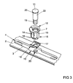
- Figure 3 shows an exploded view of the fitting part 1 of Figure 1. It can be seen that the foot part 11 has a cylindrical shaft 22 for guiding the head part 12. Furthermore, the foot part 11 at its end facing away from the drive rod 3 has a radial widening 23 for engaging behind the head part 12. The penetrating into the drive rod 3 rivet pin 19 of the foot part eleventh Like the recess 20 in the drive rod 3 is made out of round and thus allows a non-rotatable mounting of the foot part eleventh
- FIG. 4 shows a further embodiment of the fitting part 1 according to the invention in a longitudinal section.
- the shaft 22 of the foot part 11 is longer than a guide 24 of the head part 12.
- the head part 12 can be slightly displaced axially on the foot part 11 and compensate for tolerances in a folded air of the window.
- Figure 5 shows a sectional view through the fitting part 1 of Figure 4 along the line V - V.
- the spring element 18 is designed to be longer than the widening 10 of the slot 4 is wide. For a faulty twisted mounting of the spring element 18 is excluded. Furthermore, the ends of the widening 10 of the slot 4 and the spring element 18 have opposing ramps 25, 26 and thus allow easy removal of the spring element 18 from the widening 10 of the elongated hole 4 in a drive of the drive rod. 3
Landscapes
- Engineering & Computer Science (AREA)
- Mechanical Engineering (AREA)
- Structural Engineering (AREA)
- Lock And Its Accessories (AREA)
- Window Of Vehicle (AREA)
- Door And Window Frames Mounted To Openings (AREA)
- Orthopedics, Nursing, And Contraception (AREA)
- Stringed Musical Instruments (AREA)
- Materials For Medical Uses (AREA)
- Snaps, Bayonet Connections, Set Pins, And Snap Rings (AREA)
- Closing And Opening Devices For Wings, And Checks For Wings (AREA)
- Mutual Connection Of Rods And Tubes (AREA)
- Fishing Rods (AREA)
- Shafts, Cranks, Connecting Bars, And Related Bearings (AREA)
Abstract
Description
- Die Erfindung betrifft ein Beschlagteil für einen Treibstangenbeschlag eines Fensters, einer Fenstertür oder dergleichen mit einem auf einer längsbeweglich geführten Treibstange angeordneten Schließzapfen, mit einer die Treibstange abdeckenden Stulpschiene, mit einem in der Stulpschiene angeordneten Langloch zur Durchführung des Schließzapfens, mit einer an einer Stelle des Langlochs angeordneten Verbreiterung, mit einer exzentrisch zur Aufnahme des Schließzapfens in der Treibstange angeordneten Außenmantelfläche des Schließzapfens, mit einem in der Treibstange befestigten Fußteil des Schließzapfens und einem die Außenmantelfläche aufweisenden Kopfteil des Schließzapfens, wobei in einer Stellung das Kopfteil gegenüber dem Fußteil verdrehbar ist und ein Federelement zur Erzeugung einer kraftschlüssigen drehfesten Verbindung des Kopfteils gegenüber dem Fußteil ausgebildet ist.
- Ein solches Beschlagteil ist beispielsweise aus der
DE 101 58 359 A1 bekannt. Bei diesem Beschlagteil weisen das Fußteil und das Kopfteil miteinander korrespondierende Formschlussflächen auf. Das Federelement stützt sich an der Treibstange ab und spannt das Kopfteil gegen die Formschlussflächen des Fußteils. Die Formschlussflächen ermöglichen damit eine zuverlässige Festlegung der Stellung der Außenmantelfläche des Schließzapfens zu der Treibstange. Zur Verstellung wird das Kopfteil gegen die Kraft des Federelementes von den Formschlussflächen des Fußteils weg gedrückt und kann verdreht werden. Durch die Verstellung der exzentrischen Außenmantelfläche wird im montierten Zustand des Beschlagteils eine Einstellung der Vorspannkraft eines Flügels des Fensters gegen einen Rahmen ermöglicht. Die Formschlussflächen des Kopfteils und des Fußteils verhindern, dass sich die Außenmantelfläche verdreht, wenn der Schließzapfen an einer Kante eines Schließblechs des Treibstangenbeschlages entlang reibt. Nachteilig bei dem bekannten Beschlagteil ist, dass es aufwändig zu fertigen und zu montieren ist. - Der Erfindung liegt das Problem zugrunde, ein Beschlagteil der eingangs genannten Art so weiterzubilden, dass es besonders kostengünstig zu fertigen.
- Dieses Problem wird erfindungsgemäß dadurch gelöst, dass ein in das Langloch der Stulpschiene eindringender Abschnitt des Kopfteils mehrere, exzentrisch zu der Außenmantelfläche angeordnete, parallele Formschlussflächen hat, dass das Kopfteil drehbar auf dem Fußteil angeordnet ist und dass das Langloch eine die Verdrehung des Kopfteils verhindernde Breite und die Verbreiterung des Langlochs eine die Verdrehung des Kopfteils ermöglichende Breite hat.
- Durch diese Gestaltung wird eine Verdrehung des Kopfteils durch die in dem Langloch angeordneten Formschlussflächen des Kopfteils verhindert. Damit benötigt das Fußteil keine Formschlussflächen. Dies führt zu besonders geringen Fertigungskosten des erfindungsgemäßen Beschlagteils. Erst wenn das Kopfteil in die Verbreiterung des Langlochs bewegt wird, lässt sich die Außenmantelfläche des Schließzapfens gegenüber der Treibstange verstellen.
- Das Federelement gestaltet sich gemäß einer vorteilhaften Weiterbildung der Erfindung konstruktiv besonders einfach, wenn das Federelement U-förmig gebogen ist und gegen die Formschlussflächen vorgespannt ist. Durch diese Gestaltung wird das Federelement geringfügig aufgebogen, wenn bei dem in der Verbreiterung des Langlochs befindlichen Schließzapfen das Kopfteil verdreht wird.
- Eine besonders zuverlässige Unverdrehbarkeit der Führung des Schließzapfens in dem Langloch lässt sich einfach erreichen, wenn das Langloch die Breite zweier paralleler Formschlussflächen hat.
- Bei in dem Langloch außerhalb der Verbreiterung befindlichem Schließzapfen wird das Federelement zuverlässig gegen die Formschlussflächen des Kopfteils vorgespannt, wenn das Langloch die Breite zweier paralleler Formschlussflächen und des Federelementes hat.
- Das Kopfteil und das Fußteil könnten beispielsweise miteinander korrespondierende Rastmittel aufweisen, gegen die sie durch das Federelement vorgespannt sind. Rastmittel an dem Fußteil und dem Kopfteil lassen sich jedoch gemäß einer anderen vorteilhaften Weiterbildung der Erfindung einfach vermeiden, wenn das Federelement formschlüssig mit dem Fußteil verbunden ist. Diese Gestaltung führt zu einer weiteren Vereinfachung der Fertigung der Bauteile des erfindungsgemäßen Beschlagteils.
- Die Montage des erfindungsgemäßen Beschlagteils gestaltet sich besonders einfach und lässt sich einfach automatisieren, wenn das Kopfteil, das Fußteil und das Federelement als vormontierbare bauliche Einheit ausgebildet sind. Durch diese Gestaltung lassen sich sämtliche Bauteile des Schließzapfens zu der baulichen Einheit zusammenfassen und gemeinsam in eine weitere Einheit aus Treibstange und Stulpschiene einsetzen. Hierdurch wird vermieden, dass, wie bei dem bekannten Beschlagteil, mehrere Einzelteile an der Treibstange und der Stulpschiene angesetzt werden müssen.
- Ein fehlerhafter verdrehter Einsatz des Federelementes lässt sich gemäß einer anderen vorteilhaften Weiterbildung der Erfindung einfach vermeiden, wenn das Federelement länger ist als die Verbreiterung des Langlochs.
- Das Federelement weist gemäß einer anderen vorteilhaften Weiterbildung der Erfindung besonders kleine Abmessungen auf und lässt sich quer zur Bewegungsrichtung des Schließzapfens in dem Langloch montieren, wenn das Federelement kürzer ist, als das Langloch breit ist.
- Ein Ausgleich von Toleranzen in einer Falzluft des Fensters durch das erfindungsgemäße Beschlagteil lässt sich einfach erzeugen, wenn das Fußteil eine axiale Führung für das Kopfteil und eine das Kopfteil hintergreifende Verbreiterung aufweist.
- Zur weiteren Vereinfachung der Montage des erfindungsgemäßen Beschlagteils trägt es bei, wenn das Fußteil einen mit der Treibstange vernieteten Nietbolzen hat.
- Eine Einleitung eines Drehmoments in das Kopfteil beim Verschieben des Schließzapfens im Bereich des Langlochs außerhalb der Verbreiterung lässt sich gemäß einer anderen vorteilhaften Weiterbildung der Erfindung einfach vermeiden, wenn die Außenmantelfläche mehrere plane, in dem Langloch der Stulpschiene geführte Anlageflächen hat.
- Eine einfache Verdrehbarkeit des Kopfteils von Hand lässt sich gemäß einer anderen vorteilhaften Weiterbildung der Erfindung erzeugen, wenn eine am freien Ende des Kopfteils angeordnete radiale Verbreiterung unrund gestaltet ist. Durch die unrunde Gestaltung lässt sich das freie Ende des Kopfteils einfach greifen. Weiterhin ermöglicht die radiale Verbreiterung des Kopfteils ein Hintergreifen eines Randes des Schließblechs des Treibstangenbeschlages und damit eine hohe Sicherheit gegen einen Aufbruchsversuch des mit dem erfindungsgemäßen Beschlagteil ausgestatteten Fensters.
- Eine unbeabsichtigte Verstellung des Kopfteils lässt sich gemäß einer anderen vorteilhaften Weiterbildung der Erfindung einfach vermeiden, wenn die Verbreiterung des Langlochs der Stulpschiene in einer eine Öffnungsstellung des Treibstangenbeschlages kennzeichnenden Stellung angeordnet ist. Bei in Deutschland üblichen Treibstangenbeschlägen mit einer Zu- Dreh- Kipp- Schaltfolge ist dies die Mittelstellung, in der ein mit dem erfindungsgemäßen Beschlagteil ausgestattetes Fenster geöffnet werden kann. Diese Gestaltung stellt sicher, dass das Kopfteil und damit die Stellung der Außenmantelfläche ausschließlich in der Öffnungsstellung des Treibstangenbeschlages verstellt werden kann.
- Ein besonders reibungsarmes Einführen des Schließzapfens aus der Verbreiterung des Langlochs in die übrigen Bereiche des Langlochs lässt sich gemäß einer anderen vorteilhaften Weiterbildung der Erfindung einfach sicherstellen, wenn die Verbreiterung des Langlochs und/oder das Federelement an ihren einander zugewandten Enden zumindest eine Rampe aufweisen.
- Die Erfindung lässt zahlreiche Ausführungsformen zu. Zur weiteren Verdeutlichung ihres Grundprinzips sind zwei davon in der Zeichnung dargestellt und werden nachfolgend beschrieben. Diese zeigt in
- Fig. 1
- ein erfindungsgemäßes Beschlagteil mit angrenzenden Bereichen eines Treibstangenbeschlages,
- Fig. 2
- das erfindungsgemäße, aus zwei baulichen Einheiten bestehende Beschlagteil aus Figur 1 vor der Montage,
- Fig. 3
- eine Explosionsdarstellung des erfindungsgemäßen Beschlagteils aus Figur 1,
- Fig. 4
- einen Längsschnitt durch eine weitere Ausführungsform des erfindungsgemäßen Beschlagteils,
- Fig. 5
- eine Schnittdarstellung durch das Beschlagteil aus Figur 4 entlang der Linie V - V.
- Figur 1 zeigt ein Beschlagteil 1 für einen Treibstangenbeschlag eines Fensters, einer Fenstertür oder dergleichen mit einer unterhalb einer feststehenden Stulpschiene 2 längsverschieblich geführten Treibstange 3. Die Treibstange 3 weist ein Langloch 4 zur Durchführung eines Schließzapfens 5 auf. Der Schließzapfen 5 steht einem Schließblech 6 gegenüber. Im montierten Zustand ist der Schließzapfen 5 beispielsweise an einem Flügel und das Schließblech 6 an einem Rahmen des Fensters, der Fenstertür oder dergleichen befestigt. Eine an dem freien Ende des Schließzapfens 5 angeordnete, umlaufende, radiale Verbreiterung 7 dient zur Hintergreifung eines Randes 8 des Schließblechs 6. Der Schließzapfen 5 befindet sich in der Mittelstellung des Langlochs 4 und befindet sich in einer Ausnehmung 9 des Schließblechs 6. Dies kennzeichnet die Offenstellung des Treibstangenbeschlages, in der das Fenster geöffnet werden kann. Das Langloch 4 weist in dem mittleren Bereich, in dem sich der Schließzapfen 5 in der Offenstellung des Treibstangenbeschlages befindet, eine Verbreiterung 10 auf.
- Der Schließzapfen 5 weist ein mit der Treibstange 3 vernietetes Fußteil 11 und ein gegenüber diesem Fußteil 11 verdrehbares Kopfteil 12 auf. Das Kopfteil 12 hat eine exzentrisch zu dem Fußteil 11 angeordnete Außenmantelfläche 13 mit mehreren planen Anlageflächen 14 für das Schließblech 6. Weiterhin hat das Kopfteil 12 einen in das Langloch 4 eindringenden Abschnitt 15 mit mehreren, parallel zueinander angeordneten Formschlussflächen 16. Hierfür ist der Querschnitt dieses Abschnittes 15 beispielsweise achteckig geformt. Gegen die Formschlussflächen 16 sind Schenkel 17 eines U-förmigen Federelementes 18 vorgespannt. Das Federelement 18 ist auf dem Fußteil 11 befestigt. Hierdurch wird das Kopfteil 12 in seiner Lage gehalten. Das Kopfteil 12 lässt sich in der dargestellten Lage, in der sich der Schließzapfen 5 in der Verbreiterung 10 des Langlochs 4 befindet, gegenüber dem Fußteil 11 verdrehen. Dabei werden die Schenkel 17 des Federelementes 18 auseinandergedrückt. Damit lässt sich die Stellung der exzentrischen Außenmantelfläche 13 gegenüber dem Schließblech 6 verstellen und im montierten Zustand des Treibstangenbeschlages eine Vorspannung des Flügels gegen den Rahmen des Fensters einstellen. Das Langloch 4 weist außerhalb der Verbreiterung 10 eine den Abmessungen der Formschlussflächen 16 und des Federelementes 18 entsprechende Breite auf. Wenn man den Schließzapfen 5 durch Antrieb der Treibstange 3 aus der Verbreiterung 10 des Langlochs 4 heraus bewegt, lässt sich das Federelement 18 nicht mehr auseinander drücken. Das Kopfteil 12 ist daher außerhalb der Verbreiterung 10 des Langlochs 4 unverdrehbar gegenüber der Treibstange 3 gehalten. Beim Antrieb des Treibstangenbeschlages in eine Schließstellung gleiten die Anlageflächen 14 am Rand 8 des Schließblechs 6 entlang. Damit wird kein Drehmoment in das Kopfteil 12 eingeleitet. Die radiale Verbreiterung 7 des Kopfteils 12 des Schließzapfens 6 ist unrund gestaltet, um eine einfache Verdrehbarkeit des Kopfteils 12 von Hand zu gewährleisten.
- Figur 2 zeigt das Beschlagteil 1 aus Figur 1 vor der Montage. Hierbei ist zu erkennen, dass das Kopfteil 12, das Fußteil 11 und das Federelement 18 eine vormontierte bauliche Einheit des Schließzapfens 6 bilden. Die Treibstange 3 bildet mit der Stulpschiene 2 ebenfalls eine vormontierte bauliche Einheit. Zur Montage der beiden baulichen Einheiten wird ein Nietbolzen 19 des Fußteils 11 in eine Ausnehmung 20 der Treibstange 3 eingeführt und vernietet. Da das Federelement 18 an dem Fußteil 11 befestigt ist, wird die bauliche Einheit des Schließzapfens 6 zusammen gehalten.
- Figur 3 zeigt eine Explosionsdarstellung des Beschlagteils 1 aus Figur 1. Hierbei ist zu erkennen, dass das Fußteil 11 einen zylindrischen Schaft 22 zur Führung des Kopfteils 12 hat. Weiterhin hat das Fußteil 11 an seinem der Treibstange 3 abgewandten Ende eine radiale Verbreiterung 23 zur Hintergreifung des Kopfteils 12. Der in die Treibstange 3 eindringende Nietbolzen 19 des Fußteils 11 ist wie die Ausnehmung 20 in der Treibstange 3 unrund gefertigt und ermöglicht damit eine unverdrehbare Befestigung des Fußteils 11.
- Figur 4 zeigt eine weitere Ausführungsform des erfindungsgemäßen Beschlagteils 1 in einem Längsschnitt. Bei dieser Ausführungsform ist der Schaft 22 des Fußteils 11 länger als eine Führung 24 des Kopfteils 12. Damit lässt sich das Kopfteil 12 geringfügig auf dem Fußteil 11 axial verschieben und Toleranzen in einer Falzluft des Fensters ausgleichen.
- Figur 5 zeigt eine Schnittdarstellung durch das Beschlagteil 1 aus Figur 4 entlang der Linie V - V. Das Federelement 18 ist länger gestaltet als die Verbreiterung 10 des Langlochs 4 breit ist. Damit ist eine fehlerhafte verdrehte Montage des Federelementes 18 ausgeschlossen. Weiterhin haben die Enden der Verbreiterung 10 des Langlochs 4 und das Federelement 18 einander gegenüberstehende Rampen 25, 26 und ermöglichen damit ein einfaches Herausbewegen des Federelementes 18 aus der Verbreiterung 10 des Langlochs 4 bei einem Antrieb der Treibstange 3.
Claims (14)
- Beschlagteil für einen Treibstangenbeschlag eines Fensters, einer Fenstertür oder dergleichen mit einem auf einer längsbeweglich geführten Treibstange angeordneten Schließzapfen, mit einer die Treibstange abdeckenden Stulpschiene, mit einem in der Stulpschiene angeordneten Langloch zur Durchführung des Schließzapfens, mit einer an einer Stelle des Langlochs angeordneten Verbreiterung, mit einer exzentrisch zur Aufnahme des Schließzapfens in der Treibstange angeordneten Außenmantelfläche des Schließzapfens, mit einem in der Treibstange befestigten Fußteil des Schließzapfens und einem die Außenmantelfläche aufweisenden Kopfteil des Schließzapfens, wobei in einer Stellung das Kopfteil gegenüber dem Fußteil verdrehbar ist und ein Federelement zur Erzeugung einer kraftschlüssigen drehfesten Verbindung des Kopfteils gegenüber dem Fußteil ausgebildet ist, dadurch gekennzeichnet, dass ein in das Langloch (4) der Stulpschiene (2) eindringender Abschnitt (15) des Kopfteils (12) mehrere, exzentrisch zu der Außenmantelfläche (13) angeordnete, parallele Formschlussflächen (16) hat, dass das Kopfteil (12) drehbar auf dem Fußteil (11) angeordnet ist und dass das Langloch (4) eine die Verdrehung des Kopfteils (12) verhindernde Breite und die Verbreiterung (10) des Langlochs (4) eine die Verdrehung des Kopfteils (12) ermöglichende Breite hat.
- Beschlagteil nach Anspruch 1, dadurch gekennzeichnet, dass das Federelement (18) U-förmig gebogen ist und gegen die Formschlussflächen (16) vorgespannt ist.
- Beschlagteil nach Anspruch 1 oder 2, dadurch gekennzeichnet, dass das Langloch (4) die Breite zweier paralleler Formschlussflächen (16) hat.
- Beschlagteil nach Anspruch 2, dadurch gekennzeichnet, dass das Langloch (4) die Breite zweier paralleler Formschlussflächen (16) und des Federelementes (18) hat.
- Beschlagteil nach Anspruch 2, dadurch gekennzeichnet, dass das Federelement (18) formschlüssig mit dem Fußteil (11) verbunden ist.
- Beschlagteil nach Anspruch 2 oder 5, dadurch gekennzeichnet, dass das Kopfteil (12), das Fußteil (11) und das Federelement (18) als vormontierbare bauliche Einheit ausgebildet sind.
- Beschlagteil nach einem der vorhergehenden Ansprüche, dadurch gekennzeichnet, dass das Federelement (18) länger ist als die Verbreiterung (10) des Langlochs (4).
- Beschlagteil nach einem der vorhergehenden Ansprüche, dadurch gekennzeichnet, dass das Federelement (18) kürzer ist, als das Langloch (4) breit ist.
- Beschlagteil nach einem der vorhergehenden Ansprüche, dadurch gekennzeichnet, dass das Fußteil (11) eine axiale Führung (24) für das Kopfteil (12) und eine das Kopfteil (12) hintergreifende Verbreiterung (23) aufweist.
- Beschlagteil nach einem der vorhergehenden Ansprüche, dadurch gekennzeichnet, dass das Fußteil (11) einen mit der Treibstange (3) vernieteten Nietbolzen (19) hat.
- Beschlagteil nach einem der vorhergehenden Ansprüche, dadurch gekennzeichnet, dass die Außenmantelfläche (13) mehrere plane, in dem Langloch (4) der Stulpschiene (2) geführte Anlageflächen (14) hat.
- Beschlagteil nach einem der vorhergehenden Ansprüche, dadurch gekennzeichnet, dass eine am freien Ende des Kopfteils (12) angeordnete radiale Verbreiterung (7) unrund gestaltet ist.
- Beschlagteil nach einem der vorhergehenden Ansprüche, dadurch gekennzeichnet, dass die Verbreiterung (10) des Langlochs (4) der Stulpschiene (2) in einer eine Öffnungsstellung des Treibstangenbeschlages kennzeichnenden Stellung angeordnet ist.
- Beschlagteil nach einem der vorhergehenden Ansprüche, dadurch gekennzeichnet, dass die Verbreiterung (10) des Langlochs (4) und/oder das Federelement (18) an ihren einander zugewandten Enden zumindest eine Rampe (25, 26) aufweisen.
Priority Applications (1)
| Application Number | Priority Date | Filing Date | Title |
|---|---|---|---|
| PL06124038T PL1798360T3 (pl) | 2005-12-19 | 2006-11-14 | Element okuciowy dla okucia z prętem nastawczym |
Applications Claiming Priority (1)
| Application Number | Priority Date | Filing Date | Title |
|---|---|---|---|
| DE102005000189A DE102005000189A1 (de) | 2005-12-19 | 2005-12-19 | Beschlagteil für einen Treibstangenbeschlag |
Publications (3)
| Publication Number | Publication Date |
|---|---|
| EP1798360A2 true EP1798360A2 (de) | 2007-06-20 |
| EP1798360A3 EP1798360A3 (de) | 2008-06-18 |
| EP1798360B1 EP1798360B1 (de) | 2009-05-13 |
Family
ID=37944864
Family Applications (1)
| Application Number | Title | Priority Date | Filing Date |
|---|---|---|---|
| EP06124038A Not-in-force EP1798360B1 (de) | 2005-12-19 | 2006-11-14 | Beschlagteil für einen Treibstangenbeschlag |
Country Status (4)
| Country | Link |
|---|---|
| EP (1) | EP1798360B1 (de) |
| AT (1) | ATE431483T1 (de) |
| DE (2) | DE102005000189A1 (de) |
| PL (1) | PL1798360T3 (de) |
Cited By (2)
| Publication number | Priority date | Publication date | Assignee | Title |
|---|---|---|---|---|
| EP2295685A1 (de) * | 2009-08-26 | 2011-03-16 | Roto Frank Ag | Schließzapfen für einen Fenster- oder Türverriegelungsbeschlag |
| WO2019111171A1 (en) * | 2017-12-06 | 2019-06-13 | Capoferri Serramenti S.P.A. | Metalware for a window |
Families Citing this family (1)
| Publication number | Priority date | Publication date | Assignee | Title |
|---|---|---|---|---|
| DE102016225133A1 (de) * | 2016-12-15 | 2018-06-21 | Roto Frank Ag | Beschlag mit einer eine Durchgangsöffnung aufweisenden Stulpschiene |
Family Cites Families (7)
| Publication number | Priority date | Publication date | Assignee | Title |
|---|---|---|---|---|
| DE7313820U (de) * | 1973-04-12 | 1973-10-31 | Fa Aug Bilstein | Kantengetriebe mit getriebestange und darauf befestigtem verriegelungsbolzen |
| DE2705802C2 (de) * | 1977-02-11 | 1988-03-03 | Fa. Aug. Winkhaus, 4404 Telgte | Verriegelungsvorrichtung für Fenster, Türen oder dergleichen |
| DE2733710A1 (de) * | 1977-07-26 | 1979-02-01 | Winkhaus Fa August | Verriegelungsvorrichtung fuer fenster, tueren o.dgl. |
| DE19822864A1 (de) * | 1998-05-22 | 1999-11-25 | Winkhaus Fa August | Treibstange |
| DE19920832A1 (de) * | 1999-05-06 | 2000-11-09 | Winkhaus Fa August | Schließzapfen zur Verriegelung eines schwenkbaren Flügels |
| DE10140567B4 (de) * | 2001-08-18 | 2014-11-27 | Aug. Winkhaus Gmbh & Co. Kg | Beschlagteil für einen Treibstangenbeschlag |
| DE10158359A1 (de) * | 2001-11-28 | 2003-06-12 | Winkhaus Fa August | Beschlagteil für einen Treibstangenbeschlag |
-
2005
- 2005-12-19 DE DE102005000189A patent/DE102005000189A1/de not_active Withdrawn
-
2006
- 2006-11-14 PL PL06124038T patent/PL1798360T3/pl unknown
- 2006-11-14 DE DE502006003707T patent/DE502006003707D1/de active Active
- 2006-11-14 EP EP06124038A patent/EP1798360B1/de not_active Not-in-force
- 2006-11-14 AT AT06124038T patent/ATE431483T1/de active
Cited By (2)
| Publication number | Priority date | Publication date | Assignee | Title |
|---|---|---|---|---|
| EP2295685A1 (de) * | 2009-08-26 | 2011-03-16 | Roto Frank Ag | Schließzapfen für einen Fenster- oder Türverriegelungsbeschlag |
| WO2019111171A1 (en) * | 2017-12-06 | 2019-06-13 | Capoferri Serramenti S.P.A. | Metalware for a window |
Also Published As
| Publication number | Publication date |
|---|---|
| EP1798360B1 (de) | 2009-05-13 |
| DE502006003707D1 (de) | 2009-06-25 |
| PL1798360T3 (pl) | 2009-10-30 |
| EP1798360A3 (de) | 2008-06-18 |
| ATE431483T1 (de) | 2009-05-15 |
| DE102005000189A1 (de) | 2007-06-21 |
Similar Documents
| Publication | Publication Date | Title |
|---|---|---|
| DE2932784C2 (de) | Riegelverschluß an einem inneren Fensterflügel eines zweiflügeligen Schiebefensters od. dgl. | |
| EP2546438B1 (de) | Zur verschieblichen Montage in einer einen Hinterschnitt aufweisenden Beschlagnut vorgesehenes Beschlagteil | |
| DE102019125148A1 (de) | Nebenschloss für eine Mehrpunktverriegelung | |
| EP1798360B1 (de) | Beschlagteil für einen Treibstangenbeschlag | |
| EP1298269B1 (de) | Betätigungsgetriebe, insbesondere Schloss für einen Treibstangenbeschlag sowie Treibstangenbeschlag mit einem solchen Betätigungsgetriebe | |
| EP2251508A2 (de) | Schliessblech für Fenster oder Türen | |
| EP2754804B1 (de) | Verschluss für einen Treibstangenbeschlag | |
| EP1757761B1 (de) | Beschlagteil für einen Treibstangenbeschlag | |
| EP0808974A2 (de) | Schnappriegelvorrichtung für Flügel von Fenstern, Türen oder dgl. | |
| EP3626916B1 (de) | Treibstangenbeschlag | |
| DE102004060717B4 (de) | Verschluss zur Verriegelung eines Flügels in einem Rahmen eines Fensters | |
| EP0930410B1 (de) | Betätigungshandhabe | |
| EP2365164B1 (de) | Verschlussvorrichtung | |
| EP1757760B1 (de) | Beschlagteil für einen Treibstangenbeschlag | |
| EP1757759B1 (de) | Beschlagteil für einen Treibstangenbeschlag | |
| DE102004049068A1 (de) | Schnäpper für Balkon-oder Terrassentüren | |
| DE9314325U1 (de) | Flügelscharnier | |
| DE19916940B4 (de) | Schließzapfen | |
| EP3783176B1 (de) | Treibstangenbeschlag, tür- oder fensterverschluss und tür- oder fensteranordnung | |
| DE19909268B4 (de) | Verschluß zur Verriegelung eines schwenkbaren Flügels | |
| EP1867818B1 (de) | Verschluss für einen Treibstangenbeschlag und Fenster, Fenstertür oder dergleichen mit einem solchen Verschluss | |
| EP1936078A2 (de) | Beschlaggarnitur für einen Panikverschluss | |
| EP1726756B1 (de) | Beschlagteil für einen Treibstangenbeschlag | |
| WO2025087825A1 (de) | MITTELSTOßVERRIEGELUNG ZUR VERLAGERUNG EINES VERSCHIEBBAREN SCHIEBEFLÜGELS SENKRECHT ZU SEINER EBENE | |
| DE102006035416A1 (de) | Verschluss für einen Treibstangenbeschlag |
Legal Events
| Date | Code | Title | Description |
|---|---|---|---|
| PUAI | Public reference made under article 153(3) epc to a published international application that has entered the european phase |
Free format text: ORIGINAL CODE: 0009012 |
|
| AK | Designated contracting states |
Kind code of ref document: A2 Designated state(s): AT BE BG CH CY CZ DE DK EE ES FI FR GB GR HU IE IS IT LI LT LU LV MC NL PL PT RO SE SI SK TR |
|
| AX | Request for extension of the european patent |
Extension state: AL BA HR MK YU |
|
| PUAL | Search report despatched |
Free format text: ORIGINAL CODE: 0009013 |
|
| AK | Designated contracting states |
Kind code of ref document: A3 Designated state(s): AT BE BG CH CY CZ DE DK EE ES FI FR GB GR HU IE IS IT LI LT LU LV MC NL PL PT RO SE SI SK TR |
|
| AX | Request for extension of the european patent |
Extension state: AL BA HR MK RS |
|
| 17P | Request for examination filed |
Effective date: 20081031 |
|
| GRAP | Despatch of communication of intention to grant a patent |
Free format text: ORIGINAL CODE: EPIDOSNIGR1 |
|
| AKX | Designation fees paid |
Designated state(s): AT BE BG CH CY CZ DE DK EE ES FI FR GB GR HU IE IS IT LI LT LU LV MC NL PL PT RO SE SI SK TR |
|
| GRAS | Grant fee paid |
Free format text: ORIGINAL CODE: EPIDOSNIGR3 |
|
| GRAA | (expected) grant |
Free format text: ORIGINAL CODE: 0009210 |
|
| AK | Designated contracting states |
Kind code of ref document: B1 Designated state(s): AT BE BG CH CY CZ DE DK EE ES FI FR GB GR HU IE IS IT LI LT LU LV MC NL PL PT RO SE SI SK TR |
|
| REG | Reference to a national code |
Ref country code: GB Ref legal event code: FG4D Free format text: NOT ENGLISH |
|
| REG | Reference to a national code |
Ref country code: CH Ref legal event code: EP |
|
| REG | Reference to a national code |
Ref country code: IE Ref legal event code: FG4D |
|
| REF | Corresponds to: |
Ref document number: 502006003707 Country of ref document: DE Date of ref document: 20090625 Kind code of ref document: P |
|
| REG | Reference to a national code |
Ref country code: DE Ref legal event code: R096 Ref document number: 502006003707 Country of ref document: DE Effective date: 20090625 |
|
| PG25 | Lapsed in a contracting state [announced via postgrant information from national office to epo] |
Ref country code: PT Free format text: LAPSE BECAUSE OF FAILURE TO SUBMIT A TRANSLATION OF THE DESCRIPTION OR TO PAY THE FEE WITHIN THE PRESCRIBED TIME-LIMIT Effective date: 20090913 Ref country code: FI Free format text: LAPSE BECAUSE OF FAILURE TO SUBMIT A TRANSLATION OF THE DESCRIPTION OR TO PAY THE FEE WITHIN THE PRESCRIBED TIME-LIMIT Effective date: 20090513 Ref country code: LT Free format text: LAPSE BECAUSE OF FAILURE TO SUBMIT A TRANSLATION OF THE DESCRIPTION OR TO PAY THE FEE WITHIN THE PRESCRIBED TIME-LIMIT Effective date: 20090513 Ref country code: ES Free format text: LAPSE BECAUSE OF FAILURE TO SUBMIT A TRANSLATION OF THE DESCRIPTION OR TO PAY THE FEE WITHIN THE PRESCRIBED TIME-LIMIT Effective date: 20090824 |
|
| REG | Reference to a national code |
Ref country code: PL Ref legal event code: T3 |
|
| NLV1 | Nl: lapsed or annulled due to failure to fulfill the requirements of art. 29p and 29m of the patents act | ||
| PG25 | Lapsed in a contracting state [announced via postgrant information from national office to epo] |
Ref country code: SE Free format text: LAPSE BECAUSE OF FAILURE TO SUBMIT A TRANSLATION OF THE DESCRIPTION OR TO PAY THE FEE WITHIN THE PRESCRIBED TIME-LIMIT Effective date: 20090813 Ref country code: NL Free format text: LAPSE BECAUSE OF FAILURE TO SUBMIT A TRANSLATION OF THE DESCRIPTION OR TO PAY THE FEE WITHIN THE PRESCRIBED TIME-LIMIT Effective date: 20090513 Ref country code: SI Free format text: LAPSE BECAUSE OF FAILURE TO SUBMIT A TRANSLATION OF THE DESCRIPTION OR TO PAY THE FEE WITHIN THE PRESCRIBED TIME-LIMIT Effective date: 20090513 Ref country code: LV Free format text: LAPSE BECAUSE OF FAILURE TO SUBMIT A TRANSLATION OF THE DESCRIPTION OR TO PAY THE FEE WITHIN THE PRESCRIBED TIME-LIMIT Effective date: 20090513 Ref country code: IS Free format text: LAPSE BECAUSE OF FAILURE TO SUBMIT A TRANSLATION OF THE DESCRIPTION OR TO PAY THE FEE WITHIN THE PRESCRIBED TIME-LIMIT Effective date: 20090913 |
|
| REG | Reference to a national code |
Ref country code: IE Ref legal event code: FD4D |
|
| PG25 | Lapsed in a contracting state [announced via postgrant information from national office to epo] |
Ref country code: IE Free format text: LAPSE BECAUSE OF FAILURE TO SUBMIT A TRANSLATION OF THE DESCRIPTION OR TO PAY THE FEE WITHIN THE PRESCRIBED TIME-LIMIT Effective date: 20090513 Ref country code: CZ Free format text: LAPSE BECAUSE OF FAILURE TO SUBMIT A TRANSLATION OF THE DESCRIPTION OR TO PAY THE FEE WITHIN THE PRESCRIBED TIME-LIMIT Effective date: 20090513 Ref country code: DK Free format text: LAPSE BECAUSE OF FAILURE TO SUBMIT A TRANSLATION OF THE DESCRIPTION OR TO PAY THE FEE WITHIN THE PRESCRIBED TIME-LIMIT Effective date: 20090513 Ref country code: EE Free format text: LAPSE BECAUSE OF FAILURE TO SUBMIT A TRANSLATION OF THE DESCRIPTION OR TO PAY THE FEE WITHIN THE PRESCRIBED TIME-LIMIT Effective date: 20090513 |
|
| PG25 | Lapsed in a contracting state [announced via postgrant information from national office to epo] |
Ref country code: SK Free format text: LAPSE BECAUSE OF FAILURE TO SUBMIT A TRANSLATION OF THE DESCRIPTION OR TO PAY THE FEE WITHIN THE PRESCRIBED TIME-LIMIT Effective date: 20090513 |
|
| PLBE | No opposition filed within time limit |
Free format text: ORIGINAL CODE: 0009261 |
|
| STAA | Information on the status of an ep patent application or granted ep patent |
Free format text: STATUS: NO OPPOSITION FILED WITHIN TIME LIMIT |
|
| PG25 | Lapsed in a contracting state [announced via postgrant information from national office to epo] |
Ref country code: BG Free format text: LAPSE BECAUSE OF FAILURE TO SUBMIT A TRANSLATION OF THE DESCRIPTION OR TO PAY THE FEE WITHIN THE PRESCRIBED TIME-LIMIT Effective date: 20090813 |
|
| 26N | No opposition filed |
Effective date: 20100216 |
|
| BERE | Be: lapsed |
Owner name: AUG. WINKHAUS G.M.B.H. & CO. KG Effective date: 20091130 |
|
| REG | Reference to a national code |
Ref country code: DE Ref legal event code: R097 Ref document number: 502006003707 Country of ref document: DE Effective date: 20100216 |
|
| PG25 | Lapsed in a contracting state [announced via postgrant information from national office to epo] |
Ref country code: MC Free format text: LAPSE BECAUSE OF NON-PAYMENT OF DUE FEES Effective date: 20091130 |
|
| PG25 | Lapsed in a contracting state [announced via postgrant information from national office to epo] |
Ref country code: BE Free format text: LAPSE BECAUSE OF NON-PAYMENT OF DUE FEES Effective date: 20091130 Ref country code: GR Free format text: LAPSE BECAUSE OF FAILURE TO SUBMIT A TRANSLATION OF THE DESCRIPTION OR TO PAY THE FEE WITHIN THE PRESCRIBED TIME-LIMIT Effective date: 20090814 |
|
| PG25 | Lapsed in a contracting state [announced via postgrant information from national office to epo] |
Ref country code: RO Free format text: LAPSE BECAUSE OF FAILURE TO SUBMIT A TRANSLATION OF THE DESCRIPTION OR TO PAY THE FEE WITHIN THE PRESCRIBED TIME-LIMIT Effective date: 20090513 |
|
| PG25 | Lapsed in a contracting state [announced via postgrant information from national office to epo] |
Ref country code: IT Free format text: LAPSE BECAUSE OF FAILURE TO SUBMIT A TRANSLATION OF THE DESCRIPTION OR TO PAY THE FEE WITHIN THE PRESCRIBED TIME-LIMIT Effective date: 20090513 |
|
| PG25 | Lapsed in a contracting state [announced via postgrant information from national office to epo] |
Ref country code: LU Free format text: LAPSE BECAUSE OF NON-PAYMENT OF DUE FEES Effective date: 20091114 |
|
| PG25 | Lapsed in a contracting state [announced via postgrant information from national office to epo] |
Ref country code: HU Free format text: LAPSE BECAUSE OF FAILURE TO SUBMIT A TRANSLATION OF THE DESCRIPTION OR TO PAY THE FEE WITHIN THE PRESCRIBED TIME-LIMIT Effective date: 20091114 |
|
| REG | Reference to a national code |
Ref country code: CH Ref legal event code: PL |
|
| PG25 | Lapsed in a contracting state [announced via postgrant information from national office to epo] |
Ref country code: LI Free format text: LAPSE BECAUSE OF NON-PAYMENT OF DUE FEES Effective date: 20101130 Ref country code: CH Free format text: LAPSE BECAUSE OF NON-PAYMENT OF DUE FEES Effective date: 20101130 |
|
| PG25 | Lapsed in a contracting state [announced via postgrant information from national office to epo] |
Ref country code: TR Free format text: LAPSE BECAUSE OF FAILURE TO SUBMIT A TRANSLATION OF THE DESCRIPTION OR TO PAY THE FEE WITHIN THE PRESCRIBED TIME-LIMIT Effective date: 20090513 |
|
| PG25 | Lapsed in a contracting state [announced via postgrant information from national office to epo] |
Ref country code: CY Free format text: LAPSE BECAUSE OF FAILURE TO SUBMIT A TRANSLATION OF THE DESCRIPTION OR TO PAY THE FEE WITHIN THE PRESCRIBED TIME-LIMIT Effective date: 20090513 |
|
| REG | Reference to a national code |
Ref country code: FR Ref legal event code: PLFP Year of fee payment: 10 |
|
| PGFP | Annual fee paid to national office [announced via postgrant information from national office to epo] |
Ref country code: GB Payment date: 20151130 Year of fee payment: 10 |
|
| PGFP | Annual fee paid to national office [announced via postgrant information from national office to epo] |
Ref country code: PL Payment date: 20151103 Year of fee payment: 10 |
|
| REG | Reference to a national code |
Ref country code: FR Ref legal event code: PLFP Year of fee payment: 11 |
|
| PGFP | Annual fee paid to national office [announced via postgrant information from national office to epo] |
Ref country code: FR Payment date: 20161129 Year of fee payment: 11 |
|
| GBPC | Gb: european patent ceased through non-payment of renewal fee |
Effective date: 20161114 |
|
| PG25 | Lapsed in a contracting state [announced via postgrant information from national office to epo] |
Ref country code: GB Free format text: LAPSE BECAUSE OF NON-PAYMENT OF DUE FEES Effective date: 20161114 |
|
| PGFP | Annual fee paid to national office [announced via postgrant information from national office to epo] |
Ref country code: AT Payment date: 20171128 Year of fee payment: 12 |
|
| PG25 | Lapsed in a contracting state [announced via postgrant information from national office to epo] |
Ref country code: PL Free format text: LAPSE BECAUSE OF NON-PAYMENT OF DUE FEES Effective date: 20161114 |
|
| REG | Reference to a national code |
Ref country code: FR Ref legal event code: ST Effective date: 20180731 |
|
| PG25 | Lapsed in a contracting state [announced via postgrant information from national office to epo] |
Ref country code: FR Free format text: LAPSE BECAUSE OF NON-PAYMENT OF DUE FEES Effective date: 20171130 |
|
| REG | Reference to a national code |
Ref country code: AT Ref legal event code: MM01 Ref document number: 431483 Country of ref document: AT Kind code of ref document: T Effective date: 20181114 |
|
| PG25 | Lapsed in a contracting state [announced via postgrant information from national office to epo] |
Ref country code: AT Free format text: LAPSE BECAUSE OF NON-PAYMENT OF DUE FEES Effective date: 20181114 |
|
| P01 | Opt-out of the competence of the unified patent court (upc) registered |
Effective date: 20230515 |
|
| PGFP | Annual fee paid to national office [announced via postgrant information from national office to epo] |
Ref country code: DE Payment date: 20231120 Year of fee payment: 18 |
|
| REG | Reference to a national code |
Ref country code: DE Ref legal event code: R119 Ref document number: 502006003707 Country of ref document: DE |
|
| PG25 | Lapsed in a contracting state [announced via postgrant information from national office to epo] |
Ref country code: DE Free format text: LAPSE BECAUSE OF NON-PAYMENT OF DUE FEES Effective date: 20250603 |