EP1797232B1 - Reibungsdämpfereinrichtung für eine waschmachine - Google Patents
Reibungsdämpfereinrichtung für eine waschmachine Download PDFInfo
- Publication number
- EP1797232B1 EP1797232B1 EP05801278.2A EP05801278A EP1797232B1 EP 1797232 B1 EP1797232 B1 EP 1797232B1 EP 05801278 A EP05801278 A EP 05801278A EP 1797232 B1 EP1797232 B1 EP 1797232B1
- Authority
- EP
- European Patent Office
- Prior art keywords
- piston rod
- friction
- damper device
- friction lining
- friction damper
- Prior art date
- Legal status (The legal status is an assumption and is not a legal conclusion. Google has not performed a legal analysis and makes no representation as to the accuracy of the status listed.)
- Expired - Lifetime
Links
Images


Classifications
-
- F—MECHANICAL ENGINEERING; LIGHTING; HEATING; WEAPONS; BLASTING
- F16—ENGINEERING ELEMENTS AND UNITS; GENERAL MEASURES FOR PRODUCING AND MAINTAINING EFFECTIVE FUNCTIONING OF MACHINES OR INSTALLATIONS; THERMAL INSULATION IN GENERAL
- F16F—SPRINGS; SHOCK-ABSORBERS; MEANS FOR DAMPING VIBRATION
- F16F7/00—Vibration-dampers; Shock-absorbers
- F16F7/08—Vibration-dampers; Shock-absorbers with friction surfaces rectilinearly movable along each other
- F16F7/09—Vibration-dampers; Shock-absorbers with friction surfaces rectilinearly movable along each other in dampers of the cylinder-and-piston type
-
- D—TEXTILES; PAPER
- D06—TREATMENT OF TEXTILES OR THE LIKE; LAUNDERING; FLEXIBLE MATERIALS NOT OTHERWISE PROVIDED FOR
- D06F—LAUNDERING, DRYING, IRONING, PRESSING OR FOLDING TEXTILE ARTICLES
- D06F37/00—Details specific to washing machines covered by groups D06F21/00 - D06F25/00
- D06F37/20—Mountings, e.g. resilient mountings, for the rotary receptacle, motor, tub or casing; Preventing or damping vibrations
Definitions
- the present invention relates to a Reibungsdämpfer adopted for a washing machine, in whose housing a washing unit with a tub, a washing drum rotatably mounted in the washing tub and a drive for the laundry drum is arranged, wherein the washing unit by at least one, a piston rod having damper resiliently against a lower Supported frame part of the housing.
- washing machines In the context of washing machines are various systems for the storage of the washing unit, which consists of a tub, a drive for the tub and a laundry drum known.
- the washing unit In so-called elevated systems, the washing unit is usually mounted resiliently over several struts with respect to a lower frame part of the housing of the washing machine.
- suspended systems which are mixing systems, the washing unit is suspended at several points with the aid of springs on an upper frame part of the housing and damped with the aid of dampers with respect to a lower frame part of the housing with respect to the vibrations.
- a motorized friction breaker engages, which can push apart the friction heads against the biasing force of the tensioning and retaining brackets.
- the friction breaker is designed as a piston / cylinder drive which can be acted upon by a pressure fluid.
- the friction interrupter may comprise an electric motor and an adjusting spindle.
- the object of the present invention is to provide a relatively simple construction and a safe operation of the washing machine ensuring friction damper device.
- the main advantage is that the present friction damper device is relatively simple in construction and therefore inexpensive to produce.
- Another advantage of the invention is that in a sudden power failure, for example, in an accidental shutdown of the washing machine during its operation, the friction damper invention immediately and automatically unfolds its damper force and thus a safe "run through” the lower speed range is guaranteed to a standstill ,
- the present friction damping device is in particular in a speed range of the laundry drum from about 0 to 300 U / min, in which also the resonance range for the spin start, effectively switchable. Above this range, ie in the spin cycle, the damper forces do not disturb the vibration behavior of the washing unit, which is why the present Reibungsdämpfer Hughes is electrically either completely off or so switchable that their damping force is reduced.
- the vibration behavior of the entire washing machine is significantly improved. In particular, the vibration behavior of the overall device is improved and noise is reduced.
- the present friction damper device is then, when the upper rotational speed range of the spin cycle is exited, switched so that their damping effect occurs again.
- the present Reibungsdämpfer is used in elevated and suspended systems, as well as in mixing systems.
- the washing unit 2 of a known washing machine arranged in a housing 1 essentially comprises a tub 3, a washing drum 4 and a drive 5 arranged on the tub 3, which rotates the washing drum 3 about a horizontal axis 6.
- the washing unit 2 can with the Help of schematically illustrated tension springs 7 preferably be suspended directly on an upper frame of the housing 1.
- 3 dampers 8 may be provided on the tub, which are supported on the one hand on the washing unit 2 and on the other hand on a lower frame part 9 of the housing 1.
- the piston rods of the damper 8 are designated 10.
- the present invention provides a friction damper device 29 whose damper force can be electrically switched or controlled. Since above the aforementioned speed range, the damper forces would disturb the vibration behavior of the washing unit 2, the damper force of the present Reibungsdämpfer adopted 29 can be switched or reduced above this range completely ineffective, so that the vibration and vibration behavior of the entire washing machine much better and the noise generated become smaller in this upper speed range.
- the damper force of the present Reibungsdämpfer issued 29 can be switched on again.
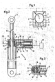
- FIG. 2 shows a preferred embodiment of the present Reibungsdämpfer worn 29.
- This essentially comprises in a conventional manner, a piston rod 10 of a damper 8, with its upper end 11 on the washing unit 2 and with its lower end 12 on a lower frame part 9 of the housing 1 of the washing machine is articulated.
- a piston rod 10 at least partially surrounding the cylindrical housing part 13 is a suitably transversely to the piston rod 10 extending plunger 15, preferably on its side facing the piston rod 10 a preferably plate-like trained attachment portion 18 on which a friction lining 16 is attached.
- an energy storage which preferably has the shape of a surrounding the plunger 15 helical compression spring 14, which is supported on the one hand on the neck portion 18 and the other part of the stop member 19 so that they the neck portion 18 with the friction lining 16 presses against the piston rod 10.
- the friction lining 16 is preferably annular, such that it is suitably applied with its friction surface 24 partially on the peripheral surface of the circular cylindrical piston rod 10 over the entire surface when the compression spring 15 unfolds its effect.
- the friction lining 16 is preferably fixed in a circular recess 26 of the attachment part 18, suitably glued.
- the friction lining 16 is designed so that it can engage approximately at half the peripheral surface of the piston rod 10.
- friction lining 16 of the piston rod 10 On the opposite side of the friction lining 16 of the piston rod 10 is another friction lining 17, which is preferably also annular, such that it with its friction surface 27 partially on the peripheral surface of the piston rod 10 is suitably applied over the entire surface, with its piston rod 10 side facing away preferably attached to a likewise circular inner wall 25 of the housing part 13, in particular glued.
- the plunger 15 is actuated by an electromagnetic actuator 20 against the force of the compression spring 15 such that the attachment part 18 is moved away with the friction lining 16 in an excitation of the actuator 20 of the piston rod 10, so that the piston rod 10 can swing freely.
- the electromagnetic actuator 20 is located in a housing part 22, which preferably has an end face forming the abutment part 19, which has an opening 21 through which the plunger 15 passes, wherein the housing part 22 is fastened to the housing part 13.
- the power supply of the actuator 20 serving electrical line is shown schematically and designated 23.
- the friction damper device 29 thus far described functions in the following manner.
- the actuator 20 is de-energized, so that the compression spring 15 unfolds its full effect and the friction lining 16 presses against the piston rod 10, so that it is held frictionally and dampening between the friction linings 16 and 17 and a vibration of the washing unit 2 is deployed damping effect.
- the electromagnetic actuator 20 is energized, so that the friction lining 16 is pulled away by a movement of the plunger 15 against the force of the compression spring 14 of the piston rod 10. An attenuation of the piston rod 10 is then not. Once the electromagnetic actuator 20 is de-energized, the plunger 15 is released and the compression spring 15 presses the friction lining 16 again against the piston rod 10th
- Fig. 4 and 5 a further embodiment of the present Reibungsdämpfer observed explained, in which the friction lining 31 is arranged on the circumference of a arranged in a cylinder 38 of the damper 8 and connected to the piston rod 10 piston 37 and biased by an energy storage against the inner wall of the cylinder 38.
- An actuator may have a friction lining 31 at its Move activation against the bias of the energy store away from the inner wall of the cylinder 38.
- the actuator is preferably arranged on the piston 37 memory metal part 32 which generates a force at its excitation, which moves the biased by the energy storage against the inner wall of the cylinder 38 friction lining 31 away from the inner wall or pulls away.
- the damping effect of the damper 8 is canceled.
- the friction lining 31 is expediently fastened on a carrier part 36, in particular adhesively bonded.
- the excitation of the memory metal part can be done in different ways.
- the introduction of thermal energy can be provided for this purpose.
- the piston 37 a further friction lining 35 mounted on a further support member 39, preferably glued, which is connected about a pivot point 40 rotatably connected to the support member 36.
- the support part 36 and the further support part 39 extend at least partially around the circumference of the piston 37 and engage on their side facing the piston 37 in each case into a circumferential groove 41 (FIG. Fig. 4 ) of the same one.
- the memory metal part 32 is rod-shaped and extends through a through the piston 37 leading through opening 42. It is attached at its one end to the support member 36 and at its other end to the further support member 39. The attachment preferably takes place via holding parts 43, which enable a particularly favorable and large-scale introduction of force into the respective carrier part 36 or 39.
- the pivot points 40 facing away from the end portions of the support member 36 and the other support member 39 are connected to each other by a return spring forming the energy storage 34.
- the return spring 34 presses the said end regions apart from the inner wall of the cylinder 38 in such a way that the friction lining 31 and the further friction lining 35 bear against the inner wall of the cylinder 38.
- the rod-shaped memory metal part 32 is formed by a metal wire.
- Fig. 6 shows a further embodiment of this friction damper device. Details of Fig. 6 already related to Fig. 4 and 5 are explained in the appropriate way.
- the actuator in this case is a memory wire 33, which is formed into a loop and when it is energized reduces the circumference of the loop.
- the loop extends around a arranged in a cavity 41 of the piston 37 and fixed to the support member 36 roller 40.
- the loop is attached to the roller 44 opposite side of the other support member 39 and the fulcrum 40 opposite end portions of the support member 36 and Further support member 39 are spread apart by the return spring 34.
Landscapes
- Engineering & Computer Science (AREA)
- General Engineering & Computer Science (AREA)
- Textile Engineering (AREA)
- Mechanical Engineering (AREA)
- Main Body Construction Of Washing Machines And Laundry Dryers (AREA)
- Vibration Prevention Devices (AREA)
Priority Applications (1)
| Application Number | Priority Date | Filing Date | Title |
|---|---|---|---|
| PL05801278T PL1797232T3 (pl) | 2004-10-01 | 2005-09-30 | Zespół tłumika ciernego dla pralki |
Applications Claiming Priority (2)
| Application Number | Priority Date | Filing Date | Title |
|---|---|---|---|
| DE102004047999A DE102004047999A1 (de) | 2004-10-01 | 2004-10-01 | Reibungsdämpfereinrichtung für eine Waschmaschine |
| PCT/EP2005/054958 WO2006037767A1 (de) | 2004-10-01 | 2005-09-30 | Reibungsdämpfereinrichtung für eine waschmaschine |
Publications (2)
| Publication Number | Publication Date |
|---|---|
| EP1797232A1 EP1797232A1 (de) | 2007-06-20 |
| EP1797232B1 true EP1797232B1 (de) | 2013-09-11 |
Family
ID=35519661
Family Applications (1)
| Application Number | Title | Priority Date | Filing Date |
|---|---|---|---|
| EP05801278.2A Expired - Lifetime EP1797232B1 (de) | 2004-10-01 | 2005-09-30 | Reibungsdämpfereinrichtung für eine waschmachine |
Country Status (5)
| Country | Link |
|---|---|
| US (2) | US20080256986A1 (pl) |
| EP (1) | EP1797232B1 (pl) |
| DE (1) | DE102004047999A1 (pl) |
| PL (1) | PL1797232T3 (pl) |
| WO (1) | WO2006037767A1 (pl) |
Families Citing this family (40)
| Publication number | Priority date | Publication date | Assignee | Title |
|---|---|---|---|---|
| DE102007028739B4 (de) * | 2007-06-21 | 2012-02-23 | Seuffer Gmbh & Co.Kg | Waschmaschine |
| ITMI20080237A1 (it) * | 2008-02-15 | 2009-08-16 | Cima Compagnia Italiana Molle A Acciaio Spa | Ammortizzatore a frizione per lavabiancheria |
| DE102008038133B4 (de) | 2008-08-18 | 2012-03-15 | Miele & Cie. Kg | Dämpfer für eine Waschmaschine |
| DE102008039569B4 (de) | 2008-08-25 | 2013-05-16 | Seuffer Gmbh & Co.Kg | Aufhängevorrichtung, Wascheinrichtung und Verfahren zur Steuerung einer Wascheinrichtung |
| FR2944078B1 (fr) * | 2009-04-06 | 2016-04-15 | Messier Dowty Sa | Dispositif lineaire a friction controlee avec pressage normal au deplacement |
| ES2607937T3 (es) * | 2010-05-11 | 2017-04-04 | Aksistem Elektromekanik Sanayi Ve Ticaret Ltd. | Amortiguador de fricción electromecánico |
| DE102010051663A1 (de) * | 2010-11-17 | 2012-05-24 | Liebherr-Hydraulikbagger Gmbh | Arbeitsgerät |
| DE102010063013A1 (de) | 2010-12-14 | 2012-06-14 | BSH Bosch und Siemens Hausgeräte GmbH | Waschmaschine, Waschtrockner od. dgl. mit hinzukommenden Antrieb bzw. Antriebssystem sowie Verfahren zum Betreiben eines solchen Antriebssystems |
| KR101286703B1 (ko) | 2011-10-07 | 2013-07-16 | 인하대학교 산학협력단 | 형상 기억 합금을 이용한 가변 마찰 댐퍼 |
| KR101286701B1 (ko) * | 2011-10-07 | 2013-07-16 | 인하대학교 산학협력단 | 가변 마찰 댐퍼 |
| ITPN20120003A1 (it) * | 2012-01-23 | 2013-07-24 | Ro Sa Plast Spa | Ammortizzatore con mezzi di regolazione della frenatura |
| ES2435102B1 (es) | 2012-05-23 | 2014-09-24 | Bsh Electrodomésticos España, S.A. | Dispositivo amortiguador rotatorio para aparato electrodoméstico |
| US10011936B2 (en) | 2012-07-30 | 2018-07-03 | Lg Electronics Inc. | Laundry processing machine |
| KR101916438B1 (ko) * | 2012-07-30 | 2018-11-07 | 엘지전자 주식회사 | 세탁물 처리기기 |
| EP2757282B1 (en) | 2013-01-21 | 2018-03-14 | Aksistem Elektromekanik Sanayi ve Ticaret Ltd. Sti. | Electromechanical shock absorber for washing machines |
| KR101449472B1 (ko) * | 2013-01-30 | 2014-10-13 | 인하대학교 산학협력단 | 급수압을 이용한 가변 마찰 댐퍼 |
| KR102315657B1 (ko) * | 2015-03-16 | 2021-10-20 | 엘지전자 주식회사 | 세탁물 처리기기 |
| KR102331601B1 (ko) * | 2015-04-01 | 2021-11-30 | 엘지전자 주식회사 | 지지장치 및 상기 지지장치가 구비된 의류처리장치 |
| ES2592569B1 (es) * | 2015-05-29 | 2017-09-08 | Bsh Electrodomésticos España, S.A. | Dispositivo amortiguador |
| US10253695B2 (en) * | 2015-08-14 | 2019-04-09 | United Technologies Corporation | Heat exchanger for cooled cooling air with adjustable damper |
| US10287982B2 (en) | 2015-08-14 | 2019-05-14 | United Technologies Corporation | Folded heat exchanger for cooled cooling air |
| DE102017217416A1 (de) * | 2017-09-29 | 2019-04-04 | E.G.O. Elektro-Gerätebau GmbH | Federeinrichtung zur federnden Lagerung einer Funktionseinheit eines Elektrogeräts und Verfahren zur Beeinflussung einer solchen Federeinrichtung |
| DE102018211770A1 (de) | 2018-07-16 | 2020-01-16 | BSH Hausgeräte GmbH | Schwingungsdämpfungssystem und Gerät zum Behandeln von Wäsche |
| DE102018211774A1 (de) | 2018-07-16 | 2020-01-16 | BSH Hausgeräte GmbH | Schwingungsdämpfungssystem und Gerät zum Behandeln von Wäsche |
| DE102018211769A1 (de) | 2018-07-16 | 2020-01-16 | BSH Hausgeräte GmbH | Schwingungsdämpfungssystem und Gerät zum Behandeln von Wäsche |
| DE102018211772A1 (de) | 2018-07-16 | 2020-01-16 | BSH Hausgeräte GmbH | Schwingungsdämpfungssystem und Gerät zum Behandeln von Wäsche |
| CN111485375B (zh) * | 2019-01-29 | 2023-04-21 | 青岛海尔洗衣机有限公司 | 一种阻尼减震器及装有该减震器的洗衣机及控制方法 |
| JP2020197277A (ja) * | 2019-06-05 | 2020-12-10 | 三星電子株式会社Samsung Electronics Co.,Ltd. | 減衰装置、洗濯機 |
| WO2020246754A1 (en) | 2019-06-05 | 2020-12-10 | Samsung Electronics Co., Ltd. | Damper and washing machine having the same |
| WO2021078394A1 (en) * | 2019-10-25 | 2021-04-29 | Electrolux Professional S.P.A. | Washing machine and a piston damper therefore |
| DE102020202348A1 (de) * | 2020-02-24 | 2021-08-26 | Suspa Gmbh | Reibungsdämpfer |
| DE102020111770A1 (de) | 2020-04-30 | 2021-11-04 | Miele & Cie. Kg | Dämpfer für eine Waschmaschine |
| DE102020206722A1 (de) * | 2020-05-28 | 2021-12-02 | Suspa Gmbh | Dämpferanordnung und Maschine für eine derartige Dämpferanordnung |
| EP4030077A1 (en) * | 2021-01-15 | 2022-07-20 | Öhlins Racing AB | Damper assembly and hydraulic shock absorber comprising the same |
| EP4438790A4 (en) * | 2022-06-21 | 2025-06-04 | Samsung Electronics Co., Ltd. | WASHING MACHINE HAVING A SHOCK ABSORBER TO ATTENTION VIBRATIONS OF A TUB |
| WO2023249245A1 (ko) * | 2022-06-21 | 2023-12-28 | 삼성전자 주식회사 | 터브의 진동을 감쇠하는 댐퍼를 갖는 세탁기 |
| DE102022209864A1 (de) * | 2022-09-20 | 2024-03-21 | Suspa Gmbh | Reibungsdämpfer |
| KR20240062842A (ko) * | 2022-11-02 | 2024-05-09 | 삼성전자주식회사 | 댐퍼 및 이를 포함하는 세탁기 |
| WO2025019879A1 (de) * | 2023-07-21 | 2025-01-30 | STIWA Advanced Products GmbH | Reibungsdämpfer, sowie ein mit dem reibungsdämpfer ausgestattetes wäschegerät |
| EP4549774A1 (en) * | 2023-10-31 | 2025-05-07 | Aksistem Elektromekanik Sanayi ve Ticaret Ltd. Sti. | A frictional damper with linear actuator |
Family Cites Families (12)
| Publication number | Priority date | Publication date | Assignee | Title |
|---|---|---|---|---|
| US4214795A (en) * | 1977-11-25 | 1980-07-29 | Shoketsu Kinzoku Kogyo Kabushiki Kaisha | Piston braking device for hydraulic or pneumatic cylinders |
| DE3016915A1 (de) * | 1980-05-02 | 1981-11-05 | Fritz Bauer + Söhne oHG, 8503 Altdorf | Schwingungsfaehige abstuetzung fuer waschmaschinen |
| DE3626065C2 (de) * | 1986-08-01 | 1995-04-27 | Suspa Compart Ag | Reibungs-Dämpfer für Waschmaschinen |
| DE3836367C1 (pl) * | 1988-10-26 | 1989-12-14 | J.M. Voith Gmbh, 7920 Heidenheim, De | |
| JPH04371194A (ja) * | 1991-06-18 | 1992-12-24 | Matsushita Electric Ind Co Ltd | ドラム式洗濯機 |
| IT1251309B (it) * | 1991-09-12 | 1995-05-08 | Whirlpool Italia | Macchina lavabiancheria lavasciuga o similare presentante ammortizzatori magnetici |
| DE4202721A1 (de) * | 1992-01-31 | 1993-08-05 | Schwarzwaelder Uhrwerke Fabrik | Reibungsdaempfer |
| US5365828A (en) * | 1992-06-27 | 1994-11-22 | Deutsche Aerospace Ag | Pneumatic linear drive comprising a locking mechanism for end positions |
| US5832562A (en) * | 1995-10-25 | 1998-11-10 | Luca; Valentin | Door closer |
| JP3696358B2 (ja) * | 1996-12-27 | 2005-09-14 | 本田技研工業株式会社 | 減衰力可変式ダンパ |
| DE19748571A1 (de) * | 1997-11-04 | 1999-05-20 | Miele & Cie | Schwingungsdämpfer |
| US6974000B2 (en) * | 2002-02-20 | 2005-12-13 | Lord Corporation | System and method for limiting vibration in an apparatus during a loss of power |
-
2004
- 2004-10-01 DE DE102004047999A patent/DE102004047999A1/de not_active Ceased
-
2005
- 2005-09-30 WO PCT/EP2005/054958 patent/WO2006037767A1/de not_active Ceased
- 2005-09-30 US US11/664,225 patent/US20080256986A1/en not_active Abandoned
- 2005-09-30 EP EP05801278.2A patent/EP1797232B1/de not_active Expired - Lifetime
- 2005-09-30 PL PL05801278T patent/PL1797232T3/pl unknown
-
2011
- 2011-01-21 US US13/010,969 patent/US20110113832A1/en not_active Abandoned
Also Published As
| Publication number | Publication date |
|---|---|
| WO2006037767A1 (de) | 2006-04-13 |
| US20110113832A1 (en) | 2011-05-19 |
| EP1797232A1 (de) | 2007-06-20 |
| DE102004047999A1 (de) | 2006-04-06 |
| US20080256986A1 (en) | 2008-10-23 |
| PL1797232T3 (pl) | 2014-02-28 |
Similar Documents
| Publication | Publication Date | Title |
|---|---|---|
| EP1797232B1 (de) | Reibungsdämpfereinrichtung für eine waschmachine | |
| DE102005032499B4 (de) | Dämpfer zur Vibrationsdämpfung und damit ausgerüstete Waschmaschine | |
| DE3533387A1 (de) | Zweirohr-schwingungsdaempfer mit hydraulischem druckanschlag | |
| EP1721712A1 (de) | Rotationsschneidvorrichtung, Verfahren zur Ausserbetriebnahme einer Rotationsschneidvorrichtung und Verfahren zum Betrieb einer Rotationsschneidvorrichtung | |
| EP1502983B1 (de) | Verfahren zur Bestimmung des Gewichts der Wäsche in einer Waschmaschinentrommel | |
| EP3462052B1 (de) | Federeinrichtung zur federnden lagerung einer funktionseinheit eines elektrogeräts und verfahren zur beeinflussung einer solchen federeinrichtung | |
| DE2547955A1 (de) | Dynamischer absorber und verfahren zum daempfen oder aufheben einer maschinenschwingung | |
| DE10122077A1 (de) | Rotationsdämpfer | |
| DE102020206722A1 (de) | Dämpferanordnung und Maschine für eine derartige Dämpferanordnung | |
| DE1976494U (de) | Tuerschliesser mit teleskop-gasfeder. | |
| DE102006014463A1 (de) | Elektrisch ansteuerbares Ventil | |
| DE102014211954A1 (de) | Hydrolager sowie Kraftfahrzeug mit einem derartigen Hydrolager | |
| DE3124849C2 (de) | Dämpfungsvorrichtung für Stromabnehmer auf elektrischen Triebfahrzeugen | |
| EP2808284B1 (de) | Reibungsdämpfer für einen schwenkbar gelagerten Spulenrahmen einer Spulvorrichtung einer Kreuzspulen herstellenden Textilmaschine | |
| DE29514124U1 (de) | Reibungsdämpfer zur Bewegungsdämpfung in mechanischen Systemen | |
| DE2605355A1 (de) | Bremsanordnung | |
| DE19903227A1 (de) | Seilzug mit Überlastsicherung | |
| DE2603536C3 (de) | Antriebsvorrichtung für elektrische Schaltgeräte | |
| DE3541339C2 (pl) | ||
| DE4121780A1 (de) | Verfahren und vorrichtung zum daempfen von schwingungen einer spule beim aufwinden an einer spulstelle | |
| DE2360924C3 (de) | Vorrichtung zur Dämpfung der Schwenkbewegung eines von einer ersten Endlage zu einer zweiten Endlage und umgekehrt um eine Lagerung schwenkbaren Typenträgeraggregates eines Druckers | |
| DE102016220809B4 (de) | Schwingungssystem mit Feststellmechanismus | |
| DE69521423T2 (de) | Vorrichtung zum dämpfen von ungewünschten schwingungen in einem kranelement | |
| DE4400845C2 (de) | Vorrichtung zum steuerbaren Mitnehmen von Fadenführern an Flachstrickmaschinen | |
| DE4302261A1 (de) | Verfahren und Vorrichtung zur Reibkraftreduzierung |
Legal Events
| Date | Code | Title | Description |
|---|---|---|---|
| PUAI | Public reference made under article 153(3) epc to a published international application that has entered the european phase |
Free format text: ORIGINAL CODE: 0009012 |
|
| 17P | Request for examination filed |
Effective date: 20070502 |
|
| AK | Designated contracting states |
Kind code of ref document: A1 Designated state(s): AT BE BG CH CY CZ DE DK EE ES FI FR GB GR HU IE IS IT LI LT LU LV MC NL PL PT RO SE SI SK TR |
|
| DAX | Request for extension of the european patent (deleted) | ||
| GRAP | Despatch of communication of intention to grant a patent |
Free format text: ORIGINAL CODE: EPIDOSNIGR1 |
|
| INTG | Intention to grant announced |
Effective date: 20130527 |
|
| GRAS | Grant fee paid |
Free format text: ORIGINAL CODE: EPIDOSNIGR3 |
|
| GRAA | (expected) grant |
Free format text: ORIGINAL CODE: 0009210 |
|
| AK | Designated contracting states |
Kind code of ref document: B1 Designated state(s): AT BE BG CH CY CZ DE DK EE ES FI FR GB GR HU IE IS IT LI LT LU LV MC NL PL PT RO SE SI SK TR |
|
| REG | Reference to a national code |
Ref country code: GB Ref legal event code: FG4D Free format text: NOT ENGLISH |
|
| RIN1 | Information on inventor provided before grant (corrected) |
Inventor name: ACKERMANN, UWE Inventor name: BOHM, ANDREAS Inventor name: SCHUCK, ROLF |
|
| REG | Reference to a national code |
Ref country code: CH Ref legal event code: EP |
|
| REG | Reference to a national code |
Ref country code: AT Ref legal event code: REF Ref document number: 631707 Country of ref document: AT Kind code of ref document: T Effective date: 20130915 |
|
| REG | Reference to a national code |
Ref country code: IE Ref legal event code: FG4D Free format text: LANGUAGE OF EP DOCUMENT: GERMAN |
|
| REG | Reference to a national code |
Ref country code: DE Ref legal event code: R096 Ref document number: 502005013970 Country of ref document: DE Effective date: 20131107 |
|
| PG25 | Lapsed in a contracting state [announced via postgrant information from national office to epo] |
Ref country code: CY Free format text: LAPSE BECAUSE OF FAILURE TO SUBMIT A TRANSLATION OF THE DESCRIPTION OR TO PAY THE FEE WITHIN THE PRESCRIBED TIME-LIMIT Effective date: 20130717 Ref country code: LT Free format text: LAPSE BECAUSE OF FAILURE TO SUBMIT A TRANSLATION OF THE DESCRIPTION OR TO PAY THE FEE WITHIN THE PRESCRIBED TIME-LIMIT Effective date: 20130911 Ref country code: SE Free format text: LAPSE BECAUSE OF FAILURE TO SUBMIT A TRANSLATION OF THE DESCRIPTION OR TO PAY THE FEE WITHIN THE PRESCRIBED TIME-LIMIT Effective date: 20130911 |
|
| REG | Reference to a national code |
Ref country code: NL Ref legal event code: VDEP Effective date: 20130911 |
|
| REG | Reference to a national code |
Ref country code: LT Ref legal event code: MG4D |
|
| PG25 | Lapsed in a contracting state [announced via postgrant information from national office to epo] |
Ref country code: FI Free format text: LAPSE BECAUSE OF FAILURE TO SUBMIT A TRANSLATION OF THE DESCRIPTION OR TO PAY THE FEE WITHIN THE PRESCRIBED TIME-LIMIT Effective date: 20130911 Ref country code: ES Free format text: LAPSE BECAUSE OF FAILURE TO SUBMIT A TRANSLATION OF THE DESCRIPTION OR TO PAY THE FEE WITHIN THE PRESCRIBED TIME-LIMIT Effective date: 20130911 Ref country code: GR Free format text: LAPSE BECAUSE OF FAILURE TO SUBMIT A TRANSLATION OF THE DESCRIPTION OR TO PAY THE FEE WITHIN THE PRESCRIBED TIME-LIMIT Effective date: 20131212 Ref country code: LV Free format text: LAPSE BECAUSE OF FAILURE TO SUBMIT A TRANSLATION OF THE DESCRIPTION OR TO PAY THE FEE WITHIN THE PRESCRIBED TIME-LIMIT Effective date: 20130911 Ref country code: SI Free format text: LAPSE BECAUSE OF FAILURE TO SUBMIT A TRANSLATION OF THE DESCRIPTION OR TO PAY THE FEE WITHIN THE PRESCRIBED TIME-LIMIT Effective date: 20130911 |
|
| REG | Reference to a national code |
Ref country code: PL Ref legal event code: T3 |
|
| BERE | Be: lapsed |
Owner name: BSH BOSCH UND SIEMENS HAUSGERATE G.M.B.H. Effective date: 20130930 |
|
| PG25 | Lapsed in a contracting state [announced via postgrant information from national office to epo] |
Ref country code: CY Free format text: LAPSE BECAUSE OF FAILURE TO SUBMIT A TRANSLATION OF THE DESCRIPTION OR TO PAY THE FEE WITHIN THE PRESCRIBED TIME-LIMIT Effective date: 20130911 |
|
| PG25 | Lapsed in a contracting state [announced via postgrant information from national office to epo] |
Ref country code: SK Free format text: LAPSE BECAUSE OF FAILURE TO SUBMIT A TRANSLATION OF THE DESCRIPTION OR TO PAY THE FEE WITHIN THE PRESCRIBED TIME-LIMIT Effective date: 20130911 Ref country code: CZ Free format text: LAPSE BECAUSE OF FAILURE TO SUBMIT A TRANSLATION OF THE DESCRIPTION OR TO PAY THE FEE WITHIN THE PRESCRIBED TIME-LIMIT Effective date: 20130911 Ref country code: IS Free format text: LAPSE BECAUSE OF FAILURE TO SUBMIT A TRANSLATION OF THE DESCRIPTION OR TO PAY THE FEE WITHIN THE PRESCRIBED TIME-LIMIT Effective date: 20140111 Ref country code: NL Free format text: LAPSE BECAUSE OF FAILURE TO SUBMIT A TRANSLATION OF THE DESCRIPTION OR TO PAY THE FEE WITHIN THE PRESCRIBED TIME-LIMIT Effective date: 20130911 Ref country code: EE Free format text: LAPSE BECAUSE OF FAILURE TO SUBMIT A TRANSLATION OF THE DESCRIPTION OR TO PAY THE FEE WITHIN THE PRESCRIBED TIME-LIMIT Effective date: 20130911 Ref country code: RO Free format text: LAPSE BECAUSE OF FAILURE TO SUBMIT A TRANSLATION OF THE DESCRIPTION OR TO PAY THE FEE WITHIN THE PRESCRIBED TIME-LIMIT Effective date: 20130911 |
|
| REG | Reference to a national code |
Ref country code: CH Ref legal event code: PL |
|
| REG | Reference to a national code |
Ref country code: DE Ref legal event code: R097 Ref document number: 502005013970 Country of ref document: DE |
|
| PG25 | Lapsed in a contracting state [announced via postgrant information from national office to epo] |
Ref country code: MC Free format text: LAPSE BECAUSE OF FAILURE TO SUBMIT A TRANSLATION OF THE DESCRIPTION OR TO PAY THE FEE WITHIN THE PRESCRIBED TIME-LIMIT Effective date: 20130911 Ref country code: PT Free format text: LAPSE BECAUSE OF FAILURE TO SUBMIT A TRANSLATION OF THE DESCRIPTION OR TO PAY THE FEE WITHIN THE PRESCRIBED TIME-LIMIT Effective date: 20140113 |
|
| REG | Reference to a national code |
Ref country code: IE Ref legal event code: MM4A |
|
| PLBE | No opposition filed within time limit |
Free format text: ORIGINAL CODE: 0009261 |
|
| STAA | Information on the status of an ep patent application or granted ep patent |
Free format text: STATUS: NO OPPOSITION FILED WITHIN TIME LIMIT |
|
| PG25 | Lapsed in a contracting state [announced via postgrant information from national office to epo] |
Ref country code: BE Free format text: LAPSE BECAUSE OF NON-PAYMENT OF DUE FEES Effective date: 20130930 Ref country code: CH Free format text: LAPSE BECAUSE OF NON-PAYMENT OF DUE FEES Effective date: 20130930 Ref country code: LI Free format text: LAPSE BECAUSE OF NON-PAYMENT OF DUE FEES Effective date: 20130930 Ref country code: IE Free format text: LAPSE BECAUSE OF NON-PAYMENT OF DUE FEES Effective date: 20130930 |
|
| REG | Reference to a national code |
Ref country code: FR Ref legal event code: ST Effective date: 20140708 |
|
| 26N | No opposition filed |
Effective date: 20140612 |
|
| GBPC | Gb: european patent ceased through non-payment of renewal fee |
Effective date: 20131211 |
|
| REG | Reference to a national code |
Ref country code: DE Ref legal event code: R097 Ref document number: 502005013970 Country of ref document: DE Effective date: 20140612 |
|
| PG25 | Lapsed in a contracting state [announced via postgrant information from national office to epo] |
Ref country code: DK Free format text: LAPSE BECAUSE OF FAILURE TO SUBMIT A TRANSLATION OF THE DESCRIPTION OR TO PAY THE FEE WITHIN THE PRESCRIBED TIME-LIMIT Effective date: 20130911 |
|
| REG | Reference to a national code |
Ref country code: AT Ref legal event code: MM01 Ref document number: 631707 Country of ref document: AT Kind code of ref document: T Effective date: 20130930 |
|
| PG25 | Lapsed in a contracting state [announced via postgrant information from national office to epo] |
Ref country code: GB Free format text: LAPSE BECAUSE OF NON-PAYMENT OF DUE FEES Effective date: 20131211 Ref country code: FR Free format text: LAPSE BECAUSE OF NON-PAYMENT OF DUE FEES Effective date: 20131112 |
|
| PGFP | Annual fee paid to national office [announced via postgrant information from national office to epo] |
Ref country code: PL Payment date: 20140918 Year of fee payment: 10 |
|
| PGFP | Annual fee paid to national office [announced via postgrant information from national office to epo] |
Ref country code: IT Payment date: 20140924 Year of fee payment: 10 |
|
| PG25 | Lapsed in a contracting state [announced via postgrant information from national office to epo] |
Ref country code: AT Free format text: LAPSE BECAUSE OF NON-PAYMENT OF DUE FEES Effective date: 20130930 |
|
| REG | Reference to a national code |
Ref country code: DE Ref legal event code: R081 Ref document number: 502005013970 Country of ref document: DE Owner name: BSH HAUSGERAETE GMBH, DE Free format text: FORMER OWNER: BSH BOSCH UND SIEMENS HAUSGERAETE GMBH, 81739 MUENCHEN, DE Effective date: 20130912 Ref country code: DE Ref legal event code: R081 Ref document number: 502005013970 Country of ref document: DE Owner name: BSH HAUSGERAETE GMBH, DE Free format text: FORMER OWNER: BSH BOSCH UND SIEMENS HAUSGERAETE GMBH, 81739 MUENCHEN, DE Effective date: 20150407 |
|
| PG25 | Lapsed in a contracting state [announced via postgrant information from national office to epo] |
Ref country code: LU Free format text: LAPSE BECAUSE OF NON-PAYMENT OF DUE FEES Effective date: 20130930 Ref country code: BG Free format text: LAPSE BECAUSE OF FAILURE TO SUBMIT A TRANSLATION OF THE DESCRIPTION OR TO PAY THE FEE WITHIN THE PRESCRIBED TIME-LIMIT Effective date: 20130911 Ref country code: HU Free format text: LAPSE BECAUSE OF FAILURE TO SUBMIT A TRANSLATION OF THE DESCRIPTION OR TO PAY THE FEE WITHIN THE PRESCRIBED TIME-LIMIT; INVALID AB INITIO Effective date: 20050930 |
|
| PGFP | Annual fee paid to national office [announced via postgrant information from national office to epo] |
Ref country code: TR Payment date: 20130930 Year of fee payment: 9 |
|
| PG25 | Lapsed in a contracting state [announced via postgrant information from national office to epo] |
Ref country code: IT Free format text: LAPSE BECAUSE OF NON-PAYMENT OF DUE FEES Effective date: 20150930 |
|
| PG25 | Lapsed in a contracting state [announced via postgrant information from national office to epo] |
Ref country code: PL Free format text: LAPSE BECAUSE OF NON-PAYMENT OF DUE FEES Effective date: 20150930 |
|
| PG25 | Lapsed in a contracting state [announced via postgrant information from national office to epo] |
Ref country code: TR Free format text: LAPSE BECAUSE OF NON-PAYMENT OF DUE FEES Effective date: 20150930 |
|
| REG | Reference to a national code |
Ref country code: DE Ref legal event code: R084 Ref document number: 502005013970 Country of ref document: DE |
|
| PGFP | Annual fee paid to national office [announced via postgrant information from national office to epo] |
Ref country code: DE Payment date: 20220930 Year of fee payment: 18 |
|
| REG | Reference to a national code |
Ref country code: DE Ref legal event code: R119 Ref document number: 502005013970 Country of ref document: DE |
|
| PG25 | Lapsed in a contracting state [announced via postgrant information from national office to epo] |
Ref country code: DE Free format text: LAPSE BECAUSE OF NON-PAYMENT OF DUE FEES Effective date: 20240403 |