EP1791237A2 - Lader - Google Patents
Lader Download PDFInfo
- Publication number
- EP1791237A2 EP1791237A2 EP07104305A EP07104305A EP1791237A2 EP 1791237 A2 EP1791237 A2 EP 1791237A2 EP 07104305 A EP07104305 A EP 07104305A EP 07104305 A EP07104305 A EP 07104305A EP 1791237 A2 EP1791237 A2 EP 1791237A2
- Authority
- EP
- European Patent Office
- Prior art keywords
- battery pack
- batteries
- ports
- charger
- case
- Prior art date
- Legal status (The legal status is an assumption and is not a legal conclusion. Google has not performed a legal analysis and makes no representation as to the accuracy of the status listed.)
- Withdrawn
Links
Images


Classifications
-
- H—ELECTRICITY
- H01—ELECTRIC ELEMENTS
- H01M—PROCESSES OR MEANS, e.g. BATTERIES, FOR THE DIRECT CONVERSION OF CHEMICAL ENERGY INTO ELECTRICAL ENERGY
- H01M50/00—Constructional details or processes of manufacture of the non-active parts of electrochemical cells other than fuel cells, e.g. hybrid cells
- H01M50/20—Mountings; Secondary casings or frames; Racks, modules or packs; Suspension devices; Shock absorbers; Transport or carrying devices; Holders
- H01M50/204—Racks, modules or packs for multiple batteries or multiple cells
- H01M50/207—Racks, modules or packs for multiple batteries or multiple cells characterised by their shape
- H01M50/213—Racks, modules or packs for multiple batteries or multiple cells characterised by their shape adapted for cells having curved cross-section, e.g. round or elliptic
-
- H—ELECTRICITY
- H02—GENERATION; CONVERSION OR DISTRIBUTION OF ELECTRIC POWER
- H02J—ELECTRIC POWER NETWORKS; CIRCUIT ARRANGEMENTS OR SYSTEMS FOR SUPPLYING OR DISTRIBUTING ELECTRIC POWER; SYSTEMS FOR STORING ELECTRIC ENERGY
- H02J7/00—Circuit arrangements for charging or discharging batteries or for supplying loads from batteries
- H02J7/70—Circuit arrangements for charging or discharging batteries or for supplying loads from batteries characterised by the mechanical construction
-
- H—ELECTRICITY
- H01—ELECTRIC ELEMENTS
- H01M—PROCESSES OR MEANS, e.g. BATTERIES, FOR THE DIRECT CONVERSION OF CHEMICAL ENERGY INTO ELECTRICAL ENERGY
- H01M50/00—Constructional details or processes of manufacture of the non-active parts of electrochemical cells other than fuel cells, e.g. hybrid cells
- H01M50/30—Arrangements for facilitating escape of gases
-
- Y—GENERAL TAGGING OF NEW TECHNOLOGICAL DEVELOPMENTS; GENERAL TAGGING OF CROSS-SECTIONAL TECHNOLOGIES SPANNING OVER SEVERAL SECTIONS OF THE IPC; TECHNICAL SUBJECTS COVERED BY FORMER USPC CROSS-REFERENCE ART COLLECTIONS [XRACs] AND DIGESTS
- Y02—TECHNOLOGIES OR APPLICATIONS FOR MITIGATION OR ADAPTATION AGAINST CLIMATE CHANGE
- Y02E—REDUCTION OF GREENHOUSE GAS [GHG] EMISSIONS, RELATED TO ENERGY GENERATION, TRANSMISSION OR DISTRIBUTION
- Y02E60/00—Enabling technologies; Technologies with a potential or indirect contribution to GHG emissions mitigation
- Y02E60/10—Energy storage using batteries
Definitions
- This invention relates to a charger and, more particularly, to a battery charger for charging a battery pack for use in various electric machines, equipments, tools and so on.
- a nickel-cadmium or a nickel-hydrogen battery has been widely used recently.
- the battery being charged generates hydrogen gas, which gas is casued to flash or ignite by an arc occurring at charging terminals upon mounting or dismounting of the battery pack with respect to the charger, the generated gas may happen to accumulate in the battery pack so that, upon being mounted to the machine or the like, the hydrogen gas will invade into machine body to be caused to draw fire by the arc of incorporated motor, switch or the like, and so on.
- the nickel-hydrogen battery in particular, hydrogen is charged in the battery, and the above problems have been apt to readily occur.
- a Japanese Utility Model Publication No. Hei 5-37634 has disclosed an arrangement in which a battery pack is provided with an aperture, a charger is provided with a blower so that, when the battery pack is mounted to the charger with respect to the aperture, any heated air within the battery pack will be forcibly discharged by a blower
- An object of the present invention is present invention is to provide a charger capable of overcoming the respective problems in the foregoing related art, blasting a larger amount of air into the battery pack highly efficiently, discharging highly efficiently the hydrogen gas generated by the batteries highly efficiently, and elevating the battery cooling effect and gas discharging effect.
- Another object is to provide a charger capable of uniformly cooling a plurality of batteries with a simpler structure even when the diagonal air current is caused to enter through the vent ports due to characteristics of vanes of the blower.
- Still another object is to provide a charger which is capable of allowing the blasted air from the blower to readily reach the entire range in the interior of the battery pack, so as to be able to sufficiently and uniformly cool the respective batteries and to fully discharge the hydrogen gas in a short time.
- a charger comprising a battery pack housing therein a plurality of batteries and having a projection provided on outer periphery with a contacting terminal means, first vent ports in a side wall on which the projection is disposed, and second vent ports in an opposite side wall to that of the first vent ports; and a charger section having a mounting hole provided on inner periphery with a charging terminal means for charging the batteries in the battery pack with the projection thereof mounted in the mounting hole, blast ports made at positions opposing the first vent ports of the battery pack as mounted, and a blower for blowing air towards the blast ports, the air thus blown being blast from the blast ports through the first vent ports into the interior of the battery pack.
- the first vent ports of the battery pack can be opposed to the blast ports of the charger section, so that much air can be blown from the blower through the blast ports and first vent ports into the battery pack, and the plurality of batteries can be efficiently cooled while being charged.
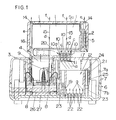
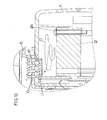
- the charger according to the present invention comprises a battery pack 2, in which a plurality of batteries 1 are disposed on a battery fixing plate 20 provided within a battery pack case 5.
- batteries nickel-cadmium battery or nickel-hydrogen battery, for example, is employed.
- the battery pack case 5 is provided at its bottom side wall with a projection 4 having on its periphery contacting terminals 13, and with a plurality of vent ports 10 formed at positions not overlapping with the projection 4. These vent ports 10 are forming first vent ports provided in correspondence with later described blast ports 11 of a charge section 6.
- the vent ports 10 respectively have an internally opposing member for directing air current entering from downward opening of the respective ports to be dispersed once sideward and then into the interior of the battery pack 5, as shown by arrows "c" in FIG. 1.
- a plurality of discharge ports 14 are formed, at least part of which ports 14 being regarded as second vent ports.
- the discharge ports 14 include ones which are formed in peripheral walls of the battery pack case 5 (not shown), and these discharge ports 14 are provided respectively to oppose each clearance 15 between the respective batteries 1 as well as each clearance 16 between the respective batteries 1 and the battery pack case 5, so that air flow blasted through the vent ports 10 into the battery pack case 5 passes through these clearances 15 and 16 and is then discharged from the discharge ports 14.
- a charger case 7 has a mounting hole 9 indented from a top side wall to open upward, and blast ports 11 at positions in the top side wall opposing the vent ports 10 of the battery pack case 5.
- This charger case 7 comprises upper and lower case halves 7a and 7b, and the upper case half 7a is formed to have the mounting hole 9 for receiving the projection 4 of the battery pack 2, as well as the blast ports 11 opposing the vent ports 10 of the battery pack 2.
- the blast ports 11 are provided as passed vertically through a thickened part formed in the top side wall of the upper case half 7a, in the present embodiment as seen in FIGS. 1 and 3a.
- the respective blast ports 11 are slanted at lower, inward openings toward the center of a blast side of a blower 12 disposed below the blast ports 11, while upper, outward openings of the blast ports 11 extend vertically, and top ends of these blast ports 11 oppose respectively each downward end of the respective vent ports 10 of the battery pack 2, whereby the top ends of the blast ports 11 and the downward ends of the vent ports 10 are brought into communication with each other in a state where the projection 3 of the battery pack 2 is mounted into the mounting hole 9 of the charger section 6, and relatively a much more amount of air can be blown from the blower 12 into the battery pack 2.
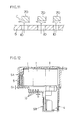
- a plurality of intake ports 22 are formed to intake exterior air into the case 7, as shown in FIGS. 1 and 3b.
- Screw cylinders 23 are provided on the bottom wall around the intake ports 22 for fixing the blower 12, so that the blower 12 can be fixed inside the lower case half 7b by screwing screws 24 through screw holes 25 into the screw cylinders 23.
- the blower 12 is disposed to be substantially intermediate position in vertical direction of the charger case 7, and a predetermined upper clearance is defined between the blast ports 11 and the blower 12, while a predetermined lower clearance 19 is defined between the blower 12 and the intake ports 22.
- blower 12 is disposed on a side position of the mounting hole 9, and interior space of the mounting hole 9 is made to communicate with the intake side of the blower 12, whereby any hydrogen has generated around charging terminals 8 disposed inside the mounting hole 9 can be sucked by the blower 12 so as to be discharged through the blast and vent ports 11 and 10 and discharge ports 14 of the battery pack 2 to the exterior.
- the charging terminals 8 inside the mounting hole 9 are so disposed that, upon mounting of the projection 4 of the battery pack 2 into the mounting hole 9, the contacting terminals 3 come into contact with the charging terminals 8, and the charging of the batteries 1 inside the battery pack 2 is performed.
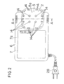
- the charger section 6 includes a printed circuit board 26 to which the charging terminals 8 are properly mounted, a resin molded part 27 and a power-source connector cord 28 (see FIGS. 1 and 2).
- a charging circuit (heat generating circuit parts) illustration of which is omitted is disposed at different position from that of the blower 12, mounting hole 9 and charging terminals 8 in the charger case 7.
- the charging is started.
- the vent ports 10 provided in the wall on which the projection 4 is formed in the battery pack case 5 are brought into conformity to the blast ports 11 in the top wall of the charger case 7, and the blower 12 in the charger case 7 actuated sucks the exterior air from the intake ports 22 of the charger case 7 in a direction shown by arrows "a" in FIG.
- the arrangement is so made that, when the projection 4 is mounted in the mounting hole 9, the vent ports 10 of the battery pack 2 can be positioned to oppose the blast ports 11 of the charger section 6, and the blown air of the blower 12 can be transmitted through the blast ports 11 and vent ports 10 efficiently into the battery pack 2 at a relatively high flow rate. Further, the blower 12 is positioned as separated from the blast ports 11, so that the blown air can be accumulated in the clearance 17 between the blower 12 and the blast ports 11, the blown air rate of the blower 12 can be further increased, and eventually the plurality of the batteries 1 in the battery pack 2 can be fully and highly efficiently cooled by the blown air of the blower 12.
- any of such trouble as internal short-circuit, capacity drop or the like can be reliably prevented from occurring during the charging, any trouble occurrence can be eliminated even when the batteries 1 are charged immediately after being used at a high load, and an accelerated charging is made possible without temporary interruption of the charging due to a temperature sensor and eliminating any loss-time for the charging.
- the blower 12 is disposed on a side position of the mounting hole 9 in which the charging terminals 8 are provided, the hydrogen gas even generated from such batteries 1 as the nickel-cadmium or nickel-hydrogen batteries during the charging and accumulated around the charging terminals 8 present at generating source of the hydrogen gas can be sucked by the blower 12 to efficiently discharge, with a sufficiently elevated gas discharging effect. Accordingly, it is enabled to prevent a stagnation of the hydrogen gas from occurring around the charging terminals 8 or within the batteries 1, such flashing of hydrogen gas as has been occurring conventionally can be prevented completely, and the safetyness can be sufficiently elevated.
- vent ports 10 and discharge parts 14 in the wall of the battery pack 2 on the side facing the charger section 6 and in the wall opposite to the former any air caused to be warmed by the hydrogen gas or by generated heat of the batteries and to ascend will not be allowed to accumulate inside the battery pack 2 but to be effectively discharged to the exterior, so as to elevate the cooling effect.
- the respective vent ports 10 are formed in vertical direction and the internally opposing member of these vent ports 10 render the blasted air from the ports to be dispersed sideward, the airflow led inside the battery pack 2 is made to fluidize between the respective batteries 1 as well balanced, so that the plurality of batteries can be eventually cooled uniformly to further elevate the cooling effect and the effect of discharging the hydrogen gas can be also elevated simultaneouly.
- the battery pack 2 is provided to be mounted and dismounted as shifted in vertical direction, and the blast ports 11 on the side of the charger section 6 are made in the wall which faces the battery pack 2 in such vertical shifting direction of the pack for intimate engagement with the vent ports 10 of the battery pack 2, so that much more air can be transmitted into the battery pack 2 through the intimately engaging ports 10 and 11. Further, by the provision of the vent and blast ports 10 and 11 in the vertically engaging walls, their intimate engagement can be assured even when the charger section 6 and battery pack 2 involve certain dimensional fluctuation.
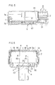
- FIGS. 4 and 5 there is shown another embodiment of the present invention, in which a shielding wall part 31 is provided between the heat generating circuit parts and the blower 12 both provided in the charger section 6 for shielding heat, while no shield is provided between the blower 12 and the charging terminals 8 of the mounting hole 9 provided in the charger section 6.
- a printed circuit board 50 on which the heat generating circuit parts are mounted is provided in the charger section 6.
- Other constituents are the same as those in FIG. 1 and are denoted in FIGS. 4 and 5 by the same reference symbols as those used in FIG. 1. In this embodiment, as seen in FIG.
- a heat shielding partition 30 is formed integral internally with the upper case half 7a in an L-shape in plan view, and one leg part of this L-shape partition 30 where no notch or aperture is made is used as the shielding wall part 31, whereas the other leg part of the partition 30 is made to be a wall part 32 having a plurality of notches 33.
- two of the notches 33 are provided in the wall part 32, which number may be properly increased or decreased.
- the heat shielding wall part 31 between the blower 12 and the heat generating circuit parts provided in the charger section 6, it is possible to prevent air warmed up by the generated heat of such charging circuit part as the transformer from being transmitted toward the battery pack 2.
- the heat transmission from the blower 12 can be thus made less, the blown air current of the blower 12 can be maintained to be low in the temperature, and the cooling effect with respect to the batteries 1 can be elevated.
- the notches 33 in the wall part 32 between the charging terminals 8 and the blower 12 air current between the charging terminals 8 and the blower 12 is not intercepted but can be rather promoted by the notches 33.
- the arrangement is so made that the heat of the heat generating circuit parts can be shielded by the shielding wall part 31 of the partition 30, so that, upon generation of the hydrogen gas at the batteries 1, the hydrogen gas around the charging terminals 8 at the gas generating source can be sucked by the blower 12 through the notches 33 as shown by arrows "j" in FIG. 4a, and the gas discharge effect can be elevated.
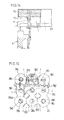
- the battery pack case 5 is provided at an interior vent opening 10 of the projection 4 with a rib 13 for reflecting the air current caused to be in diagonal direction due to the slant of the vanes in the blower 12, so that the rib 13 will constitute an air diffuser means.
- Other constituents are the same as those in FIG. 1.
- the air current caused by the blower 12, for example, will be in diagonal direction in accordance with the slant of the rotating vanes as shown in FIGS. 4 and 5 by arrows "g" in FIGS. 4 and 5 because of operating characteristics of fans.
- the interior vent opening 10 of the projection 4 When the interior vent opening 10 of the projection 4 is formed in a single large aperture, it is possible to cool the batteries 1a positioned in the direction of blown air current, whereas the batteries 1b positioned not in the direction of blown air current will be apt to be lowered.
- the rib 13 is erected along a side periphery of the vent opening 10 inside the battery pack 2 for reflecting the diagonal air current.
- This rib 13 is so constituted that, in the diagonal air currents "h” and “i” led in from the vent ports 10, the diagonal air current "h” can be prevented from being deviated into a clearance 18 defined between the batteries 1a disposed edgewise and the bottom side of the battery pack case 5, and the rib 13 has a height set to be effective to cause the diagonal air current "h” reflected thereon to be led uniformly to the respective batteries 1a and 1b. Accordingly, even when the vent opening 10 is formed with the single large aperture, the air current "h” is made to reflect on the rib 13 so as to flow as well balanced into the clearance 16 between the respective batteries 1, as shown by arrows "d” and "e” in FIG.
- the discharge ports 14 are pvovided in the top wall 5a opposite to the bottom wall 5c in which the vent ports 10 are made, and in peripheral side wall 5b at positions closer to the top wall 5a, respectively of the battery pack case 5, and these discharge ports 14 are respectively opposed to the clearances 15 between the respective batteries 1 and the clearances 16 between the batteries 1 and the case 5.
- the vent ports 10 in the bottom wall 5c of the case 5 are provided to open in a plurality (for example, four) of slits, as shown in FIG. 7a, and the discharge ports 14 made in the peripheral side wall 5b of the case 5 are opened in a rectangular shape at the positions closer to the top wall 5a of the case 5, as shown in FIG. 8a.
- the discharge ports 14 in the top wall 5a include many outer peripheral discharge ports 14a provided along the outer periphery of the top wall of the case 5, and a plurality (for example, four) of central discharge ports 14b provided in the central part.
- the outer peripheral discharge ports 14a are respectively disposed to oppose each clearance 16 between the batteries 1 and the case 5, while the central discharge ports 15b are respectively disposed to oppose each clearance 15 between the respective batteries 1. While in the present embodiment the discharge ports 14 are shown to be provided in both of the top and side walls 5a and 5b of the case 5, these ports are not always required to be provided in both walls, but it is possible to have only one of the top and side walls 5a and 5b provided with the discharge ports 14.
- the blast air from the vent ports 10 into the battery pack case 5 flows into the clearances 15 between the respectivel batteries 1 and into the clearances 16 between the batteries 1 and the case 5, and is then discharged out of the discharge ports 14a and 14b in the top wall 5a and in the side wall 5b at closer positions to the top wall 5a of the case 5. Therefore, the blast air is made to readily reach all zones in the interior of the battery pack 2, and can sufficiently fluidize effectively with respect to the batteries 1. Further, as the discharge ports 14a and 14b are provided in the top wall 5a and side wall 5b at closer positions to the top wall of the battery pack case 5 so as to be remote from the vent ports 10, the blast air led in from the vent ports 10 can be prevented from being discharged immediately out of the discharge ports.
- the blown air by the blower 12 can be further fully distributed to the respective batteries 1, as a result of which the respective batteries 1 can be fully and uniformly cooled, it does not require any long time until the full discharge of the hydrogen gas but requires only a short time therefor, and any risk of causing the hydrogen gas to remain without being fully discharged can be eliminated.
- a battery fixing plate 20 is formed to have apertures 35 made respectively at positions opposing the clearances 15 between the batteries 1, and ventholes 36 made respectively at positions opposing axial metal part of each battery 1, and the fixing plate 20 is also formed to be separated at outer peripheral edge from inner periphery of the side wall of the battery pack case 5. Accordingly, the blown air by the blower 12 can be made to fluidize through the apertures 35 of the battery fixing plate 20 and into the clearances 15 between the batteries 1, and simultaneously the air can be applied through the ventholes 36 to the metal parts, so that the metal parts of the batteries 1 can be directly cooled.
- a gap 60 made by the separation of the outer peripheral edge of the battery fixing plate 20 from the inner periphery of the battery pack case 5 is axially opposing the clearances 16 between the batteries 1 and the case 5, the blast air can be also fully fluidized in the clearances 16 between the batteries 1 and the case 5, and the cooling effect for the batteries 1 can be further improved.
- the provision of the gap 60 between the outer peripheral edge of the battery fixing plate 20 and the inner periphery of the case 5 allows no further aperture or apertures required to be made at the position opposing the gap 60, and the battery fixing plate 20 can be made simpler in its structure.
- FIG. 10 shows the air flow in the arrangement in which the center of the blower 12 is deviated from the vent ports 10 of the battery pack 2.
- the blown air B from the blower 12 expands spirally from the center of the blower 12, and blown air B is made stronger on outer peripheral side of the blower 12. That is, a higher blown air pressure is occurring on the outer side of the center of the blower 12, this outer blown air at the higher pressure can be transmitted from the blast ports 11 positioned deviated from the center of the blower 12 to the vent ports 10 of the battery pack 2, and the transmitting air flow rate to the pack 2 can be further increased.
- the blast-air dispersing members provided inside the vent ports 10 are formed in the form of ribs 70 opposing the ports 10, for preventing the blast airflow from linearly directly entering into the battery pack 2, which ribs 70 are formed in a lattice shape, covering the ports 10 with an inward gap. Accordingly, the airflows entered through the vent port 10 into the pack 2 are caused by the ribs 70 to be dispersed in the direction of arrows C, whereby the airflows can be prevented from directly entering into the pack 2 but can be expanded. With such ribs 70, it is also possible to prevent any dust or such foreign matter as a nail from entering into the battery pack 2.
- vent ports 10 of the battery pack 2 are referred to as being opened in vertical direction, they may be not required to be limited to of such vertical ports, but it will be also possible to form the vent ports 10, for example, diagonally through the wall of the battery pack case 5.
- the vent ports 10 are opened in diagonally upward direction, so as to be able to disperse the airflow, while preventing such foreign matter as the nail from being inserted into the battery pack 2, so as not to allow the nail to directly hit the batteries.
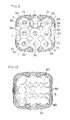
- the battery pack 2 is formed to have, in addition to the vent ports 10 made in the same bottom wall as that having the projection 4 and the discharge ports 14 in the opposite top wall of the battery pack case 5, bottom and top clearances G1 and G2 forming ventilation paths lying between the bottom wall and the batteries 1 and between the top wall and the batteries 1, respectively, in a direction intersecting blowing direction and in parallel to the top and bottom walls of the case 5.
- the airflow entered into the battery pack 2 is caused, therefore, to expand first through the bottom clearance G1 over the whole of the interior of the battery pack 2, then through the clearances between the respective batteries and between the batteries 1 and the case 5 to reach the top clearance G2 on the top side of the case 5, and to be eventually discharged through the discharge ports 14.
- the top clearance G2 may be formed between the top wall of the case 5 and the battery fixing plate 20 as in FIG. 12, by providing to the plate 20 arcuate ribs 80 protruded inward at a plurality of positions as mutually spaced and at the same height. It is also possible to form the clearance G1 by providing similar ribs so as to project on the bottom wall of the case 5.
- the top and bottom clearances are formed to have a cross sectional area larger than that of the vent ports 10 (Sx4 in the case of FIG. 12) of the battery pack 2.
- the top and bottom clearances are effective to prevent a spread of the airflow widely dispersed as blasted through the vent ports 10 from being restricted.
- FIG. 12 shows the battery pack case 5 comprising upper and lower case halves 5A and 5B, the invention is not always limited to this structure of the case 5.
- the temperature detecting means 71 may be, for example, a temperature sensor, thermoswitch of the like.
- the temperature sensor 71 here is disposed in one clearance between a pair of the batteries 1 and is enclosed in a cushion member 72 which in turn is held against the batteries with a tape 73 wound or adhered to the batteries, so that the non-ventilative space is defined by the cushion member 72, in which space the temperature sensor 71 is disposed.
- the temperature sensor 71 As the temperature of the batteries 1 is to be detected by the temperature sensor 71 or the like disposed in the non-ventilative space, it is enabled to directly detect the battery temperature, to prevent the temperature sensor 71 from being hit by the airflow transmitted into the battery pack 2, and to accurately detect the battery temperature. Even in an event where any external shock is given to the battery pack 2, such shock may be absorbed by the cushion member 72, and the temperature sensor 71 can be sufficiently protected.
- the arrangement for holding the temperature sensor 71 may not be limited to the one of this embodiment in FIG. 14.
- the non-ventilative space is formed by utilizing connector plates 76 each connecting mutually a pair of electrodes of adjacent ones of the batteries 1, a central part 76a of one of which connector plates 76 is disposed to substantially close one of the center side apertures 35 made in the battery fixing plate 20, while the apertures 35 communicate with the clearances between the respective batteries 1, and the non-ventilative space can be readily formed by closing one of the apertures 35 so as to shield the clearance communicating with this aperture 35.
- the non-ventilative space is formed in one of the clearances between the respective batteries 1, that is, the space is one clearance surrounded by the batteries, so that the ventilation is further difficult, and the temperature of batteries 1 can be further accurately detected.
Landscapes
- Engineering & Computer Science (AREA)
- Power Engineering (AREA)
- Chemical & Material Sciences (AREA)
- Chemical Kinetics & Catalysis (AREA)
- Electrochemistry (AREA)
- General Chemical & Material Sciences (AREA)
- Secondary Cells (AREA)
- Battery Mounting, Suspending (AREA)
- Charge And Discharge Circuits For Batteries Or The Like (AREA)
Applications Claiming Priority (3)
| Application Number | Priority Date | Filing Date | Title |
|---|---|---|---|
| JP32262197 | 1997-11-25 | ||
| JP6912298A JP4314641B2 (ja) | 1997-11-25 | 1998-03-18 | 充電装置 |
| EP98203974A EP0920105B1 (de) | 1997-11-25 | 1998-11-25 | Lader |
Related Parent Applications (1)
| Application Number | Title | Priority Date | Filing Date |
|---|---|---|---|
| EP98203974A Division EP0920105B1 (de) | 1997-11-25 | 1998-11-25 | Lader |
Publications (2)
| Publication Number | Publication Date |
|---|---|
| EP1791237A2 true EP1791237A2 (de) | 2007-05-30 |
| EP1791237A3 EP1791237A3 (de) | 2008-08-27 |
Family
ID=26410309
Family Applications (2)
| Application Number | Title | Priority Date | Filing Date |
|---|---|---|---|
| EP98203974A Expired - Lifetime EP0920105B1 (de) | 1997-11-25 | 1998-11-25 | Lader |
| EP07104305A Withdrawn EP1791237A3 (de) | 1997-11-25 | 1998-11-25 | Lader |
Family Applications Before (1)
| Application Number | Title | Priority Date | Filing Date |
|---|---|---|---|
| EP98203974A Expired - Lifetime EP0920105B1 (de) | 1997-11-25 | 1998-11-25 | Lader |
Country Status (4)
| Country | Link |
|---|---|
| US (3) | US6218807B1 (de) |
| EP (2) | EP0920105B1 (de) |
| JP (1) | JP4314641B2 (de) |
| DE (1) | DE69839296T2 (de) |
Families Citing this family (64)
| Publication number | Priority date | Publication date | Assignee | Title |
|---|---|---|---|---|
| US5553675A (en) | 1994-06-10 | 1996-09-10 | Minnesota Mining And Manufacturing Company | Orthopedic surgical device |
| US6455186B1 (en) | 1998-03-05 | 2002-09-24 | Black & Decker Inc. | Battery cooling system |
| JP3569152B2 (ja) | 1998-10-15 | 2004-09-22 | 株式会社マキタ | バッテリーパック |
| DE10003247B4 (de) * | 1999-01-29 | 2005-02-24 | Sanyo Electric Co., Ltd., Moriguchi | Stromquelle, versehen mit wiederaufladbaren Batterien |
| JP4147567B2 (ja) | 1999-02-26 | 2008-09-10 | 日立工機株式会社 | 電池の充電装置 |
| US6656626B1 (en) | 1999-06-01 | 2003-12-02 | Porter-Cable Corporation | Cordless power tool battery release mechanism |
| JP3742261B2 (ja) | 1999-11-10 | 2006-02-01 | 株式会社マキタ | 電動工具用バッテリーパック |
| JP3741359B2 (ja) | 1999-11-11 | 2006-02-01 | 株式会社マキタ | バッテリーパック |
| JP3778262B2 (ja) * | 2000-12-21 | 2006-05-24 | 株式会社マキタ | 充電方式及び電池パック |
| JP3826724B2 (ja) * | 2001-04-06 | 2006-09-27 | 日立工機株式会社 | 充電機能付き電源装置 |
| CN101262080B (zh) * | 2001-11-09 | 2010-11-10 | 密尔沃基电动工具公司 | 电池充电器和使用动力工具电池的电子元件 |
| US7332889B2 (en) * | 2001-11-09 | 2008-02-19 | Milwaukee Electric Tool Corporation | Battery charger |
| EP1465947A4 (de) * | 2001-12-13 | 2005-11-30 | Exxonmobil Chem Patents Inc | Thermoplastische vulkanisate für pannenlauffähige reifen |
| US6812656B2 (en) * | 2002-02-27 | 2004-11-02 | Railpower Technologies Corp. | Sequenced pulse width modulation method and apparatus for controlling and powering a plurality of direct current motors |
| JP4272387B2 (ja) * | 2002-05-22 | 2009-06-03 | パナソニック株式会社 | 組電池の冷却装置 |
| EP1381134B1 (de) | 2002-07-12 | 2011-11-16 | HILTI Aktiengesellschaft | Akkubatterie-Ladestation |
| CA2411132A1 (en) * | 2002-11-05 | 2004-05-05 | Railpower Technologies Corp. | Direct turbogenerator |
| JP4314044B2 (ja) * | 2003-03-18 | 2009-08-12 | パナソニックEvエナジー株式会社 | 電池パック |
| EP1475876B1 (de) * | 2003-05-03 | 2011-01-05 | Metabowerke GmbH | Ladegerät für einen Akkupack, sowie Anordnung aus Ladegerät und Akkupack |
| EP1487080A1 (de) * | 2003-05-21 | 2004-12-15 | Kolvin Industries Ltd | Batterielader |
| US7189473B2 (en) * | 2003-06-03 | 2007-03-13 | Eastway Fair Company Limited | Battery venting system |
| CA2537037A1 (en) | 2003-08-26 | 2005-04-07 | Railpower Technologies Corp. | A method for monitoring and controlling locomotives |
| JP3979981B2 (ja) * | 2003-08-29 | 2007-09-19 | 三洋電機株式会社 | 充電器 |
| US7064507B2 (en) * | 2004-02-17 | 2006-06-20 | Railpower Technologies Corp. | Managing wheel skid in a locomotive |
| WO2005084335A2 (en) * | 2004-03-01 | 2005-09-15 | Railpower Technologies Corp. | Cabless hybrid locomotive |
| WO2005086910A2 (en) * | 2004-03-08 | 2005-09-22 | Railpower Technologies Corp. | Hybrid locomotive configuration |
| WO2005097573A2 (en) * | 2004-03-30 | 2005-10-20 | Railpower Technologies Corp. | Emission management for a hybrid locomotive |
| WO2005114811A2 (en) * | 2004-05-17 | 2005-12-01 | Railpower Technologies Corp. | Design of a large battery pack for a hybrid locomotive |
| WO2006020667A2 (en) * | 2004-08-09 | 2006-02-23 | Railpower Technologies Corp. | Locomotive power train architecture |
| WO2006020587A2 (en) * | 2004-08-09 | 2006-02-23 | Railpower Technologies Corp. | Regenerative braking methods for a hybrid locomotive |
| WO2006028638A2 (en) * | 2004-09-03 | 2006-03-16 | Railpower Technologies Corp. | Multiple engine locomotive configuration |
| US7601458B2 (en) | 2005-03-24 | 2009-10-13 | Samsung Sdi Co., Ltd. | Rechargeable battery and battery module |
| EP1878110A2 (de) * | 2005-04-25 | 2008-01-16 | Railpower Technologies Corp. | Lokomotivensteuerung mit mehreren primärantriebsquellen |
| US8375067B2 (en) * | 2005-05-23 | 2013-02-12 | Monster Worldwide, Inc. | Intelligent job matching system and method including negative filtration |
| EP1742323A1 (de) * | 2005-07-05 | 2007-01-10 | Sony Ericsson Mobile Communications AB | Überdruckventil für einen Batterielader |
| WO2007047809A2 (en) * | 2005-10-19 | 2007-04-26 | Railpower Technologies Corp. | Design of a large low maintenance battery pack for a hybrid locomotive |
| JP4905852B2 (ja) * | 2006-09-07 | 2012-03-28 | 日立工機株式会社 | 充電器 |
| US20080288132A1 (en) | 2007-05-16 | 2008-11-20 | General Electric Company | Method of operating vehicle and associated system |
| DE102007031857A1 (de) * | 2007-07-09 | 2009-01-15 | Robert Bosch Gmbh | Akkumulator |
| US10721533B2 (en) | 2007-11-30 | 2020-07-21 | Hsni, Llc | Method and system for displaying and updating electronic information on a display device |
| US20100138875A1 (en) | 2007-11-30 | 2010-06-03 | Johnson Gerard C | Method and system for improved interactive television processing |
| US8080972B2 (en) * | 2008-06-02 | 2011-12-20 | Goal Zero Llc | System and method for storing and releasing energy |
| US8980457B2 (en) * | 2010-11-04 | 2015-03-17 | Samsung Sdi Co., Ltd. | Battery module |
| US8852789B2 (en) | 2010-11-04 | 2014-10-07 | Samsung Sdi Co., Ltd. | Battery module having battery cell holder |
| JP5512505B2 (ja) * | 2010-12-24 | 2014-06-04 | 三洋電機株式会社 | 電源装置及びこれを備える車両 |
| US9114181B2 (en) | 2011-03-30 | 2015-08-25 | Covidien Lp | Process of cooling surgical device battery before or during high temperature sterilization |
| US10340709B2 (en) * | 2011-07-29 | 2019-07-02 | Lightening Energy | Electric battery rapid recharging system including a mobile charging station having a coolant supply line and an electrical supply line |
| JP5341156B2 (ja) * | 2011-09-06 | 2013-11-13 | 三洋電機株式会社 | 電源装置 |
| JP5676543B2 (ja) | 2011-10-07 | 2015-02-25 | ミルウォーキー エレクトリック ツール コーポレーションMilwaukee Electric Toolcorporation | 電池組立体 |
| PT106793B (pt) * | 2013-02-20 | 2021-02-11 | Novadelta Comercio E Ind De Cafes Lda | Máquina de preparação de bebidas com meios de armazenamento de energia |
| US20150302487A1 (en) * | 2014-04-17 | 2015-10-22 | Ericsson Television Inc. | Method and arrangement for providing adaptive bitrate-dynamic advertisements |
| DE102014012869A1 (de) * | 2014-08-29 | 2016-03-03 | Andreas Stihl Ag & Co. Kg | Ladegerät für einen Akkupack |
| CN106160036B (zh) * | 2015-03-30 | 2019-02-01 | 南京德朔实业有限公司 | 充电器、充电组合以及带电池包的电动工具 |
| US20170049004A1 (en) * | 2015-08-10 | 2017-02-16 | Yu-Wen Tsai | Heat Dissipation Device With Charging Function |
| US11916415B2 (en) * | 2015-11-09 | 2024-02-27 | Gogoro Inc. | Systems and apparatus for charging portable electrical energy storage devices |
| JP6835084B2 (ja) * | 2016-05-31 | 2021-02-24 | 工機ホールディングス株式会社 | 充電装置 |
| JP7358167B2 (ja) * | 2019-09-30 | 2023-10-10 | 株式会社マキタ | 電池パック |
| KR102813064B1 (ko) | 2019-12-03 | 2025-05-26 | 밀워키 일렉트릭 툴 코포레이션 | 배터리 팩 및 충전기 시스템 |
| US11592166B2 (en) | 2020-05-12 | 2023-02-28 | Feit Electric Company, Inc. | Light emitting device having improved illumination and manufacturing flexibility |
| US11876042B2 (en) | 2020-08-03 | 2024-01-16 | Feit Electric Company, Inc. | Omnidirectional flexible light emitting device |
| WO2022065211A1 (ja) * | 2020-09-25 | 2022-03-31 | 三洋電機株式会社 | 電池モジュール |
| CN112768828B (zh) * | 2020-12-30 | 2022-03-11 | 国网山东省电力公司高青县供电公司 | 温度自调节式电力供电设备 |
| WO2023283429A1 (en) | 2021-07-08 | 2023-01-12 | Milwaukee Electric Tool Corporation | Power tool system |
| CN115257421A (zh) * | 2022-09-28 | 2022-11-01 | 徐州市恒源电器有限公司 | 一种便于使用的新能源汽车用多功能充电器 |
Family Cites Families (34)
| Publication number | Priority date | Publication date | Assignee | Title |
|---|---|---|---|---|
| US4313080A (en) * | 1978-05-22 | 1982-01-26 | Battery Development Corporation | Method of charge control for vehicle hybrid drive batteries |
| JPS60187456A (ja) | 1984-03-08 | 1985-09-24 | Kobe Steel Ltd | 鋳型内湯面レベルの検出素子 |
| JPH0537634Y2 (de) * | 1987-01-27 | 1993-09-22 | ||
| JPS6454259U (de) * | 1987-09-25 | 1989-04-04 | ||
| JP2636884B2 (ja) * | 1988-05-14 | 1997-07-30 | 松下電工株式会社 | 充電装置 |
| US5206576A (en) * | 1989-11-22 | 1993-04-27 | Motorola, Inc. | Battery charger |
| US5015545A (en) * | 1990-01-03 | 1991-05-14 | General Motors Corporation | Method and apparatus for cooling an array of rechargeable batteries |
| US5148094A (en) * | 1990-08-10 | 1992-09-15 | Black & Decker Inc. | Charger with universal battery pack receptacle |
| DE4026020C1 (en) * | 1990-08-17 | 1991-12-12 | Hella Kg Hueck & Co, 4780 Lippstadt, De | Transportable battery charging appts. esp. for vehicle - has ventilation holes in opposite sidewalls between cooling ribs of power section and panel for operating elements and display |
| NO176942C (no) | 1991-02-08 | 1995-06-28 | Chinet Co | Beholder for plantevekst og fremgangsmåte for fremstilling av slik beholder |
| JPH0717631Y2 (ja) | 1991-03-09 | 1995-04-26 | 須川工業株式会社 | 台 車 |
| JPH04358950A (ja) * | 1991-05-31 | 1992-12-11 | Honda Motor Co Ltd | 電動式車両 |
| US5229702A (en) * | 1991-06-26 | 1993-07-20 | Boehling Daniel E | Power system battery temperature control |
| JPH0537634A (ja) | 1991-07-26 | 1993-02-12 | Nec Corp | 構内交換機 |
| US5204609A (en) * | 1991-12-16 | 1993-04-20 | Alisauski Daryl J | Battery cooling apparatus |
| JPH05169981A (ja) * | 1991-12-20 | 1993-07-09 | Honda Motor Co Ltd | 電気自動車におけるバッテリ冷却装置 |
| EP0552737A1 (de) * | 1992-01-22 | 1993-07-28 | Hughes Aircraft Company | Wetterfester längsseitiger Lader |
| JPH0584023U (ja) | 1992-04-10 | 1993-11-12 | 日立工機株式会社 | ガス抜き穴付蓄電池 |
| JPH0654209A (ja) | 1992-08-03 | 1994-02-25 | Mitsubishi Electric Corp | 画像圧縮・伸長回路 |
| JPH06150978A (ja) | 1992-11-02 | 1994-05-31 | Shibaura Eng Works Co Ltd | 充電器 |
| JPH0654209U (ja) | 1992-12-22 | 1994-07-22 | 三洋電機株式会社 | 充電システム |
| US5721064A (en) * | 1993-04-30 | 1998-02-24 | Aer Energy Resources Inc. | Air manager system for reducing gas concentrations in a metal-air battery |
| US5560999A (en) * | 1993-04-30 | 1996-10-01 | Aer Energy Resources, Inc. | Air manager system for recirculating reactant air in a metal-air battery |
| JPH0785896A (ja) * | 1993-09-13 | 1995-03-31 | Sony Corp | 2次電池パック及びその充電装置 |
| JP2758348B2 (ja) | 1993-10-01 | 1998-05-28 | 内浜化成株式会社 | バッテリーキャリヤ・カバー構造 |
| DE4407156C1 (de) * | 1994-03-04 | 1995-06-08 | Deutsche Automobilgesellsch | Batteriekasten |
| JPH08128901A (ja) * | 1994-10-31 | 1996-05-21 | Sanyo Electric Co Ltd | 温度センサーとパック電池 |
| JP3136926B2 (ja) * | 1994-11-08 | 2001-02-19 | 松下電器産業株式会社 | 蓄電池の状態管理システム |
| JP3492045B2 (ja) * | 1994-12-07 | 2004-02-03 | 本田技研工業株式会社 | 充電器 |
| DE19607226A1 (de) * | 1996-02-27 | 1997-09-04 | Metabowerke Kg | Akku-Ladegerät für Elektrohandwerkzeuge |
| JPH09266016A (ja) * | 1996-03-27 | 1997-10-07 | Toyota Autom Loom Works Ltd | 円筒型電池の冷却方法 |
| US5883491A (en) * | 1997-03-06 | 1999-03-16 | Silverman; Martin S. | Method and apparatus for depositing an electrical charge to an electrical storage cell used in an automobile |
| US5856037A (en) * | 1997-07-07 | 1999-01-05 | Optima Batteries, Inc. | Battery venting system and method |
| US5991665A (en) * | 1997-09-18 | 1999-11-23 | Sulzer Intermedics Inc. | Self-cooling transcutaneous energy transfer system for battery powered implantable device |
-
1998
- 1998-03-18 JP JP6912298A patent/JP4314641B2/ja not_active Expired - Fee Related
- 1998-11-25 EP EP98203974A patent/EP0920105B1/de not_active Expired - Lifetime
- 1998-11-25 EP EP07104305A patent/EP1791237A3/de not_active Withdrawn
- 1998-11-25 DE DE69839296T patent/DE69839296T2/de not_active Expired - Lifetime
- 1998-11-25 US US09/199,375 patent/US6218807B1/en not_active Expired - Lifetime
-
2001
- 2001-01-31 US US09/772,868 patent/US6339312B2/en not_active Expired - Lifetime
- 2001-01-31 US US09/772,860 patent/US6342773B2/en not_active Expired - Lifetime
Also Published As
| Publication number | Publication date |
|---|---|
| US20010004199A1 (en) | 2001-06-21 |
| US20010004200A1 (en) | 2001-06-21 |
| US6342773B2 (en) | 2002-01-29 |
| US6339312B2 (en) | 2002-01-15 |
| EP0920105B1 (de) | 2008-03-26 |
| US6218807B1 (en) | 2001-04-17 |
| DE69839296D1 (de) | 2008-05-08 |
| JPH11219733A (ja) | 1999-08-10 |
| EP0920105A3 (de) | 2000-01-19 |
| EP0920105A2 (de) | 1999-06-02 |
| EP1791237A3 (de) | 2008-08-27 |
| JP4314641B2 (ja) | 2009-08-19 |
| DE69839296T2 (de) | 2009-04-09 |
Similar Documents
| Publication | Publication Date | Title |
|---|---|---|
| EP0920105B1 (de) | Lader | |
| US12334582B2 (en) | Upper cover assembly and battery pack | |
| US12294107B2 (en) | Battery pack | |
| US12074338B2 (en) | Battery pack | |
| US7189473B2 (en) | Battery venting system | |
| KR102916626B1 (ko) | 리무버블 퓨즈 어셈블리를 구비한 배터리 모듈 및 이를 포함하는 배터리 팩 | |
| WO2021075780A1 (ko) | 배터리 팩 및 전자 디바이스 및 자동차 | |
| KR20210067663A (ko) | 배터리 팩 | |
| WO2022158783A1 (ko) | 배터리 팩 | |
| WO2020145530A1 (ko) | 내부 플레이트를 포함한 배터리 모듈 | |
| JP2003045384A (ja) | 電池モジュール | |
| WO2014185732A1 (ko) | 배터리 패키지 | |
| EP4510353A1 (de) | Batterie und elektrische vorrichtung | |
| JP5033107B2 (ja) | 充電装置 | |
| JP4250785B2 (ja) | 充電装置 | |
| JP2003143766A (ja) | 充電装置 | |
| JPH0537634Y2 (de) | ||
| JP3285345B2 (ja) | 充電装置 | |
| JP4568086B2 (ja) | パック電池 | |
| WO2019008899A1 (ja) | 電池装置 | |
| JP3354561B2 (ja) | 充電装置 | |
| JP2006040625A (ja) | 車両用の電源装置 | |
| JP2000058138A (ja) | 電池パック冷却機能付充電器 | |
| CN221862448U (zh) | 电池充电器 | |
| US20240120756A1 (en) | Battery charger |
Legal Events
| Date | Code | Title | Description |
|---|---|---|---|
| PUAI | Public reference made under article 153(3) epc to a published international application that has entered the european phase |
Free format text: ORIGINAL CODE: 0009012 |
|
| AC | Divisional application: reference to earlier application |
Ref document number: 0920105 Country of ref document: EP Kind code of ref document: P |
|
| AK | Designated contracting states |
Kind code of ref document: A2 Designated state(s): DE |
|
| RIN1 | Information on inventor provided before grant (corrected) |
Inventor name: SUZUKI, KAZUHIRO Inventor name: OHASHI, TOSHIHARU Inventor name: SAKAUE, MASAAKI |
|
| PUAL | Search report despatched |
Free format text: ORIGINAL CODE: 0009013 |
|
| AK | Designated contracting states |
Kind code of ref document: A3 Designated state(s): DE |
|
| 17P | Request for examination filed |
Effective date: 20081105 |
|
| 17Q | First examination report despatched |
Effective date: 20081211 |
|
| RAP1 | Party data changed (applicant data changed or rights of an application transferred) |
Owner name: PANASONIC ELECTRIC WORKS CO., LTD. |
|
| AKX | Designation fees paid |
Designated state(s): DE |
|
| RAP1 | Party data changed (applicant data changed or rights of an application transferred) |
Owner name: PANASONIC CORPORATION |
|
| RAP1 | Party data changed (applicant data changed or rights of an application transferred) |
Owner name: PANASONIC INTELLECTUAL PROPERTY MANAGEMENT CO., LT |
|
| GRAP | Despatch of communication of intention to grant a patent |
Free format text: ORIGINAL CODE: EPIDOSNIGR1 |
|
| RIC1 | Information provided on ipc code assigned before grant |
Ipc: H02J 7/00 20060101AFI20151123BHEP |
|
| INTG | Intention to grant announced |
Effective date: 20151223 |
|
| STAA | Information on the status of an ep patent application or granted ep patent |
Free format text: STATUS: THE APPLICATION IS DEEMED TO BE WITHDRAWN |
|
| 18D | Application deemed to be withdrawn |
Effective date: 20160503 |