EP1780000B2 - Vorrichtung und Verfahren zur Herstellung von Kunststoffbeuteln - Google Patents
Vorrichtung und Verfahren zur Herstellung von Kunststoffbeuteln Download PDFInfo
- Publication number
- EP1780000B2 EP1780000B2 EP06015494.5A EP06015494A EP1780000B2 EP 1780000 B2 EP1780000 B2 EP 1780000B2 EP 06015494 A EP06015494 A EP 06015494A EP 1780000 B2 EP1780000 B2 EP 1780000B2
- Authority
- EP
- European Patent Office
- Prior art keywords
- plastic
- cutting tool
- plastic bags
- welding
- combined welding
- Prior art date
- Legal status (The legal status is an assumption and is not a legal conclusion. Google has not performed a legal analysis and makes no representation as to the accuracy of the status listed.)
- Expired - Lifetime
Links
Images


Classifications
-
- B—PERFORMING OPERATIONS; TRANSPORTING
- B29—WORKING OF PLASTICS; WORKING OF SUBSTANCES IN A PLASTIC STATE IN GENERAL
- B29C—SHAPING OR JOINING OF PLASTICS; SHAPING OF MATERIAL IN A PLASTIC STATE, NOT OTHERWISE PROVIDED FOR; AFTER-TREATMENT OF THE SHAPED PRODUCTS, e.g. REPAIRING
- B29C65/00—Joining or sealing of preformed parts, e.g. welding of plastics materials; Apparatus therefor
- B29C65/74—Joining or sealing of preformed parts, e.g. welding of plastics materials; Apparatus therefor by welding and severing, or by joining and severing, the severing being performed in the area to be joined, next to the area to be joined, in the joint area or next to the joint area
- B29C65/745—Joining or sealing of preformed parts, e.g. welding of plastics materials; Apparatus therefor by welding and severing, or by joining and severing, the severing being performed in the area to be joined, next to the area to be joined, in the joint area or next to the joint area using a single unit having both a severing tool and a welding tool
-
- B—PERFORMING OPERATIONS; TRANSPORTING
- B29—WORKING OF PLASTICS; WORKING OF SUBSTANCES IN A PLASTIC STATE IN GENERAL
- B29C—SHAPING OR JOINING OF PLASTICS; SHAPING OF MATERIAL IN A PLASTIC STATE, NOT OTHERWISE PROVIDED FOR; AFTER-TREATMENT OF THE SHAPED PRODUCTS, e.g. REPAIRING
- B29C65/00—Joining or sealing of preformed parts, e.g. welding of plastics materials; Apparatus therefor
- B29C65/02—Joining or sealing of preformed parts, e.g. welding of plastics materials; Apparatus therefor by heating, with or without pressure
- B29C65/18—Joining or sealing of preformed parts, e.g. welding of plastics materials; Apparatus therefor by heating, with or without pressure using heated tools
-
- B—PERFORMING OPERATIONS; TRANSPORTING
- B29—WORKING OF PLASTICS; WORKING OF SUBSTANCES IN A PLASTIC STATE IN GENERAL
- B29C—SHAPING OR JOINING OF PLASTICS; SHAPING OF MATERIAL IN A PLASTIC STATE, NOT OTHERWISE PROVIDED FOR; AFTER-TREATMENT OF THE SHAPED PRODUCTS, e.g. REPAIRING
- B29C65/00—Joining or sealing of preformed parts, e.g. welding of plastics materials; Apparatus therefor
- B29C65/78—Means for handling the parts to be joined, e.g. for making containers or hollow articles, e.g. means for handling sheets, plates, web-like materials, tubular articles, hollow articles or elements to be joined therewith; Means for discharging the joined articles from the joining apparatus
- B29C65/7841—Holding or clamping means for handling purposes
-
- B—PERFORMING OPERATIONS; TRANSPORTING
- B29—WORKING OF PLASTICS; WORKING OF SUBSTANCES IN A PLASTIC STATE IN GENERAL
- B29C—SHAPING OR JOINING OF PLASTICS; SHAPING OF MATERIAL IN A PLASTIC STATE, NOT OTHERWISE PROVIDED FOR; AFTER-TREATMENT OF THE SHAPED PRODUCTS, e.g. REPAIRING
- B29C65/00—Joining or sealing of preformed parts, e.g. welding of plastics materials; Apparatus therefor
- B29C65/78—Means for handling the parts to be joined, e.g. for making containers or hollow articles, e.g. means for handling sheets, plates, web-like materials, tubular articles, hollow articles or elements to be joined therewith; Means for discharging the joined articles from the joining apparatus
- B29C65/7858—Means for handling the parts to be joined, e.g. for making containers or hollow articles, e.g. means for handling sheets, plates, web-like materials, tubular articles, hollow articles or elements to be joined therewith; Means for discharging the joined articles from the joining apparatus characterised by the feeding movement of the parts to be joined
- B29C65/7888—Means for handling of moving sheets or webs
- B29C65/7891—Means for handling of moving sheets or webs of discontinuously moving sheets or webs
-
- B—PERFORMING OPERATIONS; TRANSPORTING
- B29—WORKING OF PLASTICS; WORKING OF SUBSTANCES IN A PLASTIC STATE IN GENERAL
- B29C—SHAPING OR JOINING OF PLASTICS; SHAPING OF MATERIAL IN A PLASTIC STATE, NOT OTHERWISE PROVIDED FOR; AFTER-TREATMENT OF THE SHAPED PRODUCTS, e.g. REPAIRING
- B29C66/00—General aspects of processes or apparatus for joining preformed parts
- B29C66/01—General aspects dealing with the joint area or with the area to be joined
- B29C66/02—Preparation of the material, in the area to be joined, prior to joining or welding
- B29C66/024—Thermal pre-treatments
- B29C66/0242—Heating, or preheating, e.g. drying
-
- B—PERFORMING OPERATIONS; TRANSPORTING
- B29—WORKING OF PLASTICS; WORKING OF SUBSTANCES IN A PLASTIC STATE IN GENERAL
- B29C—SHAPING OR JOINING OF PLASTICS; SHAPING OF MATERIAL IN A PLASTIC STATE, NOT OTHERWISE PROVIDED FOR; AFTER-TREATMENT OF THE SHAPED PRODUCTS, e.g. REPAIRING
- B29C66/00—General aspects of processes or apparatus for joining preformed parts
- B29C66/01—General aspects dealing with the joint area or with the area to be joined
- B29C66/05—Particular design of joint configurations
- B29C66/10—Particular design of joint configurations particular design of the joint cross-sections
- B29C66/11—Joint cross-sections comprising a single joint-segment, i.e. one of the parts to be joined comprising a single joint-segment in the joint cross-section
- B29C66/112—Single lapped joints
- B29C66/1122—Single lap to lap joints, i.e. overlap joints
-
- B—PERFORMING OPERATIONS; TRANSPORTING
- B29—WORKING OF PLASTICS; WORKING OF SUBSTANCES IN A PLASTIC STATE IN GENERAL
- B29C—SHAPING OR JOINING OF PLASTICS; SHAPING OF MATERIAL IN A PLASTIC STATE, NOT OTHERWISE PROVIDED FOR; AFTER-TREATMENT OF THE SHAPED PRODUCTS, e.g. REPAIRING
- B29C66/00—General aspects of processes or apparatus for joining preformed parts
- B29C66/01—General aspects dealing with the joint area or with the area to be joined
- B29C66/05—Particular design of joint configurations
- B29C66/10—Particular design of joint configurations particular design of the joint cross-sections
- B29C66/13—Single flanged joints; Fin-type joints; Single hem joints; Edge joints; Interpenetrating fingered joints; Other specific particular designs of joint cross-sections not provided for in groups B29C66/11 - B29C66/12
- B29C66/133—Fin-type joints, the parts to be joined being flexible
-
- B—PERFORMING OPERATIONS; TRANSPORTING
- B29—WORKING OF PLASTICS; WORKING OF SUBSTANCES IN A PLASTIC STATE IN GENERAL
- B29C—SHAPING OR JOINING OF PLASTICS; SHAPING OF MATERIAL IN A PLASTIC STATE, NOT OTHERWISE PROVIDED FOR; AFTER-TREATMENT OF THE SHAPED PRODUCTS, e.g. REPAIRING
- B29C66/00—General aspects of processes or apparatus for joining preformed parts
- B29C66/50—General aspects of joining tubular articles; General aspects of joining long products, i.e. bars or profiled elements; General aspects of joining single elements to tubular articles, hollow articles or bars; General aspects of joining several hollow-preforms to form hollow or tubular articles
- B29C66/51—Joining tubular articles, profiled elements or bars; Joining single elements to tubular articles, hollow articles or bars; Joining several hollow-preforms to form hollow or tubular articles
- B29C66/53—Joining single elements to tubular articles, hollow articles or bars
- B29C66/532—Joining single elements to the wall of tubular articles, hollow articles or bars
- B29C66/5326—Joining single elements to the wall of tubular articles, hollow articles or bars said single elements being substantially flat
- B29C66/53261—Enclosing tubular articles between substantially flat elements
- B29C66/53262—Enclosing spouts between the walls of bags, e.g. of medical bags
- B29C66/53263—Enclosing spouts between the walls of bags, e.g. of medical bags said spouts comprising wings, e.g. said spouts being of ship-like or canoe-like form to avoid leaks in the corners
-
- B—PERFORMING OPERATIONS; TRANSPORTING
- B29—WORKING OF PLASTICS; WORKING OF SUBSTANCES IN A PLASTIC STATE IN GENERAL
- B29C—SHAPING OR JOINING OF PLASTICS; SHAPING OF MATERIAL IN A PLASTIC STATE, NOT OTHERWISE PROVIDED FOR; AFTER-TREATMENT OF THE SHAPED PRODUCTS, e.g. REPAIRING
- B29C66/00—General aspects of processes or apparatus for joining preformed parts
- B29C66/80—General aspects of machine operations or constructions and parts thereof
- B29C66/81—General aspects of the pressing elements, i.e. the elements applying pressure on the parts to be joined in the area to be joined, e.g. the welding jaws or clamps
- B29C66/814—General aspects of the pressing elements, i.e. the elements applying pressure on the parts to be joined in the area to be joined, e.g. the welding jaws or clamps characterised by the design of the pressing elements, e.g. of the welding jaws or clamps
- B29C66/8141—General aspects of the pressing elements, i.e. the elements applying pressure on the parts to be joined in the area to be joined, e.g. the welding jaws or clamps characterised by the design of the pressing elements, e.g. of the welding jaws or clamps characterised by the surface geometry of the part of the pressing elements, e.g. welding jaws or clamps, coming into contact with the parts to be joined
- B29C66/81427—General aspects of the pressing elements, i.e. the elements applying pressure on the parts to be joined in the area to be joined, e.g. the welding jaws or clamps characterised by the design of the pressing elements, e.g. of the welding jaws or clamps characterised by the surface geometry of the part of the pressing elements, e.g. welding jaws or clamps, coming into contact with the parts to be joined comprising a single ridge, e.g. for making a weakening line; comprising a single tooth
-
- B—PERFORMING OPERATIONS; TRANSPORTING
- B29—WORKING OF PLASTICS; WORKING OF SUBSTANCES IN A PLASTIC STATE IN GENERAL
- B29C—SHAPING OR JOINING OF PLASTICS; SHAPING OF MATERIAL IN A PLASTIC STATE, NOT OTHERWISE PROVIDED FOR; AFTER-TREATMENT OF THE SHAPED PRODUCTS, e.g. REPAIRING
- B29C66/00—General aspects of processes or apparatus for joining preformed parts
- B29C66/80—General aspects of machine operations or constructions and parts thereof
- B29C66/81—General aspects of the pressing elements, i.e. the elements applying pressure on the parts to be joined in the area to be joined, e.g. the welding jaws or clamps
- B29C66/814—General aspects of the pressing elements, i.e. the elements applying pressure on the parts to be joined in the area to be joined, e.g. the welding jaws or clamps characterised by the design of the pressing elements, e.g. of the welding jaws or clamps
- B29C66/8141—General aspects of the pressing elements, i.e. the elements applying pressure on the parts to be joined in the area to be joined, e.g. the welding jaws or clamps characterised by the design of the pressing elements, e.g. of the welding jaws or clamps characterised by the surface geometry of the part of the pressing elements, e.g. welding jaws or clamps, coming into contact with the parts to be joined
- B29C66/81431—General aspects of the pressing elements, i.e. the elements applying pressure on the parts to be joined in the area to be joined, e.g. the welding jaws or clamps characterised by the design of the pressing elements, e.g. of the welding jaws or clamps characterised by the surface geometry of the part of the pressing elements, e.g. welding jaws or clamps, coming into contact with the parts to be joined comprising a single cavity, e.g. a groove
-
- B—PERFORMING OPERATIONS; TRANSPORTING
- B29—WORKING OF PLASTICS; WORKING OF SUBSTANCES IN A PLASTIC STATE IN GENERAL
- B29C—SHAPING OR JOINING OF PLASTICS; SHAPING OF MATERIAL IN A PLASTIC STATE, NOT OTHERWISE PROVIDED FOR; AFTER-TREATMENT OF THE SHAPED PRODUCTS, e.g. REPAIRING
- B29C66/00—General aspects of processes or apparatus for joining preformed parts
- B29C66/80—General aspects of machine operations or constructions and parts thereof
- B29C66/83—General aspects of machine operations or constructions and parts thereof characterised by the movement of the joining or pressing tools
- B29C66/832—Reciprocating joining or pressing tools
- B29C66/8322—Joining or pressing tools reciprocating along one axis
-
- B—PERFORMING OPERATIONS; TRANSPORTING
- B29—WORKING OF PLASTICS; WORKING OF SUBSTANCES IN A PLASTIC STATE IN GENERAL
- B29C—SHAPING OR JOINING OF PLASTICS; SHAPING OF MATERIAL IN A PLASTIC STATE, NOT OTHERWISE PROVIDED FOR; AFTER-TREATMENT OF THE SHAPED PRODUCTS, e.g. REPAIRING
- B29C66/00—General aspects of processes or apparatus for joining preformed parts
- B29C66/80—General aspects of machine operations or constructions and parts thereof
- B29C66/84—Specific machine types or machines suitable for specific applications
- B29C66/843—Machines for making separate joints at the same time in different planes; Machines for making separate joints at the same time mounted in parallel or in series
- B29C66/8432—Machines for making separate joints at the same time mounted in parallel or in series
-
- B—PERFORMING OPERATIONS; TRANSPORTING
- B29—WORKING OF PLASTICS; WORKING OF SUBSTANCES IN A PLASTIC STATE IN GENERAL
- B29C—SHAPING OR JOINING OF PLASTICS; SHAPING OF MATERIAL IN A PLASTIC STATE, NOT OTHERWISE PROVIDED FOR; AFTER-TREATMENT OF THE SHAPED PRODUCTS, e.g. REPAIRING
- B29C66/00—General aspects of processes or apparatus for joining preformed parts
- B29C66/90—Measuring or controlling the joining process
- B29C66/91—Measuring or controlling the joining process by measuring or controlling the temperature, the heat or the thermal flux
- B29C66/912—Measuring or controlling the joining process by measuring or controlling the temperature, the heat or the thermal flux by measuring the temperature, the heat or the thermal flux
- B29C66/9121—Measuring or controlling the joining process by measuring or controlling the temperature, the heat or the thermal flux by measuring the temperature, the heat or the thermal flux by measuring the temperature
- B29C66/91231—Measuring or controlling the joining process by measuring or controlling the temperature, the heat or the thermal flux by measuring the temperature, the heat or the thermal flux by measuring the temperature of the joining tool
-
- B—PERFORMING OPERATIONS; TRANSPORTING
- B29—WORKING OF PLASTICS; WORKING OF SUBSTANCES IN A PLASTIC STATE IN GENERAL
- B29C—SHAPING OR JOINING OF PLASTICS; SHAPING OF MATERIAL IN A PLASTIC STATE, NOT OTHERWISE PROVIDED FOR; AFTER-TREATMENT OF THE SHAPED PRODUCTS, e.g. REPAIRING
- B29C66/00—General aspects of processes or apparatus for joining preformed parts
- B29C66/90—Measuring or controlling the joining process
- B29C66/91—Measuring or controlling the joining process by measuring or controlling the temperature, the heat or the thermal flux
- B29C66/914—Measuring or controlling the joining process by measuring or controlling the temperature, the heat or the thermal flux by controlling or regulating the temperature, the heat or the thermal flux
- B29C66/9141—Measuring or controlling the joining process by measuring or controlling the temperature, the heat or the thermal flux by controlling or regulating the temperature, the heat or the thermal flux by controlling or regulating the temperature
- B29C66/91421—Measuring or controlling the joining process by measuring or controlling the temperature, the heat or the thermal flux by controlling or regulating the temperature, the heat or the thermal flux by controlling or regulating the temperature of the joining tools
-
- B—PERFORMING OPERATIONS; TRANSPORTING
- B29—WORKING OF PLASTICS; WORKING OF SUBSTANCES IN A PLASTIC STATE IN GENERAL
- B29C—SHAPING OR JOINING OF PLASTICS; SHAPING OF MATERIAL IN A PLASTIC STATE, NOT OTHERWISE PROVIDED FOR; AFTER-TREATMENT OF THE SHAPED PRODUCTS, e.g. REPAIRING
- B29C66/00—General aspects of processes or apparatus for joining preformed parts
- B29C66/90—Measuring or controlling the joining process
- B29C66/91—Measuring or controlling the joining process by measuring or controlling the temperature, the heat or the thermal flux
- B29C66/914—Measuring or controlling the joining process by measuring or controlling the temperature, the heat or the thermal flux by controlling or regulating the temperature, the heat or the thermal flux
- B29C66/9141—Measuring or controlling the joining process by measuring or controlling the temperature, the heat or the thermal flux by controlling or regulating the temperature, the heat or the thermal flux by controlling or regulating the temperature
- B29C66/91431—Measuring or controlling the joining process by measuring or controlling the temperature, the heat or the thermal flux by controlling or regulating the temperature, the heat or the thermal flux by controlling or regulating the temperature the temperature being kept constant over time
-
- B—PERFORMING OPERATIONS; TRANSPORTING
- B29—WORKING OF PLASTICS; WORKING OF SUBSTANCES IN A PLASTIC STATE IN GENERAL
- B29C—SHAPING OR JOINING OF PLASTICS; SHAPING OF MATERIAL IN A PLASTIC STATE, NOT OTHERWISE PROVIDED FOR; AFTER-TREATMENT OF THE SHAPED PRODUCTS, e.g. REPAIRING
- B29C66/00—General aspects of processes or apparatus for joining preformed parts
- B29C66/90—Measuring or controlling the joining process
- B29C66/91—Measuring or controlling the joining process by measuring or controlling the temperature, the heat or the thermal flux
- B29C66/914—Measuring or controlling the joining process by measuring or controlling the temperature, the heat or the thermal flux by controlling or regulating the temperature, the heat or the thermal flux
- B29C66/9161—Measuring or controlling the joining process by measuring or controlling the temperature, the heat or the thermal flux by controlling or regulating the temperature, the heat or the thermal flux by controlling or regulating the heat or the thermal flux, i.e. the heat flux
- B29C66/91641—Measuring or controlling the joining process by measuring or controlling the temperature, the heat or the thermal flux by controlling or regulating the temperature, the heat or the thermal flux by controlling or regulating the heat or the thermal flux, i.e. the heat flux the heat or the thermal flux being non-constant over time
- B29C66/91643—Measuring or controlling the joining process by measuring or controlling the temperature, the heat or the thermal flux by controlling or regulating the temperature, the heat or the thermal flux by controlling or regulating the heat or the thermal flux, i.e. the heat flux the heat or the thermal flux being non-constant over time following a heat-time profile
- B29C66/91645—Measuring or controlling the joining process by measuring or controlling the temperature, the heat or the thermal flux by controlling or regulating the temperature, the heat or the thermal flux by controlling or regulating the heat or the thermal flux, i.e. the heat flux the heat or the thermal flux being non-constant over time following a heat-time profile by steps
-
- B—PERFORMING OPERATIONS; TRANSPORTING
- B31—MAKING ARTICLES OF PAPER, CARDBOARD OR MATERIAL WORKED IN A MANNER ANALOGOUS TO PAPER; WORKING PAPER, CARDBOARD OR MATERIAL WORKED IN A MANNER ANALOGOUS TO PAPER
- B31B—MAKING CONTAINERS OF PAPER, CARDBOARD OR MATERIAL WORKED IN A MANNER ANALOGOUS TO PAPER
- B31B70/00—Making flexible containers, e.g. envelopes or bags
-
- B—PERFORMING OPERATIONS; TRANSPORTING
- B29—WORKING OF PLASTICS; WORKING OF SUBSTANCES IN A PLASTIC STATE IN GENERAL
- B29C—SHAPING OR JOINING OF PLASTICS; SHAPING OF MATERIAL IN A PLASTIC STATE, NOT OTHERWISE PROVIDED FOR; AFTER-TREATMENT OF THE SHAPED PRODUCTS, e.g. REPAIRING
- B29C66/00—General aspects of processes or apparatus for joining preformed parts
- B29C66/01—General aspects dealing with the joint area or with the area to be joined
- B29C66/05—Particular design of joint configurations
- B29C66/20—Particular design of joint configurations particular design of the joint lines, e.g. of the weld lines
- B29C66/24—Particular design of joint configurations particular design of the joint lines, e.g. of the weld lines said joint lines being closed or non-straight
- B29C66/242—Particular design of joint configurations particular design of the joint lines, e.g. of the weld lines said joint lines being closed or non-straight said joint lines being closed, i.e. forming closed contours
- B29C66/2424—Particular design of joint configurations particular design of the joint lines, e.g. of the weld lines said joint lines being closed or non-straight said joint lines being closed, i.e. forming closed contours being a closed polygonal chain
- B29C66/24243—Particular design of joint configurations particular design of the joint lines, e.g. of the weld lines said joint lines being closed or non-straight said joint lines being closed, i.e. forming closed contours being a closed polygonal chain forming a quadrilateral
-
- B—PERFORMING OPERATIONS; TRANSPORTING
- B29—WORKING OF PLASTICS; WORKING OF SUBSTANCES IN A PLASTIC STATE IN GENERAL
- B29C—SHAPING OR JOINING OF PLASTICS; SHAPING OF MATERIAL IN A PLASTIC STATE, NOT OTHERWISE PROVIDED FOR; AFTER-TREATMENT OF THE SHAPED PRODUCTS, e.g. REPAIRING
- B29C66/00—General aspects of processes or apparatus for joining preformed parts
- B29C66/70—General aspects of processes or apparatus for joining preformed parts characterised by the composition, physical properties or the structure of the material of the parts to be joined; Joining with non-plastics material
- B29C66/71—General aspects of processes or apparatus for joining preformed parts characterised by the composition, physical properties or the structure of the material of the parts to be joined; Joining with non-plastics material characterised by the composition of the plastics material of the parts to be joined
-
- B—PERFORMING OPERATIONS; TRANSPORTING
- B29—WORKING OF PLASTICS; WORKING OF SUBSTANCES IN A PLASTIC STATE IN GENERAL
- B29C—SHAPING OR JOINING OF PLASTICS; SHAPING OF MATERIAL IN A PLASTIC STATE, NOT OTHERWISE PROVIDED FOR; AFTER-TREATMENT OF THE SHAPED PRODUCTS, e.g. REPAIRING
- B29C66/00—General aspects of processes or apparatus for joining preformed parts
- B29C66/70—General aspects of processes or apparatus for joining preformed parts characterised by the composition, physical properties or the structure of the material of the parts to be joined; Joining with non-plastics material
- B29C66/72—General aspects of processes or apparatus for joining preformed parts characterised by the composition, physical properties or the structure of the material of the parts to be joined; Joining with non-plastics material characterised by the structure of the material of the parts to be joined
- B29C66/723—General aspects of processes or apparatus for joining preformed parts characterised by the composition, physical properties or the structure of the material of the parts to be joined; Joining with non-plastics material characterised by the structure of the material of the parts to be joined being multi-layered
- B29C66/7234—General aspects of processes or apparatus for joining preformed parts characterised by the composition, physical properties or the structure of the material of the parts to be joined; Joining with non-plastics material characterised by the structure of the material of the parts to be joined being multi-layered comprising a barrier layer
-
- B—PERFORMING OPERATIONS; TRANSPORTING
- B29—WORKING OF PLASTICS; WORKING OF SUBSTANCES IN A PLASTIC STATE IN GENERAL
- B29C—SHAPING OR JOINING OF PLASTICS; SHAPING OF MATERIAL IN A PLASTIC STATE, NOT OTHERWISE PROVIDED FOR; AFTER-TREATMENT OF THE SHAPED PRODUCTS, e.g. REPAIRING
- B29C66/00—General aspects of processes or apparatus for joining preformed parts
- B29C66/80—General aspects of machine operations or constructions and parts thereof
- B29C66/81—General aspects of the pressing elements, i.e. the elements applying pressure on the parts to be joined in the area to be joined, e.g. the welding jaws or clamps
- B29C66/812—General aspects of the pressing elements, i.e. the elements applying pressure on the parts to be joined in the area to be joined, e.g. the welding jaws or clamps characterised by the composition, by the structure, by the intensive physical properties or by the optical properties of the material constituting the pressing elements, e.g. constituting the welding jaws or clamps
- B29C66/8126—General aspects of the pressing elements, i.e. the elements applying pressure on the parts to be joined in the area to be joined, e.g. the welding jaws or clamps characterised by the composition, by the structure, by the intensive physical properties or by the optical properties of the material constituting the pressing elements, e.g. constituting the welding jaws or clamps characterised by the intensive physical properties or by the optical properties of the material constituting the pressing elements, e.g. constituting the welding jaws or clamps
- B29C66/81264—Mechanical properties, e.g. hardness
-
- B—PERFORMING OPERATIONS; TRANSPORTING
- B29—WORKING OF PLASTICS; WORKING OF SUBSTANCES IN A PLASTIC STATE IN GENERAL
- B29C—SHAPING OR JOINING OF PLASTICS; SHAPING OF MATERIAL IN A PLASTIC STATE, NOT OTHERWISE PROVIDED FOR; AFTER-TREATMENT OF THE SHAPED PRODUCTS, e.g. REPAIRING
- B29C66/00—General aspects of processes or apparatus for joining preformed parts
- B29C66/80—General aspects of machine operations or constructions and parts thereof
- B29C66/81—General aspects of the pressing elements, i.e. the elements applying pressure on the parts to be joined in the area to be joined, e.g. the welding jaws or clamps
- B29C66/814—General aspects of the pressing elements, i.e. the elements applying pressure on the parts to be joined in the area to be joined, e.g. the welding jaws or clamps characterised by the design of the pressing elements, e.g. of the welding jaws or clamps
- B29C66/8141—General aspects of the pressing elements, i.e. the elements applying pressure on the parts to be joined in the area to be joined, e.g. the welding jaws or clamps characterised by the design of the pressing elements, e.g. of the welding jaws or clamps characterised by the surface geometry of the part of the pressing elements, e.g. welding jaws or clamps, coming into contact with the parts to be joined
- B29C66/81411—General aspects of the pressing elements, i.e. the elements applying pressure on the parts to be joined in the area to be joined, e.g. the welding jaws or clamps characterised by the design of the pressing elements, e.g. of the welding jaws or clamps characterised by the surface geometry of the part of the pressing elements, e.g. welding jaws or clamps, coming into contact with the parts to be joined characterised by its cross-section, e.g. transversal or longitudinal, being non-flat
- B29C66/81415—General aspects of the pressing elements, i.e. the elements applying pressure on the parts to be joined in the area to be joined, e.g. the welding jaws or clamps characterised by the design of the pressing elements, e.g. of the welding jaws or clamps characterised by the surface geometry of the part of the pressing elements, e.g. welding jaws or clamps, coming into contact with the parts to be joined characterised by its cross-section, e.g. transversal or longitudinal, being non-flat being bevelled
- B29C66/81417—General aspects of the pressing elements, i.e. the elements applying pressure on the parts to be joined in the area to be joined, e.g. the welding jaws or clamps characterised by the design of the pressing elements, e.g. of the welding jaws or clamps characterised by the surface geometry of the part of the pressing elements, e.g. welding jaws or clamps, coming into contact with the parts to be joined characterised by its cross-section, e.g. transversal or longitudinal, being non-flat being bevelled being V-shaped
-
- B—PERFORMING OPERATIONS; TRANSPORTING
- B29—WORKING OF PLASTICS; WORKING OF SUBSTANCES IN A PLASTIC STATE IN GENERAL
- B29C—SHAPING OR JOINING OF PLASTICS; SHAPING OF MATERIAL IN A PLASTIC STATE, NOT OTHERWISE PROVIDED FOR; AFTER-TREATMENT OF THE SHAPED PRODUCTS, e.g. REPAIRING
- B29C66/00—General aspects of processes or apparatus for joining preformed parts
- B29C66/80—General aspects of machine operations or constructions and parts thereof
- B29C66/81—General aspects of the pressing elements, i.e. the elements applying pressure on the parts to be joined in the area to be joined, e.g. the welding jaws or clamps
- B29C66/814—General aspects of the pressing elements, i.e. the elements applying pressure on the parts to be joined in the area to be joined, e.g. the welding jaws or clamps characterised by the design of the pressing elements, e.g. of the welding jaws or clamps
- B29C66/8141—General aspects of the pressing elements, i.e. the elements applying pressure on the parts to be joined in the area to be joined, e.g. the welding jaws or clamps characterised by the design of the pressing elements, e.g. of the welding jaws or clamps characterised by the surface geometry of the part of the pressing elements, e.g. welding jaws or clamps, coming into contact with the parts to be joined
- B29C66/81411—General aspects of the pressing elements, i.e. the elements applying pressure on the parts to be joined in the area to be joined, e.g. the welding jaws or clamps characterised by the design of the pressing elements, e.g. of the welding jaws or clamps characterised by the surface geometry of the part of the pressing elements, e.g. welding jaws or clamps, coming into contact with the parts to be joined characterised by its cross-section, e.g. transversal or longitudinal, being non-flat
- B29C66/81421—General aspects of the pressing elements, i.e. the elements applying pressure on the parts to be joined in the area to be joined, e.g. the welding jaws or clamps characterised by the design of the pressing elements, e.g. of the welding jaws or clamps characterised by the surface geometry of the part of the pressing elements, e.g. welding jaws or clamps, coming into contact with the parts to be joined characterised by its cross-section, e.g. transversal or longitudinal, being non-flat being convex or concave
- B29C66/81423—General aspects of the pressing elements, i.e. the elements applying pressure on the parts to be joined in the area to be joined, e.g. the welding jaws or clamps characterised by the design of the pressing elements, e.g. of the welding jaws or clamps characterised by the surface geometry of the part of the pressing elements, e.g. welding jaws or clamps, coming into contact with the parts to be joined characterised by its cross-section, e.g. transversal or longitudinal, being non-flat being convex or concave being concave
-
- B—PERFORMING OPERATIONS; TRANSPORTING
- B29—WORKING OF PLASTICS; WORKING OF SUBSTANCES IN A PLASTIC STATE IN GENERAL
- B29C—SHAPING OR JOINING OF PLASTICS; SHAPING OF MATERIAL IN A PLASTIC STATE, NOT OTHERWISE PROVIDED FOR; AFTER-TREATMENT OF THE SHAPED PRODUCTS, e.g. REPAIRING
- B29C66/00—General aspects of processes or apparatus for joining preformed parts
- B29C66/80—General aspects of machine operations or constructions and parts thereof
- B29C66/82—Pressure application arrangements, e.g. transmission or actuating mechanisms for joining tools or clamps
- B29C66/824—Actuating mechanisms
- B29C66/8242—Pneumatic or hydraulic drives
-
- B—PERFORMING OPERATIONS; TRANSPORTING
- B29—WORKING OF PLASTICS; WORKING OF SUBSTANCES IN A PLASTIC STATE IN GENERAL
- B29C—SHAPING OR JOINING OF PLASTICS; SHAPING OF MATERIAL IN A PLASTIC STATE, NOT OTHERWISE PROVIDED FOR; AFTER-TREATMENT OF THE SHAPED PRODUCTS, e.g. REPAIRING
- B29C66/00—General aspects of processes or apparatus for joining preformed parts
- B29C66/90—Measuring or controlling the joining process
- B29C66/96—Measuring or controlling the joining process characterised by the method for implementing the controlling of the joining process
- B29C66/961—Measuring or controlling the joining process characterised by the method for implementing the controlling of the joining process involving a feedback loop mechanism, e.g. comparison with a desired value
-
- B—PERFORMING OPERATIONS; TRANSPORTING
- B29—WORKING OF PLASTICS; WORKING OF SUBSTANCES IN A PLASTIC STATE IN GENERAL
- B29L—INDEXING SCHEME ASSOCIATED WITH SUBCLASS B29C, RELATING TO PARTICULAR ARTICLES
- B29L2031/00—Other particular articles
- B29L2031/60—Multitubular or multicompartmented articles, e.g. honeycomb
- B29L2031/601—Multi-tubular articles, i.e. composed of a plurality of tubes
- B29L2031/602—Multi-tubular articles, i.e. composed of a plurality of tubes composed of several elementary tubular elements
-
- B—PERFORMING OPERATIONS; TRANSPORTING
- B29—WORKING OF PLASTICS; WORKING OF SUBSTANCES IN A PLASTIC STATE IN GENERAL
- B29L—INDEXING SCHEME ASSOCIATED WITH SUBCLASS B29C, RELATING TO PARTICULAR ARTICLES
- B29L2031/00—Other particular articles
- B29L2031/712—Containers; Packaging elements or accessories, Packages
- B29L2031/7148—Blood bags, medical bags
-
- B—PERFORMING OPERATIONS; TRANSPORTING
- B31—MAKING ARTICLES OF PAPER, CARDBOARD OR MATERIAL WORKED IN A MANNER ANALOGOUS TO PAPER; WORKING PAPER, CARDBOARD OR MATERIAL WORKED IN A MANNER ANALOGOUS TO PAPER
- B31B—MAKING CONTAINERS OF PAPER, CARDBOARD OR MATERIAL WORKED IN A MANNER ANALOGOUS TO PAPER
- B31B2155/00—Flexible containers made from webs
- B31B2155/002—Flexible containers made from webs by joining superimposed webs, e.g. with separate bottom webs
-
- B—PERFORMING OPERATIONS; TRANSPORTING
- B31—MAKING ARTICLES OF PAPER, CARDBOARD OR MATERIAL WORKED IN A MANNER ANALOGOUS TO PAPER; WORKING PAPER, CARDBOARD OR MATERIAL WORKED IN A MANNER ANALOGOUS TO PAPER
- B31B—MAKING CONTAINERS OF PAPER, CARDBOARD OR MATERIAL WORKED IN A MANNER ANALOGOUS TO PAPER
- B31B2160/00—Shape of flexible containers
- B31B2160/10—Shape of flexible containers rectangular and flat, i.e. without structural provision for thickness of contents
-
- B—PERFORMING OPERATIONS; TRANSPORTING
- B31—MAKING ARTICLES OF PAPER, CARDBOARD OR MATERIAL WORKED IN A MANNER ANALOGOUS TO PAPER; WORKING PAPER, CARDBOARD OR MATERIAL WORKED IN A MANNER ANALOGOUS TO PAPER
- B31B—MAKING CONTAINERS OF PAPER, CARDBOARD OR MATERIAL WORKED IN A MANNER ANALOGOUS TO PAPER
- B31B70/00—Making flexible containers, e.g. envelopes or bags
- B31B70/14—Cutting, e.g. perforating, punching, slitting or trimming
-
- B—PERFORMING OPERATIONS; TRANSPORTING
- B31—MAKING ARTICLES OF PAPER, CARDBOARD OR MATERIAL WORKED IN A MANNER ANALOGOUS TO PAPER; WORKING PAPER, CARDBOARD OR MATERIAL WORKED IN A MANNER ANALOGOUS TO PAPER
- B31B—MAKING CONTAINERS OF PAPER, CARDBOARD OR MATERIAL WORKED IN A MANNER ANALOGOUS TO PAPER
- B31B70/00—Making flexible containers, e.g. envelopes or bags
- B31B70/60—Uniting opposed surfaces or edges; Taping
- B31B70/64—Uniting opposed surfaces or edges; Taping by applying heat or pressure
- B31B70/642—Uniting opposed surfaces or edges; Taping by applying heat or pressure using sealing jaws or sealing dies
-
- B—PERFORMING OPERATIONS; TRANSPORTING
- B31—MAKING ARTICLES OF PAPER, CARDBOARD OR MATERIAL WORKED IN A MANNER ANALOGOUS TO PAPER; WORKING PAPER, CARDBOARD OR MATERIAL WORKED IN A MANNER ANALOGOUS TO PAPER
- B31B—MAKING CONTAINERS OF PAPER, CARDBOARD OR MATERIAL WORKED IN A MANNER ANALOGOUS TO PAPER
- B31B70/00—Making flexible containers, e.g. envelopes or bags
- B31B70/74—Auxiliary operations
- B31B70/81—Forming or attaching accessories, e.g. opening devices, closures or tear strings
- B31B70/84—Forming or attaching means for filling or dispensing contents, e.g. valves or spouts
- B31B70/844—Applying rigid valves, spouts, or filling tubes
Definitions
- the present invention lies in the field of plastics processing and plant engineering.
- the present invention relates to a device and a method for producing plastic bags with one or more ports or plastic elements.
- Plastic bags often in the form of foil bags, are used in the medical field. Their applications are diverse. Plastic bags can be used to contain infusion solutions and are also used for storing blood (blood bags) and sterile medical fluids, among other things. Plastic bags require filling and withdrawal systems, which are designed as so-called ports. Depending on their intended use, the plastic bags can have one, two, or more ports. Each port can have a special shape and/or individual construction components, depending on the intended use.
- Plastic bags with ports are, for example, from the writings DE 196 34 944 C1 and DE 199 58 952 A1
- This document describes manufacturing processes in which a one-piece plastic insert is welded into the edge area of a plastic bag formed from two superimposed plastic films.
- the insert consists of a solid piece of plastic with a sufficient cross-sectional size to accommodate one, two, or more ports, each with a cylindrical, circular flow cross-section.
- Plastic elements can be extruded tubes, e.g., made of polypropylene with or without an inner layer of EVA. Plastic elements can also be injection-molded parts, e.g., made of polypropylene.
- Plastic bags are manufactured in a known manner using a manufacturing process in which two plastic films to be welded together are fed to a welding/cutting tool, which can be single-use or multi-use, i.e., the tool shape of which can be designed for one or more plastic bags.
- the plastic films to be welded together are fed in the form of plane-parallel, superimposed, endless plastic films, which are usually drawn from a roll as a blown endless tube, uncut or cut into webs, and held stretched by means of dancer rollers.
- Known means e.g., a film clamp
- ensure that the feed end of the plastic films is precisely positioned on the inlet side of the welding/cutting tool, which consists of two tool halves.
- the tool halves are then moved apart and the plastic films are pulled through the open tool.
- vacuum suction cups usually reach through the open tool and grasp the feed end of the plastic films, which is precisely positioned on the inlet side of the tool, and pull this feed end through the open tool to the outlet side.
- the weld seams between the plastic films are produced with precise contours corresponding to the shape of the plastic bag(s).
- the plastic bags are cut free and separated from the still fresh (unwelded) plastic films by means of separating knives built into the welding/cutting tool, in such a way that a new feed end of the plastic films is positioned on the inlet side of the welding/cutting tool.
- DE 1 486 977 is a machine for producing packaging bags for packaged goods with rounded corners.
- the machine features a cutting and sealing device that cuts off sections of the film and simultaneously seals the cut edges to create rounded corners on the bags. Instead of separating the individual bags, the continuous film is guided over belts and rollers after sealing before being separated into individual bags at a separate separation station.
- a method and machine for producing heat-sealable plastic bags are also known, in which a tubular film is first cut into two film webs of a suitable size, before the longitudinal edges are welded in a next step and tool. The transverse edges are then welded in a further separate tool and work step. The welded film is then transported further via a conveyor system and cooled before being cut into bags in another tool. In this system too, the film, on which various work steps are carried out, is continuously pulled through the machine before being cut into film sections at the end of the machine in a separate work step.
- a device and method for producing flexible bags is known.
- the bags are provided with a rigid or semi-rigid mouthpiece or nozzle.
- a first web of heat-sealable material heat-sealable film
- a section of the A heat-sealable nozzle or spout is applied to the first material web and simultaneously sealed to the section, while, in alignment with the nozzle, an opening is formed in the section by means of a cutting (piercing) process.
- the device for carrying out the method has a plate provided with a bevelled opening and rollers for advancing the first material web over a surface of the plate. Furthermore, a rotatable indexing wheel with receiving units for nozzles for applying the heat-sealable nozzles to the first material web is provided, which is opposite the opening in the plate and located close to the surface of the plate.
- the device On the opposite side, i.e., on the underside of the plate, in alignment with its opening and the device for applying the mouthpiece, there is an annular, cylindrical heat-sealing tool with heating elements and cutting elements.
- the cutting elements are angled blades arranged radially to create the required opening between the mouthpiece and the interior of the finished bag.
- the heat-sealing tool is moved back and forth by a pneumatic cylinder.
- the device has another separate welding and cutting station with rollers and a conveyor belt for feeding and transporting the second web of heat-sealable material and a plate for bringing the flexible first material web, with the mouthpiece, into surface contact (on the underside, i.e., inside, opposite the mouthpiece) with the second material web on the plate.
- a tool equipped with heat-sealing elements which can be moved in a perpendicular direction to the superimposed material webs.
- the tool can be moved against the overlapping material webs on the platen, allowing the peripheral edges of the bag to be sealed together. Furthermore, this tool can separate the finished bag from the material webs after the sealing process.
- the object of the invention is to achieve an improved production of plastic bags by new or improved process steps and new or improved devices.
- Fig. 1 shows an example of a device 350 for producing plastic bags 330 and the associated manufacturing method.
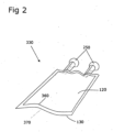
- An example of a plastic bag 330 is shown in Fig. 2 .
- Further figures show individual components and/or process sequences of the device or the manufacturing process in more detail.
- Two layers of a plastic film 120, 130 are provided by a film dispenser 340.
- the plastic films 120, 130 are unwound from a drum 342.
- a three-layer polypropylene film, for example, can serve as the plastic film 120, 130.
- a three-layer polypropylene film can be made from polypropylene and copolymers. Such a three-layer polypropylene film can be coextruded with an outer protective layer, a middle barrier layer, and an inner sealing layer.
- the two inner layers of the two plastic films 120, 130 lie on top of each other, and the two layers of the plastic films 120, 130 are rolled together on the drum 342.
- the plastic films 120, 130 are conveyed to a film printing unit 260.
- the film printing unit 260 information about the material of the plastic films 120, 130, the date of manufacture and ingredients for the plastic bags 330 to be produced are printed on the plastic films 120, 130.
- the two layers of plastic film 120, 130 pass from the film printing unit 260 to the combined welding/cutting tool or welding/separating tool 90.
- Plastic elements 250 which are held on a nest 180, are also introduced into the combined welding/cutting tool 90.
- nests 180 are fixed on a first belt and can be transported with the first belt.
- the advance of the nests 180 is timed to coincide with the cycle of the combined welding/cutting tool 90.
- the feed is stopped.
- a device fills the nests 180 with plastic elements 250. Filling can be done, for example, by pressing them into a recess in the nests 180. Filling occurs during the standstill phase of a welding/cutting step.
- One or more plastic elements 250 can be held in one of the nests 180.
- two plastic elements 250 can be held in the nest 180.
- the plastic elements 250 have an upper position and a lower position in which they can be held in the nest 180.
- the nests 180 themselves or parts of the nests 180 it is possible for the nests 180 themselves or parts of the nests 180 to have an upper position and a lower position.
- the plastic elements 250 are held in the upper position. In the upper position, the nests 180 can hold the plastic elements 250 over the lower tool plate 100 of the combined welding/cutting tool 90. In the lower position of the plastic elements 250 in the nest 180, the combined welding/cutting tool 90 can be closed.
- the plastic elements 250 pass through a preheating station 270 before reaching the combined welding/cutting tool.
- the plastic elements 250 are located on the nests 180.
- the plastic elements 250 can be heated for a shortened and improved welding step in the combined welding/cutting tool 90.
- the process is carried out such that, during the cutting/welding step, the plastic elements 250 that are to be attached to the next plastic bags 330 in the next cutting/welding step are located in the preheating station 270.
- the preheating station 270 is designed such that four plastic elements 250 located in two nests 180 can be heated simultaneously.
- the feed of the first belt is restarted.
- the four plastic elements 250 on the two nests 180 are inserted into the combined welding/cutting tool 90.
- the plastic elements 250 are inserted with one end region between the two layers of plastic films 120, 130.
- four plastic elements 250 are inserted into the combined welding/cutting tool 90 to form four ports on two plastic bags 330.
- the plastic films 120, 130 lie largely on a lower tool plate 100.
- the flat lower tool plate 100 is maintained at a constant temperature of approximately 100°C by heating elements. This temperature is below the softening temperature of the plastic films 120, 130. This allows the plastic films 120, 130 to slide smoothly over the lower tool plate 100 without "sticking" to it.
- the lower tool plate 100 is made of hard and/or tempered steel.
- the lower tool plate 100 is replaceable and immovably mounted on the device 350.
- inserts 380 are located in the lower tool plate 100.
- the inserts 380 have a recess to compensate for the thickness of the plastic elements 250 when the upper tool plate 110 is pressed onto the lower tool plate 100.
- the inserts 380 have a heater that can be controlled separately from the rest of the lower tool plate 100.
- an insert 380 with two recesses accommodates two plastic elements 250 for a plastic bag 330. The separately controllable heater helps weld the plastic elements 250 to the plastic film 120, 130, in particular to the lower plastic film 130.
- temperatures e.g., 140°C, above the melting temperature of the materials used for the plastic films 120, 130, can be achieved in the area of the inserts 380 of the lower tool plate 100.
- the inserts 380 in the lower tool plate 100 are replaceable and fixedly mounted on the device 350.
- the inserts 380 can be exchanged for other shapes of plastic bags 330 or replaced due to wear.
- the upper tool plate 110 of the combined welding/cutting tool 90 comprises a steel support plate on which an aluminum heating plate 115 formed with welding molds 40 and separating devices forming a cutting mold 80 are mounted.
- the separating devices are knife-like steel pieces that cut through the plastic films 120, 130 and thus cut the plastic bags 330 from the plastic films 120, 130.
- the formed aluminum heating plate 115 has a rapid temperature control with which temperatures, e.g., 140°C, above the melting point of the materials used for the plastic films 120, 130 can be set and maintained.
- the aluminum heating plate 115 has recesses in the area in which it is pressed onto the plastic elements 250 when the combined welding/cutting tool 90 is moved together.
- the separating devices forming the cutting die 80 and the shaped aluminum heating plate 115 are interchangeable. By exchanging the separating devices and the aluminum heating plate 115, different shapes of plastic bags can be produced or worn tool parts can be replaced.
- the upper tool plate 110 is connected to the device 350 with pressing devices: This allows the upper tool plate 110 to be pressed onto the immovably mounted lower tool plate 100.
- the plastic films 120, 130, preheated by the lower tool plate 100 are welded to the plastic elements 250, preheated in the preheating station 270, by the heat supplied in the inserts 380 of the lower tool plate 100 and the aluminum heating plate 115 of the upper tool plate 110, and are cut by the separating devices along the cutting die 40.
- the cutting process is only partially performed.
- the essentially cut-out plastic bags 250 are still connected to the remains of the plastic films 120, 130.
- the plastic elements 250 are pressed into the lower position when the combined welding/cutting tool 90 is moved together. In the lower position, the plastic elements are then at least partially located in the recess of the inserts 380 of the lower tool plate 100.
- the finished plastic bags 330 are then pulled out of the combined welding/cutting tool 90 onto the nests 180.
- the plastic elements 250 now attached to the plastic bag 330 are pushed back into the upper position of the nests 180, and the feed of the first belt is activated.
- the held plastic elements 250 in the example, the two plastic elements 250 connected to a plastic bag 330 are held in one nest—and thus the plastic bags 330 are pulled out of the combined welding/cutting tool 90.
- the remnants of the plastic films 120, 130, which are still at least partially connected to the plastic bags 330, are also pulled out of the combined welding/cutting tool 90.
- the finished plastic bags 330 are fed to a post-welding station 280 at the nests.
- the connection between the plastic elements 250 and the plastic bag 330 made from the plastic films 120, 130 is heated again.
- the connection area between the plastic elements 250 and the plastic bags 330 again is further sealed.
- a remover removes the remnants of the plastic films 120, 130 and tears them off the plastic bags 330.
- the removal can be performed, for example, with a third gripper.
- the third gripper grasps the remnants of the plastic films 120, 130 with gripping fingers and tears the remnants off the plastic bags 330 held at the nests 180.
- the plastic bags 330 are then pushed out of the nests 180 in a transfer station 290, pivoted from the horizontal to the vertical, and transferred to further nests 185.
- the plastic bags 330 are fed to the bag filling machine 300.
- filling devices 310 are placed on or over the ports, and a liquid 200 can be filled into the plastic bags 250.
- filling is carried out simultaneously at both ports of a plastic bag 330.
- the dosage of the amount of liquid 200 can, in one embodiment, be controlled by a timer of a dosing valve 190 (in Fig. 8 shown).
- the liquid 200 is kept at a constant pressure (between 2 and 6 bar) using a pressure equalization tank 320.
- a mass flow measurement system can be provided between the pressure equalization tank and the dosing valve.
- the mass flow measurement system measures the liquid and closes the dosing valve 190 as soon as the desired amount of liquid 200 has been filled into the bag. This mass flow measurement system can further increase the accuracy of the dosing.
- the plastic bags 330 After filling, the plastic bags 330, still at the additional nests 180, are fed to a closing station. In the closing station, the plastic bags 330 can be closed with caps. The closure with caps can be achieved by pressing on caps with seals. Alternatively, a closing station is also possible in which caps are welded onto the plastic bags 330.
- FIG. 2 A plastic bag 330 with two ports formed by plastic elements 250 is shown.
- the plastic elements 250 are sealed between two layers of plastic film 120, 130.
- Such a plastic bag 330 can typically contain volumes between 100 ml and 3000 ml.
- the inner perimeter of the plastic bag 330 is defined by the sealing of the plastic bag 330.
- the outer perimeter is defined by the cutting of the plastic bag 330.
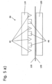
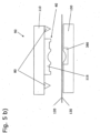
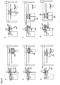
- a welding tool 10 In Fig. 3 , is a welding tool 10 and in Fig. 4 a cutting tool 50 for the device 350 for producing plastic bags 330 is shown.
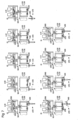
- a cutting tool 50 for the device 350 for producing plastic bags 330 In Fig. 5 a) and b) A combined welding/cutting tool 90 for an apparatus 350 for producing plastic bags 330 is shown. All three tools 10, 50, 90 each have a lower stationary platen (the lower welding tool platen 20, the lower cutting tool platen 60, and the lower tool platen 100) and a movable upper platen (the upper welding tool platen 30, the upper cutting tool platen 70, and the upper tool platen 110) that can be pressed onto the lower stationary platen. Preferred embodiments of the preferred combined welding/cutting tool 90 are described below.
- the lower tool plate 100 of the combined welding/cutting tool 90 is made of hardened steel and is mounted stationary on the device 350.
- the lower tool plate is approximately 500 mm wide and 500 mm long, with a thickness of approximately 10 mm.
- the lower tool plate 100 is equipped with a heating device, e.g., electric heating coils, as well as one or more near-surface temperature sensors. The data from the temperature sensors can be used to regulate the heating and thus the temperature of the lower tool plate 100.
- the temperature of the lower tool plate 100 is set to a constant value.
- the lower tool plate 100 includes its insert 380 in an area in which plastic elements 250 are to be welded to the plastic bags 330.
- This Insert 380 may be made of a different material than the lower tool plate 100, e.g., aluminum.
- the insert 380 may be equipped with a heating, temperature sensing, and temperature control system separate from the heating of the lower tool plate 90.
- the insert 380 in Fig. 5 b) has a recess adapted to the plastic element 250 to be welded. The recess is opposed by a corresponding recess in the molded upper tool plate. Due to the recesses, the combined welding/cutting tool 90 can be moved together to such an extent that the plastic films 120, 130 are pressed together, despite the presence of a plastic element 250 in between.
- the shaped upper tool plate 110 of the combined welding/cutting tool 90 comprises Fig. 5 b) Separating devices, which are designed as a knife-like cutting die 80. These separating devices are preferably attached to the upper tool plate 110 in a detachable manner. The separating devices can be exchanged if the desired shape and/or size of plastic bags 330 is changed. The separating devices can be exchanged if they become worn, e.g., blunt.
- the upper tool plate is in Fig. 5 b) a welding mold 40 is attached.
- the welding mold 40 is preferably made of aluminum to enable high temperature control speed.
- the welding mold 40 includes a heating system, e.g., electric heating coils, and near-surface temperature sensors. Preferably, rapid temperature control for the upper tool plate 110 is possible. This allows a preset temperature to be maintained even when the upper tool plate 110 is moved toward the lower tool plate 100, resulting in heat transfer and/or changing temperature radiation conditions.
- Contours are incorporated into the welding mold 40, along which the plastic films 120, 130 are welded together.
- the welding mold 40 has a recess corresponding to the recess in the insert 380 in the lower tool plate 100.
- the welding mold 40 is preferably attached to the upper tool plate 110 in an interchangeable manner, e.g., with screw connections.
- FIG. 6 a) to d) A diagram is shown illustrating the action of a gripping system 155 to accelerate the workflow on a combined welding/cutting tool 90.
- the diagram represents a bird's-eye view of the upper tool plate 110.
- Fig. 6 a The state is shown in which the combined welding/cutting tool 90 is compressed for the welding/cutting process and the first gripper 160 and the second gripper 170 have been extended from the combined welding/cutting tool 90.
- the two layers of plastic film 120, 130 are compressed in the combined welding/cutting tool 90 and are cut and welded together.
- Fig. 6 b The first gripper 160 and the second gripper 170 are guided around the combined welding/cutting tool 90 and grip the plastic films 120, 130.
- the step of guiding them around the combined welding/cutting tool 90 occurs during the welding/cutting process. This can shorten the time until a new piece of plastic film is inserted.
- the plastic films 120, 130 are pulled into the combined welding/cutting tool 90 by the first gripper 160 and the second gripper 170.
- the lower tool plate 100 and the upper tool plate 110 include recesses for the first gripper 160 and the second gripper 170. This allows the combined welding/cutting tool 90 to be closed while the first gripper 160 and the second gripper 170 hold the plastic films 120, 130 ( Fig. 6 c) .
- the first gripper 160 and the second gripper 170 are then in Fig. 6 d) moved out of the combined welding/cutting tool 90, whereby the initial situation is restored.
- Fig. 7 Numbers 1 to 10 show the process flow of the combined welding/cutting process in detail. The individual work steps are shown from above and from the side.
- the combined welding/cutting tool 90 is shown open, with finished plastic bags 330.
- a first gripper 160 is located in front of the combined welding/cutting tool and has gripped the two layers of plastic film 120, 130.
- No. 2 shows the opened combined welding/cutting tool 90 again.
- the first gripper 160 has pulled the two layers of plastic film 120, 130 through the combined welding/cutting tool.
- the first gripper 160 is located at the end of the combined welding/cutting tool 90 and holds the two layers of plastic film 120, 130.
- No. 3 shows the now closed combined welding/cutting tool.
- the first gripper 160 still holds the plastic films 120, 130.
- the first gripper 160 is located in a recess in the combined welding/cutting tool.
- the plastic films 120, 130 are pressed together by the combined welding/cutting tool 90.
- the first gripper 160 While the welding/cutting process is now running, the first gripper 160 is opened in No. 4. In No. 5, the first gripper 160 is pulled out of the combined welding/cutting tool 90 and moved to the beginning or in front of the combined welding/cutting tool 90 in No. 6.
- the first gripper 160 is closed around the plastic films 120, 130.
- the combined welding/cutting tool 90 is opened after the welding/cutting process is completed.
- the plastic films 120, 130 can then be pulled back into the opened combined welding/cutting tool 90 after removing the finished plastic bags 330 and any remaining plastic films 120, 130.
- the illustrated first gripper 160 is preferably designed as a mechanical gripper that grips the plastic films between two fingers.
- the movement of the first gripper 160 can be pneumatic, hydraulic, or electric motor driven.
- the movement of the first gripper 160 can be along a rail.
- the second gripper 170 is similarly designed.
- the remains are removed from the combined welding/cutting tool 90 while still slightly connected to the finished plastic bags 330.
- the plastic bags 330 are then separated from the remains outside the combined welding/cutting tool 90.
- the separation of the remains and plastic bags 330 can be achieved, for example, by a third gripper (not shown). The third gripper grasps the connected remains and tears the remains from the plastic bags 330 held on the nests.
- the dosing valve 190 shown for the bag filling machine 300 comprises a valve stem 230.
- the dosing valve 190 is designed as a diaphragm valve.
- the valve stem 230 presses on a diaphragm 235.
- the dosing valve 190 is closed, the diaphragm 235 seals two line openings 240.
- the chamber 210 of the dosing valve 190 is filled with the liquid 200 to be dosed, which is added under constant pressure.
- the dosing valve 190 is opened, the liquid 200 flows through the two line openings 240 into the two supply lines 220.
- the liquid 200 flows into one supply line 220 per port.
- the diameters of the supply lines 220 are selected such that the liquid 200 can adhere to the supply line due to its surface tension. This establishes an upper diameter of approximately 5 mm. Since the supply lines must be accessible for cleaning, the minimum diameter is limited to approximately 1 mm. Typical inner diameters of the supply lines are approximately 3 mm. Larger inner diameters can be realized, but then strainers are necessary to prevent dripping. Strainers themselves are difficult to clean, must be replaced, and can contaminate the liquid with fragments of the strainer.
- a dosing valve 190 as shown in Fig. 8 has a size of approximately 60 mm in diameter with a total length of approximately 200 mm.
- the dosing valve 190 can be driven by conventional electromagnetic and/or pneumatic methods. Dosing from the dosing valve 190 occurs at constant fluid pressure over the outflow time, i.e., the period during which the dosing valve 190 is open. The required outflow time can be determined using a mass flow system.
- An advantage of the described embodiment of the dosing valve is the avoidance of potentially different switching times, unlike with two dosing valves. This prevents inaccuracies. Advantages also arise when sterilizing the device 350. With two dosing valves, an unnoticed incomplete opening of one of the two dosing valves could lead to an unnoticed incomplete sterilization of the incompletely opened valve. With the described arrangement, it is easier to ensure that the steam passage reaches all areas equally during sterilization.
- Fig. 9 Nos. 1 to 6 show the process of pivoting the plastic bags 330 from a horizontal to a vertical position with the ports of the plastic bags 330 facing upward. The rotation of the plastic bags 330 takes place before the bag filling machine. Nos. 1 to 6 each show the process in two side views.
- the plastic bags 330 are pushed from the nests 180 into a holder 400 in No. 2.
- the pivoting of the holder 400 is carried out in No. 5.
- No. 6 shows how the plastic bags 330 are pushed out of the holders 400 onto another nest 185.
- the additional nests 185 are attached to a second belt.
- the plastic bags 330 can then be brought to the bag filling machine 300.
- This method of pivoting the plastic bag 330 avoids the previous use of a dome that was pushed into the interior of the plastic element. This could cause contamination within the plastic bag 330.
Landscapes
- Engineering & Computer Science (AREA)
- Mechanical Engineering (AREA)
- Physics & Mathematics (AREA)
- Thermal Sciences (AREA)
- Making Paper Articles (AREA)
- Lining Or Joining Of Plastics Or The Like (AREA)
Description
- Die vorliegende Erfindung liegt auf dem Gebiet der Kunststoffverarbeitung und der Anlagentechnik. Die vorliegende Erfindung betrifft eine Vorrichtung und ein Verfahren zur Herstellung von Kunststoffbeuteln mit einem oder mehreren Ports bzw. Kunststoffelementen.
- Kunststoffbeutel, häufig in Form von Folienbeuteln, werden im Bereich der Medizin eingesetzt. Ihre Verwendungsmöglichkeiten sind vielfältig. Kunststoffbeutel können zur Aufnahme von Infusionslösungen dienen und werden unter anderem auch für die Aufbewahrung von Blut (Blutkonserven) und die Aufbewahrung von sterilen medizinischen Flüssigkeiten benutzt. Kunststoffbeutel benötigen Befüllungs- und Entnahmesysteme, die als sogenannte Ports ausgeführt sind, wobei die Kunststoffbeutel je nach Verwendungszweck ein, zwei oder mehrere Ports aufweisen können. Jeder Port kann, je nach vorgesehener Verwendungsart, eine spezielle Formgebung und/oder individuelle Konstruktionsbestandteile haben.
- Kunststoffbeutel mit Ports sind z. B. aus den Schriften
DE 196 34 944 C1 undDE 199 58 952 A1 bekannt. Dort werden Herstellungsverfahren beschrieben, bei denen ein einstückiges Einsatzstück aus Kunststoff in den Randbereich eines aus zwei übereinanderliegenden Kunststofffolien gebildeten Kunststoffbeutels eingeschweißt wird. Das Einsatzstück besteht aus einem massiven Stück Kunststoff von ausreichender Querschnittsgröße, sodass in dem Einsatzstück wahlweise ein, zwei oder mehrere Ports mit jeweils zylinderförmig kreisrundem Durchströmungsquerschnitt unterzubringen sind. - Ports können in Kunststoffbeuteln mit verschiedenen Arten von Kunststoffelementen realisiert werden. Kunststoffelemente können als extrudierte Schläuche, z.B. aus Polypropylen mit oder ohne eine innere Schicht aus EVA, ausgebildet sein. Kunststoffelemente können auch als Spritzgussteile, z.B. aus Polypropylen, ausgebildet sein.
- Die Herstellung von Kunststoffbeuteln erfolgt in bekannter Weise mit einem Herstellungsverfahren, bei dem zwei miteinander zu verschweißende Kunststofffolien einem Schweiß/Schneidwerkzeug zugeführt werden, das ein- oder mehrnutzig sein kann, d.h. dessen Werkzeugform für ein oder mehrere Kunststoffbeutel ausgelegt sein kann. Die Zuführung der miteinander zu verschweißenden Kunststoff-Folien erfolgt in Form von planparallel übereinanderliegenden Endlos-Kunststofffolien, die üblicherweise als geblasener Endlos-Schlauch ungeschnitten oder in Bahnen geschnitten von einer Rolle abgezogen und mittels Tänzerwalzen gestreckt gehalten werden, wobei durch bekannte Mittel (z. B. durch eine Folienklemme) sichergestellt ist, dass das Zuführungsende der Kunststofffolien lagegenau an der Eingangsseite des aus zwei Werkzeughälften gebildeten Schweiß-/Schneidwerkzeuges positioniert ist.
- Sodann werden die Werkzeughälften auseinander gefahren und die Kunststofffolien werden durch das geöffnete Werkzeug hindurchgezogen Zu diesem Zweck greifen üblicherweise Vakuumsauger durch das geöffnete Werkzeug hindurch und erfassen das an der Eingangsseite des Werkzeuges lagegenau positionierte Zuführungsende der Kunststofffolien und ziehen dieses Zuführungsende bis auf die Ausgangsseite durch das geöffnete Werkzeug hindurch, woraufhin beim oder kurz nach dem Zufahren (Schließen) der Werkzeughälften die Schweißnähte zwischen den Kunststofffolien konturengenau entsprechend der Form des oder der Kunststoffbeutel hergestellt werden und zugleich mittels Trennmesser, die in das Schweiß-/Schneidwerkzeug eingebaut sind, die Kunststoffbeutel freigeschnitten und von den noch frischen (unverschweißten) Kunststofffolien abgetrennt werden, derart, dass ein neues Zuführungsende der Kunststofffolien an der Eingangsseite des Schweiß-/Schneidwerkzeuges positioniert ist.
- Aus der Offenlegungsschrift
DE 1 486 977 ist eine Maschine zum Herstellen von Verpackungsbeuteln für Verpackungsgüter mit runden Ecken bekannt. Die Maschine verfügt über eine Schneid- und Schweißvorrichtung, welche Abschnitte der Folie abschneidet und gleichzeitig die Schnittkanten zuschweißt, um abgerundete Ecken an den Beuteln zu erzielen. Dabei werden die einzelnen Beutel nicht voneinander getrennt, sondern die zusammenhängende Folie wird nach dem Schweißen über Bänder und Walzen geführt, bevor sie an einer separaten Trennstation in einzelne Beutel zertrennt wird. - Aus der
FR 2 627 128 - Aus der
US 3,244,576 ist eine Vorrichtung und ein Verfahren zur Herstellung von flexiblen Beuteln bekannt. Die Beutel sind mit einem starren oder halbstarren Mundstück bzw. Stutzen versehen. Bei dem offenbarten Verfahren wird eine erste Materialbahn aus heißversiegelbarem Material (heißversiegelbarer Film) über eine waagrechte Platte bewegt. Danach wird an einer bestimmten Stelle an der Platte auf einem Abschnitt der ersten Materialbahn ein heißversiegelbares Mundstück bzw. Stutzen aufgebracht und gleichzeitig mit dem Abschnitt versiegelt, während, in Ausrichtung mit dem Mundstück, eine Öffnung mittels eines (Durch-)Schneidvorgangs (Durchstoßen) in dem Abschnitt gebildet wird. Nach einer weiteren Vorwärtsbewegung der ersten Materialbahn mit dem nun darauf angebrachten Mundstück wird anschließend eine zweite Materialbahn aus heißversiegelbarem Material in flächiger Berührung über die erste Materialbahn gelegt und entsprechend überlagerte Abschnitte entlang ihrer Randkanten verbunden, um den Beutel zu bilden. Der verbleibende Teil der Streifen wird danach abgetrennt. Die Vorrichtung zur Durchführung des Verfahrens weist eine, mit einer abgeschrägten Öffnung versehene, Platte sowie Walzen zum Vorwärtsbewegen der ersten Materialbahn über eine Fläche der Platte auf. Des Weiteren ist ein drehbares Schaltrad mit Aufnahmeeinheiten für Mundstücke zum Aufbringen der heißversiegelbaren Mundstücke auf die erste Materialbahn vorgesehen, welche der Öffnung der Platte gegenüberliegt und sich nahe der Oberfläche der Platte befindet. An der gegenüberliegenden Seite, d.h. an der Unterseite der Platte befindet sich, in Ausrichtung mit deren Öffnung und der Einrichtung zum Aufbringen des Mundstücks, ein ringförmiges, zylindrisches Heißversiegelungswerkzeug mit Heizelementen und Schneidelementen. Die Schneidelemente sind schräge Klingen in radialer Anordnung, um die erforderliche Öffnung zwischen dem Mundstück und dem Inneren des fertigen Beutels zu schaffen. Das Heißversiegelungswerkzeug wird durch einen pneumatischen Zylinder hin- und herbewegt. Daneben verfügt die Vorrichtung noch über eine weitere separate Schweiß- und Trennstation mit Walzen und einem Förderriemen zum Zuführen und Transportieren der zweiten Materialbahn an heißversiegelbarem Material und über eine Platte, um darauf die flexible erste Materialbahn mit dem Mundstück in Flächenberührung (an der dem Mundstück gegenüberliegenden Unter-, d.h. Innenseite) mit der zweiten Materialbahn auf der Platte zu bringen. Des Weiteren ist ein mit Heißversiegelungselementen versehenes Werkzeug, welches in senkrechter Richtung zu den überlagerten Materialbahnen bewegt werden kann, vorgesehen. Das Werkzeug ist gegen die auf der Platte befindlichen, übereinander liegenden Materialbahnen bewegbar, damit die Umfangsränder des Beutels durch das Werkzeug miteinander versiegelt werden können. Weiterhin kann dieses Werkzeug den fertig entstandenen Beutel nach dem Versiegelungsvorgang von den Materialbahnen abtrennen. - Die beschriebenen Herstellungsverfahren sind hinsichtlich der Details der Verfahrensabläufe und der dafür verwendeten Anlagen und Vorrichtungen vielfach optimiert worden. Jedoch ist es bisher nicht gelungen, eine wesentliche Leistungssteigerung bei der Kunststoffbeutelherstellung zu erreichen. Die zeitlichen Abläufe der einzelnen Verfahrensschritte des Schweißens und des Schneidens sowie ein positionsgenaues Handling der fertigen Kunststoffbeutel und ggf. deren Befüllung und Versiegelung sowie gewünschtenfalls deren Einbringung in einen Umbeutel erschienen nicht veränderbar.
- Aufgabe der Erfindung ist es, eine verbesserte Herstellung von Kunststoffbeuteln durch neue oder verbesserte Verfahrensschritte und neue oder verbesserte Vorrichtungen zu erreichen.
- Diese und weitere Aufgaben werden durch eine Vorrichtung mit den Merkmalen des Anspruches 1 und ein Verfahren mit den Merkmalen des Anspruches 19 gelöst, bevorzugte Ausgestaltungen sind in den jeweiligen abhängigen Ansprüchen definiert.
-
-
Fig. 1 zeigt eine Skizze einer Ausführungsform einer Vorrichtung zur Herstellung von Kunststoffbeuteln; -
Fig. 2 zeigt schematisch einen Kunststoffbeutel mit Port; -
Fig. 3 zeigt schematisch ein Schweißwerkzeug; -
Fig. 4 zeigt schematisch ein Schneidwerkzeug; -
Fig. 5 a) undb) zeigen schematisch ein kombiniertes Schweiß-/Schneidwerkzeug; -
Fig. 6 a) bis d) zeigen schematisch den Verfahrensablauf beim Umfahren eines kombinierten Schweiß-/Schneidwerkzeugs durch einen ersten Greifer und einen zweiten Greifer; -
Fig. 7 , Nr. 1 bis 10, zeigt detailliert einen Fertigungsablauf an einem kombinierten Schweiß-/Schneidwerkzeug; -
Fig. 8 zeigt schematisch ein Dosierventil zur Befüllung von Kunststoffbeuteln; -
Fig. 9 zeigt detailliert den Fertigungsablauf des Schwenkens der Kunststoffbeutel aus der Horizontalen in die Vertikale Lage nach dem Schweiß-/Trennvorgang. -
Fig. 1 zeigt beispielhaft eine Vorrichtung 350 zur Herstellung von Kunststoffbeuteln 330 sowie das damit verbundene Herstellungsverfahren. Ein Beispiel eines Kunststoffbeutels 330 ist inFig. 2 dargestellt. Weitere Figuren zeigen detaillierter einzelne Bestandteile und/oder Verfahrensabläufe der Vorrichtung bzw. des Herstellungsverfahrens. Zwei Lagen einer Kunststofffolie 120, 130 werden von einem Folienspender 340 zur Verfügung gestellt. Die Kunststofffolien 120, 130 werden dabei von einer Trommel 342 abgerollt. Als Kunststofffolie 120, 130 kann z.B. eine dreischichtige Polypropylenfolie dienen. - Eine dreischichtige Polypropylenfolie kann aus Polypropylen und Kopolymeren gefertigt sein. Eine derartige dreischichtige Polypropylenfolie kann mit einer äußeren Schutzschicht, einer mittleren Barrierenschicht und einer inneren Schicht zum Verschweißen koextrudiert werden. In der Vorrichtung 350 liegen die beiden inneren Schichten der beiden Kunststofffolien 120, 130 aufeinander und die zwei Lagen der Kunststofffolien 120, 130 sind zusammen auf der Trommel 342 aufgerollt.
- Vom Folienspender 340 gelangen die Kunststofffolien 120, 130 zu einer Folienbedruckeinheit 260. in der Folienbedruckeinheit 260 werden auf die Kunststofffolien 120, 130 Informationen über das Material der Kunststofffolien 120, 130, das Herstellungsdatum und Inhaltstoffe für die zu fertigenden Kunststoffbeutel 330 aufgedruckt.
- Die zwei Lagen Kunststofffolie 120, 130 gelangen von der Folienbedruckeinheit 260 zum kombinierten Schweiß/Schneidwerkzeug bzw. Schweiß-/Trennwerkzeug 90. Ebenfalls in das kombinierte Schweiß/Schneidwerkzeug 90 werden Kunststoffelemente 250, die auf einem Nest 180 gehalten werden, eingebracht.
- Mehrere der Nester 180 befinden sich fix auf einem Ersten Riemen und können mit dem Ersten Riemen befördert werden. Der Vorschub der Nester 180 ist zeitlich mit dem Takt des kombinierten Schweiß/ Schneidwerkzeugs 90 koordiniert. Während des Schweiß/Schneidschritts steht der Vorschub still. Eine Vorrichtung befüllt die Nester 180 mit Kunststoffelementen 250. Die Befüllung kann z.B. durch Hineindrücken in eine Passung in den Nestern 180 geschehen. Das Befüllen geschieht in der Stillstandsphase während eines Schweiß/Schneidschritts.
- In einem der Nester 180 können eines oder mehrere Kunststoffelemente 250 gehalten werden. Im dargestellten Fall können zwei Kunststoffelemente 250 in dem Nest 180 gehalten werden. Die Kunststoffelemente 250 haben eine obere Position und eine untere Position, in der sie im Nest 180 gehalten werden können. Alternativ besteht die Möglichkeit, dass die Nester 180 selber oder Teile der Nester 180 eine obere Position und eine untere Position haben. Im Beispiel werden die Kunststoffelemente 250 in der oberen Position gehalten. In der oberen Position können die Nester 180 die Kunststoffelemente 250 über die untere Werkzeugplatte 100 des kombinierten Schweiß/Schneidwerkzeugs 90 führen. In der unteren Position der Kunststoffelemente 250 im Nest 180 kann das kombinierte Schweiß/Schneidwerkzeug 90 geschlossen werden.
- Die Kunststoffelemente 250 durchlaufen vor dem kombinierten Schweiß/Schneidwerkzeug eine Vorwärmstation 270. Die Kunststoffelemente 250 befinden sich dabei auf den Nestern 180. In der Vorwärmstation 270 können die Kunststoffelemente 250 für einen verkürzten und verbesserten Schweißschritt im kombinierten Schweiß/Schneidwerkzeug 90 erwärmt werden. Das Verfahren wird so durchgeführt, dass sich während des Schneid/Schweißschritts die Kunststoffelemente 250, die an den nächsten Kunststoffbeuteln 330 im nächsten Schneid/Schweißschritt angebracht werden sollen in der Vorwärmstation 270 befinden. Die Vorwärmstation 270 ist so aufgebaut, dass vier Kunststoffelemente 250, die sich in zwei Nestern 180 befinden gleichzeitig erwärmt werden können.
- Nach oder beim Öffnen des kombinierten Schweiß/Schneidwerkzeugs 90 wird der Vorschub des ersten Riemens wieder in Gang gesetzt. Die vier Kunststoffelemente 250 auf den zwei Nestern 180 werden in das kombinierte Schweiß/Schneidwerkzeug 90 eingebracht.
- Im kombinierten Schweiß/Schneidwerkzeug 90 werden die Kunststoffelemente 250 mit einem Endbereich zwischen die zwei Lagen der Kunststofffolien 120, 130 einbebracht. In der dargestellten Ausführungsform der Erfindung werden vier Kunststoffelemente 250 zur Formung von vier Ports an zwei Kunststoffbeuteln 330 in das kombinierte Schweiß/Schneidwerkzeug 90 eingebracht. Die Kunststofffolien 120, 130 liegen weitgehend auf einer unteren Werkzeugplatte 100. Die ebene untere Werkzeugplatte 100 wird mit Heizelementen auf einer konstanten Temperatur von ungefähr 100 °C gehalten. Diese Temperatur liegt unterhalb der Erweichungstemperatur der Kunststofffolien 120, 130. Dadurch können die Kunststofffolien 120, 130 problemlos über die untere Werkzeugplatte 100 gleiten, ohne darauf "anzukleben". Die untere Werkzeugplatte 100 ist aus hartem und/oder gehärtetem Stahl gefertigt. Die untere Werkzeugplatte 100 ist auswechselbar und unbeweglich an der Vorrichtung 350 montiert.
- In den Bereichen der unteren Werkzeugplatte 100, in denen die Kunststoffelemente 250 auf der unteren Kunststofffolie 130 aufliegen, befinden sich Einsätze 380 in der unteren Werkzeugplatte 100. Die Einsätze 380 haben eine Vertiefung, um beim Pressen der oberen Werkzeugplatte 110 auf die untere Werkzeugplatte 100 die Dicke der Kunststoffelemente 250 auszugleichen. Die Einsätze 380 haben eine von der restlichen unteren Werkzeugplatte 100 separat regelbare Heizung. In einer bevorzugten Ausführungsform nimmt ein Einsatz 380 mit zwei Vertiefungen 2 Kunststoffelemente 250 für einen Kunststoffbeutel 330 auf. Die separat regelbare Heizung hilft die Kunststoffelemente 250 an die Kunststofffolie 120,130, insbesondere an die untere Kunststofffolie 130, anzuschweißen. Mit der separat regelbaren Heizung können im Bereich der Einsätze 380 der unteren Werkzeugplatte 100 Temperaturen, z.B. 140 °C, oberhalb der Schmelztemperatur der verwendeten Materialien für die Kunststofffolien 120, 130 erzielt werden. Die Einsätze 380 in der unteren Werkzeugplatte 100 sind auswechselbar und unbeweglich an der Vorrichtung 350 montiert. Die Einsätze 380 können für andere Formen von Kunststoffbeuteln 330 ausgetauscht werden oder wegen Verschleiß ersetzt werden.
- Die obere Werkzeugplatte 110 des kombinierten Schweiß/Schneidwerkzeugs 90 umfasst eine Stahlträgerplatte, auf der eine mit Schweißformen 40 geformte Aluminiumheizplatte 115 und Trennvorrichtungen, die eine Schneidform 80 bilden, montiert sind. Als Trennvorrichtungen dienen messerartige Stahlstücke, die die Kunststofffolien 120, 130 durchschneiden und so die Kunststoffbeutel 330 aus den Kunststofffolien 120, 130 ausschneiden. Die geformte Aluminiumheizplatte 115 hat eine schnelle Temperaturregelung, mit der Temperaturen, z.B. 140 °C, oberhalb des Schmelzpunktes der verwendeten Materialien der Kunststofffolien 120, 130 eingestellt und gehalten werden können. Die Aluminiumheizplatte 115 hat, wie die untere Werkzeugplatte 100, Vertiefungen in dem Bereich in dem sie beim Zusammenfahren des kombinierten Schweiß/Schneidwerkzeugs 90 auf die Kunststoffelemente 250 gedrückt wird. Die Trennvorrichtungen, welche die Schneidform 80 bilden, sowie die geformte Aluminiumheizplatte 115 können ausgewechselt werden. Durch Auswechseln der Trennvorrichtungen und der Aluminiumheizplatte 115 können unterschiedliche Formen von Kunststoffbeuteln hergestellt werden oder verschlissene Werkzeugteile ersetzt werden.
- Die obere Werkzeugplatte 110 ist an der Vorrichtung 350 mit Pressvorrichtungen verbunden: Dadurch kann die obere Werkzeugplatte 110 auf die unbeweglich montierte untere Werkzeugplatte 100 gedrückt werden.
- Beim Zusammendrücken werden die, durch die untere Werkzeugplatte 100 vorgewärmten, Kunststofffolien 120, 130 mit den in der Vorwärmstation 270 vorgewärmten Kunststoffelementen 250 durch die Wärmezufuhr in den Einsätzen 380 der unteren Werkzeugplatte 100 und der Aluminiumheizplatte 115 der oberen Werkzeugplatte 110 verschweißt und durch die Trennvorrichtungen entlang der Schneidform 40 geschnitten. Bei dieser Ausführungsform wird der Schneidvorgang nur teilweise durchgeführt. Die im Wesentlichen ausgeschnittenen Kunststoffbeutel 250 hängen noch mit den Überresten der Kunststofffolien 120, 130 zusammen. Die Kunststoffelemente 250 werden beim Zusammenfahren des kombinierten Schweiß/Schneidwerkzeugs 90 in die untere Position gedrückt. In der unteren Position befinden sich die Kunststoffelemente dann zumindest teilweise in der Vertiefung der Einsätze 380 der unteren Werkzeugplatte 100.
- Die gefertigten Kunststoffbeutel 330 werden anschließend aus dem kombinierte Schweiß/Schneidwerkzeug 90 auf den Nestern 180 herausgezogen. Dazu werden die nun am Kunststoffbeutel 330 angebrachten Kunststoffelemente 250 wieder in die obere Position der Nester 180 gedrückt und der Vorschub des ersten Riemens wird betätigt. Zusammen mit den Nestern 180 werden die gehalterten Kunststoffelemente 250, wobei im Beispiel die zwei Kunststoffelemente 250, die mit einem Kunststoffbeutel 330 verbunden sind in einem Nest gehalten werden, und damit die Kunststoffbeutel 330 aus dem kombinierten Schweiß/Schneidwerkzeug 90 herausgezogen. Die Überreste der Kunststofffolien 120, 130, die noch mit den Kunststoffbeuteln 330 zumindest teilweise zusammenhängen, werden dabei ebenfalls aus dem kombinierten Schweiß/Schneidwerkzeug 90 herausgezogen.
- Die gefertigten Kunststoffbeutel 330 werden an den Nestern einer Nachschweißstation 280 zugeführt. In der Nachschweißstation 280 wird die Verbindung der Kunststoffelemente 250 mit dem aus den Kunststofffolien 120, 130 gefertigten Kunststoffbeutel 330 nochmals erwärmt. Durch das nochmalige Erwärmen des Verbindungsbereichs der Kunststoffelemente 250 mit den Kunststoffbeuteln 330 wird der Verbindungsbereich weiter abgedichtet.
- Während die Kunststoffbeutel 330 an den Nestern 180 gehalten werden, entfernt ein Entferner die Überreste der Kunststofffolien 120, 130 und reißt diese von den Kunststoffbeuteln 330 ab. Das Entfernen kann z.B. mit einem dritten Greifer geschehen. Während der Stillstandspause eines Schweiß/Schneidschritts (d.h. der erste Riemen und damit die Nester 180 werden nicht bewegt) ergreift der dritte Greifer mit Greiffingem die Überreste der Kunststofffolien 120, 130 und reißt die Überreste von den an den Nestern 180 gehalterten Kunststoffbeuteln 330 ab.
- In der beschriebenen Ausführungsform der Erfindung werden die Kunststoffbeutel 330 dann in einer Transferstation 290 aus den Nestern 180 herausgeschoben, aus der Horizontalen in die Vertikale geschwenkt und an weitere Nestern 185 übergeben. In den weiteren Nestern 185, die sich auf einem zweiten Riemen befinden, werden die Kunststoffbeutel 330 der Beutelfüllmaschine 300 zugeführt.
- In der Befüllmaschine 300 werden Befüllvorrichtungen 310 auf oder über die Ports gesetzt und eine Flüssigkeit 200 kann in die Kunststoffbeutel 250 eingefülltwerden. In der beschriebenen Ausführungsform wird das Befüllen an beiden Ports eines Kunststoffbeutels 330 gleichzeitig vorgenommen. Die Dosierung der Menge der Flüssigkeit 200 kann in einer Ausführungsform über eine Zeitsteuerung eines Dosierventils 190 (in
Fig. 8 dargestellt) geschehen. Damit in gleichen Zeiträumen gleiche Mengen der Flüssigkeit 200 eingefüllt werden können, wird die Flüssigkeit 200 mit einem Druckausgleichsbehälter 320 auf konstantem Druck (zwischen 2 und 6 bar) gehalten. Alternativ zur Zeitsteuerung kann zwischen Druckausgleichstank und Dosierventil ein Massedurchflussmesssystem vorhanden sein. Das Massedurchflussmesssystem misst die Flüssigkeit und schließt das Dosierventil 190, sobald die gewünschte Menge der Flüssigkeit 200 in den Beutel eingefüllt ist. Mit diesem Massendurchflussmesssystem kann die Genauigkeit der Dosierung noch erhöht werden. Nach der Befüllung werden die Kunststoffbeutel 330, immer noch an den weiteren Nestern 180, einer Verschlussstation zugeführt. In der Verschlussstation können die Kunststoffbeutel 330 mit Kappen verschlossen werden. Der Verschluss mit Kappen kann durch Aufdrücken von Kappen mit Dichtungen vorgenommen werden. Alternativ ist auch eine Verschlussstation möglich, bei der Kappen auf die Kunststoffbeutel 330 aufgeschweißt werden. - In
Fig. 2 ist ein Kunststoffbeutel 330 mit zwei durch Kunststoffelemente 250 gebildeten Ports dargestellt. Die Kunststoffelemente 250 sind zwischen zwei Lagen Kunststofffolie, 120, 130 eingeschweißt. Ein solcher Kunststoffbeutel 330 kann Volumina zwischen typischerweise 100 ml und 3000 ml umfassen. Die innere Umrandung des Kunststoffbeutels 330 ist durch die Verschweißung des Kunststoffbeutels 330 definiert. Die äußere Umrandung ist durch das Schneiden des Kunststoffbeutels 330 definiert. - In
Fig. 3 , ist ein Schweißwerkzeug 10 und inFig. 4 ist ein Schneidwerkzeug 50 für die Vorrichtung 350 zur Herstellung von Kunststoffbeuteln 330 dargestellt. InFig. 5 a) undb) ist ein kombiniertes Schweiß/Schneidwerkzeug 90 für eine Vorrichtung 350 zur Herstellung von Kunststoffbeuteln 330 dargestellt. Alle drei Werkzeuge 10, 50, 90 haben jeweils eine untere ruhende Platte (die untere Schweißwerkzeugplatte 20, die untere Schneidwerkzeugplatte 60 und die untere Werkzeugplatte 100) sowie eine bewegbare, auf die untere ruhende Platte aufpressbare obere Platte (die obere Schweißwerkzeugplatte 30, die obere Schneidwerkzeugplatte 70 und die obere Werkzeugplatte 110). Im Folgenden werden bevorzugte Ausführungsformen des bevorzugten kombinierten Schweiß/Schneidwerkzeugs 90 beschrieben. - Die untere Werkzeugplatte 100 des kombinierten Schweiß/Schneidwerkzeugs 90 ist als ruhend an der Vorrichtung 350 angebrachte Platte aus gehärtetem Stahl gefertigt. Die untere Werkzeugplatte ist ungefähr 500 mm breit und 500 mm lang bei einer Dicke von ungefähr 10 mm. Die untere Werkzeugplatte 100 ist mit einer Heizvorrichtung, z.B. elektrische Heizschlangen ausgestattet sowie mit einem oder mehreren oberflächennahen Temperaturfühlern ausgestattet. Mit den Daten der Temperaturfühler kann die Heizung und somit die Temperatur der unteren Werkzeugplatte 100 geregelt werden. Bevorzugterweise wird die Temperatur der unteren Werkzeugplatte 100 auf einen konstanten Wert eingestellt. In einer bevorzugten Ausführungsform umfasst die untere Werkzeugplatte 100 seinen Einsatz 380 in einem Bereich, in dem Kunststoffelemente 250 an die Kunststoffbeutel 330 angeschweißt werden sollen. Dieser Einsatz 380 kann aus einem anderen Material wie die untere Werkzeugplatte 100 gefertigt sein, z.B. aus Aluminium. Der Einsatz 380 kann mit einer von der Heizung der unteren Werkzeugplatte 90 getrennten Heizung, Temperaturerfassung und Temperaturregelung ausgestattet sein. Der Einsatz 380 in
Fig. 5 b) hat eine an das einzuschweißende Kunststoffelement 250 angepasste Vertiefung. Der Vertiefung steht eine entsprechende Vertiefung in der geformten oberen Werkzeugplatte gegenüber. Durch die Vertiefungen kann das kombinierte Schweiß/Schneidwerkzeug 90, trotz eines zwischenliegenden Anteils eines Kunststoffelements 250, so weit zusammengefahren werden, dass die Kunststofffolien 120, 130 zusammengedrückt werden. - Die geformte obere Werkzeugplatte 110 des kombinierten Schweiß/Schneidwerkzeugs 90 umfasst in
Fig. 5 b) Trennvorrichtungen, die messerartig als Schneidform 80 ausgebildet sind. Diese Trennvorrichtungen sind bevorzugterweise abschraubbar an der oberen Werkzeugplatte 110 angebracht. Die Trennvorrichtungen können bei gewünschten geänderten Formen und/oder Größen von Kunststoffbeuteln 330 ausgetauscht werden. Die Trennvorrichtungen können bei Verschleiß, z.B. Abstumpfen ausgetauscht werden. Auf die obere Werkzeugplatte ist inFig. 5 b) eine Schweißform 40 angebracht. Die Schweißform 40 ist bevorzugt aus Aluminium gefertigt, um eine hohe Temperaturregelgeschwindigkeit zu ermöglichen. Die Schweißform 40 umfasst ein Heizsystem, z.B. elektrische Heizschlangen, und oberflächennahe Temperaturfühler. Bevorzugterweise ist eine schnelle Temperaturregelung für die obere Werkzeugplatte 110 möglich. Dadurch kann eine voreingestellte Temperatur auch beim Zusammenfahren der oberen Werkzeugplatte 110 auf die untere Werkzeugplatte 100 und dem dadurch entstehenden Wärmeübergang bzw. den geänderten Temperaturabstrahlverhältnissen gehalten werden. - In die Schweißform 40 sind Konturen eingearbeitet, entlang derer die Kunststofffolien 120, 130 zusammengeschweißt werden. Die Schweißform 40 hat eine zu der Vertiefung in dem Einsatz 380 in der unteren Werkzeugplatte 100 korrespondierende Vertiefung. Die Schweißform 40 ist bevorzugterweise auswechselbar, z.B. mit Schraubverbindungen, an der oberen Werkzeugplatte 110 angebracht.
- In
Fig. 6 a) bis d) ist ein Schema abgebildet, das die Wirkung eines Greifsystems 155 zur Beschleunigung des Arbeitsablaufs an einem kombinierten Schweiß/Schneidwerkzeug 90 veranschaulicht. Das Schema stellt eine Sicht aus Vogelperspektive auf die obere Werkzeugplatte 110 dar. - In
Fig. 6 a) ist der Zustand abgebildet, bei dem das kombinierte Schweiß/Schneidwerkzeug 90 für den Schweiß/Schneidvorgang zusammengedrückt ist und der erste Greifer 160 und der zweite Greifer 170 aus dem kombinierten Schweiß/Schneidwerkzeug 90 herausgefahren sind. Die zwei Lagen Kunststofffolie 120, 130 liegen zusammengedrückt im kombinierten Schweiß/ Schneidwerkzeug 90 und werden geschnitten und zusammengeschweißt. - In
Fig. 6 b) ist der erste Greifer 160 und der zweite Greifer 170 um das kombinierte Schweiß/ Schneidwerkzeug 90 herumgeführt und greifen die Kunststofffolien 120, 130. Der Schritt des Herumführens um das kombinierte Schweiß/Schneidwerkzeug 90 geschieht noch während des Schweiß/Schneidvorgangs. Dadurch kann die Zeit bis zum erneuten Einlegen eines Kunststofffolienstücks verkürzt werden. - Nach Öffnen des kombinierten Schweiß/ Schneidwerkzeug 90, und Entnahme der geschnittenen und verschweißten Kunststoffbeutel, werden die Kunststofffolien 120, 130 von dem ersten Greifer 160 und dem zweiten Greifer 170 in das kombinierte Schweiß/ Schneidwerkzeug 90 hineingezogen. Die untere Werkzeugplatte 100 und die obere Werkzeugplatte 110 umfassen Aussparungen für den ersten Greifer 160 und den zweiten Greifer 170. Dadurch kann das kombinierte Schweiß/Schneidwerkzeug 90 geschlossen werden, während der erste Greifer 160 und der zweite Greifer 170 die Kunststofffolien 120, 130 haltern (
Fig. 6 c) . - Der erste Greifer 160 und der zweite Greifer 170 sind dann in
Fig. 6 d) aus dem kombinierten Schweiß/ Schneidwerkzeug 90 herausgefahren, wodurch sich wieder die Ausgangssituation einstellt. -
Fig. 7 Nr. 1 bis 10 zeigt detailliert den Verfahrensablauf beim kombinierten Schweiß/Schneidvorgang. Die einzelnen Arbeitsschritte werden jeweils von oben und von der Seite dargestellt. - In Nr. 1 ist das kombinierte Schweiß/Schneidwerkzeug 90 geöffnet, mit gefertigten Kunststoffbeuteln 330 gezeigt. Ein erster Greifer 160 befindet sich vor dem kombinierten Schweiß/Schneidwerkzeug und hat die zwei Lagen Kunststofffolie 120, 130 ergriffen.
- In Nr. 2 ist nochmals das geöffnete kombinierte Schweiß/Schneidwerkzeug 90 dargestellt. Der erste Greifer 160 hat die zwei Lagen Kunststofffolie 120, 130 durch das kombinierte Schweiß/Schneidwerkzeug hindurchgezogen. Der erste Greifer 160 befindet sich am Ende des kombinierten Schweiß/Schneidwerkzeugs 90 und hält die zwei Lagen Kunststofffolie 120, 130 fest.
- Nr. 3 zeigt das nun geschlossene kombinierte Schweiß/Schneidwerkzeug. Der erste Greifer 160 hält die Kunststofffolien 120, 130 nach wie vor fest. Der erste Greifer 160 befindet sich in einer Aussparung im kombinierten Schweiß/Schneidwerkzeug. Die Kunststofffolien 120, 130 werden durch das kombinierte Schweiß/ Schneidwerkzeug 90 zusammengedrückt.
- Während der Schweiß/Schneidvorgang nun abläuft, wird der erste Greifer 160 in Nr. 4 geöffnet. In Nr. 5 wird der erste Greifer 160 aus dem kombinierten Schweiß/Schneidwerkzeug 90 herausgezogen und in Nr. 6 an den Anfang bzw. vor das kombinierte Schweiß/ Schneidwerkzeug 90 bewegt.
- In Nr. 7 wird gezeigt, wie der nach wie vor geöffnete erste Greifer 160 wieder in Richtung des kombinierten Schweiß/Schneidwerkzeugs 90 hinfährt und die Kunststofffolien 120, 130 umgreift.
- In Nr. 8 wird der erste Greifer 160 um die Kunststofffolien 120, 130 geschlossen.
- In Nr. 9 wird das kombinierte Schweiß/Schneidwerkzeug 90 nach abgeschlossenem Schweiß/Schneidvorgang geöffnet. Die Kunststofffolien 120, 130 können dann nach Entnahme der gefertigten Kunststoffbeutel 330 sowie eventueller Überresten von Kunststofffolien 120, 130 wieder in das geöffnete kombinierte Schweiß/ Schneidwerkzeug 90 hineingezogen werden.
- Der dargestellte erste Greifer 160 ist bevorzugterweise als mechanischer Greifer ausgebildet, der die Kunststofffolien zwischen zwei Fingern ergreift.
- Die Bewegung des ersten Greifers 160 kann pneumatisch, hydraulisch oder mit Elektromotoren erfolgen. Die Bewegung des ersten Greifers 160 kann entlang einer Schiene erfolgen. Der zweite Greifer 170 ist ähnlich ausgebildet.
- Bevorzugterweise werden die Überreste noch leicht zusammenhängend mit den gefertigten Kunststoffbeuteln 330 aus dem kombinierten Schweiß/Schneidwerkzeug 90 entnommen. Die Kunststoffbeuteln 330 werden dann außerhalb des kombinierten Schweiß/ Schneidwerkzeugs 90 von den Überresten getrennt. Die Trennung von Überresten und Kunststoffbeuteln 330 kann z.B. durch einen nichtdargestellten dritten Greifer geschehen. Der dritte Greifer ergreift die zusammenhängenden Überreste und reißt die Überreste von den auf den Nestern gehalterten Kunststoffbeuteln 330 ab.
- Das in
Fig. 8 abgebildete Dosierventil 190 für die Beutelfüllmaschine 300 umfasst einen Ventilstempel 230. Das Dosierventil 190 ist als Membranventil ausgebildet. Der Ventilstempel 230 drückt auf eine Membran 235. Die Membran 235 dichtet im geschlossenen Zustand des Dosierventils 190 zwei Leitungsöffnungen 240 ab. Der Raum 210 des Dosierventils 190 ist mit der zu dosierenden Flüssigkeit 200 gefüllt, die unter konstantem Druck zugegeben wird. Beim Öffnen des Dosierventils 190 strömt die Flüssigkeit 200 durch die beiden Leitungsöffnungen 240 in die beiden Zuleitungen 220. Die Flüssigkeit 200 strömt jeweils in eine Zuleitung 220 pro Port. Um das Abtropfen von Zuleitungen 220 zu vermeiden werden die Durchmesser der Zuleitungen 220 so gewählt, dass die Flüssigkeit 200 auf Grund ihrer Oberflächenspannung an der Zuleitung hängen bleiben kann. Dadurch wird ein oberer Durchmesser von ungefähr 5 mm festgelegt. Da die Zuleitungen der Reinigung zugänglich sein sollen ist der minimale Durchmesser auf ungefähr 1 mm beschränkt. Typische Innendurchmesser der Zuleitungen liegen bei ungefähr 3 mm. Größere Innendurchmesser lassen sich zwar realisieren, aber dann sind zur Vermeidung von Abtropfen Siebvorsätze notwendig. Siebvorsätze selber sind schlecht zu reinigen, müssen ausgewechselt werden und können die Flüssigkeit durch Bruchstücke des Siebes verunreinigen. Ein Dosierventil 190 wie inFig. 8 hat eine Baugröße von ungefähr 60 mm Durchmesser bei einer Gesamtlänge von etwa 200 mm. Mehrere Dosierventile können zu einer Baugruppe zum gleichzeitigen Befüllen mehrerer Kunststoffbeutel kombiniert werden. Für den Antrieb des Dosierventils 190 stehen die bekannten Verfahren elektromagnetisch und/oder pneumatisch zur Verfügung. Die Dosierung aus dem Dosierventil 190 erfolgt bei konstantem Flüssigkeitsdruck über die Ausströmzeit, d.h. den Zeitraum in dem das Dosierventil 190 offen steht. Die erforderliche Ausströmzeit kann mittels eines Massedurchflusssystems bestimmt werden. - Vorteilhaft an der beschriebenen Ausführungsform des Dosierventils ist die Vermeidung von eventuell unterschiedlichen Schaltzeiten im Unterschied zu zwei Dosierventilen. Dadurch lassen sich Ungenauigkeiten vermeiden. Auch beim Sterilisieren der Vorrichtung 350 ergeben sich Vorteile. Bei zwei Dosierventilen könnte ein unbemerktes unvollständiges Öffnen eines der zwei Dosierventile zu einer unbemerkten unvollständigen Sterilisierung des unvollständig geöffneten. Ventils führen. Mit der beschriebenen Anordnung kann so besser erreicht werden, dass der Dampfdurchgang bei der Sterilisierung alle Bereiche gleichermaßen erreicht.
-
Fig. 9 Nr. 1 bis 6 zeigt den Vorgang des Schwenkens der Kunststoffbeutel 330 aus der horizontalen in die vertikale Lage mit den Ports der Kunststoffbeutel 330 nach oben. Die Drehung der Kunststoffbeutel 330 wird vor der Beutelfüllmaschine durchgeführt. Die Nr. 1 bis 6 zeigen den Vorgang jeweils in zwei Seitenansichten. - In Nr. 1 befinden sich zwei Kunststoffbeutel 330 in horizontaler Lage. Die Kunststoffbeutel sind durch die Nester 180 an den Kunststoffelementen 250 gehaltert.
- Die Kunststoffbeutel 330 werden in Nr. 2. aus den Nestern 180 in einen Halter 400 geschoben.
- In Nr. 3 werden die Halter 400, und damit auch die Kunststoffbeutel 330, geschwenkt.
- Das Schwenken der Halter 400 ist in Nr. 5 durchgeführt.
- In Nr. 6 wird gezeigt, wie die Kunststoffbeutel 330 wieder aus den Haltern 400 auf ein weiteres Nester 185 herausgeschoben werden. Die weiteren Nester 185 sind an einem zweiten Riemen angebracht.
- In der vertikalen Lage können die Kunststoffbeutel 330 dann an die Beutelbefüllmaschine 300 gebracht werden.
- Dieses Verfahren zum Schwenken des Kunststoffbeutels 330 vermeidet die bisherige Verwendung eines Doms, der in das Innere des Kunststoffelements hineingeschoben wurde. Dadurch könnten Verunreinigungen innerhalb des Kunststoffbeutels 330 entstehen.
-
- 10
- Schweißwerkzeug
- 20
- Untere Schweißwerkzeugplatte
- 30
- ObereSchweißwerkzeugplane
- 40
- Schweißform
- 50
- Schneidwerkzeug
- 60
- UntereSchneidwerkzeugplatte
- 70
- Obere Schneidwerkzeugplatte
- 80
- Schneidform
- 90
- Kombiniertes Schweiß/Schneidwerkzeug
- 100
- Untere Werkzeugplatte
- 110
- Obere Werkzeugplatte
- 115
- Aluminiumheizplatte
- 120
- Kunststoffffolie
- 130
- Kunststofffolie
- 140
- Oberfläche der unteren Schneidwerkzeugplatte
- 150
- Oberfläche der unteren Werkzeugplatte
- 155
- Greifsystem
- 160
- Erster Greifer
- 170
- Zweiter Greifer
- 180
- Nest
- 190
- Dosierventil
- 200
- Flüssigkeit
- 210
- Raum des Dosierventils
- 220
- Zuleitungen
- 230
- Ventilstempel
- 235
- Membran
- 240
- Zuleitungsöffnungen
- 250
- Kunststoffelement
- 260
- Folienbedruckeinheit
- 270
- Vorwärmstation
- 280
- Nachschweißstation
- 290
- Transferstation
- 300
- Beutelfüllmaschine
- 310
- Befüllvorrichtungen
- 320
- Druckausgleichstank
- 330
- Kunststoffbeutel
- 340
- Folienspender
- 350
- Vorrichtung zur Herstellung von Kunststoffbeuteln
- 360
- Innere Umrandung
- 370
- Äußere Umrandung
- 380
- Einsatz
- 390
- Finger
- 400
- Halter
Claims (27)
- Vorrichtung zur Herstellung von Kunststoffbeuteln (330) aus einer oder mehreren Lagen Kunststofffolie (120, 130), umfassend:- ein kombiniertes Schweiß-/Schneidwerkzeug (90) zum Trennen und Verbinden der einen oder mehreren Lagen Kunststofffolie (120, 130), wobei die Kunststofffolie (120, 130) vom kombinierten Schweiß-/Schneidwerkzeug (90) in Abschnitte zertrennbar ist; und- ein Transportsystem (155, 290) zum Ergreifen der einen oder mehreren Lagen Kunststofffolie (120, 130) und zum Hineinziehen der einen oder mehreren Lagen Kunststofffolie (120, 130) in das geöffnete Schweiß-/Schneidwerkzeug, wobei das Transportsystem (155, 290) am geschlossenen kombinierten Schweiß-/Schneidwerkzeug (90) vorbei geführt werden kann.
- Vorrichtung zur Herstellung von Kunststoffbeuteln (330) nach Anspruch 1, wobei das Transportsystem (155) einen ersten Greifer (160) umfasst.
- Vorrichtung zur Herstellung von Kunststoffbeuteln (330) nach einem der vorangehenden Ansprüche, wobei das Transportsystem (155) einen zweiten Greifer (170) umfasst.
- Vorrichtung zur Herstellung von Kunststoffbeuteln (330) nach Anspruch 3, wobei der erste Greifer (160) auf einer Seite und/oder der zweite Greifer (170) auf einer anderen Seite des kombinierten Schweiß-/Schneidwerkzeugs (90) vorbeigeführt wird.
- Vorrichtung zur Herstellung von Kunststoffbeuteln (330) nach einem der Ansprüche 3 bis 4, wobei der erste Greifer (160) und/oder der zweite Greifer (170) als mechanische Greifer ausgebildet sind, wobei der erste Greifer (160) und der zweite Greifer (170) die eine oder mehreren Lagen Kunststofffolie (120, 130) ergreifen können.
- Vorrichtung zur Herstellung von Kunststoffbeuteln (330) nach einem der Ansprüche 3 bis 5, wobei das kombinierte Schweiß-/Schneidwerkzeug (90) Aussparungen umfasst, derart, dass das kombinierte Schweiß-/Schneidwerkzeug (90) geschlossen werden kann während der erste Greifer (160) und/oder der zweite Greifer (170) die eine oder mehreren Lagen Kunststofffolie (120, 130) im inneren Bereich des kombinierten Schweiß/Schneidwerkzeugs (90) haltern.
- Vorrichtung zur Herstellung von Kunststoffbeuteln (330) nach einem der vorangehenden Ansprüche, wobei das kombinierte Schweiß-/Schneidwerkzeug (90)i.) eine ruhende, im Wesentlichen ebene, untere Werkzeugplatte (100); undii.) eine bewegliche, geformte, obere Werkzeugplatte (110)umfasst,
- Vorrichtung zur Herstellung von Kunststoffbeuteln (330) nach Anspruch 7, wobei die untere Werkzeugplatte (100) an der Oberfläche (140, 150) harten oder gehärteten Stahl umfasst.
- Vorrichtung zur Herstellung von Kunststoffbeuteln (330) nach einem der Ansprüche 7 und 8, wobei die untere Werkzeugplatte (100) einen oder mehrere Einsätze (380) umfasst.
- Vorrichtung zur Herstellung von Kunststoffbeuteln (330) nach Anspruch 9, wobei der eine oder die mehreren Einsätze (380) aus einem anderen Material als die untere Werkzeugplatte (100) gefertigt sind.
- Vorrichtung zur Herstellung von Kunststoffbeuteln (330) nach einem der Ansprüche 9 und 10, wobei die Einsätze (380) Aluminium als Material umfassen.
- Vorrichtung zur Herstellung von Kunststoffbeuteln (330) nach einem der Ansprüche 9 bis 11, wobei die Einsätze (380) eine von der unteren Werkzeugplatte (100) getrennte Heizung umfassen.
- Vorrichtung zur Herstellung von Kunststoffbeuteln (330) nach einem der Ansprüche 9 bis 12, wobei die Einsätze (380) in Gebrauch wärmer als die untere Werkzeugplatte (100) sind.
- Vorrichtung zur Herstellung von Kunststoffbeuteln (330) nach einem der Ansprüche 7 bis 13, wobei die obere Werkzeugplatte (110) der Vorrichtung Trennvorrichtungen (80) für die eine oder mehreren Lagen Kunststofffolie (120, 130) umfasst, wobei die Trennvorrichtungen (80) weicher als die Oberfläche (140, 150) der unteren Werkzeugplatte (100) sind.
- Vorrichtung zur Herstellung von Kunststoffbeuteln (330) nach einem der Ansprüche 9 bis 14, wobei die obere Werkzeugplatte (110) eine Schweißform (40) umfasst.
- Vorrichtung zur Herstellung von Kunststoffbeuteln (330) nach Anspruch 15, wobei die Schweißform (40) aus Aluminium gefertigt ist.
- Vorrichtung zur Herstellung von Kunststoffbeuteln (330) nach einem der Ansprüche 15 und 16, wobei die Schweißform (40) eine Heizung umfasst.
- Vorrichtung zur Herstellung von Kunststoffbeuteln (330) nach einem der Ansprüche 15 bis 17, wobei die Trennvorrichtungen (80) lösbar an der oberen Werkzeugplatte (110) angebracht sind.
- Verfahren zur Herstellung von Kunststoffbeuteln (330), aus einer oder mehreren Lagen Kunststofffolie (120, 130), wobeii.) in einem kombinierten Schweiß-/Schneidwerkzeug (90) zum Trennen und Verbinden der einen oder mehreren Lagen Kunststofffolie (120, 130)a) die eine oder mehrere Lagen Kunststofffolie (120, 130) in das kombinierte Schweiß-/Schneidwerkzeug (90) mittels einem Transportsystem (155, 190) hineingezogen und entlang einer Kontur zusammengeschweißt werden; undb) die eine oder mehreren Lagen Kunststofffolie (120, 130) geschnitten werden, wobei die eine oder mehreren Lagen Kunststofffolie (120, 130) in Abschnitte zertrennt wird;ii.) wobei das Transportsystem (155, 190) am geschlossenen kombinierten Schweiß-/Schneidwerkzeug (90) vorbeigeführt wird.
- Verfahren zur Herstellung von Kunststoffbeuteln (330) nach Anspruch 19, wobei die eine oder mehreren Lagen Kunststofffolie (120, 130) durch das kombinierte Schweiß-/Schneidwerkzeug (90) im Wesentlichen horizontal eingeführt und/oder durch das kombinierte Schweiß-/Schneidwerkzeug (90) durchgeführt werden.
- Verfahren zur Herstellung von Kunststoffbeuteln (330) nach einem der Ansprüche 19 und 20, wobei in dem kombinierten Schweiß-/Schneidwerkzeug (90) Kunststoffelemente (250) an die Kunststoffbeutel (330) angebracht werden.
- Verfahren zur Herstellung von Kunststoffbeuteln (330) nach Anspruch 21, wobei die Kunststoffelemente (250) vor dem Anbringen an den Kunststoffbeuteln (330) im kombinierten Schweiß-/Schneidwerkzeug (90) vorgewärmt werden.
- Verfahren zur Herstellung von Kunststoffbeuteln (330) nach Anspruch 21 oder 22, wobei im kombinierten Schweiß-/Schneidwerkzeug (90) jeweils zwei Kunststoffelemente (250) an zwei Kunststoffbeutel (330) angebracht werden.
- Verfahren zur Herstellung von Kunststoffbeuteln (330) nach einem der Ansprüche 19 bis 23, wobei die Kunststoffbeutel (330) vor einer Beutelfüllstation (300) mit den Kunststoffelementen (250) nach oben gedreht werden.
- Verfahren zur Herstellung von Kunststoffbeuteln (330) nach einem der Ansprüche 19 bis 24, wobei die eine oder mehreren Lagen Kunststofffolie (120, 130) bedruckt werden.
- Verfahren zur Herstellung von Kunststoffbeuteln (330) nach einem der Ansprüche 19 bis 25, bei dem das Transportsystem (155) mit einem ersten Greifer (160) und/oder einem zweiten Greifer (170) an dem zumindest teilweise geschlossenen kombinierten Schweiß-/Schneidwerkzeug (90) vorbeifährt, die eine oder mehreren Lagen Kunststofffolie (120, 130) vor dem kombinierten Schweiß-/Schneidwerkzeug (90) ergreift und nach Öffnen des kombinierten Schweiß-/Schneidwerkzeugs (90) in das kombinierte Schweiß-/Schneidwerkzeug (90) hineinführt.
- Verfahren zur Herstellung von Kunststoffbeuteln (330) nach Anspruch 26, bei dem der erste Greifer (160) und/oder der zweite Greifer (170) in Aussparungen beim kombinierten Schweiß-/Schneidwerkzeug (90) einfahren und die eine oder mehreren Lagen Kunststofffolie (120, 130) bis zum Schließen des kombinierten Schweiß-/Schneidwerkzeugs (90) halten.
Applications Claiming Priority (4)
| Application Number | Priority Date | Filing Date | Title |
|---|---|---|---|
| DE102004050603A DE102004050603B3 (de) | 2004-10-15 | 2004-10-15 | Kunststoffbeutel mit einem oder mehreren Ports sowie Kunststoffelement für einen Port |
| DE200410051556 DE102004051556B4 (de) | 2004-10-22 | 2004-10-22 | Vorrichtung und Verfahren zur Herstellung von Kunststoffbeuteln |
| EP05807746.2A EP1737648B2 (de) | 2004-10-15 | 2005-10-14 | Vorrichtung und verfahren zur herstellung von kunststoffbeuteln mit ports |
| PCT/EP2005/011083 WO2006042710A2 (de) | 2004-10-15 | 2005-10-14 | Vorrichtung und verfahren zur herstellung von kunststoffbeuteln mit ports |
Related Parent Applications (3)
| Application Number | Title | Priority Date | Filing Date |
|---|---|---|---|
| EP05807746.2A Division EP1737648B2 (de) | 2004-10-15 | 2005-10-14 | Vorrichtung und verfahren zur herstellung von kunststoffbeuteln mit ports |
| EP05807746.2A Division-Into EP1737648B2 (de) | 2004-10-15 | 2005-10-14 | Vorrichtung und verfahren zur herstellung von kunststoffbeuteln mit ports |
| EP05807746.2 Division | 2005-10-14 |
Publications (4)
| Publication Number | Publication Date |
|---|---|
| EP1780000A2 EP1780000A2 (de) | 2007-05-02 |
| EP1780000A3 EP1780000A3 (de) | 2007-07-18 |
| EP1780000B1 EP1780000B1 (de) | 2010-12-29 |
| EP1780000B2 true EP1780000B2 (de) | 2025-03-26 |
Family
ID=35614698
Family Applications (2)
| Application Number | Title | Priority Date | Filing Date |
|---|---|---|---|
| EP06015494.5A Expired - Lifetime EP1780000B2 (de) | 2004-10-15 | 2005-10-14 | Vorrichtung und Verfahren zur Herstellung von Kunststoffbeuteln |
| EP05807746.2A Expired - Lifetime EP1737648B2 (de) | 2004-10-15 | 2005-10-14 | Vorrichtung und verfahren zur herstellung von kunststoffbeuteln mit ports |
Family Applications After (1)
| Application Number | Title | Priority Date | Filing Date |
|---|---|---|---|
| EP05807746.2A Expired - Lifetime EP1737648B2 (de) | 2004-10-15 | 2005-10-14 | Vorrichtung und verfahren zur herstellung von kunststoffbeuteln mit ports |
Country Status (6)
| Country | Link |
|---|---|
| EP (2) | EP1780000B2 (de) |
| AT (2) | ATE493263T1 (de) |
| DE (2) | DE502005008827D1 (de) |
| DK (1) | DK1737648T3 (de) |
| PL (1) | PL1737648T5 (de) |
| WO (1) | WO2006042710A2 (de) |
Families Citing this family (11)
| Publication number | Priority date | Publication date | Assignee | Title |
|---|---|---|---|---|
| DE102006004611B4 (de) * | 2006-02-01 | 2009-06-18 | Plümat Plate & Lübeck GmbH & Co. | Vorrichtung und Verfahren zur Herstellung von Kunststoffbeuteln |
| JP5064129B2 (ja) * | 2007-07-05 | 2012-10-31 | 株式会社フジシールインターナショナル | スパウト装着装置 |
| WO2012032581A1 (ja) | 2010-09-10 | 2012-03-15 | 三菱重工食品包装機械株式会社 | 樹脂バッグ製造設備 |
| CN102001198B (zh) * | 2010-09-29 | 2012-04-18 | 瑞安市瑞丰包装机械有限公司 | 牙医x光胶片包装袋成型机 |
| DE102012015160B4 (de) | 2012-07-31 | 2020-04-02 | Plümat Plate & Lübeck GmbH & Co. | Vorrichtung und Verfahren zur Herstellung von Kunststoffbeuteln |
| DE102012015161A1 (de) | 2012-07-31 | 2014-05-15 | Plümat Plate & Lübeck GmbH & Co. | Schweißwerkzeug |
| DE102012021920A1 (de) * | 2012-11-09 | 2014-05-15 | Kiefel Gmbh | Fügeanlage, Verfahren zum Herstellen eines Produkts mittels einer Fügeanlage sowie damit hergestelltes Produkt |
| DE102014013729A1 (de) | 2014-09-22 | 2016-03-24 | Kiefel Gmbh | ANLAGE ZUM HERSTELLEN VON BEUTELN AUS ZWEl LAGEN KUNSTSTOFFFOLIE, VERFAHREN ZUM BETREIBEN EINER SOLCHEN ANLAGE SOWIE BEUTEL |
| US10703576B2 (en) | 2014-10-19 | 2020-07-07 | Kiefel Gmbh | Method and system for manufacturing medical pouches |
| DE102015109499A1 (de) * | 2015-06-15 | 2016-12-15 | Plümat Plate & Lübeck GmbH & Co. | Vorrichtung und Verfahren zur Herstellung von Kunststoffbeuteln |
| CN114043735B (zh) * | 2021-11-13 | 2024-07-30 | 东莞市展威电子科技有限公司 | 一种mini led封装贴膜机及其使用方法 |
Citations (2)
| Publication number | Priority date | Publication date | Assignee | Title |
|---|---|---|---|---|
| DE69504472T2 (de) † | 1994-08-19 | 1999-06-10 | Baxter International Inc., Deerfield, Ill. 60015 | Zurückziehbare Vorrichtung zur Trennung von Bahnen |
| EP0999141A2 (de) † | 1998-11-03 | 2000-05-10 | Klockner Bartelt, Inc. | Servogesteuerte Vorrichtung zum Herstellen von Beuteln |
Family Cites Families (22)
| Publication number | Priority date | Publication date | Assignee | Title |
|---|---|---|---|---|
| US3069303A (en) † | 1960-02-05 | 1962-12-18 | Scholle Chemical Corp | Process and apparatus for producing flexible containers |
| US3244576A (en) * | 1963-02-04 | 1966-04-05 | Thermoplastic Ind Inc | Apparatus for manufacturing flexible bags with nozzle |
| US3283671A (en) * | 1963-12-16 | 1966-11-08 | Jr Claude N Campbell | Bag making machine |
| DE1486977A1 (de) * | 1966-07-28 | 1969-09-18 | Auch Alfred | Maschine zum Herstellen von Verpackungsbeuteln,aus Kunststoffmaterial |
| US4027577A (en) † | 1975-07-25 | 1977-06-07 | Cutter Laboratories, Inc. | Bag-making apparatus and process for making ported bags |
| US4061260A (en) † | 1976-03-29 | 1977-12-06 | Copp Robert M | Bag making machine |
| US4352669A (en) * | 1980-11-10 | 1982-10-05 | Baxter Travenol Laboratories, Inc. | Process and apparatus for manufacturing plastic containers |
| BR8101449A (pt) † | 1981-03-12 | 1981-07-07 | Copia C Santos | Aperfeicoamentos em cabecote para maquina de fabricar sacos plasticos |
| IT1171800B (it) † | 1983-11-14 | 1987-06-10 | Bieffe Spa | Sistema e apparecchiatura per la formatura ed il riempimento di sacche flessibili sterilizzabili |
| US4603536A (en) † | 1985-02-01 | 1986-08-05 | Societe D'etude Et D'application Industrielle De Brevets | Apparatus for forming a web of film into a tubular shape in a form, fill and seal packaging machine |
| FR2627128B1 (fr) * | 1988-02-16 | 1990-07-20 | Thimonnier Sa | Procede et machine pour la fabrication en continu de recipients en matiere plastique souple thermosoudable |
| US5662575A (en) * | 1991-10-16 | 1997-09-02 | Kewpie Kabushiki Kaisha | Method and apparatus for continuously forming bags |
| JP2759608B2 (ja) † | 1993-04-28 | 1998-05-28 | 川澄化学工業株式会社 | 医療用バッグの製造方法及び製造装置 |
| US5437595A (en) † | 1993-07-08 | 1995-08-01 | W. R. Grace & Co. | Method and apparatus for producing medical pouches |
| US5803888A (en) † | 1994-08-19 | 1998-09-08 | Baxter International Inc. | Multi-web carrier |
| DE19634944C1 (de) * | 1996-08-29 | 1998-05-07 | Fresenius Medical Care De Gmbh | Einsatzstück für einen medizinischen Folienbeutel und Folienbeutel mit einem derartigen Einsatzstück |
| IT1285990B1 (it) † | 1996-11-22 | 1998-06-26 | Bieffe Medital Spa | Sistema per la formatura e il riempimento di sacche flessibili |
| DE19752648C1 (de) * | 1997-11-27 | 1999-03-18 | Kiefel Gmbh Paul | Verfahren zum Einschweißen eines Anschlußelements |
| DE19958952B4 (de) * | 1999-12-08 | 2004-05-27 | Fresenius Kabi Deutschland Gmbh | Entnahmesystem für medizinische Lösungen und Behälter mit einem derartigen Entnahmesystem |
| JP3346759B2 (ja) * | 2000-03-24 | 2002-11-18 | テルモ株式会社 | 医療用容器の製造方法および医療用容器 |
| WO2004035444A2 (de) † | 2002-10-14 | 2004-04-29 | Fresenius Medical Care Deutschland Gmbh | Vorrichtung und verfahren zum handling von zwei aufeinanderliegenden folien, und mit dem vorgenannten verfahren hergestellter beutel |
| TWI235111B (en) † | 2002-10-29 | 2005-07-01 | Showa Denko Plastic Prod Co | Bag-making method |
-
2005
- 2005-10-14 WO PCT/EP2005/011083 patent/WO2006042710A2/de not_active Ceased
- 2005-10-14 EP EP06015494.5A patent/EP1780000B2/de not_active Expired - Lifetime
- 2005-10-14 DE DE502005008827T patent/DE502005008827D1/de not_active Expired - Lifetime
- 2005-10-14 DE DE502005010763T patent/DE502005010763D1/de not_active Expired - Lifetime
- 2005-10-14 EP EP05807746.2A patent/EP1737648B2/de not_active Expired - Lifetime
- 2005-10-14 DK DK05807746.2T patent/DK1737648T3/da active
- 2005-10-14 AT AT06015494T patent/ATE493263T1/de active
- 2005-10-14 AT AT05807746T patent/ATE454263T1/de active
- 2005-10-14 PL PL05807746T patent/PL1737648T5/pl unknown
Patent Citations (2)
| Publication number | Priority date | Publication date | Assignee | Title |
|---|---|---|---|---|
| DE69504472T2 (de) † | 1994-08-19 | 1999-06-10 | Baxter International Inc., Deerfield, Ill. 60015 | Zurückziehbare Vorrichtung zur Trennung von Bahnen |
| EP0999141A2 (de) † | 1998-11-03 | 2000-05-10 | Klockner Bartelt, Inc. | Servogesteuerte Vorrichtung zum Herstellen von Beuteln |
Also Published As
| Publication number | Publication date |
|---|---|
| WO2006042710A3 (de) | 2006-08-17 |
| DE502005008827D1 (de) | 2010-02-25 |
| ATE493263T1 (de) | 2011-01-15 |
| DE502005010763D1 (de) | 2011-02-10 |
| EP1780000A2 (de) | 2007-05-02 |
| WO2006042710A2 (de) | 2006-04-27 |
| DK1737648T3 (da) | 2010-05-10 |
| PL1737648T3 (pl) | 2010-06-30 |
| ATE454263T1 (de) | 2010-01-15 |
| EP1780000A3 (de) | 2007-07-18 |
| PL1737648T5 (pl) | 2017-07-31 |
| EP1737648A2 (de) | 2007-01-03 |
| EP1737648B2 (de) | 2016-07-20 |
| EP1737648B1 (de) | 2010-01-06 |
| EP1780000B1 (de) | 2010-12-29 |
Similar Documents
| Publication | Publication Date | Title |
|---|---|---|
| EP3212381B1 (de) | Vorrichtung und verfahren zur herstellung von kunststoffbeuteln | |
| DE2131906C3 (de) | ||
| DE69216991T2 (de) | Verfahren und Vorrichtung zum kontinuierlichen Formen von Beuteln | |
| DE60219123T2 (de) | Vorrichtung zum Ausschneiden einer Reihe von Membranverschlüssen aus einer Bahn und zur Fixierung dieser auf einer Reihe von gefüllten Behältern | |
| DE2415228C2 (de) | Vorrichtung zum Herstellen und Füllen von Säcken aus thermisch verschweißbarem Material | |
| EP1780000B2 (de) | Vorrichtung und Verfahren zur Herstellung von Kunststoffbeuteln | |
| DE1436841A1 (de) | Verfahren und Einrichtung zur Herstellung von mit Mundstueck versehenen Beuteln,Tueten od.dgl. | |
| WO2013053484A1 (de) | Tiefziehverpackungsmaschine | |
| EP1981699A1 (de) | Vorrichtung und verfahren zur herstellung von kunststoffbeuteln | |
| DE102012015160B4 (de) | Vorrichtung und Verfahren zur Herstellung von Kunststoffbeuteln | |
| DE102004051556B4 (de) | Vorrichtung und Verfahren zur Herstellung von Kunststoffbeuteln | |
| EP0164079B1 (de) | Maschine zur Herstellung von Fliessmittelpackungen | |
| DE1486982B2 (de) | Im takt arbeitende einrichtung zum verschweissen der bodenkante von aus einem endlosen schlauch aus thermoplastischer folie abgetrennten beuteln | |
| CH396742A (de) | Vorrichtung zum Herstellen von Weichbeuteln an einer Füll- und Schliessmaschine | |
| CH380004A (de) | Maschine zum Herstellen, Füllen und Schliessen von Packungen aus thermoplastischem Material | |
| DE3614507A1 (de) | Verfahren und vorrichtung zum abpacken eines produktes in einzelne, vakuumdicht verschlossene packungen | |
| DE1486997A1 (de) | Geraet zum fortlaufenden Herstellen von Beuteln mit bogenfoermigen Boeden aus duennen Kunststoff-Schlaeuchen | |
| CH433095A (de) | Verfahren zum automatischen Herstellen evakuierter Packungen und Vorrichtung zur Durchführung des Verfahrens | |
| DE1778113B1 (de) | Vorrichtung zum abtrennen von am rand von uebereinander liegenden intermittierend bewegten folien aus thermoplasti schem kunststoff befindlichen teilstuecken und verschwei ssen der entstehenden kanten an den folien | |
| DE102012015161A1 (de) | Schweißwerkzeug | |
| DE602004009185T2 (de) | Verfahren und vorrichtung zum verpacken und verpackungseinheit | |
| DE3238553C2 (de) | Verfahren zum Herstellen eines Behälters für Schüttgut aus einem flachgelegten Kunststoffschlauch und Vorrichtung zur Durchführung des Verfahrens | |
| DE4408445A1 (de) | Verfahren und Vorrichtung zur Herstellung einer Fließmittelpackung über eine Halbschale | |
| DE19624539C2 (de) | Vorrichtung zur Herstellung von becherförmigen Deckeln aus einem Folienband aus Kunststoff | |
| EP1648774B1 (de) | Wendeeinrichtung |
Legal Events
| Date | Code | Title | Description |
|---|---|---|---|
| PUAI | Public reference made under article 153(3) epc to a published international application that has entered the european phase |
Free format text: ORIGINAL CODE: 0009012 |
|
| AC | Divisional application: reference to earlier application |
Ref document number: 1737648 Country of ref document: EP Kind code of ref document: P |
|
| AK | Designated contracting states |
Kind code of ref document: A2 Designated state(s): AT BE BG CH CY CZ DE DK EE ES FI FR GB GR HU IE IS IT LI LT LU LV MC NL PL PT RO SE SI SK TR |
|
| AX | Request for extension of the european patent |
Extension state: AL BA HR MK YU |
|
| PUAL | Search report despatched |
Free format text: ORIGINAL CODE: 0009013 |
|
| AK | Designated contracting states |
Kind code of ref document: A3 Designated state(s): AT BE BG CH CY CZ DE DK EE ES FI FR GB GR HU IE IS IT LI LT LU LV MC NL PL PT RO SE SI SK TR |
|
| AX | Request for extension of the european patent |
Extension state: AL BA HR MK YU |
|
| 17P | Request for examination filed |
Effective date: 20080110 |
|
| 17Q | First examination report despatched |
Effective date: 20080207 |
|
| AKX | Designation fees paid |
Designated state(s): AT BE BG CH CY CZ DE DK EE ES FI FR GB GR HU IE IS IT LI LT LU LV MC NL PL PT RO SE SI SK TR |
|
| GRAP | Despatch of communication of intention to grant a patent |
Free format text: ORIGINAL CODE: EPIDOSNIGR1 |
|
| GRAS | Grant fee paid |
Free format text: ORIGINAL CODE: EPIDOSNIGR3 |
|
| GRAA | (expected) grant |
Free format text: ORIGINAL CODE: 0009210 |
|
| AC | Divisional application: reference to earlier application |
Ref document number: 1737648 Country of ref document: EP Kind code of ref document: P |
|
| AK | Designated contracting states |
Kind code of ref document: B1 Designated state(s): AT BE BG CH CY CZ DE DK EE ES FI FR GB GR HU IE IS IT LI LT LU LV MC NL PL PT RO SE SI SK TR |
|
| REG | Reference to a national code |
Ref country code: GB Ref legal event code: FG4D Free format text: NOT ENGLISH |
|
| REG | Reference to a national code |
Ref country code: CH Ref legal event code: EP |
|
| REG | Reference to a national code |
Ref country code: IE Ref legal event code: FG4D Free format text: LANGUAGE OF EP DOCUMENT: GERMAN |
|
| REF | Corresponds to: |
Ref document number: 502005010763 Country of ref document: DE Date of ref document: 20110210 Kind code of ref document: P |
|
| REG | Reference to a national code |
Ref country code: DE Ref legal event code: R096 Ref document number: 502005010763 Country of ref document: DE Effective date: 20110210 |
|
| REG | Reference to a national code |
Ref country code: NL Ref legal event code: T3 |
|
| PG25 | Lapsed in a contracting state [announced via postgrant information from national office to epo] |
Ref country code: LT Free format text: LAPSE BECAUSE OF FAILURE TO SUBMIT A TRANSLATION OF THE DESCRIPTION OR TO PAY THE FEE WITHIN THE PRESCRIBED TIME-LIMIT Effective date: 20101229 |
|
| REG | Reference to a national code |
Ref country code: CH Ref legal event code: NV Representative=s name: RIEDERER HASLER & PARTNER PATENTANWAELTE AG |
|
| LTIE | Lt: invalidation of european patent or patent extension |
Effective date: 20101229 |
|
| PG25 | Lapsed in a contracting state [announced via postgrant information from national office to epo] |
Ref country code: SE Free format text: LAPSE BECAUSE OF FAILURE TO SUBMIT A TRANSLATION OF THE DESCRIPTION OR TO PAY THE FEE WITHIN THE PRESCRIBED TIME-LIMIT Effective date: 20101229 Ref country code: LV Free format text: LAPSE BECAUSE OF FAILURE TO SUBMIT A TRANSLATION OF THE DESCRIPTION OR TO PAY THE FEE WITHIN THE PRESCRIBED TIME-LIMIT Effective date: 20101229 Ref country code: SI Free format text: LAPSE BECAUSE OF FAILURE TO SUBMIT A TRANSLATION OF THE DESCRIPTION OR TO PAY THE FEE WITHIN THE PRESCRIBED TIME-LIMIT Effective date: 20101229 Ref country code: BG Free format text: LAPSE BECAUSE OF FAILURE TO SUBMIT A TRANSLATION OF THE DESCRIPTION OR TO PAY THE FEE WITHIN THE PRESCRIBED TIME-LIMIT Effective date: 20110329 Ref country code: FI Free format text: LAPSE BECAUSE OF FAILURE TO SUBMIT A TRANSLATION OF THE DESCRIPTION OR TO PAY THE FEE WITHIN THE PRESCRIBED TIME-LIMIT Effective date: 20101229 Ref country code: CY Free format text: LAPSE BECAUSE OF FAILURE TO SUBMIT A TRANSLATION OF THE DESCRIPTION OR TO PAY THE FEE WITHIN THE PRESCRIBED TIME-LIMIT Effective date: 20101229 |
|
| REG | Reference to a national code |
Ref country code: IE Ref legal event code: FD4D |
|
| PG25 | Lapsed in a contracting state [announced via postgrant information from national office to epo] |
Ref country code: PT Free format text: LAPSE BECAUSE OF FAILURE TO SUBMIT A TRANSLATION OF THE DESCRIPTION OR TO PAY THE FEE WITHIN THE PRESCRIBED TIME-LIMIT Effective date: 20110429 Ref country code: GR Free format text: LAPSE BECAUSE OF FAILURE TO SUBMIT A TRANSLATION OF THE DESCRIPTION OR TO PAY THE FEE WITHIN THE PRESCRIBED TIME-LIMIT Effective date: 20110330 Ref country code: EE Free format text: LAPSE BECAUSE OF FAILURE TO SUBMIT A TRANSLATION OF THE DESCRIPTION OR TO PAY THE FEE WITHIN THE PRESCRIBED TIME-LIMIT Effective date: 20101229 Ref country code: CZ Free format text: LAPSE BECAUSE OF FAILURE TO SUBMIT A TRANSLATION OF THE DESCRIPTION OR TO PAY THE FEE WITHIN THE PRESCRIBED TIME-LIMIT Effective date: 20101229 Ref country code: ES Free format text: LAPSE BECAUSE OF FAILURE TO SUBMIT A TRANSLATION OF THE DESCRIPTION OR TO PAY THE FEE WITHIN THE PRESCRIBED TIME-LIMIT Effective date: 20110409 Ref country code: IS Free format text: LAPSE BECAUSE OF FAILURE TO SUBMIT A TRANSLATION OF THE DESCRIPTION OR TO PAY THE FEE WITHIN THE PRESCRIBED TIME-LIMIT Effective date: 20110429 |
|
| PG25 | Lapsed in a contracting state [announced via postgrant information from national office to epo] |
Ref country code: RO Free format text: LAPSE BECAUSE OF FAILURE TO SUBMIT A TRANSLATION OF THE DESCRIPTION OR TO PAY THE FEE WITHIN THE PRESCRIBED TIME-LIMIT Effective date: 20101229 Ref country code: SK Free format text: LAPSE BECAUSE OF FAILURE TO SUBMIT A TRANSLATION OF THE DESCRIPTION OR TO PAY THE FEE WITHIN THE PRESCRIBED TIME-LIMIT Effective date: 20101229 Ref country code: PL Free format text: LAPSE BECAUSE OF FAILURE TO SUBMIT A TRANSLATION OF THE DESCRIPTION OR TO PAY THE FEE WITHIN THE PRESCRIBED TIME-LIMIT Effective date: 20101229 |
|
| PLBI | Opposition filed |
Free format text: ORIGINAL CODE: 0009260 |
|
| PLBI | Opposition filed |
Free format text: ORIGINAL CODE: 0009260 |
|
| PG25 | Lapsed in a contracting state [announced via postgrant information from national office to epo] |
Ref country code: DK Free format text: LAPSE BECAUSE OF FAILURE TO SUBMIT A TRANSLATION OF THE DESCRIPTION OR TO PAY THE FEE WITHIN THE PRESCRIBED TIME-LIMIT Effective date: 20101229 Ref country code: IE Free format text: LAPSE BECAUSE OF FAILURE TO SUBMIT A TRANSLATION OF THE DESCRIPTION OR TO PAY THE FEE WITHIN THE PRESCRIBED TIME-LIMIT Effective date: 20101229 |
|
| PLAX | Notice of opposition and request to file observation + time limit sent |
Free format text: ORIGINAL CODE: EPIDOSNOBS2 |
|
| 26 | Opposition filed |
Opponent name: G.E.A.F. S.R.L. Effective date: 20110927 |
|
| 26 | Opposition filed |
Opponent name: G.E.A.F. S.R.L. Effective date: 20110927 Opponent name: KIEFEL GMBH Effective date: 20110929 |
|
| REG | Reference to a national code |
Ref country code: DE Ref legal event code: R026 Ref document number: 502005010763 Country of ref document: DE Effective date: 20110927 |
|
| PLAF | Information modified related to communication of a notice of opposition and request to file observations + time limit |
Free format text: ORIGINAL CODE: EPIDOSCOBS2 |
|
| PLBB | Reply of patent proprietor to notice(s) of opposition received |
Free format text: ORIGINAL CODE: EPIDOSNOBS3 |
|
| BERE | Be: lapsed |
Owner name: PLUMAT PLATE & LUBECK G.M.B.H. & CO Effective date: 20111031 |
|
| PG25 | Lapsed in a contracting state [announced via postgrant information from national office to epo] |
Ref country code: MC Free format text: LAPSE BECAUSE OF NON-PAYMENT OF DUE FEES Effective date: 20111031 |
|
| GBPC | Gb: european patent ceased through non-payment of renewal fee |
Effective date: 20111014 |
|
| PG25 | Lapsed in a contracting state [announced via postgrant information from national office to epo] |
Ref country code: BE Free format text: LAPSE BECAUSE OF NON-PAYMENT OF DUE FEES Effective date: 20111031 |
|
| PG25 | Lapsed in a contracting state [announced via postgrant information from national office to epo] |
Ref country code: GB Free format text: LAPSE BECAUSE OF NON-PAYMENT OF DUE FEES Effective date: 20111014 |
|
| PLAY | Examination report in opposition despatched + time limit |
Free format text: ORIGINAL CODE: EPIDOSNORE2 |
|
| REG | Reference to a national code |
Ref country code: AT Ref legal event code: MM01 Ref document number: 493263 Country of ref document: AT Kind code of ref document: T Effective date: 20111014 |
|
| PG25 | Lapsed in a contracting state [announced via postgrant information from national office to epo] |
Ref country code: AT Free format text: LAPSE BECAUSE OF NON-PAYMENT OF DUE FEES Effective date: 20111014 |
|
| PLAH | Information related to despatch of examination report in opposition + time limit modified |
Free format text: ORIGINAL CODE: EPIDOSCORE2 |
|
| PG25 | Lapsed in a contracting state [announced via postgrant information from national office to epo] |
Ref country code: LU Free format text: LAPSE BECAUSE OF NON-PAYMENT OF DUE FEES Effective date: 20111014 |
|
| PLAH | Information related to despatch of examination report in opposition + time limit modified |
Free format text: ORIGINAL CODE: EPIDOSCORE2 |
|
| PLBC | Reply to examination report in opposition received |
Free format text: ORIGINAL CODE: EPIDOSNORE3 |
|
| PG25 | Lapsed in a contracting state [announced via postgrant information from national office to epo] |
Ref country code: HU Free format text: LAPSE BECAUSE OF FAILURE TO SUBMIT A TRANSLATION OF THE DESCRIPTION OR TO PAY THE FEE WITHIN THE PRESCRIBED TIME-LIMIT Effective date: 20101229 |
|
| PLAB | Opposition data, opponent's data or that of the opponent's representative modified |
Free format text: ORIGINAL CODE: 0009299OPPO |
|
| R26 | Opposition filed (corrected) |
Opponent name: KIEFEL GMBH Effective date: 20110929 |
|
| APBM | Appeal reference recorded |
Free format text: ORIGINAL CODE: EPIDOSNREFNO |
|
| APAH | Appeal reference modified |
Free format text: ORIGINAL CODE: EPIDOSCREFNO |
|
| PGFP | Annual fee paid to national office [announced via postgrant information from national office to epo] |
Ref country code: NL Payment date: 20141023 Year of fee payment: 10 |
|
| REG | Reference to a national code |
Ref country code: FR Ref legal event code: PLFP Year of fee payment: 11 |
|
| APBY | Invitation to file observations in appeal sent |
Free format text: ORIGINAL CODE: EPIDOSNOBA2O |
|
| APAR | Information on invitation to file observation in appeal modified |
Free format text: ORIGINAL CODE: EPIDOSCOBA2O |
|
| PLBP | Opposition withdrawn |
Free format text: ORIGINAL CODE: 0009264 |
|
| REG | Reference to a national code |
Ref country code: NL Ref legal event code: MM Effective date: 20151101 |
|
| PG25 | Lapsed in a contracting state [announced via postgrant information from national office to epo] |
Ref country code: NL Free format text: LAPSE BECAUSE OF NON-PAYMENT OF DUE FEES Effective date: 20151101 |
|
| REG | Reference to a national code |
Ref country code: FR Ref legal event code: PLFP Year of fee payment: 12 |
|
| REG | Reference to a national code |
Ref country code: DE Ref legal event code: R079 Ref document number: 502005010763 Country of ref document: DE Free format text: PREVIOUS MAIN CLASS: B31B0019640000 Ipc: B31B0070640000 |
|
| REG | Reference to a national code |
Ref country code: FR Ref legal event code: PLFP Year of fee payment: 13 |
|
| RDAF | Communication despatched that patent is revoked |
Free format text: ORIGINAL CODE: EPIDOSNREV1 |
|
| STAA | Information on the status of an ep patent application or granted ep patent |
Free format text: STATUS: THE PATENT HAS BEEN GRANTED |
|
| APAJ | Date of receipt of notice of appeal modified |
Free format text: ORIGINAL CODE: EPIDOSCNOA2O |
|
| APBM | Appeal reference recorded |
Free format text: ORIGINAL CODE: EPIDOSNREFNO |
|
| APBP | Date of receipt of notice of appeal recorded |
Free format text: ORIGINAL CODE: EPIDOSNNOA2O |
|
| APAH | Appeal reference modified |
Free format text: ORIGINAL CODE: EPIDOSCREFNO |
|
| APBQ | Date of receipt of statement of grounds of appeal recorded |
Free format text: ORIGINAL CODE: EPIDOSNNOA3O |
|
| REG | Reference to a national code |
Ref country code: FR Ref legal event code: PLFP Year of fee payment: 14 |
|
| PLAB | Opposition data, opponent's data or that of the opponent's representative modified |
Free format text: ORIGINAL CODE: 0009299OPPO |
|
| PLAB | Opposition data, opponent's data or that of the opponent's representative modified |
Free format text: ORIGINAL CODE: 0009299OPPO |
|
| PLBP | Opposition withdrawn |
Free format text: ORIGINAL CODE: 0009264 |
|
| APBU | Appeal procedure closed |
Free format text: ORIGINAL CODE: EPIDOSNNOA9O |
|
| R26 | Opposition filed (corrected) |
Opponent name: KIEFEL GMBH Effective date: 20110929 |
|
| PLAB | Opposition data, opponent's data or that of the opponent's representative modified |
Free format text: ORIGINAL CODE: 0009299OPPO |
|
| PLAY | Examination report in opposition despatched + time limit |
Free format text: ORIGINAL CODE: EPIDOSNORE2 |
|
| PLAH | Information related to despatch of examination report in opposition + time limit modified |
Free format text: ORIGINAL CODE: EPIDOSCORE2 |
|
| PLBC | Reply to examination report in opposition received |
Free format text: ORIGINAL CODE: EPIDOSNORE3 |
|
| PGFP | Annual fee paid to national office [announced via postgrant information from national office to epo] |
Ref country code: CH Payment date: 20231102 Year of fee payment: 19 |
|
| REG | Reference to a national code |
Ref country code: CH Ref legal event code: PK Free format text: BERICHTIGUNGEN |
|
| RIC2 | Information provided on ipc code assigned after grant |
Ipc: B29C 65/74 20060101ALI20240129BHEP Ipc: B29C 65/78 20060101ALI20240129BHEP Ipc: B29C 65/18 20060101ALI20240129BHEP Ipc: B31B 70/00 20170101AFI20240129BHEP |
|
| PGFP | Annual fee paid to national office [announced via postgrant information from national office to epo] |
Ref country code: DE Payment date: 20241029 Year of fee payment: 20 |
|
| PGFP | Annual fee paid to national office [announced via postgrant information from national office to epo] |
Ref country code: FR Payment date: 20241025 Year of fee payment: 20 |
|
| PGFP | Annual fee paid to national office [announced via postgrant information from national office to epo] |
Ref country code: IT Payment date: 20241031 Year of fee payment: 20 |
|
| PGFP | Annual fee paid to national office [announced via postgrant information from national office to epo] |
Ref country code: TR Payment date: 20241011 Year of fee payment: 20 |
|
| PUAH | Patent maintained in amended form |
Free format text: ORIGINAL CODE: 0009272 |
|
| STAA | Information on the status of an ep patent application or granted ep patent |
Free format text: STATUS: PATENT MAINTAINED AS AMENDED |
|
| 27A | Patent maintained in amended form |
Effective date: 20250326 |
|
| AK | Designated contracting states |
Kind code of ref document: B2 Designated state(s): AT BE BG CH CY CZ DE DK EE ES FI FR GB GR HU IE IS IT LI LT LU LV MC NL PL PT RO SE SI SK TR |
|
| REG | Reference to a national code |
Ref country code: DE Ref legal event code: R102 Ref document number: 502005010763 Country of ref document: DE |
|
| REG | Reference to a national code |
Ref country code: CH Ref legal event code: PL |
|
| PG25 | Lapsed in a contracting state [announced via postgrant information from national office to epo] |
Ref country code: CH Free format text: LAPSE BECAUSE OF NON-PAYMENT OF DUE FEES Effective date: 20241031 |
|
| REG | Reference to a national code |
Ref country code: DE Ref legal event code: R071 Ref document number: 502005010763 Country of ref document: DE |