EP1777403B1 - Direct injection engine - Google Patents
Direct injection engine Download PDFInfo
- Publication number
- EP1777403B1 EP1777403B1 EP06255371.4A EP06255371A EP1777403B1 EP 1777403 B1 EP1777403 B1 EP 1777403B1 EP 06255371 A EP06255371 A EP 06255371A EP 1777403 B1 EP1777403 B1 EP 1777403B1
- Authority
- EP
- European Patent Office
- Prior art keywords
- fuel
- fuel injection
- engine
- rail
- ignition
- Prior art date
- Legal status (The legal status is an assumption and is not a legal conclusion. Google has not performed a legal analysis and makes no representation as to the accuracy of the status listed.)
- Not-in-force
Links
- 238000002347 injection Methods 0.000 title claims description 148
- 239000007924 injection Substances 0.000 title claims description 148
- 239000000446 fuel Substances 0.000 claims description 234
- 230000007246 mechanism Effects 0.000 claims description 21
- 238000002485 combustion reaction Methods 0.000 claims description 18
- 238000000034 method Methods 0.000 claims description 10
- 230000037361 pathway Effects 0.000 claims description 2
- 238000001816 cooling Methods 0.000 description 3
- 230000006866 deterioration Effects 0.000 description 3
- 239000003595 mist Substances 0.000 description 3
- 239000000203 mixture Substances 0.000 description 3
- 230000009467 reduction Effects 0.000 description 3
- 230000002829 reductive effect Effects 0.000 description 3
- XLYOFNOQVPJJNP-UHFFFAOYSA-N water Substances O XLYOFNOQVPJJNP-UHFFFAOYSA-N 0.000 description 3
- 230000002411 adverse Effects 0.000 description 2
- 238000005452 bending Methods 0.000 description 2
- 238000007906 compression Methods 0.000 description 2
- 238000010586 diagram Methods 0.000 description 2
- 230000001050 lubricating effect Effects 0.000 description 2
- 230000008569 process Effects 0.000 description 2
- 230000006835 compression Effects 0.000 description 1
- 230000001010 compromised effect Effects 0.000 description 1
- 230000003247 decreasing effect Effects 0.000 description 1
- 238000010790 dilution Methods 0.000 description 1
- 239000012895 dilution Substances 0.000 description 1
- 230000000694 effects Effects 0.000 description 1
- 238000005516 engineering process Methods 0.000 description 1
- 230000000155 isotopic effect Effects 0.000 description 1
- 230000000670 limiting effect Effects 0.000 description 1
- 238000004519 manufacturing process Methods 0.000 description 1
- 230000000149 penetrating effect Effects 0.000 description 1
Images


Classifications
-
- F—MECHANICAL ENGINEERING; LIGHTING; HEATING; WEAPONS; BLASTING
- F02—COMBUSTION ENGINES; HOT-GAS OR COMBUSTION-PRODUCT ENGINE PLANTS
- F02B—INTERNAL-COMBUSTION PISTON ENGINES; COMBUSTION ENGINES IN GENERAL
- F02B23/00—Other engines characterised by special shape or construction of combustion chambers to improve operation
- F02B23/08—Other engines characterised by special shape or construction of combustion chambers to improve operation with positive ignition
- F02B23/10—Other engines characterised by special shape or construction of combustion chambers to improve operation with positive ignition with separate admission of air and fuel into cylinder
- F02B23/101—Other engines characterised by special shape or construction of combustion chambers to improve operation with positive ignition with separate admission of air and fuel into cylinder the injector being placed on or close to the cylinder centre axis, e.g. with mixture formation using spray guided concepts
-
- F—MECHANICAL ENGINEERING; LIGHTING; HEATING; WEAPONS; BLASTING
- F01—MACHINES OR ENGINES IN GENERAL; ENGINE PLANTS IN GENERAL; STEAM ENGINES
- F01L—CYCLICALLY OPERATING VALVES FOR MACHINES OR ENGINES
- F01L1/00—Valve-gear or valve arrangements, e.g. lift-valve gear
- F01L1/02—Valve drive
- F01L1/04—Valve drive by means of cams, camshafts, cam discs, eccentrics or the like
- F01L1/047—Camshafts
- F01L1/053—Camshafts overhead type
-
- F—MECHANICAL ENGINEERING; LIGHTING; HEATING; WEAPONS; BLASTING
- F01—MACHINES OR ENGINES IN GENERAL; ENGINE PLANTS IN GENERAL; STEAM ENGINES
- F01L—CYCLICALLY OPERATING VALVES FOR MACHINES OR ENGINES
- F01L1/00—Valve-gear or valve arrangements, e.g. lift-valve gear
- F01L1/26—Valve-gear or valve arrangements, e.g. lift-valve gear characterised by the provision of two or more valves operated simultaneously by same transmitting-gear; peculiar to machines or engines with more than two lift-valves per cylinder
-
- F—MECHANICAL ENGINEERING; LIGHTING; HEATING; WEAPONS; BLASTING
- F02—COMBUSTION ENGINES; HOT-GAS OR COMBUSTION-PRODUCT ENGINE PLANTS
- F02F—CYLINDERS, PISTONS OR CASINGS, FOR COMBUSTION ENGINES; ARRANGEMENTS OF SEALINGS IN COMBUSTION ENGINES
- F02F1/00—Cylinders; Cylinder heads
- F02F1/24—Cylinder heads
- F02F1/242—Arrangement of spark plugs or injectors
-
- F—MECHANICAL ENGINEERING; LIGHTING; HEATING; WEAPONS; BLASTING
- F02—COMBUSTION ENGINES; HOT-GAS OR COMBUSTION-PRODUCT ENGINE PLANTS
- F02M—SUPPLYING COMBUSTION ENGINES IN GENERAL WITH COMBUSTIBLE MIXTURES OR CONSTITUENTS THEREOF
- F02M55/00—Fuel-injection apparatus characterised by their fuel conduits or their venting means; Arrangements of conduits between fuel tank and pump F02M37/00
- F02M55/02—Conduits between injection pumps and injectors, e.g. conduits between pump and common-rail or conduits between common-rail and injectors
- F02M55/025—Common rails
-
- F—MECHANICAL ENGINEERING; LIGHTING; HEATING; WEAPONS; BLASTING
- F02—COMBUSTION ENGINES; HOT-GAS OR COMBUSTION-PRODUCT ENGINE PLANTS
- F02M—SUPPLYING COMBUSTION ENGINES IN GENERAL WITH COMBUSTIBLE MIXTURES OR CONSTITUENTS THEREOF
- F02M61/00—Fuel-injectors not provided for in groups F02M39/00 - F02M57/00 or F02M67/00
- F02M61/14—Arrangements of injectors with respect to engines; Mounting of injectors
-
- F—MECHANICAL ENGINEERING; LIGHTING; HEATING; WEAPONS; BLASTING
- F02—COMBUSTION ENGINES; HOT-GAS OR COMBUSTION-PRODUCT ENGINE PLANTS
- F02B—INTERNAL-COMBUSTION PISTON ENGINES; COMBUSTION ENGINES IN GENERAL
- F02B75/00—Other engines
- F02B75/12—Other methods of operation
- F02B2075/125—Direct injection in the combustion chamber for spark ignition engines, i.e. not in pre-combustion chamber
-
- F—MECHANICAL ENGINEERING; LIGHTING; HEATING; WEAPONS; BLASTING
- F02—COMBUSTION ENGINES; HOT-GAS OR COMBUSTION-PRODUCT ENGINE PLANTS
- F02M—SUPPLYING COMBUSTION ENGINES IN GENERAL WITH COMBUSTIBLE MIXTURES OR CONSTITUENTS THEREOF
- F02M63/00—Other fuel-injection apparatus having pertinent characteristics not provided for in groups F02M39/00 - F02M57/00 or F02M67/00; Details, component parts, or accessories of fuel-injection apparatus, not provided for in, or of interest apart from, the apparatus of groups F02M39/00 - F02M61/00 or F02M67/00; Combination of fuel pump with other devices, e.g. lubricating oil pump
- F02M63/02—Fuel-injection apparatus having several injectors fed by a common pumping element, or having several pumping elements feeding a common injector; Fuel-injection apparatus having provisions for cutting-out pumps, pumping elements, or injectors; Fuel-injection apparatus having provisions for variably interconnecting pumping elements and injectors alternatively
- F02M63/0225—Fuel-injection apparatus having a common rail feeding several injectors ; Means for varying pressure in common rails; Pumps feeding common rails
-
- Y—GENERAL TAGGING OF NEW TECHNOLOGICAL DEVELOPMENTS; GENERAL TAGGING OF CROSS-SECTIONAL TECHNOLOGIES SPANNING OVER SEVERAL SECTIONS OF THE IPC; TECHNICAL SUBJECTS COVERED BY FORMER USPC CROSS-REFERENCE ART COLLECTIONS [XRACs] AND DIGESTS
- Y02—TECHNOLOGIES OR APPLICATIONS FOR MITIGATION OR ADAPTATION AGAINST CLIMATE CHANGE
- Y02T—CLIMATE CHANGE MITIGATION TECHNOLOGIES RELATED TO TRANSPORTATION
- Y02T10/00—Road transport of goods or passengers
- Y02T10/10—Internal combustion engine [ICE] based vehicles
- Y02T10/12—Improving ICE efficiencies
Definitions
- the present invention relates to a direct injection engine and particularly, but not exclusively, to an in-cylinder, direct fuel-injection engine. Aspects of the invention also relate to a method and to a vehicle.
- an ignition plug is disposed between two intake air ports. Due to the configuration described above, the opening diameter of the intake air ports (and thus the diameter of an intake air valve) is somewhat limited in size. The reduction of size of the intake air ports adversely reduces intake air efficiency of the engine.
- US2003/0145823 discloses a spark-ignition engine having direct fuel injection, the fuel injector and the spark plug being arranged centrally on the upper side of combustion chamber.
- an in-cylinder direct injection engine comprises a fuel rail, a fuel injection valve attached to the fuel rail so as to inject fuel, the injection valve engaged in a injection hole that is positioned in a central portion of a roof of a cylinder head so as to be located between openings of an intake air port and an exhaust air port, an ignition plug engaged in an ignition hole that is positioned in the central portion of the roof between openings of the intake air port and the exhaust air port; wherein the fuel injection hole and the ignition hole are generally aligned along an axis of a crank shaft.
- the fuel rail extends generally parallel to a rotational axis of a crank shaft.
- the fuel injection valve is attached to the fuel rail so as to be generally perpendicular to an axis extending through the fuel rail.
- the ignition plug is inclined with respect to the fuel injection valve so as to form a pathway between the ignition plug and the fuel injection valve.
- the fuel injection hole and the ignition hole are formed in an exhaust side portion of the roof of the cylinder head.
- the engine may comprise a cam driving mechanism that is driven by a crank shaft, wherein the cam driving mechanism selectively opens and closes an intake air valve.
- the ignition hole is disposed so as to be spaced away from the cam driving mechanism when viewed from a direction perpendicular to a rotational axis of the crank shaft and a centre axis extending through cylinder.
- the fuel rail further comprises a boss portion and wherein the fuel rail is fixedly attached to the cylinder head by a fastening mechanism that penetrates the boss portion so as to apply pressure to the fuel injection valve to frictionally retain the fuel injection valve between the fuel rail and the cylinder head.
- the engine may comprise a seal member that is attached to the fuel rail, wherein an end of the fuel injection valve is received within the seal to attach the fuel injection valve to the fuel rail.
- the fuel rail is a common rail and a plurality of fuel injection valves are connected thereto.
- the engine may comprise a plurality of boss portions positioned on the fuel rail, wherein the boss portions are spaced from one another, and wherein the plurality of fuel injection valves are connected to the fuel rail such that adjacent fuel injection valves are separated by a boss portion.
- an in-cylinder direction injection engine comprises a fuel delivery means, a fuel injection means operatively connected to the fuel delivery means so as to inject fuel from the fuel delivery means, the injection valve engaged in a injection hole positioned in a central portion of a roof of a cylinder head so as to be located between openings of an intake air port and an exhaust air port, an ignition means engaged in an ignition hole that is positioned in the central portion of the roof between openings of the intake air port and the exhaust air port and wherein the fuel injection hole and the ignition hole are generally aligned along a common axis.
- a method of assembly of an in-cylinder direct injection engine comprises providing a fuel rail, securing one or more fuel injection valves to the fuel rail, positioning a fuel injection hole in a central portion of a roof of a cylinder head so as to be located between an intake air port and an exhaust air port; wherein the fuel injection hole permits injection of fuel received by the fuel injection valve from the fuel rail into a combustion chamber of a cylinder head, positioning an ignition plug in an ignition hole that is formed in a central portion of the roof of the cylinder head so as to be located between an intake air port and an exhaust air port, wherein the fuel injection hole is aligned with the ignition hole along a common axis.
- the method may comprise providing the fuel rail with boss portions that each receive a fastening mechanism, securing a portion of the fastening mechanisms to the boss portions and securing a second portion of the fastening mechanism to a portion of the cylinder head to connect the fuel rail to the cylinder head.
- the fuel injection valves are secured to the fuel rail so as be generally perpendicular to an axis extending through the fuel rail.
- the method may comprise positioning the fuel injection valve so as to be inclined toward an exhaust side of the cylinder head when viewed from form a direction along a rotational axis of a crank shaft.
- the method may comprise positioning a tip of the ignition plug is positioned adjacent to the fuel injection hole.
- the method comprises positioning the ignition plug so as to be inclined with respect the fuel injection valve.
- an in-cylinder direct fuel injection engine comprises a fuel injection valve; a cylinder head, a fuel injection nozzle; and an ignition plug.
- the fuel injection valve injecting fuel is attached to the fuel rail and faces the combustion chamber through the fuel injection hole.
- the fuel injection hole and the ignition hole are positioned in a central portion of the a roof of the cylinder head so as to be located between an intake and exhaust air ports and are generally aligned along an axis of a crank shaft. Because the ignition hole is positioned between the intake and exhaust air ports, the diameter of the intake air ports may be increased.
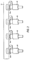
- FIG. 1A is a top plan view of a cylinder head 10.
- FIG. 1B is a cross-sectional view of cylinder head 10, taken along line B-B of FIG. 1A .
- engine 1 is a multiple cylinder engine.
- two of the multiple cylinders on a cam driving mechanism side of engine 1 are shown in FIGS. 1A and 1B .
- engine 1 may have more than two cylinders.
- each cylinder has associated with it, a fuel injection valve 22 having a fuel injection nozzle, and an ignition plug 23.
- fuel rail 21 is a common fuel rail that is generally aligned along an axis that extends through a crank shaft (i.e., a cylinder alignment line direction).
- a centre line of fuel rail 21 is formed so as to be approximately parallel to the rotation axis of the crank shaft.
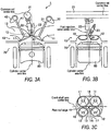
- a distance between the centre line of fuel rail 21 and a centre axis line of each cylinder is greater than a distance between a centre line of the fuel injection hole 13 and the centre axis line of the cylinder, as shown in FIG. 3A .
- fuel rail 21 may further comprise a plurality of boss portions 21a integrally formed thereon.
- boss portions 21 a holes are formed so that attachment mechanisms, such as bolts, penetrate these holes respectively, thereby securing fuel rail 21 to cylinder head 10.
- surfaces where each boss 21 a is brought into contact with cylinder head 10 are formed so as to be on the same plane. This structure increases assembly accuracy. Further, sealability of fuel injection valves 22 to fuel rail 21 is also improved, thereby preventing fuel from leaking from fuel rail 21.
- each fuel injection valve 22 is disposed between boss portions 21a.
- one end of the fuel injection valves 22 are installed in fuel rail 21, as described below, and, once connected to fuel rail 21, a second end of fuel injection valves 22, are inserted into respective through holes formed in cylinder head 10.
- Fuel injection valves 22 are fixed to cylinder head 10 by the cooperation of the attachment mechanisms penetrating through bosses 21a so that fuel injection valves 22 are fixed thereto due to a compression force of fuel rail 21. Since the fuel injection valves 22 are disposed between boss portions 21a as described above, fuel injection valves 22 are not cantilevered. Therefore, even though combustion force acts on fuel injection valves 22, a bending force is not applied to fuel rail 21.
- fuel injection valves 22 when viewing fuel injection valves 22 in a direction perpendicular to the crank shaft axis, fuel injection valves 22 are disposed so as to form approximately right angles with respect to cylinder head 10 and fuel rail 21, respectively. In other words, an axis extending through fuel injection valve 22 are approximately perpendicular to the fuel rail 21 centre line (as best seen in FIG. 3A ). Therefore, even though fuel injection valves 22 receive a combustion force, no bending force to the fuel injection valve body is generated.
- Ignition plugs 23 are generally aligned along the crank shaft axis together with fuel injection valves 22. A terminal at the top of each ignition plug 23 is inclined so as to be spaced away from an adjacent fuel injection valve 22. Ignition plugs 23 are provided so as to be spaced away from a cam driving mechanism (which comprises sprockets 51 and chain 52), as compared with fuel injection valves 22. Thus, each ignition plug 23 is disposed so as to be away from the cam driving mechanism, as best seen in FIG. 1A . With this arrangement sprockets 51 and chain 52 may be properly positioned so as to operate intake and exhaust air valve cams 32, 42 without interference from ignition plugs 23.
- intake air valve cam 32 and the exhaust air valve cam 42 are operated by the cam driving mechanism, which comprises sprockets 51 and chain 52. More specifically, sprockets 51 are attached to an end of intake air valve cam 32 and an end of the exhaust air valve 42. The rotation of the crank shaft is transmitted to sprockets 51 through chain 52 so as to drive intake air valve cam 32 and exhaust air valve cam 42.
- the cam driving mechanism which comprises sprockets 51 and chain 52. More specifically, sprockets 51 are attached to an end of intake air valve cam 32 and an end of the exhaust air valve 42. The rotation of the crank shaft is transmitted to sprockets 51 through chain 52 so as to drive intake air valve cam 32 and exhaust air valve cam 42.
- each fuel injection valve 22 is disposed through a seal 22a without inclining with respect to the axis extending through fuel rail 21.
- Each fuel injection valve 22 is arranged to as to be disposed generally perpendicular to fuel rail 21.
- two or more fuel injection valves 22 are directly connected to one common fuel rail 21, so that a separate link pipe is not necessary.
- use of a common fuel rail 21 permits a reduced number of parts, which may also translate into a reduction in cost. Indeed, when the engine 1 is manufactured, it is possible to attach the fuel injection valves 22 to the common fuel rail 21, first, and then fix them together with the common fuel rail 21 to cylinder head 10 so that the number of assembly processing steps may be reduced.
- Engine 1 includes cylinder head 10, a cylinder block 70, and a piston 80.
- Piston 80 has a cavity 81 disposed therein.
- cavity 81 has a generally circular shape when viewed from the top of cylinder head 10.
- a centre of the cavity 81 is positioned, in a cylinder axis direction, under an injection point of a tip of the fuel injection valve 22.
- An intake side roof 16 and an exhaust side roof 17 are formed in cylinder head 10 so as to form a pent roof.
- An edge line (ridgeline) 15 of the pent roof is located between intake side roof 16 and exhaust side roof 17. As may be seen in FIG. 3C , in one embodiment, edge line 15 is slightly offset from crank shaft axis.
- Intake air ports 11 are formed in intake side roof 16.
- Exhaust air ports 12 are formed in exhaust side roof 17.
- Intake air ports 11 are opened/closed by intake air valve 31, which is driven by intake air valve cam 32.
- Exhaust ports 12 are opened/closed by exhaust air valve 41 that is driven by exhaust air valve cam 42.
- a fuel injection valve 22 and an ignition plug 23 are attached to the cylinder head 10.
- Fuel injection valves 22 inject fuel supplied from the high pressure common fuel rail 21. Fuel injection valves 22 inject fuel from the fuel injection nozzle f acing the combustion chamber through the fuel injection hole 13. The fuel injection valve 22 is pressed by fuel rail 21 located above fuel injection valve 22.
- Ignition plug 23 faces a fuel combustion chamber formed in cylinder head 10 through an ignition hole 14 (as seen in FIG. 3C ) formed adjacent to the fuel injection hole 13. Ignition plug 23 is disposed at a position where the ignition portion at the tip thereof is adjacent to the fuel injection valve 22, and fuel injected from the injection nozzle of the fuel injection valve 22 can be directly ignited, or an air-fuel mixture may be generated to form a fuel mist, whereby the fuel mist may be ignited.
- fuel injection hole 13 and ignition hole 14 are positioned so as to be slightly offset toward an exhaust air port side from the crank shaft axis centre line. That is, the centre of fuel injection hole 13 and ignition hole 14 is formed in the exhaust air side roof 17.
- fuel injection hole 13 is formed on a side of the cam driving mechanism from the centre of the fuel combustion chamber.
- the ignition hole 14 is formed on an opposite side to the cam driving mechanism from the centre of the fuel combustion chamber. Because the ignition hole 14 is not disposed between intake air ports 11, this arrangement permits the opening area of intake air port 11 to be larger than exhaust air port 12. The increase size of the opening area of intake air port 11 permits improved intake air efficiency such that the output power of engine 1 may be improved.
- fuel injection valve 22 is disposed on a cam driving mechanism side of cylinder head 10
- ignition plug 23 is disposed on a side opposite to the cam driving mechanism, it is possible to position fuel injection valve 22 and ignition plug 23 in a space formed between two intake air ports 11 and two exhaust air ports 12 in a balanced manner. Therefore, it is possible to maintain an appropriate distance from each air valve, each port, each valve seat and the like, so that appropriate thicknesses of various parts of the cylinder head 10 may be obtained to increase durability of the engine.
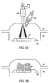
- FIG. 4 is an enlarged view of an area surrounding the tip of fuel injection valve 22 and the ignition plug 23.
- a space for a water path 18 between fuel ignition valve 22 and ignition plug 23 is defined due to incline of ignition plug 23.
- the cooling capability of fuel ignition valve 22 and the ignition plug 23 is enhanced by the inclusion of water path 18, and it is possible to avoid caulking of fuel injection valve 22 or knocking.
- the space for water path 18 may be further enlarged, thereby further improving the cooling capability.
- fuel injection valve 22 is inclined toward only the side of exhaust air valves 41 when viewing from the crank shaft direction ( FIG. 3A ).
- fuel injection valve 22 is provided to form an approximately right angle with respect to cylinder head 10 and common fuel rail 21 ( FIG. 3B ). Therefore, the combustion pressure acts in a direction perpendicular to fuel rail, so that it does not act as a force to bend fuel injection valve 22 with respect to common fuel rail 21. Accordingly, this configuration improves sealability between fuel injection valve 22 and the common fuel rail 21.
- the distance between fuel injection valve 22 and ignition plug 23 becomes too small. Indeed, in such a case, to accomplish a layout of a fuel injection valve 22 and a ignition plug 23, the ignition plug 23 would need to be substantially inclined toward the side of intake air valve 31 so that an appropriate distance between the ignition plug 23 and the fuel injection valve 22 may be accomplished. However, in such a structure, the size of intake air port 11 may be adversely reduced. In addition, it is difficult to achieve a layout of intake air valve 31 and exhaust air valve 41, which may result in an open angle of intake air valve 31 and exhaust air valve 41 becomes undesirably large. In such instances, the depth of the combustion chamber increases, such that the surface area of the combustion chamber increases. The increase in surface area of the combustion changer increases cooling loss resulting in a deterioration of gas mileage.
- in-cylinder direct fuel injection engine 1 by inclining fuel injection valve 22 toward the side of the exhaust air valve 41 ( FIG. 3A ), in which fuel injection valve 22 is provided so as to form an approximately right angle with cylinder head 10 and common fuel rail 21 ( FIG. 3B ), the problem of potential reduction of the size of intake air port 11 may be eliminated.
- fuel injection hole 13 and ignition hole 14 is formed around the approximate centre of the roof located between the openings of intake air ports 11 and the exhaust ports 12 of cylinder head 10, on the exhaust air side of cylinder head, and provided so as to be generally aligned along the direction of the crank shaft (i.e., parallel to the crank shaft axis centre line shown in FIG. 3C ). Therefore, it is possible to enlarge the openings of intake air ports 11 (i.e., increase the intake air valve diameter), so that intake air efficiency is not compromised.
- the fuel in a uniform driving condition in which fuel is injected during an air intake process, the fuel is hard to attach to the side wall of the cylinder. Thus, it is possible to prevent deterioration of lubricating ability due to increase of blow-by gas or thinness of gasoline.
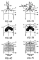
- FIGs. 6A-6C and 7A-7C illustrate a second embodiment of the in-cylinder direct fuel injection engine.
- FIGs. 6A-6C are diagrams viewed from the front side of the engine, corresponding to FIG. 3A .
- FIGs. 7A-7C are diagrams viewed from an intake air side of the engine, corresponding to FIG. 3B .
- FIG. 6A and FIG. 7A illustrate a state in which fuel is injected and the piston is at the top dead centre of the combustion chamber.
- FIGS. 6B and 7B illustrate a state in which a piston is moving downwardly.
- FIGS. 6C and 7C illustrate a state in which the piston positioned at the bottom of the combustion chamber.
- Fuel injection valve 22 used for the present embodiment injects fuel in the centre axis direction of the injection valve. In addition, a uniform driving is carried out during a process of the injection, the fuel is injected.
- the body of the fuel injection valve 22 is inclined toward the side of the exhaust air valve 41 as shown in FIG. 6A . Therefore, the fuel injection valve 22 injects the fuel against the intake air. If the fuel injection valve 22 is inclined toward the side of the intake air valve 31, the fuel injection valve 22 injects the fuel toward the intake air direction. In such a case, the fuel tends to adhere to the side wall of the cylinder on the exhaust port side since the fuel flows with the intake air, so that there is a possibility that a blow-by gas increases.
- the main body of the fuel injection valve 22 is inclined toward the side of the exhaust air valve 41, as shown in FIG. 6B , it is difficult for the fuel to adhere to the side wall of the cylinder so that deterioration of lubricating ability due to increase of the blow-by gas or dilution of gas can be prevented.
- mixture with intake air is promoted so that exhaust emission can be decreased and output power is enhanced.
- the fuel is injected in a centre axis line direction of the injection valve 22, the fuel is injected against the intake air; the fuel can be injected across a wide area so that it is possible to prevent uneven density of mixed air in the cylinder ( FIGS. 6C and 7C ).
Landscapes
- Engineering & Computer Science (AREA)
- Mechanical Engineering (AREA)
- General Engineering & Computer Science (AREA)
- Chemical & Material Sciences (AREA)
- Combustion & Propulsion (AREA)
- Cylinder Crankcases Of Internal Combustion Engines (AREA)
- Fuel-Injection Apparatus (AREA)
- Combustion Methods Of Internal-Combustion Engines (AREA)
- Ignition Installations For Internal Combustion Engines (AREA)
Applications Claiming Priority (1)
| Application Number | Priority Date | Filing Date | Title |
|---|---|---|---|
| JP2005304731A JP4742802B2 (ja) | 2005-10-19 | 2005-10-19 | 筒内直噴エンジン |
Publications (2)
| Publication Number | Publication Date |
|---|---|
| EP1777403A1 EP1777403A1 (en) | 2007-04-25 |
| EP1777403B1 true EP1777403B1 (en) | 2016-01-20 |
Family
ID=37726982
Family Applications (1)
| Application Number | Title | Priority Date | Filing Date |
|---|---|---|---|
| EP06255371.4A Not-in-force EP1777403B1 (en) | 2005-10-19 | 2006-10-18 | Direct injection engine |
Country Status (4)
| Country | Link |
|---|---|
| US (1) | US7475675B2 (ja) |
| EP (1) | EP1777403B1 (ja) |
| JP (1) | JP4742802B2 (ja) |
| CN (1) | CN100455778C (ja) |
Families Citing this family (8)
| Publication number | Priority date | Publication date | Assignee | Title |
|---|---|---|---|---|
| FR2950396B1 (fr) * | 2009-09-22 | 2012-04-27 | Mark Iv Systemes Moteurs Sa | Module fonctionnel integrant un repartiteur et une rampe d'injection et son procede de fabrication |
| EP2372140B1 (en) * | 2010-03-25 | 2012-12-12 | Continental Automotive GmbH | Coupling device |
| GB2489484B (en) | 2011-03-30 | 2015-12-16 | Ilmor Engineering Ltd | Cylinder head configuration for internal combustion engine |
| US8997724B2 (en) * | 2013-02-25 | 2015-04-07 | Kubota Corporation | Spark-ignition engine |
| CN103256159B (zh) * | 2013-05-13 | 2015-05-27 | 安徽华菱汽车有限公司 | 一种柴油发动机电控共轨系统及柴油发动机 |
| JP6187452B2 (ja) * | 2014-12-25 | 2017-08-30 | マツダ株式会社 | 直噴エンジンの燃焼室構造 |
| CN112648099B (zh) * | 2019-10-11 | 2022-07-22 | 广州汽车集团股份有限公司 | 一种气缸盖总成及包括其的发动机 |
| CN115111094A (zh) * | 2022-07-29 | 2022-09-27 | 苏州百胜动力机器股份有限公司 | 一种舷外机发动机的高压直喷缸体机构 |
Family Cites Families (24)
| Publication number | Priority date | Publication date | Assignee | Title |
|---|---|---|---|---|
| JP3280489B2 (ja) * | 1993-09-30 | 2002-05-13 | マツダ株式会社 | エンジンのシリンダヘッド構造およびその製造方法 |
| JP3333298B2 (ja) * | 1993-12-30 | 2002-10-15 | ヤマハ発動機株式会社 | 筒内燃料噴射式の多気筒エンジン |
| DE19713028C2 (de) * | 1996-04-01 | 2000-02-24 | Avl List Gmbh | Viertakt-Brennkraftmaschine mit Fremdzündung |
| JP3686972B2 (ja) * | 1996-12-17 | 2005-08-24 | 日産自動車株式会社 | 筒内直噴型火花点火式内燃機関 |
| JP4108806B2 (ja) | 1997-02-10 | 2008-06-25 | 富士重工業株式会社 | 筒内直噴式火花点火エンジンの燃焼室構造 |
| JP3722177B2 (ja) * | 1997-05-30 | 2005-11-30 | ヤマハ発動機株式会社 | 筒内噴射ガソリンエンジン |
| FR2765629B1 (fr) * | 1997-07-01 | 2002-02-01 | Renault | Moteur a injection directe et allumage commande |
| JPH1136978A (ja) * | 1997-07-16 | 1999-02-09 | Unisia Jecs Corp | 内燃機関用ピストン |
| JP3626332B2 (ja) * | 1997-09-12 | 2005-03-09 | 本田技研工業株式会社 | エンジン |
| JPH11351095A (ja) * | 1998-06-11 | 1999-12-21 | Toyota Motor Corp | 筒内噴射式内燃機関のデリバリパイプ |
| JP2001090629A (ja) * | 1999-09-22 | 2001-04-03 | Nippon Soken Inc | 筒内直噴式内燃機関の燃料供給システム |
| JP2001221127A (ja) * | 2000-02-09 | 2001-08-17 | Nissan Motor Co Ltd | 内燃機関の燃料噴射装置 |
| DE50112871D1 (de) | 2001-12-14 | 2007-09-27 | Ford Global Tech Llc | Brennkraftmaschine mit Direkteinspritzung |
| CN2526516Y (zh) * | 2002-03-11 | 2002-12-18 | 合肥工业大学 | 一种发动机电控共轨式多种燃料喷射装置 |
| JP3991789B2 (ja) * | 2002-07-04 | 2007-10-17 | トヨタ自動車株式会社 | 混合気を圧縮自着火させる内燃機関 |
| US6877491B2 (en) * | 2002-07-31 | 2005-04-12 | Honda Giken Kogyo Kabushiki Kaisha | Air fuel injection engine |
| JP2004169554A (ja) * | 2002-11-15 | 2004-06-17 | Denso Corp | 蓄圧式燃料噴射装置 |
| JP2004211637A (ja) * | 2003-01-07 | 2004-07-29 | Denso Corp | 高圧燃料蓄圧器 |
| DE10342387B3 (de) * | 2003-09-13 | 2005-05-25 | Man B & W Diesel Ag | Umrüstsystem |
| US7028662B2 (en) * | 2003-11-06 | 2006-04-18 | Nissan Motor Co., Ltd. | Direct fuel injection engine |
| JP3982482B2 (ja) * | 2003-11-06 | 2007-09-26 | 日産自動車株式会社 | 筒内直接噴射式内燃機関の燃焼室構造 |
| JP4257520B2 (ja) * | 2003-12-22 | 2009-04-22 | 三菱自動車工業株式会社 | 筒内噴射型内燃機関 |
| JP4099668B2 (ja) * | 2004-03-29 | 2008-06-11 | 株式会社デンソー | 燃料噴射弁の取り付け構造およびそれに用いる固定部材 |
| JP2006052666A (ja) * | 2004-08-11 | 2006-02-23 | Nissan Motor Co Ltd | 筒内直接噴射式内燃機関 |
-
2005
- 2005-10-19 JP JP2005304731A patent/JP4742802B2/ja not_active Expired - Fee Related
-
2006
- 2006-10-18 US US11/582,672 patent/US7475675B2/en active Active
- 2006-10-18 EP EP06255371.4A patent/EP1777403B1/en not_active Not-in-force
- 2006-10-19 CN CNB2006101362630A patent/CN100455778C/zh not_active Expired - Fee Related
Also Published As
| Publication number | Publication date |
|---|---|
| US20070084436A1 (en) | 2007-04-19 |
| CN1952360A (zh) | 2007-04-25 |
| CN100455778C (zh) | 2009-01-28 |
| JP2007113464A (ja) | 2007-05-10 |
| JP4742802B2 (ja) | 2011-08-10 |
| EP1777403A1 (en) | 2007-04-25 |
| US7475675B2 (en) | 2009-01-13 |
Similar Documents
| Publication | Publication Date | Title |
|---|---|---|
| EP1777403B1 (en) | Direct injection engine | |
| US5735240A (en) | Direct injected engine | |
| US6095114A (en) | Gasoline direct-injection engine | |
| EP1069291B1 (en) | In-cylinder direct-injection spark-ignition engine | |
| US7188589B2 (en) | Direct injection internal combustion engine | |
| JP2001329930A (ja) | 筒内噴射式エンジンの燃料インジェクタ取付構造 | |
| KR19980087412A (ko) | 내연 기관 | |
| EP1475530B1 (en) | Direct injection type internal combustion engine | |
| US6928978B2 (en) | In-cylinder direct-injection engine and cylinder head | |
| US6811101B2 (en) | Fuel injection valve body for direct injection type internal combustion engine | |
| US7137380B1 (en) | Internal combustion engine with ignition plug and vehicle provided with the same | |
| JP3982482B2 (ja) | 筒内直接噴射式内燃機関の燃焼室構造 | |
| US7571708B2 (en) | Spark ignited direct injection targeting for improved combustion | |
| JP3867319B2 (ja) | 筒内直噴式内燃機関 | |
| KR100946484B1 (ko) | 가솔린 직접 분사 엔진용 피스톤 헤드 | |
| JP4248521B2 (ja) | 筒内直接噴射式内燃機関 | |
| JP2016114013A (ja) | 内燃機関の吸気ポート断熱構造 | |
| JP3738478B2 (ja) | 直噴火花点火式内燃機関 | |
| US7565893B2 (en) | Spark ignited direct injection flow geometry for improved combustion | |
| WO2024201624A1 (ja) | 筒内噴射式内燃機関 | |
| US20020029763A1 (en) | Structure of arranging fuel injection valve of engine | |
| WO2024201620A1 (ja) | 筒内噴射式内燃機関 | |
| WO2024201623A1 (ja) | 内燃機関 | |
| KR100999279B1 (ko) | 가솔린직접분사 엔진의 연료펌프 장착구조 | |
| JPH0658105B2 (ja) | エンジンの吸気装置 |
Legal Events
| Date | Code | Title | Description |
|---|---|---|---|
| PUAI | Public reference made under article 153(3) epc to a published international application that has entered the european phase |
Free format text: ORIGINAL CODE: 0009012 |
|
| AK | Designated contracting states |
Kind code of ref document: A1 Designated state(s): AT BE BG CH CY CZ DE DK EE ES FI FR GB GR HU IE IS IT LI LT LU LV MC NL PL PT RO SE SI SK TR |
|
| AX | Request for extension of the european patent |
Extension state: AL BA HR MK YU |
|
| 17P | Request for examination filed |
Effective date: 20071025 |
|
| AKX | Designation fees paid |
Designated state(s): DE FR GB |
|
| 17Q | First examination report despatched |
Effective date: 20071218 |
|
| GRAP | Despatch of communication of intention to grant a patent |
Free format text: ORIGINAL CODE: EPIDOSNIGR1 |
|
| GRAS | Grant fee paid |
Free format text: ORIGINAL CODE: EPIDOSNIGR3 |
|
| INTG | Intention to grant announced |
Effective date: 20151112 |
|
| RIN1 | Information on inventor provided before grant (corrected) |
Inventor name: TSUCHIDA, HIROFUMI, C/O NISSAN MOTOR CO., LTD Inventor name: FUKUZUMI, MASAHIRO, C/O NISSAN MOTOR CO., LTD Inventor name: HIRAYA, KOJI, C/O NISSAN MOTOR CO., LTD Inventor name: KONO, TOSHIYA, C/O NISSAN MOTOR CO., LTD |
|
| GRAA | (expected) grant |
Free format text: ORIGINAL CODE: 0009210 |
|
| AK | Designated contracting states |
Kind code of ref document: B1 Designated state(s): DE FR GB |
|
| REG | Reference to a national code |
Ref country code: GB Ref legal event code: FG4D |
|
| REG | Reference to a national code |
Ref country code: DE Ref legal event code: R096 Ref document number: 602006047776 Country of ref document: DE |
|
| REG | Reference to a national code |
Ref country code: FR Ref legal event code: PLFP Year of fee payment: 11 |
|
| REG | Reference to a national code |
Ref country code: DE Ref legal event code: R097 Ref document number: 602006047776 Country of ref document: DE |
|
| PLBE | No opposition filed within time limit |
Free format text: ORIGINAL CODE: 0009261 |
|
| STAA | Information on the status of an ep patent application or granted ep patent |
Free format text: STATUS: NO OPPOSITION FILED WITHIN TIME LIMIT |
|
| 26N | No opposition filed |
Effective date: 20161021 |
|
| REG | Reference to a national code |
Ref country code: FR Ref legal event code: PLFP Year of fee payment: 12 |
|
| REG | Reference to a national code |
Ref country code: FR Ref legal event code: PLFP Year of fee payment: 13 |
|
| PGFP | Annual fee paid to national office [announced via postgrant information from national office to epo] |
Ref country code: FR Payment date: 20190913 Year of fee payment: 14 |
|
| PGFP | Annual fee paid to national office [announced via postgrant information from national office to epo] |
Ref country code: DE Payment date: 20191008 Year of fee payment: 14 |
|
| PGFP | Annual fee paid to national office [announced via postgrant information from national office to epo] |
Ref country code: GB Payment date: 20191018 Year of fee payment: 14 |
|
| REG | Reference to a national code |
Ref country code: DE Ref legal event code: R119 Ref document number: 602006047776 Country of ref document: DE |
|
| GBPC | Gb: european patent ceased through non-payment of renewal fee |
Effective date: 20201018 |
|
| PG25 | Lapsed in a contracting state [announced via postgrant information from national office to epo] |
Ref country code: FR Free format text: LAPSE BECAUSE OF NON-PAYMENT OF DUE FEES Effective date: 20201031 Ref country code: DE Free format text: LAPSE BECAUSE OF NON-PAYMENT OF DUE FEES Effective date: 20210501 |
|
| PG25 | Lapsed in a contracting state [announced via postgrant information from national office to epo] |
Ref country code: GB Free format text: LAPSE BECAUSE OF NON-PAYMENT OF DUE FEES Effective date: 20201018 |