EP1069291B1 - In-cylinder direct-injection spark-ignition engine - Google Patents
In-cylinder direct-injection spark-ignition engine Download PDFInfo
- Publication number
- EP1069291B1 EP1069291B1 EP00111713A EP00111713A EP1069291B1 EP 1069291 B1 EP1069291 B1 EP 1069291B1 EP 00111713 A EP00111713 A EP 00111713A EP 00111713 A EP00111713 A EP 00111713A EP 1069291 B1 EP1069291 B1 EP 1069291B1
- Authority
- EP
- European Patent Office
- Prior art keywords
- combustion chamber
- piston
- bowl cavity
- piston bowl
- tumble flow
- Prior art date
- Legal status (The legal status is an assumption and is not a legal conclusion. Google has not performed a legal analysis and makes no representation as to the accuracy of the status listed.)
- Expired - Lifetime
Links
Images


Classifications
-
- F—MECHANICAL ENGINEERING; LIGHTING; HEATING; WEAPONS; BLASTING
- F02—COMBUSTION ENGINES; HOT-GAS OR COMBUSTION-PRODUCT ENGINE PLANTS
- F02B—INTERNAL-COMBUSTION PISTON ENGINES; COMBUSTION ENGINES IN GENERAL
- F02B17/00—Engines characterised by means for effecting stratification of charge in cylinders
- F02B17/005—Engines characterised by means for effecting stratification of charge in cylinders having direct injection in the combustion chamber
-
- F—MECHANICAL ENGINEERING; LIGHTING; HEATING; WEAPONS; BLASTING
- F02—COMBUSTION ENGINES; HOT-GAS OR COMBUSTION-PRODUCT ENGINE PLANTS
- F02B—INTERNAL-COMBUSTION PISTON ENGINES; COMBUSTION ENGINES IN GENERAL
- F02B23/00—Other engines characterised by special shape or construction of combustion chambers to improve operation
- F02B23/08—Other engines characterised by special shape or construction of combustion chambers to improve operation with positive ignition
- F02B23/10—Other engines characterised by special shape or construction of combustion chambers to improve operation with positive ignition with separate admission of air and fuel into cylinder
- F02B23/104—Other engines characterised by special shape or construction of combustion chambers to improve operation with positive ignition with separate admission of air and fuel into cylinder the injector being placed on a side position of the cylinder
- F02B23/105—Other engines characterised by special shape or construction of combustion chambers to improve operation with positive ignition with separate admission of air and fuel into cylinder the injector being placed on a side position of the cylinder the fuel is sprayed directly onto or close to the spark plug
-
- F—MECHANICAL ENGINEERING; LIGHTING; HEATING; WEAPONS; BLASTING
- F02—COMBUSTION ENGINES; HOT-GAS OR COMBUSTION-PRODUCT ENGINE PLANTS
- F02B—INTERNAL-COMBUSTION PISTON ENGINES; COMBUSTION ENGINES IN GENERAL
- F02B31/00—Modifying induction systems for imparting a rotation to the charge in the cylinder
-
- F—MECHANICAL ENGINEERING; LIGHTING; HEATING; WEAPONS; BLASTING
- F02—COMBUSTION ENGINES; HOT-GAS OR COMBUSTION-PRODUCT ENGINE PLANTS
- F02B—INTERNAL-COMBUSTION PISTON ENGINES; COMBUSTION ENGINES IN GENERAL
- F02B23/00—Other engines characterised by special shape or construction of combustion chambers to improve operation
- F02B23/08—Other engines characterised by special shape or construction of combustion chambers to improve operation with positive ignition
- F02B23/10—Other engines characterised by special shape or construction of combustion chambers to improve operation with positive ignition with separate admission of air and fuel into cylinder
- F02B2023/106—Tumble flow, i.e. the axis of rotation of the main charge flow motion is horizontal
-
- F—MECHANICAL ENGINEERING; LIGHTING; HEATING; WEAPONS; BLASTING
- F02—COMBUSTION ENGINES; HOT-GAS OR COMBUSTION-PRODUCT ENGINE PLANTS
- F02B—INTERNAL-COMBUSTION PISTON ENGINES; COMBUSTION ENGINES IN GENERAL
- F02B75/00—Other engines
- F02B75/02—Engines characterised by their cycles, e.g. six-stroke
- F02B2075/022—Engines characterised by their cycles, e.g. six-stroke having less than six strokes per cycle
- F02B2075/027—Engines characterised by their cycles, e.g. six-stroke having less than six strokes per cycle four
-
- F—MECHANICAL ENGINEERING; LIGHTING; HEATING; WEAPONS; BLASTING
- F02—COMBUSTION ENGINES; HOT-GAS OR COMBUSTION-PRODUCT ENGINE PLANTS
- F02B—INTERNAL-COMBUSTION PISTON ENGINES; COMBUSTION ENGINES IN GENERAL
- F02B75/00—Other engines
- F02B75/12—Other methods of operation
- F02B2075/125—Direct injection in the combustion chamber for spark ignition engines, i.e. not in pre-combustion chamber
-
- F—MECHANICAL ENGINEERING; LIGHTING; HEATING; WEAPONS; BLASTING
- F02—COMBUSTION ENGINES; HOT-GAS OR COMBUSTION-PRODUCT ENGINE PLANTS
- F02B—INTERNAL-COMBUSTION PISTON ENGINES; COMBUSTION ENGINES IN GENERAL
- F02B2275/00—Other engines, components or details, not provided for in other groups of this subclass
- F02B2275/48—Tumble motion in gas movement in cylinder
-
- F—MECHANICAL ENGINEERING; LIGHTING; HEATING; WEAPONS; BLASTING
- F02—COMBUSTION ENGINES; HOT-GAS OR COMBUSTION-PRODUCT ENGINE PLANTS
- F02F—CYLINDERS, PISTONS OR CASINGS, FOR COMBUSTION ENGINES; ARRANGEMENTS OF SEALINGS IN COMBUSTION ENGINES
- F02F1/00—Cylinders; Cylinder heads
- F02F1/24—Cylinder heads
- F02F2001/241—Cylinder heads specially adapted to pent roof shape of the combustion chamber
-
- F—MECHANICAL ENGINEERING; LIGHTING; HEATING; WEAPONS; BLASTING
- F02—COMBUSTION ENGINES; HOT-GAS OR COMBUSTION-PRODUCT ENGINE PLANTS
- F02F—CYLINDERS, PISTONS OR CASINGS, FOR COMBUSTION ENGINES; ARRANGEMENTS OF SEALINGS IN COMBUSTION ENGINES
- F02F1/00—Cylinders; Cylinder heads
- F02F1/24—Cylinder heads
- F02F2001/244—Arrangement of valve stems in cylinder heads
- F02F2001/245—Arrangement of valve stems in cylinder heads the valve stems being orientated at an angle with the cylinder axis
-
- F—MECHANICAL ENGINEERING; LIGHTING; HEATING; WEAPONS; BLASTING
- F02—COMBUSTION ENGINES; HOT-GAS OR COMBUSTION-PRODUCT ENGINE PLANTS
- F02F—CYLINDERS, PISTONS OR CASINGS, FOR COMBUSTION ENGINES; ARRANGEMENTS OF SEALINGS IN COMBUSTION ENGINES
- F02F3/00—Pistons
- F02F3/26—Pistons having combustion chamber in piston head
-
- Y—GENERAL TAGGING OF NEW TECHNOLOGICAL DEVELOPMENTS; GENERAL TAGGING OF CROSS-SECTIONAL TECHNOLOGIES SPANNING OVER SEVERAL SECTIONS OF THE IPC; TECHNICAL SUBJECTS COVERED BY FORMER USPC CROSS-REFERENCE ART COLLECTIONS [XRACs] AND DIGESTS
- Y02—TECHNOLOGIES OR APPLICATIONS FOR MITIGATION OR ADAPTATION AGAINST CLIMATE CHANGE
- Y02T—CLIMATE CHANGE MITIGATION TECHNOLOGIES RELATED TO TRANSPORTATION
- Y02T10/00—Road transport of goods or passengers
- Y02T10/10—Internal combustion engine [ICE] based vehicles
- Y02T10/12—Improving ICE efficiencies
Definitions
- the present invention relates to the improvements of an in-cylinder direct-injection spark-ignition internal combustion engine equipped with an open combustion chamber type piston in which fuel is injected directly into engine cylinders and it is ignited by an electric spark, and specifically to techniques for effectively producing strong stable tumble flow for stable combustion (particularly, stable stratified charge combustion), and capable of improving exhaust emission.
- a combustion mode is changeable between a homogeneous combustion mode (an early injection combustion mode) where fuel-injection early in the intake stroke produces a homogeneous air-fuel mixture, and a stratified charge combustion mode (a late injection combustion mode) where late fuel-injection delays the event until near the end of the compression stroke to produce a stratified air-fuel mixture.
- stratified charging or stratified combustion mode is effective under a low engine-load operating condition where the amount of fuel injected is comparatively less.
- the direct-injection spark-ignition engine disclosed in the Japanese Patent Provisional Publication No. 9-317479 has a spark plug centrally located at a center of the combustion chamber, a fuel injector located at a side wall portion of the combustion chamber and near an intake valve disposed in an intake port, and a piston having a piston bowl cavity combustion chamber in a piston crown.
- the engine disclosed in the Japanese Patent Provisional Publication No.9-317479 is operable in a stratified charge combustion mode where fuel injection is executed on a compression stroke while introducing a reverse tumble flow to an induced air drawn into the combustion chamber through the intake port. Such a piston bowl cavity acts to promote strong tumble flow.
- the above reverse tumble flow is a vertical-vortex tumble flow being directed downward from the intake valve, flowing via the vicinity of the fuel injector toward the piston crown, then turned reversely along the piston bowl cavity, and thus directed toward the spark plug.
- the piston bowl cavity is dimensioned so that the angle between opposite side edge portions of the piston bowl cavity, gradually widening in a direction along a line extending from the intake valve side to the center of the piston crown (or in a direction along streamlines of the tumble flow along the bowl cavity), is substantially equal to a fuel-spray angle.
- the angle between opposite side edge portions of the piston bowl cavity will be hereinafter referred to as a "bowl-cavity opposite-side-edges tapering angle".
- the engine includes difficulty in concentrating the fuel spray in a desired point while the fuel is guided by the piston bowl cavity having the above-mentioned structural dimensions and geometry and carried on the reverse tumble flow.
- the fuel spray injected from the injector on the compression stroke during the stratified charge combustion mode, cannot be certainly carried on the reverse tumble flow and delivered to the vicinity of the tip of the spark plug.
- the optimally-controlled fling-up action is obtained by full cooperation of a strong in-cylinder normal tumble flow concentrating to a desired point and a relatively wide angle between opposite side edge portions of the piston bowl cavity, gradually widening in a direction along a line extending from the intake valve side to the center of the piston crown or gradually narrowing in a direction along the normal tumble-flow streamline on the bowl cavity, as compared to a fuel-spray angle.
- a direct-injection spark-ignition engine operable in at least a stratified charge combustion mode where fuel injection is executed on a compression stroke while introducing a vertical-vortex tumble flow to an induced air drawn into a combustion chamber through an intake port, comprises a cylinder block having a cylinder, a piston movable through a stroke in the cylinder and having a piston bowl cavity combustion chamber in a piston crown, a cylinder head mounted on the cylinder block, a spark plug centrally located at a center of the combustion chamber, and a fuel injector valve provided at a side wall portion of the combustion chamber and near an intake valve disposed in the intake port for injecting fuel directly into the combustion chamber.
- the piston bowl cavity combustion chamber is formed in the piston crown for producing a normal tumble flow being directed toward a vicinity of said fuel injector valve and then directed toward a vicinity of the spark plug while being guided by the piston bowl cavity combustion chamber.
- the width of the piston bowl cavity combustion chamber is relatively wide at an exhaust valve side and relatively narrow at an intake valve side.
- a depth of the piston bowl cavity combustion chamber is relatively shallow at the exhaust valve side and relatively deep at the intake valve side.
- the in-cylinder direct-injection spark-ignition engine of the invention is exemplified in a four-valve, gasoline-fuel, spark-ignition internal combustion engine having a pent-roof combustion chamber.
- the ignition plug (the spark plug) 9 is located essentially at the center of the combustion chamber 4.
- the cylinder head 2 is mounted on a cylinder block 1 having an engine cylinder.
- a piston 3 is provided in the cylinder to be movable through a stroke in the cylinder.
- the combustion chamber 4 is defined by the cylinder wall of the cylinder block 1, the bottom face of the cylinder head 2, and the top surface (or the piston crown or the piston head) of the piston 3.
- the engine is equipped with two intake ports (7, 7), offsetting from the center axial line of the cylinder bored in the cylinder block 1.
- the cylinder head 2 is equipped with two intake valve ports (7, 7), offsetting from the center axial line of the cylinder formed in a cylinder block 1, and two exhaust valve ports (8, 8), offsetting from the center axial line of the cylinder in the opposite direction to positions of the intake ports.
- the engine has a so-called cross-flow port structure.
- a fuel-injector valve 10 is provided in a side wall portion of the combustion chamber 4 and in the vicinity of the substantially middle portion of two downstream opening ends of the intake ports (7, 7), so as to inject or spray out fuel directly into the combustion chamber 4.
- Each of the intake ports (7, 7) is contoured to easily affect sufficient turbulent action, that is, a strong normal tumble flow (denoted by a in Fig. 1) to the air-fuel mixture, in the form of a vertical vortex (in-cylinder normal tumble flow) tumbling within the combustion chamber 4.
- the strong normal tumble flow indicated by the arrow a in Fig. 1 is a vertical-vortex tumble flow being directed upward from the intake valve, flowing via the vicinity of the fuel injector 10 toward the piston crown, and then turned reversely along a bowl-shaped piston bowl cavity combustion chamber 11 (fully described later), and thus directed toward the vicinity of the tip of the spark plug 9.
- the bowl-shaped piston cavity combustion chamber (simply, a piston bow cavity) 11 is formed in the piston crown of the piston 3.
- the piston bowl cavity 11 functions as a tumble-flow guide groove. Therefore, the normal tumble flow a is guided by virtue of the piston bowl cavity 11 of the piston 3, and thus directed to the vicinity of the tip of the spark plug 9. Structural details of the piston bowl cavity 11 are hereunder described.
- the piston bowl cavity 11 is formed into a circular-arc shape in a direction along streamlines of the normal tumble flow a of intake air.
- a substantially right-hand half of the piston bowl cavity closer to the exhaust valve 6 than the intake valve is formed as a moderately sloped or curved, comparatively shallow cavity portion
- a substantially left-hand half of the piston bowl cavity 11 closer to the intake valve 5 than the exhaust valve is formed as a steeply sloped or curved, comparatively deep cavity portion.
- the deepest portion ⁇ of the piston bowl cavity 11 is slightly offset from the center of the piston crown (the axis of the piston 3) toward the intake valve side.
- the offset between the deepest portion ⁇ and the center of the piston crown is dimensioned so that the ratio of the offset to the cylinder bore is within a specified range of 5 to 20%.
- the depth of the deepest portion ⁇ measured from the uppermost face of the piston crown of the piston 3, is dimensioned so that the ratio of the depth of the deepest portion ⁇ to the cylinder bore is within a specified range of 5 to 20%.
- the moderate curved line R1 included in the moderately sloped or curved, comparatively shallow cavity portion continues with the steep curved line R2, included in the steeply sloped or curved, comparatively deep cavity portion (see the substantially left-hand half of the piston bowl cavity 11 shown in Fig. 1), on the same tangential line at the deepest portion ⁇ .
- the radial distance ⁇ of each of diametrically-opposing cavity ends of the piston bowl cavity 11, in the direction along a substantially central streamline of tumble flow on the piston bowl cavity 11, to the edged portion of the circumference of the piston crown of the piston 3, is dimensioned so that the ratio of the radial distance ⁇ to the cylinder bore is within a specified range of 5 to 15%.
- the lower limit (such as 5%) of the ratio of the radial distance ⁇ to the cylinder bore is determined depending on a mechanical strength of the piston 3.
- the upper limit (such as 15%) of the ratio of the radial distance ⁇ to the cylinder bore is determined, accounting for an optimally-controlled fling-up action of air-fuel mixture caused by the normal tumble flow a.
- radial distance ⁇ is a difficulty to entry of the tumble flow (turned reversely along the pent-roof side combustion chamber) into the piston bowl cavity 11.
- the radial distance ⁇ is excessively large, the fuel spray, injected from the injector 10 on the compression stroke during the stratified charge combustion mode, cannot be effectively carried on the normal tumble flow a and delivered to the vicinity of the tip of the spark plug 9.
- the radial distance ⁇ is dimensioned so that the ratio of the radial distance ⁇ to the cylinder bore is within the specified range of 5 to 15%.
- the moderately sloped or curved, comparatively shallow cavity portion of the piston bowl cavity 11 (the exhaust-valve side shallow cavity portion) is relatively wide, whereas the steeply sloped or curved, comparatively deep cavity portion of the piston bowl cavity 11 (the intake-valve side deep cavity portion) is relatively narrow.
- the central cavity width ⁇ (defined as a line segment between and including two diametrically-opposing points located on the circumferential edge of the piston bowl cavity 11 and passing through the axis of the piston 3 in the direction perpendicular to the direction along the substantially central streamline of tumble flow on the piston bowl cavity) is dimensioned so that the ratio of the central cavity width ⁇ to the cylinder bore is within a specified range of 50 to 70%.
- a curvature of the piston bowl cavity 11 at each cross section, cut in the arbitrary plane, is dimensioned so that the cross-sectional area is substantially same over a specified range offsetting from the above line segment (passing the axis of the piston 3) by a predetermined distance s (or a predetermined offset s ) in two opposite directions along the substantially central streamline of tumble flow on the bowl cavity 11.
- the rightward offset s (or the leftward offset s ) is dimensioned so that the ratio of the offset s to the cylinder bore is within a specified range of 5 to 20%.
- the cavity width of the exhaust-valve side shallow cavity portion of the piston bowl cavity 11 is relatively wide, while the cavity width of the intake-valve side deep cavity portion of the piston bowl cavity 11 is relatively narrow.
- the edged portion of the circumference of the piston bowl cavity combustion chamber 11 formed in the piston crown of the piston 3 is dimensioned so that the angle ⁇ between opposite side edged portions of the piston bowl cavity, gradually widening from the intake valve side to the exhaust valve side or gradually narrowing in the direction along the substantially central streamline of tumble flow on the bowl cavity 11, is greater than a fuel-spray angle ⁇ of the fuel spray, injected from the injector on the compression stroke during the stratified charge combustion mode.
- the spray angle ⁇ is 50 degrees
- it is preferable to set the "bowl-cavity opposite-side-edges tapering angle" ⁇ to 60 degrees.
- the engine of the embodiment having the improved piston bowl cavity structure produces a vertical-vortex in-cylinder normal tumble flow a within the combustion chamber 4, so that the fuel spray injected by the injector 10 is directed or delivered to the vicinity of the tip of the spark plug 9.
- the normal tumble flow a is useful to avoid spray/wall impingement between fuel spray and the wall surface of the piston ball cavity 11.
- the width of the piston bowl cavity 11, functioning as a guide groove for the normal tumble flow a is relatively wide at the exhaust-valve side and relatively narrow at the intake-valve side.
- the depth of the piston bowl cavity 11 is relatively shallow at the exhaust valve side and relatively deep at the intake valve side. Therefore, as seen in Fig. 3, the piston bow cavity structure of the embodiment can smoothly and reliably carry or guide the normal tumble flow a , entering from the exhaust valve side into the piston bowl cavity 11, toward the intake valve side (the underside of the fuel injector 10) without overflowing the tumble flow out of the bowl cavity 11.
- the piston bowl cavity structure of the embodiment allows streamlines of tumble flow on the piston bowl cavity 11 to be gradually concentrated toward within the substantially central streamline of tumble flow whose central streamline passes through the center of the piston crown of the piston 3. This produces a strong normal tumble flow directed to a desired point.
- the engine of the embodiment can provide an effective fling-up action according to which fuel spray, injected from the injector 10 on the compression stroke during the stratified charge combustion mode, are flung upward and reliably directed toward the tip of the spark plug 9.
- the fuel spray can be effectively carried to the vicinity of the tip of the spark plug 9 to certainly create the richer air/fuel mixture layer around the tip of the spark plug 9 during the stratified combustion mode. This ensures a clean, stable combustion during the stratified charge combustion mode.
- Fig. 4 there is shown the result of comparison between a rate of change in indicated mean effective pressure obtained by the improved piston bowl cavity structure of the present invention and a rate of change in indicated mean effective pressure obtained by the conventional piston bowl cavity structure.
- the improved piston bowl cavity structure of the invention can reduce the rate of change in indicated mean effective pressure at a low level even at an ultra-lean air/fuel mixture ratio AFR. That is to say, the combustion stability, particularly the stratified combustion stability can be remarkably enhanced, and thus effectively enlarging the lean misfire limit. Also, the controlled strong normal tumble flow a contributes to a good delivery of the fuel spray on the tumble flow to the vicinity of the tip of the spark plug 9.
- a curvature of the piston bowl cavity 11 at each cross section is dimensioned, so that the cross-sectional area of a cross section of the bowl cavity 11, arbitrarily cut in a plane perpendicular to the direction along the substantially central streamline of tumble flow on the bowl cavity, is substantially same over a specified range offsetting from the above line segment by a predetermined offset s in two opposite directions along the substantially central streamline of tumble flow on the bowl cavity 11.
- the unique piston bowl cavity structure of the invention serves as an excellent tumble-flow guidance.
- edged portion of the circumference of the piston crown of the piston 3 is dimensioned, so that the angle ⁇ between opposite side edged portions of the piston bowl cavity, gradually widening in a direction along a line extending from the intake valve side to the center of the piston crown or gradually narrowing in the direction along the substantially central streamline of tumble flow on the bowl cavity 11, is greater than a fuel-spray angle ⁇ .
- Such a relatively wide angle ⁇ between opposite side edged portions of the piston bowl cavity 11 is effective to certainly carry the fuel spray on the tumble flow, without spray/wall impingement between fuel spray and the wall surface of the piston crown (the piston top surface).
Landscapes
- Engineering & Computer Science (AREA)
- Chemical & Material Sciences (AREA)
- Combustion & Propulsion (AREA)
- Mechanical Engineering (AREA)
- General Engineering & Computer Science (AREA)
- Combustion Methods Of Internal-Combustion Engines (AREA)
Description
- The present invention relates to the improvements of an in-cylinder direct-injection spark-ignition internal combustion engine equipped with an open combustion chamber type piston in which fuel is injected directly into engine cylinders and it is ignited by an electric spark, and specifically to techniques for effectively producing strong stable tumble flow for stable combustion (particularly, stable stratified charge combustion), and capable of improving exhaust emission.
- In recent years, there have been proposed and developed various direct-injection spark-ignition engines in which fuel is injected directly into the engine cylinders. Generally, on such direct-injection spark-ignition engines, a combustion mode is changeable between a homogeneous combustion mode (an early injection combustion mode) where fuel-injection early in the intake stroke produces a homogeneous air-fuel mixture, and a stratified charge combustion mode (a late injection combustion mode) where late fuel-injection delays the event until near the end of the compression stroke to produce a stratified air-fuel mixture. Such stratified charging or stratified combustion mode is effective under a low engine-load operating condition where the amount of fuel injected is comparatively less. In contrast to the above, during high engine-load operation where the amount of fuel sprayed out is comparatively great due to demands for more engine power or more engine output torque, there is less requirement for stratified charging, and in lieu thereof it is necessary to form more uniform air-fuel mixture layers, particularly in order to avoid the engine from knocking. One such direct-injection spark-ignition engine has been disclosed in Japanese Patent Provisional Publication No. 9-317479.
- The direct-injection spark-ignition engine disclosed in the Japanese Patent Provisional Publication No. 9-317479, has a spark plug centrally located at a center of the combustion chamber, a fuel injector located at a side wall portion of the combustion chamber and near an intake valve disposed in an intake port, and a piston having a piston bowl cavity combustion chamber in a piston crown. The engine disclosed in the Japanese Patent Provisional Publication No.9-317479 is operable in a stratified charge combustion mode where fuel injection is executed on a compression stroke while introducing a reverse tumble flow to an induced air drawn into the combustion chamber through the intake port. Such a piston bowl cavity acts to promote strong tumble flow. The above reverse tumble flow is a vertical-vortex tumble flow being directed downward from the intake valve, flowing via the vicinity of the fuel injector toward the piston crown, then turned reversely along the piston bowl cavity, and thus directed toward the spark plug. Also, the piston bowl cavity is dimensioned so that the angle between opposite side edge portions of the piston bowl cavity, gradually widening in a direction along a line extending from the intake valve side to the center of the piston crown (or in a direction along streamlines of the tumble flow along the bowl cavity), is substantially equal to a fuel-spray angle. The angle between opposite side edge portions of the piston bowl cavity will be hereinafter referred to as a "bowl-cavity opposite-side-edges tapering angle". Owing to such reverse tumble flow, there is a possibility of spray/wall impingement between fuel spray and the wall surface of the piston ball cavity. Owing to such impingement of fuel spray on the piston bowl cavity, there is an increased tendency for the incoming fuel to adhere to the piston-bowl-cavity combustion chamber wall in the form of a fuel film, and as a rapid carbonization could occur, thus deteriorating an exhaust-emission control performance by the increased amount of exhaust emissions such as smoke and particulate matter (PM) and by formation of unburned hydrocarbons (HCs). The adhered fuel film on the ball cavity results in undesired deposits in the engine, thus resulting in engine power loss and reduced piston life. Additionally, owing to the previously-discussed bowl-cavity opposite-side-edges tapering angle dimensioned to be substantially equal to the spray angle, the engine includes difficulty in concentrating the fuel spray in a desired point while the fuel is guided by the piston bowl cavity having the above-mentioned structural dimensions and geometry and carried on the reverse tumble flow. In other words, there is a possibility of undesired fuel-spray dispersion during the stratified combustion mode. This means that the fuel spray, injected from the injector on the compression stroke during the stratified charge combustion mode, cannot be certainly carried on the reverse tumble flow and delivered to the vicinity of the tip of the spark plug. Additionally, the end of the piston bowl cavity, facing to the exhaust valve side, is slightly raised, and thus there is an increased tendency for the fuel spray injected to collide with or impinge on the slightly-raised portion of the piston crown. This deteriorates fuel economy and lowers engine's output power.
- Accordingly, it is an object of the invention to provide an in-cylinder direct-injection spark-ignition engine which avoids the aforementioned disadvantages of the prior art.
- It is another object of the invention to provide an in-cylinder direct-injection spark-ignition engine having specified piston-bowl-cavity dimensions and geometry, capable of avoiding undesired spray/wall impingement by way of normal tumble flow opposite in rotation from the previously-discussed reverse tumble flow, and of certainly reliably carrying the fuel spray on the normal tumble flow and delivered to the vicinity of a tip of a spark plug to create a richer air/fuel mixture layer around the spark plug, by efficiently concentrating air flow (the normal tumble flow) in a desired point as much as possible.
- It is a further object of the invention to provide an in-cylinder direct-injection spark-ignition engine having specified piston-bowl-cavity dimensions and geometry, capable of ensuring a good normal tumble flow control performance and a good delivery of a small very rich layer of air-fuel mixture toward around a spark plug, and enhancing a stratified charge combustion stability by way of an optimally-controlled fling-up action, during a stratified combustion mode. The optimally-controlled fling-up action is obtained by full cooperation of a strong in-cylinder normal tumble flow concentrating to a desired point and a relatively wide angle between opposite side edge portions of the piston bowl cavity, gradually widening in a direction along a line extending from the intake valve side to the center of the piston crown or gradually narrowing in a direction along the normal tumble-flow streamline on the bowl cavity, as compared to a fuel-spray angle.
- In order to accomplish the aforementioned and other objects of the present invention, a direct-injection spark-ignition engine operable in at least a stratified charge combustion mode where fuel injection is executed on a compression stroke while introducing a vertical-vortex tumble flow to an induced air drawn into a combustion chamber through an intake port, comprises a cylinder block having a cylinder, a piston movable through a stroke in the cylinder and having a piston bowl cavity combustion chamber in a piston crown, a cylinder head mounted on the cylinder block, a spark plug centrally located at a center of the combustion chamber, and a fuel injector valve provided at a side wall portion of the combustion chamber and near an intake valve disposed in the intake port for injecting fuel directly into the combustion chamber. The piston bowl cavity combustion chamber is formed in the piston crown for producing a normal tumble flow being directed toward a vicinity of said fuel injector valve and then directed toward a vicinity of the spark plug while being guided by the piston bowl cavity combustion chamber. The width of the piston bowl cavity combustion chamber is relatively wide at an exhaust valve side and relatively narrow at an intake valve side. A depth of the piston bowl cavity combustion chamber is relatively shallow at the exhaust valve side and relatively deep at the intake valve side.
-
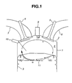
- Fig. 1 is a cross section illustrating an embodiment of an in-cylinder direct-injection spark-ignition internal combustion engine having a piston formed with a bowl-shaped piston cavity.
- Fig. 2 is a top view of the piston of the engine of the embodiment, having the improved bowl-in-piston combustion chamber structure.
- Fig. 3 is a perspective view showing the piston crown portion of the engine of the embodiment.
- Fig. 4 is a graph illustrating the relationship between an air/fuel mixture ratio (A/F) and a rate of change in indicated mean effective pressure, and showing the difference of lean misfire limit between the prior art engine and the improved engine.
-
- Referring now to the drawings, particularly to Fig. 1, the in-cylinder direct-injection spark-ignition engine of the invention is exemplified in a four-valve, gasoline-fuel, spark-ignition internal combustion engine having a pent-roof combustion chamber. As shown in Fig. 1, in the direct-injection spark-ignition engine of the embodiment, the ignition plug (the spark plug) 9 is located essentially at the center of the
combustion chamber 4. Thecylinder head 2 is mounted on acylinder block 1 having an engine cylinder. Apiston 3 is provided in the cylinder to be movable through a stroke in the cylinder. Thecombustion chamber 4 is defined by the cylinder wall of thecylinder block 1, the bottom face of thecylinder head 2, and the top surface (or the piston crown or the piston head) of thepiston 3. The engine is equipped with two intake ports (7, 7), offsetting from the center axial line of the cylinder bored in thecylinder block 1. As clearly seen in Fig. 2, thecylinder head 2 is equipped with two intake valve ports (7, 7), offsetting from the center axial line of the cylinder formed in acylinder block 1, and two exhaust valve ports (8, 8), offsetting from the center axial line of the cylinder in the opposite direction to positions of the intake ports. As appreciated from Fig. 1, the engine has a so-called cross-flow port structure. Two intake valves (5, 5) are disposed in the respective intake ports (7, 7) to open and close them, whereas two exhaust valves (6, 6) are disposed in the respective exhaust ports (8, 8) to open and close them. A fuel-injector valve 10 is provided in a side wall portion of thecombustion chamber 4 and in the vicinity of the substantially middle portion of two downstream opening ends of the intake ports (7, 7), so as to inject or spray out fuel directly into thecombustion chamber 4. Each of the intake ports (7, 7) is contoured to easily affect sufficient turbulent action, that is, a strong normal tumble flow (denoted by a in Fig. 1) to the air-fuel mixture, in the form of a vertical vortex (in-cylinder normal tumble flow) tumbling within thecombustion chamber 4. The strong normal tumble flow indicated by the arrow a in Fig. 1, is a vertical-vortex tumble flow being directed upward from the intake valve, flowing via the vicinity of thefuel injector 10 toward the piston crown, and then turned reversely along a bowl-shaped piston bowl cavity combustion chamber 11 (fully described later), and thus directed toward the vicinity of the tip of thespark plug 9. As shown in Figs. 1, 2, and 3, the bowl-shaped piston cavity combustion chamber (simply, a piston bow cavity) 11 is formed in the piston crown of thepiston 3. Thepiston bowl cavity 11 functions as a tumble-flow guide groove. Therefore, the normal tumble flow a is guided by virtue of thepiston bowl cavity 11 of thepiston 3, and thus directed to the vicinity of the tip of thespark plug 9. Structural details of thepiston bowl cavity 11 are hereunder described. - As seen from the side view in Fig. 1, the
piston bowl cavity 11 is formed into a circular-arc shape in a direction along streamlines of the normal tumble flow a of intake air. As appreciated from the cross section of thepiston 3 shown in Fig. 1, a substantially right-hand half of the piston bowl cavity closer to theexhaust valve 6 than the intake valve is formed as a moderately sloped or curved, comparatively shallow cavity portion, while a substantially left-hand half of thepiston bowl cavity 11 closer to theintake valve 5 than the exhaust valve is formed as a steeply sloped or curved, comparatively deep cavity portion. The deepest portion α of thepiston bowl cavity 11 is slightly offset from the center of the piston crown (the axis of the piston 3) toward the intake valve side. The offset between the deepest portion α and the center of the piston crown, that is, the distance of the deepest portion α from the axis of thepiston 3, is dimensioned so that the ratio of the offset to the cylinder bore is within a specified range of 5 to 20%. The depth of the deepest portion α, measured from the uppermost face of the piston crown of thepiston 3, is dimensioned so that the ratio of the depth of the deepest portion α to the cylinder bore is within a specified range of 5 to 20%. This is because an excessively shallow piston bowl structure produces a relatively weak tumbling action, and on the contrary an excessive deep piston bowl structure results in an increase in the thickness of the piston crown, that is, increased piston-head weight. As shown in Fig. 1, the moderate curved line R1, included in the moderately sloped or curved, comparatively shallow cavity portion (see the substantially right-hand half of thepiston bowl cavity 11 shown in Fig. 1), continues with the steep curved line R2, included in the steeply sloped or curved, comparatively deep cavity portion (see the substantially left-hand half of thepiston bowl cavity 11 shown in Fig. 1), on the same tangential line at the deepest portion α. The radial distance β of each of diametrically-opposing cavity ends of thepiston bowl cavity 11, in the direction along a substantially central streamline of tumble flow on thepiston bowl cavity 11, to the edged portion of the circumference of the piston crown of thepiston 3, is dimensioned so that the ratio of the radial distance β to the cylinder bore is within a specified range of 5 to 15%. The lower limit (such as 5%) of the ratio of the radial distance β to the cylinder bore is determined depending on a mechanical strength of thepiston 3. On the other hand, the upper limit (such as 15%) of the ratio of the radial distance β to the cylinder bore is determined, accounting for an optimally-controlled fling-up action of air-fuel mixture caused by the normal tumble flow a. An excessively large radial distance β (at the exhaust valve side) is a difficulty to entry of the tumble flow (turned reversely along the pent-roof side combustion chamber) into thepiston bowl cavity 11. Conversely, if the radial distance β (at the intake valve side) is excessively large, the fuel spray, injected from theinjector 10 on the compression stroke during the stratified charge combustion mode, cannot be effectively carried on the normal tumble flow a and delivered to the vicinity of the tip of thespark plug 9. For the reasons set out above, in the improved piston structure of the embodiment, the radial distance β is dimensioned so that the ratio of the radial distance β to the cylinder bore is within the specified range of 5 to 15%. Additionally, as appreciated from the top view of Fig. 2, as per a cavity width of thepiston bowl cavity 11, measured in a direction perpendicular to the direction along a substantially central streamline of normal tumble flow whose central streamline passes through the axis of the piston and extends from the exhaust-valve side to the intake-valve side, the moderately sloped or curved, comparatively shallow cavity portion of the piston bowl cavity 11 (the exhaust-valve side shallow cavity portion) is relatively wide, whereas the steeply sloped or curved, comparatively deep cavity portion of the piston bowl cavity 11 (the intake-valve side deep cavity portion) is relatively narrow. In the shown embodiment, the central cavity width γ (defined as a line segment between and including two diametrically-opposing points located on the circumferential edge of thepiston bowl cavity 11 and passing through the axis of thepiston 3 in the direction perpendicular to the direction along the substantially central streamline of tumble flow on the piston bowl cavity) is dimensioned so that the ratio of the central cavity width γ to the cylinder bore is within a specified range of 50 to 70%. As per a cross-sectional area of a cross section of thepiston bowl cavity 11, cut in an arbitrary plane perpendicular to the direction along the substantially central stream line of tumble flow on the bowl cavity, a curvature of thepiston bowl cavity 11 at each cross section, cut in the arbitrary plane, is dimensioned so that the cross-sectional area is substantially same over a specified range offsetting from the above line segment (passing the axis of the piston 3) by a predetermined distance s (or a predetermined offset s) in two opposite directions along the substantially central streamline of tumble flow on thebowl cavity 11. In the piston bowl structure of the embodiment, as seen from the top view of Fig. 2, the rightward offset s (or the leftward offset s) is dimensioned so that the ratio of the offset s to the cylinder bore is within a specified range of 5 to 20%. As previously discussed, the cavity width of the exhaust-valve side shallow cavity portion of thepiston bowl cavity 11 is relatively wide, while the cavity width of the intake-valve side deep cavity portion of thepiston bowl cavity 11 is relatively narrow. The edged portion of the circumference of the piston bowlcavity combustion chamber 11 formed in the piston crown of thepiston 3 is dimensioned so that the angle δ between opposite side edged portions of the piston bowl cavity, gradually widening from the intake valve side to the exhaust valve side or gradually narrowing in the direction along the substantially central streamline of tumble flow on thebowl cavity 11, is greater than a fuel-spray angle of the fuel spray, injected from the injector on the compression stroke during the stratified charge combustion mode. For instance, suppose that the spray angle is 50 degrees, it is preferable to set the "bowl-cavity opposite-side-edges tapering angle" δ to 60 degrees. - With the previously-discussed arrangement, during a stratified charge combustion mode (a late injection combustion mode) where late fuel-injection delays the event until near the end of the compression stroke to produce a stratified air-fuel mixture, and the flame begins in a small very rich air-fuel mixture layer around the tip of the
spark plug 9 and after ignition, spreads to the leaner mixture filling the rest of thecombustion chamber 4, the engine of the embodiment having the improved piston bowl cavity structure produces a vertical-vortex in-cylinder normal tumble flow a within thecombustion chamber 4, so that the fuel spray injected by theinjector 10 is directed or delivered to the vicinity of the tip of thespark plug 9. The normal tumble flow a is useful to avoid spray/wall impingement between fuel spray and the wall surface of thepiston ball cavity 11. Furthermore, in the engine of the embodiment, the width of thepiston bowl cavity 11, functioning as a guide groove for the normal tumble flow a, is relatively wide at the exhaust-valve side and relatively narrow at the intake-valve side. Also, the depth of thepiston bowl cavity 11 is relatively shallow at the exhaust valve side and relatively deep at the intake valve side. Therefore, as seen in Fig. 3, the piston bow cavity structure of the embodiment can smoothly and reliably carry or guide the normal tumble flow a, entering from the exhaust valve side into thepiston bowl cavity 11, toward the intake valve side (the underside of the fuel injector 10) without overflowing the tumble flow out of thebowl cavity 11. Moreover, the piston bowl cavity structure of the embodiment allows streamlines of tumble flow on thepiston bowl cavity 11 to be gradually concentrated toward within the substantially central streamline of tumble flow whose central streamline passes through the center of the piston crown of thepiston 3. This produces a strong normal tumble flow directed to a desired point. Owing to the concentrated streamlines of tumble flow properly guided and concentrated by the reasonably curved recessed inner peripheral wall surface of thepiston bowl cavity 11 having unique shape, dimensions and geometry, the engine of the embodiment can provide an effective fling-up action according to which fuel spray, injected from theinjector 10 on the compression stroke during the stratified charge combustion mode, are flung upward and reliably directed toward the tip of thespark plug 9. Thus, by virtue of the controlled strong normal tumble flow, the fuel spray can be effectively carried to the vicinity of the tip of thespark plug 9 to certainly create the richer air/fuel mixture layer around the tip of thespark plug 9 during the stratified combustion mode. This ensures a clean, stable combustion during the stratified charge combustion mode. - Referring now to Fig. 4, there is shown the result of comparison between a rate of change in indicated mean effective pressure obtained by the improved piston bowl cavity structure of the present invention and a rate of change in indicated mean effective pressure obtained by the conventional piston bowl cavity structure. The improved piston bowl cavity structure of the invention, can reduce the rate of change in indicated mean effective pressure at a low level even at an ultra-lean air/fuel mixture ratio AFR. That is to say, the combustion stability, particularly the stratified combustion stability can be remarkably enhanced, and thus effectively enlarging the lean misfire limit. Also, the controlled strong normal tumble flow a contributes to a good delivery of the fuel spray on the tumble flow to the vicinity of the tip of the
spark plug 9. Also, with the aid of the controlled strong normal tumble flow a, there is less possibility of fuel film adhered to the inner wall of thebowl cavity 11. This avoids undesired carbonization from occurring due to the fuel film, and also reduces exhaust emissions (unburned hydrocarbons, and particulate matter) and deposits in the engine, thereby improving fuel economy and thus enhancing the exhaust-emission control performance. Moreover, as previously discussed, a curvature of thepiston bowl cavity 11 at each cross section is dimensioned, so that the cross-sectional area of a cross section of thebowl cavity 11, arbitrarily cut in a plane perpendicular to the direction along the substantially central streamline of tumble flow on the bowl cavity, is substantially same over a specified range offsetting from the above line segment by a predetermined offset s in two opposite directions along the substantially central streamline of tumble flow on thebowl cavity 11. Thus, it is possible to more certainly reliably prevent the tumble flow from overflowing out of thebowl cavity 11. That is, the unique piston bowl cavity structure of the invention serves as an excellent tumble-flow guidance. Additionally, the edged portion of the circumference of the piston crown of thepiston 3 is dimensioned, so that the angle δ between opposite side edged portions of the piston bowl cavity, gradually widening in a direction along a line extending from the intake valve side to the center of the piston crown or gradually narrowing in the direction along the substantially central streamline of tumble flow on thebowl cavity 11, is greater than a fuel-spray angle . Such a relatively wide angle δ between opposite side edged portions of thepiston bowl cavity 11 is effective to certainly carry the fuel spray on the tumble flow, without spray/wall impingement between fuel spray and the wall surface of the piston crown (the piston top surface). - While the foregoing is a description of the preferred embodiments carried out the invention, it will be understood that the invention is not limited to the particular embodiments shown and described herein, but that various changes and modifications may be made.
Claims (8)
- A direct-injection spark-ignition engine operable in at least a stratified charge combustion mode where fuel injection is executed on a compression stroke while introducing a vertical-vortex tumble flow to an induced air drawn into a combustion chamber through an intake port, comprising:a cylinder block having a cylinder;a piston movable through a stroke in the cylinder, and having a piston bowl cavity combustion chamber in a piston crown;a cylinder head mounted on said cylinder block;a spark plug centrally located at a center of the combustion chamber;a fuel injector valve provided at a side wall portion of the combustion chamber and near an intake valve disposed in the intake port, for injecting fuel directly into the combustion chamber;said piston bowl cavity combustion chamber being formed in the piston crown, for producing a normal tumble flow being directed toward a vicinity of said fuel injector valve and then directed toward a vicinity of said spark plug while being guided by said piston bowl cavity combustion chamber; and a width of said piston bowl cavity combustion chamber is relatively wide at an exhaust valve side and relatively narrow at an intake valve side; and a depth of said piston bowl cavity combustion chamber is relatively shallow at the exhaust valve side and relatively deep at the intake valve side.
- The direct-injection spark-ignition engine as claimed in claim 1, wherein a curvature of said piston bowl cavity combustion chamber at each cross section, cut in an arbitrary plane perpendicular to a direction along a substantially central streamline of the normal tumble flow on said piston bowl cavity combustion chamber, is dimensioned so that the cross-sectional area of each cross section of said piston bowl cavity combustion chamber is substantially same over a specified range offsetting from a predetermined line segment by a predetermined offset in two opposite directions along the substantially central streamline of the normal tumble flow on said piston bowl cavity combustion chamber, said predetermined line segment between and including two diametrically-opposing points located on a circumferential edge of said piston bowl cavity combustion chamber and passing through an axis of said piston in the direction perpendicular to the direction along the substantially central streamline of the normal tumble flow on said piston bowl cavity combustion chamber.
- The direct-injection spark-ignition engine as claimed in claim 2, wherein said predetermined offset is dimensioned so that a ratio of the offset to a cylinder bore is within the specified range of 5 to 20%.
- The direct-injection spark-ignition engine as claimed in any one of preceding claims, wherein an edged portion of a circumference of said piston bowl cavity combustion chamber is dimensioned so that an angle between opposite side edged portions of said piston bowl cavity combustion chamber, gradually widening from the intake valve side to the exhaust valve side, is greater than a fuel-spray angle of fuel injected by said fuel injector valve.
- The direct-injection spark-ignition engine as claimed in any one of preceding claims, wherein a deepest portion of said piston bowl cavity combustion chamber is offset from a center of the piston crown of said piston toward the intake valve side.
- The direct-injection spark-ignition engine as claimed in claim 5, wherein an offset between the deepest portion and the center of the piston crown is dimensioned so that a ratio of the offset to a cylinder bore is within a specified range of 5 to 20%.
- The direct-injection spark-ignition engine as claimed in claims 6, wherein a depth of the deepest portion is dimensioned so that a ratio of the depth of the deepest portion to the cylinder bore is within a specified range of 5 to 20%.
- The direct-injection spark-ignition engine as claimed in claims 7, wherein a moderately curved, relatively shallow cavity portion of the exhaust valve side of the piston bowl cavity combustion chamber, continues with a steeply curved, relatively deep cavity portion of the intake valve side of the piston bowl cavity combustion chamber, on a same tangential line at the deepest portion, and a radial distance of each of diametrically-opposing cavity ends of said piston bowl cavity combustion chamber, in a direction along a substantially central streamline of the normal tumble flow on the piston bowl cavity combustion chamber, to an edged portion of a circumference of the piston crown, is dimensioned so that a ratio of the radial distance to a cylinder bore is within a specified range of 5 to 15%.
Applications Claiming Priority (2)
| Application Number | Priority Date | Filing Date | Title |
|---|---|---|---|
| JP15921499A JP3598880B2 (en) | 1999-06-07 | 1999-06-07 | Direct injection spark ignition type internal combustion engine |
| JP15921499 | 1999-06-07 |
Publications (3)
| Publication Number | Publication Date |
|---|---|
| EP1069291A2 EP1069291A2 (en) | 2001-01-17 |
| EP1069291A3 EP1069291A3 (en) | 2001-05-23 |
| EP1069291B1 true EP1069291B1 (en) | 2004-11-24 |
Family
ID=15688833
Family Applications (1)
| Application Number | Title | Priority Date | Filing Date |
|---|---|---|---|
| EP00111713A Expired - Lifetime EP1069291B1 (en) | 1999-06-07 | 2000-05-31 | In-cylinder direct-injection spark-ignition engine |
Country Status (3)
| Country | Link |
|---|---|
| EP (1) | EP1069291B1 (en) |
| JP (1) | JP3598880B2 (en) |
| DE (1) | DE60016099T2 (en) |
Families Citing this family (20)
| Publication number | Priority date | Publication date | Assignee | Title |
|---|---|---|---|---|
| DE19962293A1 (en) * | 1999-12-23 | 2001-06-28 | Fev Motorentech Gmbh | Piston internal combustion engine has direct fuel injection, roof-shaped cylinder ceiling and piston base in vertical section, one roof surface associated with inlet valves, one with outlet valve |
| AUPQ604000A0 (en) * | 2000-03-03 | 2000-03-30 | Orbital Engine Company (Australia) Proprietary Limited | Internal combustion engines and control |
| JP3835171B2 (en) | 2001-01-12 | 2006-10-18 | 日産自動車株式会社 | Piston of internal combustion engine |
| JP2002295260A (en) | 2001-03-30 | 2002-10-09 | Mazda Motor Corp | Spark ignition direct injection engine |
| DE10354682B4 (en) * | 2003-11-22 | 2016-05-04 | Fev Gmbh | Reciprocating internal combustion engine with direct fuel injection via an injector arranged on the inlet side |
| US7690348B2 (en) | 2005-01-06 | 2010-04-06 | Mitsubishi Jidosha Kogyo Kabushiki Kaisha | Direct-injection spark-ignition internal combustion engine |
| JP4501832B2 (en) * | 2005-09-29 | 2010-07-14 | マツダ株式会社 | Spark ignition direct injection engine |
| US8056531B2 (en) | 2010-06-24 | 2011-11-15 | Ford Global Technologies Llc | Shallow piston bowl and injector spray pattern for a gasoline, direct-injection engine |
| DE102016007279A1 (en) * | 2016-06-15 | 2017-12-21 | Audi Ag | Piston for an internal combustion engine and corresponding internal combustion engine |
| WO2018221638A1 (en) | 2017-06-02 | 2018-12-06 | マツダ株式会社 | Combustion chamber structure for engines |
| EP3617470A4 (en) | 2017-06-02 | 2020-03-04 | Mazda Motor Corporation | COMBUSTION CHAMBER STRUCTURE FOR ENGINES |
| JP6565999B2 (en) | 2017-06-02 | 2019-08-28 | マツダ株式会社 | engine |
| JP6566000B2 (en) | 2017-06-02 | 2019-08-28 | マツダ株式会社 | engine |
| FR3071879B1 (en) * | 2017-09-29 | 2022-03-11 | Ifp Energies Now | TWO-VALVE INTERNAL COMBUSTION ENGINE |
| JP7118943B2 (en) * | 2019-11-21 | 2022-08-16 | 本田技研工業株式会社 | internal combustion engine |
| JP7388224B2 (en) * | 2020-02-12 | 2023-11-29 | マツダ株式会社 | Internal combustion engine with prechamber |
| CN112112726A (en) * | 2020-09-17 | 2020-12-22 | 潍柴动力股份有限公司 | Strong tumble combustion system and engine |
| JP7585739B2 (en) * | 2020-11-25 | 2024-11-19 | マツダ株式会社 | Engine combustion chamber structure |
| EP4314529A1 (en) * | 2021-03-26 | 2024-02-07 | Jaguar Land Rover Limited | A piston for a lean-burn gasoline engine |
| EP4314530A1 (en) * | 2021-03-26 | 2024-02-07 | Jaguar Land Rover Limited | A piston for an engine |
Family Cites Families (9)
| Publication number | Priority date | Publication date | Assignee | Title |
|---|---|---|---|---|
| KR100266059B1 (en) * | 1995-03-28 | 2000-10-02 | 나까무라 히로까즈 | Internal combustion internal combustion engine |
| US5775288A (en) * | 1995-08-17 | 1998-07-07 | Yamaha Hatsudoki Kabushiki Kaisha | Combustion chamber |
| JPH09317479A (en) | 1996-05-31 | 1997-12-09 | Suzuki Motor Corp | In-cylinder injection engine |
| JPH10299486A (en) * | 1997-04-30 | 1998-11-10 | Yamaha Motor Co Ltd | In-cylinder fuel injection engine |
| FR2763646B1 (en) * | 1997-05-20 | 1999-07-02 | Renault | DIRECT INJECTION ENGINE AND CONTROLLED IGNITION |
| DE19730842A1 (en) * | 1997-07-18 | 1999-01-21 | Audi Ag | IC engine |
| JPH11159214A (en) | 1997-12-01 | 1999-06-15 | Sanshin Kinzoku Kogyo Kk | Locking device of shelf member of storage shelf for placing article |
| DE19809066A1 (en) * | 1998-03-04 | 1999-09-09 | Audi Ag | IC engine with direct fuel injection |
| DE19928108A1 (en) * | 1999-06-19 | 2000-12-28 | Daimler Chrysler Ag | Combustion engine with fuel injection device has dished recess in piston end face and angled fuel injection jet cooperating to provide tumble movement of injected fuel |
-
1999
- 1999-06-07 JP JP15921499A patent/JP3598880B2/en not_active Expired - Lifetime
-
2000
- 2000-05-31 EP EP00111713A patent/EP1069291B1/en not_active Expired - Lifetime
- 2000-05-31 DE DE60016099T patent/DE60016099T2/en not_active Expired - Lifetime
Also Published As
| Publication number | Publication date |
|---|---|
| EP1069291A2 (en) | 2001-01-17 |
| JP2000345847A (en) | 2000-12-12 |
| EP1069291A3 (en) | 2001-05-23 |
| JP3598880B2 (en) | 2004-12-08 |
| DE60016099D1 (en) | 2004-12-30 |
| DE60016099T2 (en) | 2005-12-15 |
Similar Documents
| Publication | Publication Date | Title |
|---|---|---|
| EP1069291B1 (en) | In-cylinder direct-injection spark-ignition engine | |
| EP1365123B1 (en) | Direct-injection spark-ignition engine | |
| US5927244A (en) | Combustion chamber structure having piston cavity | |
| US5720253A (en) | Direct-injection type spark-ignition internal combustion engine | |
| US7464687B2 (en) | Direct-injection engine, method of controlling the same, piston used in the same and fuel injection valve used in the same | |
| US6725649B2 (en) | Control apparatus for a direct-injection, spark-ignition engine | |
| EP1259715B1 (en) | Incylinder direct injection spark ignition engine | |
| US6173690B1 (en) | In-cylinder direct-injection spark-ignition engine | |
| JP3733721B2 (en) | Direct-injection spark ignition internal combustion engine | |
| US6269790B1 (en) | Combustion chamber for DISI engines with exhaust side piston bowl | |
| EP1111216A2 (en) | Combustion chamber for DISI engines with swirl airflows | |
| JP4258935B2 (en) | Spark ignition type reciprocating engine | |
| JP3514083B2 (en) | In-cylinder direct injection spark ignition engine | |
| GB2310003A (en) | Combustion chamber for in-cylinder direct fuel injection, spark ignition engine | |
| US6651611B2 (en) | Combustion chamber for swirl flow two valve spark ignition direct injection engine | |
| JP4316719B2 (en) | In-cylinder injection control device | |
| EP1088972B1 (en) | In-cylinder direct-injection spark-ignition engine | |
| JP4108806B2 (en) | Combustion chamber structure of in-cylinder direct injection spark ignition engine | |
| JP2501556Y2 (en) | Internal combustion engine intake system | |
| JP2936803B2 (en) | In-cylinder internal combustion engine | |
| JP3820688B2 (en) | In-cylinder direct injection spark ignition engine | |
| JP3674135B2 (en) | Direct in-cylinder spark ignition engine | |
| JPH02305319A (en) | Combustion chamber structure of engine | |
| JPS587811B2 (en) | Internal combustion engine gas injection device | |
| JP2000120467A (en) | Direct injection spark ignition type internal combustion engine |
Legal Events
| Date | Code | Title | Description |
|---|---|---|---|
| PUAI | Public reference made under article 153(3) epc to a published international application that has entered the european phase |
Free format text: ORIGINAL CODE: 0009012 |
|
| 17P | Request for examination filed |
Effective date: 20000531 |
|
| AK | Designated contracting states |
Kind code of ref document: A2 Designated state(s): DE FR GB |
|
| AX | Request for extension of the european patent |
Free format text: AL;LT;LV;MK;RO;SI |
|
| PUAL | Search report despatched |
Free format text: ORIGINAL CODE: 0009013 |
|
| AK | Designated contracting states |
Kind code of ref document: A3 Designated state(s): AT BE CH CY DE DK ES FI FR GB GR IE IT LI LU MC NL PT SE |
|
| AX | Request for extension of the european patent |
Free format text: AL;LT;LV;MK;RO;SI |
|
| AKX | Designation fees paid |
Free format text: DE FR GB |
|
| GRAP | Despatch of communication of intention to grant a patent |
Free format text: ORIGINAL CODE: EPIDOSNIGR1 |
|
| GRAS | Grant fee paid |
Free format text: ORIGINAL CODE: EPIDOSNIGR3 |
|
| GRAA | (expected) grant |
Free format text: ORIGINAL CODE: 0009210 |
|
| AK | Designated contracting states |
Kind code of ref document: B1 Designated state(s): DE FR GB |
|
| REG | Reference to a national code |
Ref country code: GB Ref legal event code: FG4D |
|
| REF | Corresponds to: |
Ref document number: 60016099 Country of ref document: DE Date of ref document: 20041230 Kind code of ref document: P |
|
| PLBE | No opposition filed within time limit |
Free format text: ORIGINAL CODE: 0009261 |
|
| STAA | Information on the status of an ep patent application or granted ep patent |
Free format text: STATUS: NO OPPOSITION FILED WITHIN TIME LIMIT |
|
| 26N | No opposition filed |
Effective date: 20050825 |
|
| ET | Fr: translation filed | ||
| REG | Reference to a national code |
Ref country code: FR Ref legal event code: PLFP Year of fee payment: 17 |
|
| REG | Reference to a national code |
Ref country code: FR Ref legal event code: PLFP Year of fee payment: 18 |
|
| REG | Reference to a national code |
Ref country code: FR Ref legal event code: PLFP Year of fee payment: 19 |
|
| PGFP | Annual fee paid to national office [announced via postgrant information from national office to epo] |
Ref country code: DE Payment date: 20190521 Year of fee payment: 20 |
|
| PGFP | Annual fee paid to national office [announced via postgrant information from national office to epo] |
Ref country code: FR Payment date: 20190410 Year of fee payment: 20 |
|
| PGFP | Annual fee paid to national office [announced via postgrant information from national office to epo] |
Ref country code: GB Payment date: 20190529 Year of fee payment: 20 |
|
| REG | Reference to a national code |
Ref country code: DE Ref legal event code: R071 Ref document number: 60016099 Country of ref document: DE |
|
| REG | Reference to a national code |
Ref country code: GB Ref legal event code: PE20 Expiry date: 20200530 |
|
| PG25 | Lapsed in a contracting state [announced via postgrant information from national office to epo] |
Ref country code: GB Free format text: LAPSE BECAUSE OF EXPIRATION OF PROTECTION Effective date: 20200530 |