EP1069291B1 - Moteur à injection directe et à allumage commandé - Google Patents
Moteur à injection directe et à allumage commandé Download PDFInfo
- Publication number
- EP1069291B1 EP1069291B1 EP00111713A EP00111713A EP1069291B1 EP 1069291 B1 EP1069291 B1 EP 1069291B1 EP 00111713 A EP00111713 A EP 00111713A EP 00111713 A EP00111713 A EP 00111713A EP 1069291 B1 EP1069291 B1 EP 1069291B1
- Authority
- EP
- European Patent Office
- Prior art keywords
- combustion chamber
- piston
- bowl cavity
- piston bowl
- tumble flow
- Prior art date
- Legal status (The legal status is an assumption and is not a legal conclusion. Google has not performed a legal analysis and makes no representation as to the accuracy of the status listed.)
- Expired - Lifetime
Links
Images


Classifications
-
- F—MECHANICAL ENGINEERING; LIGHTING; HEATING; WEAPONS; BLASTING
- F02—COMBUSTION ENGINES; HOT-GAS OR COMBUSTION-PRODUCT ENGINE PLANTS
- F02B—INTERNAL-COMBUSTION PISTON ENGINES; COMBUSTION ENGINES IN GENERAL
- F02B17/00—Engines characterised by means for effecting stratification of charge in cylinders
- F02B17/005—Engines characterised by means for effecting stratification of charge in cylinders having direct injection in the combustion chamber
-
- F—MECHANICAL ENGINEERING; LIGHTING; HEATING; WEAPONS; BLASTING
- F02—COMBUSTION ENGINES; HOT-GAS OR COMBUSTION-PRODUCT ENGINE PLANTS
- F02B—INTERNAL-COMBUSTION PISTON ENGINES; COMBUSTION ENGINES IN GENERAL
- F02B23/00—Other engines characterised by special shape or construction of combustion chambers to improve operation
- F02B23/08—Other engines characterised by special shape or construction of combustion chambers to improve operation with positive ignition
- F02B23/10—Other engines characterised by special shape or construction of combustion chambers to improve operation with positive ignition with separate admission of air and fuel into cylinder
- F02B23/104—Other engines characterised by special shape or construction of combustion chambers to improve operation with positive ignition with separate admission of air and fuel into cylinder the injector being placed on a side position of the cylinder
- F02B23/105—Other engines characterised by special shape or construction of combustion chambers to improve operation with positive ignition with separate admission of air and fuel into cylinder the injector being placed on a side position of the cylinder the fuel is sprayed directly onto or close to the spark plug
-
- F—MECHANICAL ENGINEERING; LIGHTING; HEATING; WEAPONS; BLASTING
- F02—COMBUSTION ENGINES; HOT-GAS OR COMBUSTION-PRODUCT ENGINE PLANTS
- F02B—INTERNAL-COMBUSTION PISTON ENGINES; COMBUSTION ENGINES IN GENERAL
- F02B31/00—Modifying induction systems for imparting a rotation to the charge in the cylinder
-
- F—MECHANICAL ENGINEERING; LIGHTING; HEATING; WEAPONS; BLASTING
- F02—COMBUSTION ENGINES; HOT-GAS OR COMBUSTION-PRODUCT ENGINE PLANTS
- F02B—INTERNAL-COMBUSTION PISTON ENGINES; COMBUSTION ENGINES IN GENERAL
- F02B23/00—Other engines characterised by special shape or construction of combustion chambers to improve operation
- F02B23/08—Other engines characterised by special shape or construction of combustion chambers to improve operation with positive ignition
- F02B23/10—Other engines characterised by special shape or construction of combustion chambers to improve operation with positive ignition with separate admission of air and fuel into cylinder
- F02B2023/106—Tumble flow, i.e. the axis of rotation of the main charge flow motion is horizontal
-
- F—MECHANICAL ENGINEERING; LIGHTING; HEATING; WEAPONS; BLASTING
- F02—COMBUSTION ENGINES; HOT-GAS OR COMBUSTION-PRODUCT ENGINE PLANTS
- F02B—INTERNAL-COMBUSTION PISTON ENGINES; COMBUSTION ENGINES IN GENERAL
- F02B75/00—Other engines
- F02B75/02—Engines characterised by their cycles, e.g. six-stroke
- F02B2075/022—Engines characterised by their cycles, e.g. six-stroke having less than six strokes per cycle
- F02B2075/027—Engines characterised by their cycles, e.g. six-stroke having less than six strokes per cycle four
-
- F—MECHANICAL ENGINEERING; LIGHTING; HEATING; WEAPONS; BLASTING
- F02—COMBUSTION ENGINES; HOT-GAS OR COMBUSTION-PRODUCT ENGINE PLANTS
- F02B—INTERNAL-COMBUSTION PISTON ENGINES; COMBUSTION ENGINES IN GENERAL
- F02B75/00—Other engines
- F02B75/12—Other methods of operation
- F02B2075/125—Direct injection in the combustion chamber for spark ignition engines, i.e. not in pre-combustion chamber
-
- F—MECHANICAL ENGINEERING; LIGHTING; HEATING; WEAPONS; BLASTING
- F02—COMBUSTION ENGINES; HOT-GAS OR COMBUSTION-PRODUCT ENGINE PLANTS
- F02B—INTERNAL-COMBUSTION PISTON ENGINES; COMBUSTION ENGINES IN GENERAL
- F02B2275/00—Other engines, components or details, not provided for in other groups of this subclass
- F02B2275/48—Tumble motion in gas movement in cylinder
-
- F—MECHANICAL ENGINEERING; LIGHTING; HEATING; WEAPONS; BLASTING
- F02—COMBUSTION ENGINES; HOT-GAS OR COMBUSTION-PRODUCT ENGINE PLANTS
- F02F—CYLINDERS, PISTONS OR CASINGS, FOR COMBUSTION ENGINES; ARRANGEMENTS OF SEALINGS IN COMBUSTION ENGINES
- F02F1/00—Cylinders; Cylinder heads
- F02F1/24—Cylinder heads
- F02F2001/241—Cylinder heads specially adapted to pent roof shape of the combustion chamber
-
- F—MECHANICAL ENGINEERING; LIGHTING; HEATING; WEAPONS; BLASTING
- F02—COMBUSTION ENGINES; HOT-GAS OR COMBUSTION-PRODUCT ENGINE PLANTS
- F02F—CYLINDERS, PISTONS OR CASINGS, FOR COMBUSTION ENGINES; ARRANGEMENTS OF SEALINGS IN COMBUSTION ENGINES
- F02F1/00—Cylinders; Cylinder heads
- F02F1/24—Cylinder heads
- F02F2001/244—Arrangement of valve stems in cylinder heads
- F02F2001/245—Arrangement of valve stems in cylinder heads the valve stems being orientated at an angle with the cylinder axis
-
- F—MECHANICAL ENGINEERING; LIGHTING; HEATING; WEAPONS; BLASTING
- F02—COMBUSTION ENGINES; HOT-GAS OR COMBUSTION-PRODUCT ENGINE PLANTS
- F02F—CYLINDERS, PISTONS OR CASINGS, FOR COMBUSTION ENGINES; ARRANGEMENTS OF SEALINGS IN COMBUSTION ENGINES
- F02F3/00—Pistons
- F02F3/26—Pistons having combustion chamber in piston head
-
- Y—GENERAL TAGGING OF NEW TECHNOLOGICAL DEVELOPMENTS; GENERAL TAGGING OF CROSS-SECTIONAL TECHNOLOGIES SPANNING OVER SEVERAL SECTIONS OF THE IPC; TECHNICAL SUBJECTS COVERED BY FORMER USPC CROSS-REFERENCE ART COLLECTIONS [XRACs] AND DIGESTS
- Y02—TECHNOLOGIES OR APPLICATIONS FOR MITIGATION OR ADAPTATION AGAINST CLIMATE CHANGE
- Y02T—CLIMATE CHANGE MITIGATION TECHNOLOGIES RELATED TO TRANSPORTATION
- Y02T10/00—Road transport of goods or passengers
- Y02T10/10—Internal combustion engine [ICE] based vehicles
- Y02T10/12—Improving ICE efficiencies
Definitions
- the present invention relates to the improvements of an in-cylinder direct-injection spark-ignition internal combustion engine equipped with an open combustion chamber type piston in which fuel is injected directly into engine cylinders and it is ignited by an electric spark, and specifically to techniques for effectively producing strong stable tumble flow for stable combustion (particularly, stable stratified charge combustion), and capable of improving exhaust emission.
- a combustion mode is changeable between a homogeneous combustion mode (an early injection combustion mode) where fuel-injection early in the intake stroke produces a homogeneous air-fuel mixture, and a stratified charge combustion mode (a late injection combustion mode) where late fuel-injection delays the event until near the end of the compression stroke to produce a stratified air-fuel mixture.
- stratified charging or stratified combustion mode is effective under a low engine-load operating condition where the amount of fuel injected is comparatively less.
- the direct-injection spark-ignition engine disclosed in the Japanese Patent Provisional Publication No. 9-317479 has a spark plug centrally located at a center of the combustion chamber, a fuel injector located at a side wall portion of the combustion chamber and near an intake valve disposed in an intake port, and a piston having a piston bowl cavity combustion chamber in a piston crown.
- the engine disclosed in the Japanese Patent Provisional Publication No.9-317479 is operable in a stratified charge combustion mode where fuel injection is executed on a compression stroke while introducing a reverse tumble flow to an induced air drawn into the combustion chamber through the intake port. Such a piston bowl cavity acts to promote strong tumble flow.
- the above reverse tumble flow is a vertical-vortex tumble flow being directed downward from the intake valve, flowing via the vicinity of the fuel injector toward the piston crown, then turned reversely along the piston bowl cavity, and thus directed toward the spark plug.
- the piston bowl cavity is dimensioned so that the angle between opposite side edge portions of the piston bowl cavity, gradually widening in a direction along a line extending from the intake valve side to the center of the piston crown (or in a direction along streamlines of the tumble flow along the bowl cavity), is substantially equal to a fuel-spray angle.
- the angle between opposite side edge portions of the piston bowl cavity will be hereinafter referred to as a "bowl-cavity opposite-side-edges tapering angle".
- the engine includes difficulty in concentrating the fuel spray in a desired point while the fuel is guided by the piston bowl cavity having the above-mentioned structural dimensions and geometry and carried on the reverse tumble flow.
- the fuel spray injected from the injector on the compression stroke during the stratified charge combustion mode, cannot be certainly carried on the reverse tumble flow and delivered to the vicinity of the tip of the spark plug.
- the optimally-controlled fling-up action is obtained by full cooperation of a strong in-cylinder normal tumble flow concentrating to a desired point and a relatively wide angle between opposite side edge portions of the piston bowl cavity, gradually widening in a direction along a line extending from the intake valve side to the center of the piston crown or gradually narrowing in a direction along the normal tumble-flow streamline on the bowl cavity, as compared to a fuel-spray angle.
- a direct-injection spark-ignition engine operable in at least a stratified charge combustion mode where fuel injection is executed on a compression stroke while introducing a vertical-vortex tumble flow to an induced air drawn into a combustion chamber through an intake port, comprises a cylinder block having a cylinder, a piston movable through a stroke in the cylinder and having a piston bowl cavity combustion chamber in a piston crown, a cylinder head mounted on the cylinder block, a spark plug centrally located at a center of the combustion chamber, and a fuel injector valve provided at a side wall portion of the combustion chamber and near an intake valve disposed in the intake port for injecting fuel directly into the combustion chamber.
- the piston bowl cavity combustion chamber is formed in the piston crown for producing a normal tumble flow being directed toward a vicinity of said fuel injector valve and then directed toward a vicinity of the spark plug while being guided by the piston bowl cavity combustion chamber.
- the width of the piston bowl cavity combustion chamber is relatively wide at an exhaust valve side and relatively narrow at an intake valve side.
- a depth of the piston bowl cavity combustion chamber is relatively shallow at the exhaust valve side and relatively deep at the intake valve side.
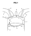
- the in-cylinder direct-injection spark-ignition engine of the invention is exemplified in a four-valve, gasoline-fuel, spark-ignition internal combustion engine having a pent-roof combustion chamber.
- the ignition plug (the spark plug) 9 is located essentially at the center of the combustion chamber 4.
- the cylinder head 2 is mounted on a cylinder block 1 having an engine cylinder.
- a piston 3 is provided in the cylinder to be movable through a stroke in the cylinder.
- the combustion chamber 4 is defined by the cylinder wall of the cylinder block 1, the bottom face of the cylinder head 2, and the top surface (or the piston crown or the piston head) of the piston 3.
- the engine is equipped with two intake ports (7, 7), offsetting from the center axial line of the cylinder bored in the cylinder block 1.
- the cylinder head 2 is equipped with two intake valve ports (7, 7), offsetting from the center axial line of the cylinder formed in a cylinder block 1, and two exhaust valve ports (8, 8), offsetting from the center axial line of the cylinder in the opposite direction to positions of the intake ports.
- the engine has a so-called cross-flow port structure.
- a fuel-injector valve 10 is provided in a side wall portion of the combustion chamber 4 and in the vicinity of the substantially middle portion of two downstream opening ends of the intake ports (7, 7), so as to inject or spray out fuel directly into the combustion chamber 4.
- Each of the intake ports (7, 7) is contoured to easily affect sufficient turbulent action, that is, a strong normal tumble flow (denoted by a in Fig. 1) to the air-fuel mixture, in the form of a vertical vortex (in-cylinder normal tumble flow) tumbling within the combustion chamber 4.
- the strong normal tumble flow indicated by the arrow a in Fig. 1 is a vertical-vortex tumble flow being directed upward from the intake valve, flowing via the vicinity of the fuel injector 10 toward the piston crown, and then turned reversely along a bowl-shaped piston bowl cavity combustion chamber 11 (fully described later), and thus directed toward the vicinity of the tip of the spark plug 9.
- the bowl-shaped piston cavity combustion chamber (simply, a piston bow cavity) 11 is formed in the piston crown of the piston 3.
- the piston bowl cavity 11 functions as a tumble-flow guide groove. Therefore, the normal tumble flow a is guided by virtue of the piston bowl cavity 11 of the piston 3, and thus directed to the vicinity of the tip of the spark plug 9. Structural details of the piston bowl cavity 11 are hereunder described.
- the piston bowl cavity 11 is formed into a circular-arc shape in a direction along streamlines of the normal tumble flow a of intake air.
- a substantially right-hand half of the piston bowl cavity closer to the exhaust valve 6 than the intake valve is formed as a moderately sloped or curved, comparatively shallow cavity portion
- a substantially left-hand half of the piston bowl cavity 11 closer to the intake valve 5 than the exhaust valve is formed as a steeply sloped or curved, comparatively deep cavity portion.
- the deepest portion ⁇ of the piston bowl cavity 11 is slightly offset from the center of the piston crown (the axis of the piston 3) toward the intake valve side.
- the offset between the deepest portion ⁇ and the center of the piston crown is dimensioned so that the ratio of the offset to the cylinder bore is within a specified range of 5 to 20%.
- the depth of the deepest portion ⁇ measured from the uppermost face of the piston crown of the piston 3, is dimensioned so that the ratio of the depth of the deepest portion ⁇ to the cylinder bore is within a specified range of 5 to 20%.
- the moderate curved line R1 included in the moderately sloped or curved, comparatively shallow cavity portion continues with the steep curved line R2, included in the steeply sloped or curved, comparatively deep cavity portion (see the substantially left-hand half of the piston bowl cavity 11 shown in Fig. 1), on the same tangential line at the deepest portion ⁇ .
- the radial distance ⁇ of each of diametrically-opposing cavity ends of the piston bowl cavity 11, in the direction along a substantially central streamline of tumble flow on the piston bowl cavity 11, to the edged portion of the circumference of the piston crown of the piston 3, is dimensioned so that the ratio of the radial distance ⁇ to the cylinder bore is within a specified range of 5 to 15%.
- the lower limit (such as 5%) of the ratio of the radial distance ⁇ to the cylinder bore is determined depending on a mechanical strength of the piston 3.
- the upper limit (such as 15%) of the ratio of the radial distance ⁇ to the cylinder bore is determined, accounting for an optimally-controlled fling-up action of air-fuel mixture caused by the normal tumble flow a.
- radial distance ⁇ is a difficulty to entry of the tumble flow (turned reversely along the pent-roof side combustion chamber) into the piston bowl cavity 11.
- the radial distance ⁇ is excessively large, the fuel spray, injected from the injector 10 on the compression stroke during the stratified charge combustion mode, cannot be effectively carried on the normal tumble flow a and delivered to the vicinity of the tip of the spark plug 9.
- the radial distance ⁇ is dimensioned so that the ratio of the radial distance ⁇ to the cylinder bore is within the specified range of 5 to 15%.
- the moderately sloped or curved, comparatively shallow cavity portion of the piston bowl cavity 11 (the exhaust-valve side shallow cavity portion) is relatively wide, whereas the steeply sloped or curved, comparatively deep cavity portion of the piston bowl cavity 11 (the intake-valve side deep cavity portion) is relatively narrow.
- the central cavity width ⁇ (defined as a line segment between and including two diametrically-opposing points located on the circumferential edge of the piston bowl cavity 11 and passing through the axis of the piston 3 in the direction perpendicular to the direction along the substantially central streamline of tumble flow on the piston bowl cavity) is dimensioned so that the ratio of the central cavity width ⁇ to the cylinder bore is within a specified range of 50 to 70%.
- a curvature of the piston bowl cavity 11 at each cross section, cut in the arbitrary plane, is dimensioned so that the cross-sectional area is substantially same over a specified range offsetting from the above line segment (passing the axis of the piston 3) by a predetermined distance s (or a predetermined offset s ) in two opposite directions along the substantially central streamline of tumble flow on the bowl cavity 11.
- the rightward offset s (or the leftward offset s ) is dimensioned so that the ratio of the offset s to the cylinder bore is within a specified range of 5 to 20%.
- the cavity width of the exhaust-valve side shallow cavity portion of the piston bowl cavity 11 is relatively wide, while the cavity width of the intake-valve side deep cavity portion of the piston bowl cavity 11 is relatively narrow.
- the edged portion of the circumference of the piston bowl cavity combustion chamber 11 formed in the piston crown of the piston 3 is dimensioned so that the angle ⁇ between opposite side edged portions of the piston bowl cavity, gradually widening from the intake valve side to the exhaust valve side or gradually narrowing in the direction along the substantially central streamline of tumble flow on the bowl cavity 11, is greater than a fuel-spray angle ⁇ of the fuel spray, injected from the injector on the compression stroke during the stratified charge combustion mode.
- the spray angle ⁇ is 50 degrees
- it is preferable to set the "bowl-cavity opposite-side-edges tapering angle" ⁇ to 60 degrees.
- the engine of the embodiment having the improved piston bowl cavity structure produces a vertical-vortex in-cylinder normal tumble flow a within the combustion chamber 4, so that the fuel spray injected by the injector 10 is directed or delivered to the vicinity of the tip of the spark plug 9.
- the normal tumble flow a is useful to avoid spray/wall impingement between fuel spray and the wall surface of the piston ball cavity 11.
- the width of the piston bowl cavity 11, functioning as a guide groove for the normal tumble flow a is relatively wide at the exhaust-valve side and relatively narrow at the intake-valve side.
- the depth of the piston bowl cavity 11 is relatively shallow at the exhaust valve side and relatively deep at the intake valve side. Therefore, as seen in Fig. 3, the piston bow cavity structure of the embodiment can smoothly and reliably carry or guide the normal tumble flow a , entering from the exhaust valve side into the piston bowl cavity 11, toward the intake valve side (the underside of the fuel injector 10) without overflowing the tumble flow out of the bowl cavity 11.
- the piston bowl cavity structure of the embodiment allows streamlines of tumble flow on the piston bowl cavity 11 to be gradually concentrated toward within the substantially central streamline of tumble flow whose central streamline passes through the center of the piston crown of the piston 3. This produces a strong normal tumble flow directed to a desired point.
- the engine of the embodiment can provide an effective fling-up action according to which fuel spray, injected from the injector 10 on the compression stroke during the stratified charge combustion mode, are flung upward and reliably directed toward the tip of the spark plug 9.
- the fuel spray can be effectively carried to the vicinity of the tip of the spark plug 9 to certainly create the richer air/fuel mixture layer around the tip of the spark plug 9 during the stratified combustion mode. This ensures a clean, stable combustion during the stratified charge combustion mode.
- Fig. 4 there is shown the result of comparison between a rate of change in indicated mean effective pressure obtained by the improved piston bowl cavity structure of the present invention and a rate of change in indicated mean effective pressure obtained by the conventional piston bowl cavity structure.
- the improved piston bowl cavity structure of the invention can reduce the rate of change in indicated mean effective pressure at a low level even at an ultra-lean air/fuel mixture ratio AFR. That is to say, the combustion stability, particularly the stratified combustion stability can be remarkably enhanced, and thus effectively enlarging the lean misfire limit. Also, the controlled strong normal tumble flow a contributes to a good delivery of the fuel spray on the tumble flow to the vicinity of the tip of the spark plug 9.
- a curvature of the piston bowl cavity 11 at each cross section is dimensioned, so that the cross-sectional area of a cross section of the bowl cavity 11, arbitrarily cut in a plane perpendicular to the direction along the substantially central streamline of tumble flow on the bowl cavity, is substantially same over a specified range offsetting from the above line segment by a predetermined offset s in two opposite directions along the substantially central streamline of tumble flow on the bowl cavity 11.
- the unique piston bowl cavity structure of the invention serves as an excellent tumble-flow guidance.
- edged portion of the circumference of the piston crown of the piston 3 is dimensioned, so that the angle ⁇ between opposite side edged portions of the piston bowl cavity, gradually widening in a direction along a line extending from the intake valve side to the center of the piston crown or gradually narrowing in the direction along the substantially central streamline of tumble flow on the bowl cavity 11, is greater than a fuel-spray angle ⁇ .
- Such a relatively wide angle ⁇ between opposite side edged portions of the piston bowl cavity 11 is effective to certainly carry the fuel spray on the tumble flow, without spray/wall impingement between fuel spray and the wall surface of the piston crown (the piston top surface).
Landscapes
- Engineering & Computer Science (AREA)
- Chemical & Material Sciences (AREA)
- Combustion & Propulsion (AREA)
- Mechanical Engineering (AREA)
- General Engineering & Computer Science (AREA)
- Combustion Methods Of Internal-Combustion Engines (AREA)
Claims (8)
- Moteur à injection directe et à allumage par étincelle fonctionnant selon au moins un mode de combustion à charge stratifiée dans lequel l'injection du carburant est exécutée lors d'une course de compression tandis que l'introduction d'un écoulement à tourbillon transversal de vortex vertical vers de l'air induit tiré dans une chambre de combustion par l'intermédiaire d'un orifice d'admission, comprenant :ladite chambre de combustion à cavité de tête de piston étant formée dans la calotte de piston pour produire un tourbillon transversal normal dirigé au voisinage de ladite soupape d'injection de carburant puis vers la proximité de ladite bougie d'allumage tout en étant guidé par ladite chambre de combustion à cavité de tête de piston, et une largeur de ladite chambre de combustion à cavité de tête de piston étant relativement grande du côté de la soupape d'échappement et relativement petite du côté de la soupape d'admission, et une profondeur de ladite chambre de combustion à cavité de tête de piston étant relativement faible du côté de la soupape d'échappement et relativement grande du côté de la soupape d'admission.un bloc cylindre possédant un cylindre;un piston mobile selon une course dans le cylindre et possédant une chambre de combustion à cavité de tête de piston dans une calotte de piston ;une culasse montée sur ledit bloc cylindre ;une bougie d'allumage placée au centre de la chambre de combustion ;une soupape d'injection de carburant prévue sur une partie de paroi latérale de la chambre de combustion et près d'une soupape d'admission placée dans l'orifice d'admission pour une injection directe du carburant dans la chambre de combustion ;
- Moteur à allumage par étincelle et injection directe selon la revendication 1, dans lequel une courbure de ladite chambre de combustion à cavité de tête de piston sur chaque section transversale, dans un plan arbitraire normal à une direction le long d'une ligne de courant sensiblement centrale de taurbillon transversal normal sur ladite chambre de combustion à cavité de tête de piston est dimensionnée de telle façon que la surface de section transversale de chaque section transversale de ladite chambre de combustion à cavité de tête de piston soit sensiblement identique sur un intervalle spécifié décalé d'un segment prédéterminé de ligne d'une valeur prédéterminée dans deux directions opposées le long de la ligne de courant sensiblement centrale de tourbillon transversal normal sur ladite chambre de combustion à cavité de tête de piston, ledit segment linéaire prédéterminé étant interposé et comprenant deux points diamétralement opposés situés sur un bord de circonférence de ladite chambre de combustion à cavité de tête de piston et traversant un axe dudit piston dans la direction normale à celle le long de la ligne de courant sensiblement centrale de tourbillon transversal normal sur ladite chambre de combustion à cavité de tête de piston.
- Moteur à allumage par étincelle et injection directe selon la revendication 2, dans lequel ledit décalage prédéterminé est dimensionné de telle façon qu'un rapport du décalage sur un alésage de cylindre soit compris de façon spécifique entre 5 et 20%.
- Moteur à allumage par étincelle et injection directe selon l'une quelconque des revendications précédentes, dans lequel une partie d'arête d'une circonférence de ladite chambre de combustion à cavité de tète de piston est dimensionnée de telle façon qu'un angle entre des parties d'arête de côté opposé de ladite chambre de combustion à cavité de tête de piston, s'élargissant progressivement du coté de la soupape d'admission vers le côté de la soupape d'échappement, soit plus grand qu'un angle de pulvérisation du carburant injecté par ladite soupape d'injection de carburant.
- Moteur à allumage par étincelle et injection directe selon l'une quelconque des revendications précédentes, dans lequel une partie la plus protonde de ladite chambre de combustion à cavité de tête de piston est décalée du centre de la calotte de piston dudit piston vers le côté de la soupape d'admission.
- Moteur à allumage par étincelle et injection directe selon la revendication 5, dans lequel un décalage entre la partie la plus profonde et le centre de la calotte de piston est dimensionné de telle façon qu'un rapport du décalage sur un alésage de cylindre soit compris dans un intervalle spécifié de 5 à 20%.
- Moteur à allumage par étincelle et injection directe selon la revendication 6, dans lequel une profondeur de la partie la plus profonde est dimensionnée de telle façon qu'un rapport de la profondeur de la partie la plus profonde sur l'alésage de cylindre soit compris dans un intervalle spécifié de 5 à 20%.
- Moteur à allumage par étincelle et injection directe selon la revendication 7, dans lequel une partie de cavité de courbure modérée et relativement peu profonde du côté de la soupape d'échappement de la chambre de combustion à cavité de tète de piston se poursuit par une partie de cavité à forte courbure et relativement profonde du côté de la soupape d'admission de la chambre de combustion à cavité de tête de piston sur une même tangente de la partie la plus profonde, et une distance radiale de chacune des extrémités diamétralement opposées de cavité de ladite chambre de combustion à cavité de tête de piston dans une direction le long d'une ligne de courant sensiblement centrale du tourbillon transversal normal sur la chambre de combustion à cavité de tête de piston, vers une partie d'arête d'une circonférence de la calotte de piston est dimensionnée de telle façon qu'un rapport de la distance radiale sur un alésage de cylindre soit compris dans un intervalle spécifié de 5 à 15%.
Applications Claiming Priority (2)
| Application Number | Priority Date | Filing Date | Title |
|---|---|---|---|
| JP15921499A JP3598880B2 (ja) | 1999-06-07 | 1999-06-07 | 直噴火花点火式内燃機関 |
| JP15921499 | 1999-06-07 |
Publications (3)
| Publication Number | Publication Date |
|---|---|
| EP1069291A2 EP1069291A2 (fr) | 2001-01-17 |
| EP1069291A3 EP1069291A3 (fr) | 2001-05-23 |
| EP1069291B1 true EP1069291B1 (fr) | 2004-11-24 |
Family
ID=15688833
Family Applications (1)
| Application Number | Title | Priority Date | Filing Date |
|---|---|---|---|
| EP00111713A Expired - Lifetime EP1069291B1 (fr) | 1999-06-07 | 2000-05-31 | Moteur à injection directe et à allumage commandé |
Country Status (3)
| Country | Link |
|---|---|
| EP (1) | EP1069291B1 (fr) |
| JP (1) | JP3598880B2 (fr) |
| DE (1) | DE60016099T2 (fr) |
Families Citing this family (20)
| Publication number | Priority date | Publication date | Assignee | Title |
|---|---|---|---|---|
| DE19962293A1 (de) * | 1999-12-23 | 2001-06-28 | Fev Motorentech Gmbh | Hubkolbenbrennkraftmaschine mit Kraftstoffdirekteinspritzung über einen einlassseitig angeordneten Injektor |
| AUPQ604000A0 (en) * | 2000-03-03 | 2000-03-30 | Orbital Engine Company (Australia) Proprietary Limited | Internal combustion engines and control |
| JP3835171B2 (ja) | 2001-01-12 | 2006-10-18 | 日産自動車株式会社 | 内燃機関のピストン |
| JP2002295260A (ja) | 2001-03-30 | 2002-10-09 | Mazda Motor Corp | 火花点火式直噴エンジン |
| DE10354682B4 (de) * | 2003-11-22 | 2016-05-04 | Fev Gmbh | Hubkolbenbrennkraftmaschine mit Kraftstoffdirekteinspritzung über einen einlaßseitig angeordneten Injektor |
| US7690348B2 (en) | 2005-01-06 | 2010-04-06 | Mitsubishi Jidosha Kogyo Kabushiki Kaisha | Direct-injection spark-ignition internal combustion engine |
| JP4501832B2 (ja) * | 2005-09-29 | 2010-07-14 | マツダ株式会社 | 火花点火式直噴エンジン |
| US8056531B2 (en) | 2010-06-24 | 2011-11-15 | Ford Global Technologies Llc | Shallow piston bowl and injector spray pattern for a gasoline, direct-injection engine |
| DE102016007279A1 (de) * | 2016-06-15 | 2017-12-21 | Audi Ag | Kolben für eine Brennkraftmaschine sowie entsprechende Brennkraftmaschine |
| WO2018221638A1 (fr) | 2017-06-02 | 2018-12-06 | マツダ株式会社 | Structure de chambre de combustion pour moteurs |
| EP3617470A4 (fr) | 2017-06-02 | 2020-03-04 | Mazda Motor Corporation | Structure de chambre de combustion destinée à des moteurs |
| JP6565999B2 (ja) | 2017-06-02 | 2019-08-28 | マツダ株式会社 | エンジン |
| JP6566000B2 (ja) | 2017-06-02 | 2019-08-28 | マツダ株式会社 | エンジン |
| FR3071879B1 (fr) * | 2017-09-29 | 2022-03-11 | Ifp Energies Now | Moteur a combustion interne a deux soupapes |
| JP7118943B2 (ja) * | 2019-11-21 | 2022-08-16 | 本田技研工業株式会社 | 内燃機関 |
| JP7388224B2 (ja) * | 2020-02-12 | 2023-11-29 | マツダ株式会社 | プレチャンバを備える内燃機関 |
| CN112112726A (zh) * | 2020-09-17 | 2020-12-22 | 潍柴动力股份有限公司 | 一种强滚流燃烧系统及发动机 |
| JP7585739B2 (ja) * | 2020-11-25 | 2024-11-19 | マツダ株式会社 | エンジンの燃焼室構造 |
| EP4314529A1 (fr) * | 2021-03-26 | 2024-02-07 | Jaguar Land Rover Limited | Piston pour moteur à essence à mélange pauvre |
| EP4314530A1 (fr) * | 2021-03-26 | 2024-02-07 | Jaguar Land Rover Limited | Piston pour un moteur |
Family Cites Families (9)
| Publication number | Priority date | Publication date | Assignee | Title |
|---|---|---|---|---|
| KR100266059B1 (ko) * | 1995-03-28 | 2000-10-02 | 나까무라 히로까즈 | 통내분사형내연기관 |
| US5775288A (en) * | 1995-08-17 | 1998-07-07 | Yamaha Hatsudoki Kabushiki Kaisha | Combustion chamber |
| JPH09317479A (ja) | 1996-05-31 | 1997-12-09 | Suzuki Motor Corp | 筒内噴射式エンジン |
| JPH10299486A (ja) * | 1997-04-30 | 1998-11-10 | Yamaha Motor Co Ltd | 筒内燃料噴射式エンジン |
| FR2763646B1 (fr) * | 1997-05-20 | 1999-07-02 | Renault | Moteur a injection directe et allumage commande |
| DE19730842A1 (de) * | 1997-07-18 | 1999-01-21 | Audi Ag | Brennkraftmaschine |
| JPH11159214A (ja) | 1997-12-01 | 1999-06-15 | Sanshin Kinzoku Kogyo Kk | 物品収納棚の物品載置棚部材用ロック装置 |
| DE19809066A1 (de) * | 1998-03-04 | 1999-09-09 | Audi Ag | Direkteinspritzende Brennkraftmaschine |
| DE19928108A1 (de) * | 1999-06-19 | 2000-12-28 | Daimler Chrysler Ag | Kolben für tumblegestützte Brennverfahren |
-
1999
- 1999-06-07 JP JP15921499A patent/JP3598880B2/ja not_active Expired - Lifetime
-
2000
- 2000-05-31 EP EP00111713A patent/EP1069291B1/fr not_active Expired - Lifetime
- 2000-05-31 DE DE60016099T patent/DE60016099T2/de not_active Expired - Lifetime
Also Published As
| Publication number | Publication date |
|---|---|
| EP1069291A2 (fr) | 2001-01-17 |
| JP2000345847A (ja) | 2000-12-12 |
| EP1069291A3 (fr) | 2001-05-23 |
| JP3598880B2 (ja) | 2004-12-08 |
| DE60016099D1 (de) | 2004-12-30 |
| DE60016099T2 (de) | 2005-12-15 |
Similar Documents
| Publication | Publication Date | Title |
|---|---|---|
| EP1069291B1 (fr) | Moteur à injection directe et à allumage commandé | |
| EP1365123B1 (fr) | Moteur à combustion interne avec allumage par étincelle et injection directe | |
| US5927244A (en) | Combustion chamber structure having piston cavity | |
| US5720253A (en) | Direct-injection type spark-ignition internal combustion engine | |
| US7464687B2 (en) | Direct-injection engine, method of controlling the same, piston used in the same and fuel injection valve used in the same | |
| US6725649B2 (en) | Control apparatus for a direct-injection, spark-ignition engine | |
| EP1259715B1 (fr) | Moteur a allumage commande a injection directe dans le cylindre | |
| US6173690B1 (en) | In-cylinder direct-injection spark-ignition engine | |
| JP3733721B2 (ja) | 直噴火花点火式内燃機関 | |
| US6269790B1 (en) | Combustion chamber for DISI engines with exhaust side piston bowl | |
| EP1111216A2 (fr) | Chambre de combustion pour moteur à allumage commandé et à injection directe avec tourbillon d'air | |
| JP4258935B2 (ja) | 火花点火式往復動型エンジン | |
| JP3514083B2 (ja) | 筒内直接噴射式火花点火エンジン | |
| GB2310003A (en) | Combustion chamber for in-cylinder direct fuel injection, spark ignition engine | |
| US6651611B2 (en) | Combustion chamber for swirl flow two valve spark ignition direct injection engine | |
| JP4316719B2 (ja) | 筒内噴射制御装置 | |
| EP1088972B1 (fr) | Moteur à combustion à injection directe et à allumage commandé | |
| JP4108806B2 (ja) | 筒内直噴式火花点火エンジンの燃焼室構造 | |
| JP2501556Y2 (ja) | 内燃機関の吸気装置 | |
| JP2936803B2 (ja) | 筒内噴射式内燃機関 | |
| JP3820688B2 (ja) | 筒内直接噴射式火花点火エンジン | |
| JP3674135B2 (ja) | 直接筒内噴射式火花点火エンジン | |
| JPH02305319A (ja) | エンジンの燃焼室構造 | |
| JPS587811B2 (ja) | 内燃機関の気体噴射装置 | |
| JP2000120467A (ja) | 直噴型火花点火式内燃機関 |
Legal Events
| Date | Code | Title | Description |
|---|---|---|---|
| PUAI | Public reference made under article 153(3) epc to a published international application that has entered the european phase |
Free format text: ORIGINAL CODE: 0009012 |
|
| 17P | Request for examination filed |
Effective date: 20000531 |
|
| AK | Designated contracting states |
Kind code of ref document: A2 Designated state(s): DE FR GB |
|
| AX | Request for extension of the european patent |
Free format text: AL;LT;LV;MK;RO;SI |
|
| PUAL | Search report despatched |
Free format text: ORIGINAL CODE: 0009013 |
|
| AK | Designated contracting states |
Kind code of ref document: A3 Designated state(s): AT BE CH CY DE DK ES FI FR GB GR IE IT LI LU MC NL PT SE |
|
| AX | Request for extension of the european patent |
Free format text: AL;LT;LV;MK;RO;SI |
|
| AKX | Designation fees paid |
Free format text: DE FR GB |
|
| GRAP | Despatch of communication of intention to grant a patent |
Free format text: ORIGINAL CODE: EPIDOSNIGR1 |
|
| GRAS | Grant fee paid |
Free format text: ORIGINAL CODE: EPIDOSNIGR3 |
|
| GRAA | (expected) grant |
Free format text: ORIGINAL CODE: 0009210 |
|
| AK | Designated contracting states |
Kind code of ref document: B1 Designated state(s): DE FR GB |
|
| REG | Reference to a national code |
Ref country code: GB Ref legal event code: FG4D |
|
| REF | Corresponds to: |
Ref document number: 60016099 Country of ref document: DE Date of ref document: 20041230 Kind code of ref document: P |
|
| PLBE | No opposition filed within time limit |
Free format text: ORIGINAL CODE: 0009261 |
|
| STAA | Information on the status of an ep patent application or granted ep patent |
Free format text: STATUS: NO OPPOSITION FILED WITHIN TIME LIMIT |
|
| 26N | No opposition filed |
Effective date: 20050825 |
|
| ET | Fr: translation filed | ||
| REG | Reference to a national code |
Ref country code: FR Ref legal event code: PLFP Year of fee payment: 17 |
|
| REG | Reference to a national code |
Ref country code: FR Ref legal event code: PLFP Year of fee payment: 18 |
|
| REG | Reference to a national code |
Ref country code: FR Ref legal event code: PLFP Year of fee payment: 19 |
|
| PGFP | Annual fee paid to national office [announced via postgrant information from national office to epo] |
Ref country code: DE Payment date: 20190521 Year of fee payment: 20 |
|
| PGFP | Annual fee paid to national office [announced via postgrant information from national office to epo] |
Ref country code: FR Payment date: 20190410 Year of fee payment: 20 |
|
| PGFP | Annual fee paid to national office [announced via postgrant information from national office to epo] |
Ref country code: GB Payment date: 20190529 Year of fee payment: 20 |
|
| REG | Reference to a national code |
Ref country code: DE Ref legal event code: R071 Ref document number: 60016099 Country of ref document: DE |
|
| REG | Reference to a national code |
Ref country code: GB Ref legal event code: PE20 Expiry date: 20200530 |
|
| PG25 | Lapsed in a contracting state [announced via postgrant information from national office to epo] |
Ref country code: GB Free format text: LAPSE BECAUSE OF EXPIRATION OF PROTECTION Effective date: 20200530 |