EP1775414B1 - Geteilter Winkelendstab - Google Patents
Geteilter Winkelendstab Download PDFInfo
- Publication number
- EP1775414B1 EP1775414B1 EP06020669.5A EP06020669A EP1775414B1 EP 1775414 B1 EP1775414 B1 EP 1775414B1 EP 06020669 A EP06020669 A EP 06020669A EP 1775414 B1 EP1775414 B1 EP 1775414B1
- Authority
- EP
- European Patent Office
- Prior art keywords
- profile
- end rod
- section
- projection
- stop
- Prior art date
- Legal status (The legal status is an assumption and is not a legal conclusion. Google has not performed a legal analysis and makes no representation as to the accuracy of the status listed.)
- Active
Links
Images
Classifications
-
- E—FIXED CONSTRUCTIONS
- E06—DOORS, WINDOWS, SHUTTERS, OR ROLLER BLINDS IN GENERAL; LADDERS
- E06B—FIXED OR MOVABLE CLOSURES FOR OPENINGS IN BUILDINGS, VEHICLES, FENCES OR LIKE ENCLOSURES IN GENERAL, e.g. DOORS, WINDOWS, BLINDS, GATES
- E06B9/00—Screening or protective devices for wall or similar openings, with or without operating or securing mechanisms; Closures of similar construction
- E06B9/02—Shutters, movable grilles, or other safety closing devices, e.g. against burglary
- E06B9/08—Roll-type closures
- E06B9/11—Roller shutters
- E06B9/17—Parts or details of roller shutters, e.g. suspension devices, shutter boxes, wicket doors, ventilation openings
- E06B9/17046—Bottom bars
-
- E—FIXED CONSTRUCTIONS
- E06—DOORS, WINDOWS, SHUTTERS, OR ROLLER BLINDS IN GENERAL; LADDERS
- E06B—FIXED OR MOVABLE CLOSURES FOR OPENINGS IN BUILDINGS, VEHICLES, FENCES OR LIKE ENCLOSURES IN GENERAL, e.g. DOORS, WINDOWS, BLINDS, GATES
- E06B9/00—Screening or protective devices for wall or similar openings, with or without operating or securing mechanisms; Closures of similar construction
- E06B9/02—Shutters, movable grilles, or other safety closing devices, e.g. against burglary
- E06B9/08—Roll-type closures
- E06B9/11—Roller shutters
- E06B9/17—Parts or details of roller shutters, e.g. suspension devices, shutter boxes, wicket doors, ventilation openings
- E06B9/17076—Sealing or antirattling arrangements
- E06B2009/17084—Sealing or antirattling arrangements closing outlet slot of shutter box
Definitions
- the invention relates to an angle end bar for a roller shutter curtain according to the preamble of claim 1.
- a T-shaped stop bar which can be latched into a recess of a base body of a roller shutter end strip.
- the recess is undercut at the top and bottom and has behind the upper undercut on a pocket that extends so far up that the stop bar can first be inserted into the top of the recess and as far as it can be moved upwards, that it can be pushed past the lower undercut and then lowered into the lower, undercut pocket.
- projections are provided on the side opposite the respective undercut side of Endstabprofils, so that the stop bar is clamped in each case between the undercut and the associated projection.
- the bag having body or Endstabprofil consists of a material that has a high compliance, so that the T-shaped stop bar initially under expansion of the upper, undercut pocket under a Angle can be inserted into the recess and then with further expansion of the upper undercut can be moved up until it can be pushed under bending load on the lower undercut at this.
- conventional roller shutter rods and roller blind end rods are made of materials such as PVC or aluminum, which are either very difficult to deform so far or easily break or apply permanent deformations when applying such bending moments, so that both in terms of manufacturing tolerances and the selection of materials as well the sensitivity of the fitter high demands must be made.
- roller shutter end bar with an angle stop is the German Patent DE 19749412 C1 refer to. Also there, a stop is inserted through a side wall opening of the roller shutter end bar and hooked with its end in an inner body in the roller blind end bar profile. In order to catch the stop in the roller shutter end rod, however, the inserted into the profile of the roller shutter end rod and fastened there, elastic inner body is necessary, whereby the in the DE 19749412 C1 proposed roller shutter angle end bar receives a complex and weighty structure.
- the shows DE 38 13 348 A1 a two-part Rolladenendstab, on the underside of an undercut recess is provided for a hammerhead-like projection of the end strip serving as a stop. So that the projection of the end strip can be inserted into the recess, the two parts of the roller shutter end bar are connected via a hinge joint and can thus be unfolded to release the recess. Thereafter, one part is folded back to the other and locked on a latch.
- this structure is relatively expensive.
- document DE 297 13 278 U1 shows a profiled bar for the lower end of a roller shutter, on which a stop bar can be held positively as a stop means.
- the Rolladenendstab has two identical shape stop legs that engage each with an approximately semi-circular hinge profile in an approximately same shape joint socket inside the end bar.
- the stop legs can be pivoted between their horizontal home position and a vertical position.
- a Winkelendstab is proposed with a Endstabprofil and a removable stop profile, which is characterized in that provided below an upper side undercut 9.wandaus predominantlyung Endstabprofils in which an upper projection of a support portion of the stop profile, another connection of the support portion on the outside of Endstabprofils is.
- the support portion according to the invention has a subsequent to the upper projection, applied to the side wall abutment portion and in turn adjoining the lower projection and thus surrounds a part of Endstabprofils multi-sided.
- a latching connection is advantageous, for example, via a locking groove on the support section and a complementary locking projection on the Enstabprofil or by individual locking pins and associated undercut locking pin receptacles.
- the Endstabprofil may have a vertical connection surface in the region of its lower end.
- the support section is clamped onto the end bar profile. The support portion is then held by a clamping bias, which is generated by a force acting between the upper projection and the lower projection clamping force, when the stop profile correspondingly tight against the Endstabprofil.
- the projections at least partially made of rubber-elastic material, so that on the elasticity of the rubber and its adhesion to the Endstabprofil a secure attachment of the stop profile is made.
- the rubber-elastic material is formed as a rubber profile and is located in a portion of the lower projection, which adjoins the underside of the contact surface subsequent side wall portion of Endstabprofils.
- the rubber profile with a corresponding design, can simultaneously form an end seal for the roller shutter curtain, which is usually provided on a roller shutter end bar.
- a rubber profile is part of the invention.
- the support section of the stop profile has a lower projection, which consists at least in sections of elastomeric material, in particular a rubber profile.
- the latching connection can then be provided at this section, so that the latching connection can be easily engaged due to the rubber-elastic material properties.
- the latching connection is formed on the side of the stop profile in the rubber profile, for example in the form of a latching groove, a corresponding latching projection may be provided on the side wall portion of the end bar profile adjoining the contact surface on the underside.
- the rubber profile can be designed so that it also serves as Abdichtgummi or final seal for the roller shutter curtain, so that no separate sealing lips or the like must be attached to the underside of the Winkelendstabs invention.
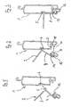
- the Endstabprofil is generally designated 1 and the stop profile with 2, wherein the stop profile has a stop portion 3 which projects at right angles from a support portion 4.
- the support section 4 in this case has an upper projection 5, which, as in Fig. 1 indicated by arrow, is inserted into a designated, undercut 9.wandaus Principleung 6 Endstabprofil. Subsequently, the stop profile 2, as indicated by arrow in Fig. 2 indicated, pivoted to Endstabprofil 1 out, so that finally the in Fig. 3 shown final state is reached.
- an abutment section, designated 8, of the carrier section 4 rests on a side wall of the end bar profile 1.
- the Endstabprofil contrasts, a Eckaus predominantlyung, which is bounded by a horizontal contact surface 7 and a vertical connection surface 11.
- a lower projection 12, 13 is provided, which is received in the assembled state of the Winkelendstabs in the Eckaus supraung.
- the lower projection 12, 13 has a portion 13 which forms an undercut groove in which a rubber profile 12 is inserted with its T-shaped projection 14.
- the rubber profile 12 has, on the one hand, a downwardly projecting sealing lip and thus forms a roller shutter closing seal on the underside of the roller shutter curtain.
- the sealing rubber profile 12 has a latching groove 9, which is associated with a latching projection 10 on the underside of the contact surface 7 adjacent side wall portion 11 so that the swung stop profile 2 can be latched to the Endstabprofil 1 and so secured despite easy installation, against loss and exchangeable with the Endstabprofil is connectable.
- the sealing rubber profile 12 could be connected to the stop profile 2 instead of the tongue and groove connection via an adhesive connection.
- connection of stop profile and Endstabprofil is additionally supported by the fact that between the upper projection 5 and the undercut groove forming portion 13 a clamping force is applied to the Endstabprofil and additionally a locking connection between the hinged to the stop profile rubber profile and the Endstabprofil is provided.
- the rubber profile 12 or its position on the stop profile 2 could also be designed such that a clamping force is applied to the end bar profile via the rubber profile and the upper projection 5.
Landscapes
- Engineering & Computer Science (AREA)
- Structural Engineering (AREA)
- Architecture (AREA)
- Civil Engineering (AREA)
- Operating, Guiding And Securing Of Roll- Type Closing Members (AREA)
Description
- Die Erfindung betrifft einen Winkelendstab für einen Rollladenbehang gemäß dem Oberbegriff des Anspruchs 1.
- Bei Winkelendstäben herkömmlicher Rolllädenbehänge sind rechtwinklig zur Rollladenbehangoberfläche nach außen ragende Anschläge vorgesehen, die verhindern sollen, dass der Rollladenendstab durch den Schlitz im Rollladenkasten durchgezogen werden kann, so dass ein vollständiges Aufwickeln des Rollladenbehangs vermieden wird.
- Da der Anschlag somit erst nach Zusammenbau des Rollladenkastens und Einbau der Wickelwelle an dem Endstab angebracht werden kann, bzw. bei fest eingebauten Rollladenkästen erst bei der Endmontage des Rollladenkastens an der abzuschottenden Gebäudeöffnung, ist es wünschenswert, den Winkelendstab möglichst montagefreundlich zu gestalten.
- Dazu ist aus der
DE 3511473 A1 ein Rollladenendstab bekannt, der eine Dichtung aufweist, die über hammerkopfartige Ansätze in hinterschnittene Rücksprünge an dem Endstab eingeschoben werden kann. Dies gelingt jedoch nur, wenn seitlich des Rollladenbehangs ein genügend großer Montageraum vorhanden ist. - Um eine Montage des Anschlags an dem Endstab von der Frontseite des Rollladenbehangs aus zu ermöglichen, ist daher schon ein Rollladen-Winkelendstab vorgeschlagen worden, bei dem der Anschlag in den Endstab eingeklipst wird.
- So zeigt die
DE 3730624 A1 eine T-förmige Anschlagleiste, die in eine Aussparung eines Grundkörpers einer Rollladenendleiste einrastbar ist. Die Aussparung ist dabei oben und unten hinterschnitten und weist hinter der oberen Hinterschneidung eine Tasche auf, die sich soweit nach oben erstreckt, dass die Anschlagleiste zunächst oben in die Aussparung eingeführt werden kann und soweit nach oben verschiebbar ist, dass sie an der unteren Hinterschneidung vorbei gedrückt werden kann und dann in die untere, hinterschnittene Tasche abgesenkt werden kann. Dabei sind auf der der jeweiligen Hinterschneidung gegenüberliegenden Seite des Endstabprofils Vorsprünge vorgesehen, so dass die Anschlagleiste jeweils zwischen die Hinterschneidung und den zugeordneten Vorsprung eingeklemmt ist. - Für die Montage des Winkelendstabs dieser Bauart ist es jedoch Voraussetzung, dass der die Tasche aufweisende Grundkörper bzw. das Endstabprofil aus einem Material besteht, das eine hohe Nachgiebigkeit hat, so dass die T-förmige Anschlagleiste zunächst unter Aufweitung der oberen, hinterschnittenen Tasche unter einem Winkel in die Aussparung eingesteckt werden kann und dann unter weiterer Aufweitung der oberen Hinterschneidung nach oben verschoben werden kann, bis sie unter Biegelast auf die untere Hinterschneidung an dieser vorbeigedrückt werden kann. Herkömmliche Rollladenstäbe und Rollladenendstäbe werden jedoch aus Materialien wie beispielsweise PVC oder Aluminium hergestellt, die sich entweder nur sehr schwer so weit verformen lassen oder bei Aufbringung derartiger Biegemomente leicht brechen bzw. bleibende Verformungen annehmen, so dass sowohl bezüglich der Fertigungstoleranzen und der Materialauswahl als auch bezüglich der Feinfühligkeit des Monteurs hohe Anforderungen gestellt werden müssen.
- Ein weiterer bekannter Rollladenendstab mit einem Winkelanschlag ist der Deutschen Patentschrift
DE 19749412 C1 zu entnehmen. Auch dort ist ein Anschlag durch eine Seitenwandöffnung des Rollladenendstabs gesteckt und mit seinem Ende in einem Innenkörper in dem Rollladenendstabprofil verhakt. Um den Anschlag in dem Rollladenendstab zu verhaken, ist jedoch der in das Profil des Rollladenendstabs eingelegte und dort befestigte, elastische Innenkörper nötig, wodurch der in derDE 19749412 C1 vorgeschlagene Rollladenwinkelendstab einen aufwendigen und gewichtigen Aufbau erhält. - Ferner zeigt die
DE 38 13 348 A1 einen zweiteiligen Rolladenendstab, an dessen Unterseite eine hinterschnittene Ausnehmung für einen hammerkopfartigen Vorsprung der als Anschlag dienenden Abschlussleiste vorgesehen ist. Damit der Vorsprung der Abschlussleiste in die Ausnehmung eingeschoben werden kann, sind die beiden Teile des Rolladenendstabs über ein Scharniergelenk verbunden und können somit auseinander geklappt werden, um die Ausnehmung freizugeben. Danach wird der eine Teil wieder zum anderen hingeklappt und über eine Rastnase verrastet. Dieser Aufbau ist jedoch relativ aufwändig. - Dokument
DE 297 13 278 U1 zeigt einen Profilstab für das untere Ende eines Rollladens, an welchem eine Anschlagleiste als Anschlagmittel formschlüssig gehalten werden kann. - Schließlich zeigt auch Dokument
DE 199 13 472 A1 einen als Anschlag und zum Verschluss einer Austrittsöffnung dienenden Rolladenendstab. Der Rolladenendstab besitzt zwei formengleiche Anschlagschenkel, die jeweils mit einem etwa halbkreisförmigen Gelenkprofil in eine etwa formengleiche Gelenkpfanne innerhalb des Endstabs eingreifen. Die Anschlagschenkel können zwischen ihrer horizontalen Grundstellung und einer vertikalen Stellung verschwenkt werden. - Hiervon ausgehend ist es Aufgabe der vorliegenden Erfindung, einen Winkelendstab für einen Rollladen zu schaffen, der stabil, einfach zu montieren und zu fertigen sowie leichtgewichtig ist.
- Diese Aufgabe wird mit den Merkmalen des Anspruchs 1 gelöst.
- Erfindungsgemäß wird ein Winkelendstab mit einem Endstabprofil und einem abnehmbaren Anschlagprofil vorgeschlagen, das sich dadurch auszeichnet, dass unterhalb einer oberseitig hinterschnittene Seitenwandausnehmung des Endstabprofils, in die ein oberer Vorsprung eines Trägerabschnitts des Anschlagprofils eingehängt ist, eine weitere Verbindung des Trägerabschnitts auf der Außenseite des Endstabprofils vorgesehen ist.
- Der Trägerabschnitt weist erfindungsgemäß einen an den oberen Vorsprung anschließenden, an der Seitenwand anliegenden Anlageabschnitt und einen wiederum daran anschließenden unteren Vorsprung auf und umgreift somit einen Teil des Endstabprofils mehrseitig.
- Mit diesem Aufbau des Winkelendstabs gelingt einerseits eine leichte Montage, denn das Anschlagprofil muss lediglich mit seinem oberen Vorsprung in die Seitenwandausnehmung eingesteckt und in die Endstellung verschwenkt werden, was schon durch sein Eigengewicht unterstützt wird. Dadurch, dass die weitere Verbindung auf der Außenseite des Endstabprofils vorgesehen ist kann dagegen ein Verbiegen von Bauteilen oder ein schwierig zu bewerkstelligendes Einführen des Unterendes des Trägerabschnitts des Anschlagprofils unterbleiben. Es ist nicht nötig, das Endstabprofil bei der Montage stark zu verformen bzw. es werden keine größeren Biegebelastungen auf das Endstabprofil ausgeübt, so dass das Endstabprofil aus einem starren Material wie beispielsweise Aluminium oder einem brüchigen Material wie beispielsweise Polymer-Kunststoff hergestellt werden kann.
- Als weitere Verbindung ist dabei eine Rastverbindung vorteilhaft, beispielsweise über eine Rastnut am Trägerabschnitt und einen komplementären Rastvorsprung am Enstabprofil oder durch einzelne Rastzapfen und zugeordnete hinterschnittene Rastzapfenaufnahmen.
- Weiterhin wäre es denkbar, als weitere Verbindung eine stoffschlüssige Verbindung vorzusehen, beispielsweise über einen auf dem Trägerabschnitt vorgesehenen Klebestreifen, mit dem das Anschlagsprofil an dem Endstabprofil angeklebt wird. Dazu kann das Endstabprofil im Bereich seines Unterendes eine vertikale Verbindungsfläche aufweisen. Dabei besteht eine weitere Alternative oder Ergänzung darin, dass der Trägerabschnitt auf das Endstabprofil aufgeklemmt ist. Der Trägerabschnitt wird dann durch eine Klemmvorspannung gehalten, welche durch eine zwischen dem oberen Vorsprung und dem unteren Vorsprung wirkende Klemmkraft erzeugt wird, wenn das Anschlagprofil entsprechend eng an dem Endstabprofil anliegt.
- Vorteilhaft ist es dabei, wenn zumindest einer der Vorsprünge zumindest abschnittsweise aus gummielastischem Material besteht, so dass über die Elastizität des Gummis und dessen Haftung an dem Endstabprofil eine sichere Befestigung des Anschlagprofils hergestellt wird. Vorzugsweise ist das gummielastische Material dabei als Gummiprofil ausgeformt und befindet sich in einem Abschnitt des unteren Vorsprungs, der dem unterseitig an die Anlagefläche anschliessenden Seitenwandabschnitt des Endstabprofils anschliesst. Dabei kann das Gummiprofil bei entsprechender Gestaltung gleichzeitig eine Abschlussdichtung für den Rollladenbehang bilden, welche an einem Rollladenendstab üblicherweise vorgesehen ist. Ein derartiges Gummiprofil ist Teil der Erfindung.
- Auch bei der vorstehend genannten bevorzugten Ausführungsform mit einer Rastverbindung ist es vorteilhaft, wenn der Trägerabschnitt des Anschlagprofils einen unteren Vorsprung aufweist, der zumindest abschnittsweise aus gummielastischem Material besteht, insbesondere aus einem Gummiprofil. Die Rastverbindung kann dann an diesem Abschnitt vorgesehen sein, so dass sich die Rastverbindung aufgrund der gummielastischen Materialeigenschaften einfach Einrasten lässt. Wenn die Rastverbindung auf seiten des Anschlagprofils im Gummiprofil ausgebildet ist, beispielsweise in Form einer Rastnut, kann ein entsprechender Rastvorsprung an dem unterseitig an die Anlagefläche anschliessenden Seitenwandabschnitt des Endstabprofils vorgesehen sein.
- Ein besonderer Vorteil ergibt sich dabei dadurch, dass das Gummiprofil so gestaltet werden kann, dass es gleichzeitig als Abdichtgummi bzw. Abschlussdichtung für den Rollladenbehang dient, so dass keine separaten Dichtlippen oder dergleichen mehr an der Unterseite des erfindungsgemäßen Winkelendstabs angebracht werden müssen.
- Die Merkmale der Ansprüche lassen sich, soweit es sinnvoll erscheint, beliebig kombinieren.
- Nachfolgend wird eine bevorzugte Ausführungsform der Erfindung anhand der Figuren erläutert. Es zeigen:
- Figur 1
- eine schematisierte Schnittansicht durch ein Endstabprofil und ein Anschlagprofil gemäß einer bevorzugten Ausführungsform der Erfindung in einer Montageanfangsstellung;
- Figur 2
- das Endstabprofil und das Anschlagprofil der
Fig. 1 in einer Montagezwischenstellung; und - Figur 3
- der aus dem Endstabprofil und dem Anschlagprofil der vorhergehenden Figuren zusammengefügte Winkelendstab nach Abschluss der Montage.
- Die Figuren zeigen die Montageabfolge beim Zusammenbau eines Winkelendstabs. Dabei ist das Endstabprofil generell mit 1 bezeichnet und das Anschlagprofil mit 2, wobei das Anschlagprofil einen Anschlagabschnitt 3 aufweist, der unter rechtem Winkel von einem Trägerabschnitt 4 absteht.
- Der Trägerabschnitt 4 weist dabei einen oberen Vorsprung 5 auf, der, wie in
Fig. 1 mit Pfeil angedeutet, in eine dafür vorgesehene, hinterschnittene Seitenwandausnehmung 6 am Endstabprofil eingesteckt wird. Anschließend wird das Anschlagprofil 2, wie durch Pfeil inFig. 2 angedeutet, zum Endstabprofil 1 hin verschwenkt, so dass schließlich der inFig. 3 dargestellte Endzustand erreicht wird. Dabei liegt ein mit 8 bezeichneter Anlageabschnitt des Trägerabschnitts 4 an einer Seitenwand des Endstabprofils 1 an. - Unterseitig weist das Endstabprofil dagegen eine Eckausnehmung auf, die von einer horizontalen Anlagefläche 7 und einer vertikalen Verbindungsfläche 11 begrenzt wird. An dem Trägerabschnitt 4 ist dagegen ein unterer Vorsprung 12, 13 vorgesehen, der in zusammengebautem Zustand des Winkelendstabs in der Eckausnehmung aufgenommen ist. Dabei hat der untere Vorsprung 12, 13 einen Abschnitt 13, der eine hinterschnittene Nut bildet, in der ein Gummiprofil 12 mit seinem T-förmigen Vorsprung 14 eingeschoben ist.
- Das Gummiprofil 12 weist einerseits eine nach unten überstehende Dichtlippe auf und bildet so eine Rollladenabschlussdichtung an der Unterseite des Rollladenbehangs. Andererseits weist das Dichtgummiprofil 12 eine Rastnut 9 auf, der ein Rastvorsprung 10 an dem unterseitig an die Anlagefläche 7 anschliessenden Seitenwandabschnitt 11 zugeordnet ist, so dass das eingeschwenkte Anschlagsprofil 2 mit dem Endstabprofil 1 verrastet werden kann und so trotz einfacher Montage fest, gegen Verlust gesichert und austauschbar mit dem Endstabprofil verbindbar ist.
- Selbstverständlich sind Abweichungen von der gezeigten Ausführungsform möglich, ohne den Rahmen der Erfindung zu verlassen, wie er in den Ansprüchen definiert ist.
- So wäre es beispielsweise denkbar, anstatt der Rastverbindung 9, 10, einen Klebestreifen an der dem Seitenwandabschnitt 11 zugewandten Wandabschnitt des Dichtgummiprofils 12 und/oder an dem Seitenwandabschnitt 11 vorzusehen. Auch könnte das Dichtgummiprofil 12 mit dem Anschlagprofil 2 anstatt über die Nut/Feder-Verbindung über eine Klebeverbindung verbunden sein.
- Weiterhin wäre es denkbar, dass die Verbindung von Anschlagprofil und Endstabprofil zusätzlich dadurch unterstützt wird, dass zwischen dem oberen Vorsprung 5 und dem die hinterschnittene Nut bildenden Abschnitt 13 eine Klemmkraft auf das Endstabprofil aufgebracht wird und zusätzlich eine Rastverbindung zwischen dem an dem Anschlagprofil eingehängten Gummiprofil und dem Endstabprofil vorgesehen ist. Anstatt dessen könnte das Gummiprofil 12 bzw. dessen Lage an dem Anschlagprofil 2 auch so gestaltet sein, dass über das Gummiprofil und den oberen Vorsprung 5 eine Klemmkraft auf das Endstabprofil aufgebracht wird.
Claims (9)
- Winkelendstab für einen Rollladenbehang, mit einem Endstabprofil (1) und einem abnehmbaren Anschlagprofil (2), das einen Anschlagabschnitt (3) zur Begrenzung des Aufwickelns des Rollladenbehangs und einen mit dem Endstabprofil (1) verbundenen Trägerabschnitt (4) aufweist, wobei das Endstabprofil (1) eine oberseitig hinterschnittene Seitenwandausnehmung (6) und der Trägerabschnitt (4) einen in die Seitenwandausnehmung (6) einhängbaren, oberen Vorsprung (5) aufweisen, so dass das Anschlagprofil (2) bei der Montage zur Erreichung seiner Endstellung lediglich mit seinem oberen Vorsprung (5) in die Seitenwandausnehmung (6) eingesteckt und in die Endstellung verschwenkt werden muss, was schon durch sein Eigengewicht unterstützt wird, dadurch gekennzeichnet, dass unterhalb der Seitenwandausnehmung (6) eine weitere Verbindung des Trägerabschnitts (4) auf der Außenseite des Endstabprofils (1) vorgesehen ist und der Trägerabschnitt (4) einen an den oberen Vorsprung (5) anschließenden, an einer Seitenwand des Endstabprofils (1) anliegenden Anlageabschnitt (8) und einen wiederum daran anschließenden unteren Vorsprung (12, 13) aufweist und somit einen Teil des Endstabprofils (1) mehrseitig umgreift.
- Winkelendstab nach Anspruch 1, dadurch gekennzeichnet, dass die weitere Verbindung eine Rastverbindung (9, 10) ist, deren einer Rastabschnitt (10) an einer vertikalen Verbindungsfläche (11) des Endstabprofils (1) vorgesehen ist und deren anderer Rastabschnitt an einem zugeordneten Verbindungsflächenabschnitt des Trägerabschnitts (4) vorgesehen ist.
- Winkelendstab nach Anspruch 1 oder 2, dadurch gekennzeichnet, dass der Trägerabschnitt (4) einen unteren Vorsprung (12, 13) aufweist, an dem der Verbindungsflächenabschnitt ausgebildet ist und die Verbindungsfläche (11) ein unterseitig an einen Querwandabschnitt (7) anschließender Seitenwandabschnitt (11) ist.
- Winkelendstab nach einem der Ansprüche 1 bis 3, dadurch gekennzeichnet, dass das Endstabprofil (1) im Bereich seines Unterendes eine horizontale Anlagefläche (7) aufweist und der Trägerabschnitt (4) einen zumindest abschnittsweise an der Anlagefläche (7) anliegenden, unteren Vorsprung (12, 13), so dass ein Klemmdruck zwischen oberem und unterem Vorsprung (5, 12, 13) auf das Endstabprofil (1) aufgebracht wird.
- Winkelendstab nach Anspruch 3 oder 4, dadurch gekennzeichnet, dass der untere Vorsprung (12, 13) zumindest abschnittsweise aus gummielastischem Material (12) besteht, vorzugsweise aus als Gummiprofil (12) ausgeformtem gummielastischem Material.
- Winkelendstab nach Anspruch 5, dadurch gekennzeichnet, dass das Gummiprofil (12) über einen rückseitigen, T-förmigen Vorsprung (14) in einer zugeordneten, hinterschnittenen Nut (13) am Anschlag eingehängt ist.
- Winkelendstab nach Anspruch 5 oder 6, dadurch gekennzeichnet, dass an dem Gummiprofil eine Rastnut (9) vorgesehen ist und an der Verbindungsfläche (11) ein zugeordneter Rastvorsprung (10).
- Endstabprofil (1) geeignet für einen Winkelendstab nach einem der vorhergehenden Ansprüche mit einer oberseitig hinterschnittenen Seitenwandausnehmung (6) zum Einhängen eines oberen Vorsprungs (5) eines Anschlagsprofils (2), wobei unterhalb der Seitenwandausnehmung (6) zur Herstellung einer weiteren Verbindung des Anschlagsprofils (2) auf der Außenseite eine Eckausnehmung vorgesehen ist, die von einer horizontalen Anlagefläche (7) und einer vertikalen Verbindungsfläche (11) begrenzt ist.
- Anschlagprofil (2) geeignet für einen Winkelendstab nach einem der Ansprüche 1 bis 7 mit einem Anschlagabschnitt (3) und einem mit einem oberen Vorsprung (5) zum Einhängen in eine Seitenwandausnehmung (6) eines Endstabprofils (1), einem an den oberen Vorsprung (5) anschließenden Anlageabschnitt (8) und einem wiederum daran anschließenden unteren Vorsprung (12, 13) zum weiteren Verbinden mit einer Außenseite des Endstabprofils (1) versehenen Trägerabschnitt (4).
Applications Claiming Priority (1)
| Application Number | Priority Date | Filing Date | Title |
|---|---|---|---|
| DE200510049330 DE102005049330B3 (de) | 2005-10-12 | 2005-10-12 | geteilter Winkelendstab |
Publications (3)
| Publication Number | Publication Date |
|---|---|
| EP1775414A2 EP1775414A2 (de) | 2007-04-18 |
| EP1775414A3 EP1775414A3 (de) | 2009-01-21 |
| EP1775414B1 true EP1775414B1 (de) | 2015-08-19 |
Family
ID=37680722
Family Applications (1)
| Application Number | Title | Priority Date | Filing Date |
|---|---|---|---|
| EP06020669.5A Active EP1775414B1 (de) | 2005-10-12 | 2006-09-30 | Geteilter Winkelendstab |
Country Status (2)
| Country | Link |
|---|---|
| EP (1) | EP1775414B1 (de) |
| DE (1) | DE102005049330B3 (de) |
Cited By (1)
| Publication number | Priority date | Publication date | Assignee | Title |
|---|---|---|---|---|
| DE102016115460A1 (de) * | 2016-08-19 | 2018-02-22 | Bernd Beck | Endleiste für Rollläden |
Families Citing this family (1)
| Publication number | Priority date | Publication date | Assignee | Title |
|---|---|---|---|---|
| DE102018110539A1 (de) * | 2018-05-03 | 2019-11-07 | Schaeffler Technologies AG & Co. KG | Halteelement zum Befestigen eines Aktors an einem Träger |
Family Cites Families (6)
| Publication number | Priority date | Publication date | Assignee | Title |
|---|---|---|---|---|
| DE3511473A1 (de) * | 1985-03-29 | 1986-10-09 | Armin 4630 Bochum Besler | Rolladen-endstab mit den auslassschlitz im rolladenkasten abdichtender dichtung |
| DE3730624A1 (de) * | 1987-09-11 | 1989-03-30 | Koemmerling Kunststoff | Rolladenendleiste |
| DE3813348A1 (de) * | 1988-04-21 | 1989-11-09 | Hans Ziegler | Rolladenendstab |
| DE29713278U1 (de) * | 1997-07-25 | 1997-09-18 | Alukon F. Grashei KG, 95176 Konradsreuth | Profilstab |
| DE19749412C1 (de) * | 1997-11-07 | 1999-04-01 | Koemmerling Kunststoff | Dichtsystem für den Rolladenkasten eines Fensters oder einer Tür |
| DE19913472A1 (de) * | 1999-03-25 | 2000-09-28 | Werner Dubiel | Rolladen-Endstab |
-
2005
- 2005-10-12 DE DE200510049330 patent/DE102005049330B3/de not_active Expired - Fee Related
-
2006
- 2006-09-30 EP EP06020669.5A patent/EP1775414B1/de active Active
Cited By (2)
| Publication number | Priority date | Publication date | Assignee | Title |
|---|---|---|---|---|
| DE102016115460A1 (de) * | 2016-08-19 | 2018-02-22 | Bernd Beck | Endleiste für Rollläden |
| DE102016115460B4 (de) * | 2016-08-19 | 2021-03-11 | Bernd Beck | Endleiste für einen Rollladen |
Also Published As
| Publication number | Publication date |
|---|---|
| EP1775414A2 (de) | 2007-04-18 |
| DE102005049330B3 (de) | 2007-03-22 |
| EP1775414A3 (de) | 2009-01-21 |
Similar Documents
| Publication | Publication Date | Title |
|---|---|---|
| DE29702516U1 (de) | Rolladenkasten für ein Fenster oder eine Türe | |
| DE102005057778A1 (de) | Putzabschlussleiste für eine Putzschicht auf einer Wärmedämmung | |
| EP2025822A2 (de) | Rahmenkonstruktion | |
| DE202007014393U1 (de) | Glasleiste zum Fixieren einer Glasscheibe in einem Fenster- oder Türrahmen | |
| DE102005049330B3 (de) | geteilter Winkelendstab | |
| DE202008018499U1 (de) | Türsystem und Türdichtung | |
| DE9305774U1 (de) | Fensterbank | |
| DE69404247T2 (de) | Rolladenkasten | |
| DE8712982U1 (de) | Rolladen oder Rolltor | |
| DE29903324U1 (de) | Rahmen eines Fensters, einer Klappe oder einer Tür an Wohnwagen, Wohnmobilen oder sonstigen Fahrzeugen | |
| EP1927715A2 (de) | Profil für Fenster- oder Türflügel | |
| EP4719797A1 (de) | Dichtungsprofil und anordnung des dichtungsprofils zwischen einer brüstung und einer fensterscheibe im dichtungsfreien design | |
| EP3680438B1 (de) | Anordnung aus einem rahmenprofil und einem dichtprofil für einen fenster- oder türrahmen | |
| EP2947225B1 (de) | Bausatz mit einem abstützelement zur montagehilfe bei einem flügelrahmen eines wohndachfenster sowie verfahren zum einhängen und/oder aushängen eines flügelrahmens | |
| DE19708061B4 (de) | Scharnier für eine Blechschranktür | |
| DE202018100888U1 (de) | Rahmensystem für einen Insekten- oder Pollenschutz einer Gebäudeöffnung | |
| DE102014103650A1 (de) | Verfahren sowie Profilsystem zur Herstellung von Gebäudefenstern, Gebäudetüren | |
| EP3770373A1 (de) | Montageeinheit und verfahren zur montage eines kastens zur aufnahme eines rollladens oder eines sonnenschutzes an einem blendrahmen | |
| EP1336718B1 (de) | Insektenschutzgitter für ein Fenster oder eine Tür | |
| EP3216970B1 (de) | Wickelwellenkasten einer gebäudeöffnungsverschattungsvorrichtung und verbindungsanordnung dafür | |
| DE202017100292U1 (de) | Insekten- oder Pollenschutzsystem | |
| DE102005037926B4 (de) | Fensteranordnung für mobile Räume und Nachrüstsatz dafür | |
| DE4424408C2 (de) | Tür | |
| DE102016120371A1 (de) | Verglasungsdichtung aus elastischem Kunststoff | |
| DE202005011088U1 (de) | Insektenschutzvorrichtung |
Legal Events
| Date | Code | Title | Description |
|---|---|---|---|
| PUAI | Public reference made under article 153(3) epc to a published international application that has entered the european phase |
Free format text: ORIGINAL CODE: 0009012 |
|
| AK | Designated contracting states |
Kind code of ref document: A2 Designated state(s): AT BE BG CH CY CZ DE DK EE ES FI FR GB GR HU IE IS IT LI LT LU LV MC NL PL PT RO SE SI SK TR |
|
| AX | Request for extension of the european patent |
Extension state: AL BA HR MK YU |
|
| PUAL | Search report despatched |
Free format text: ORIGINAL CODE: 0009013 |
|
| AK | Designated contracting states |
Kind code of ref document: A3 Designated state(s): AT BE BG CH CY CZ DE DK EE ES FI FR GB GR HU IE IS IT LI LT LU LV MC NL PL PT RO SE SI SK TR |
|
| AX | Request for extension of the european patent |
Extension state: AL BA HR MK RS |
|
| 17P | Request for examination filed |
Effective date: 20090327 |
|
| AKX | Designation fees paid |
Designated state(s): AT BE BG CH CY CZ DE DK EE ES FI FR GB GR HU IE IS IT LI LT LU LV MC NL PL PT RO SE SI SK TR |
|
| RAP1 | Party data changed (applicant data changed or rights of an application transferred) |
Owner name: ROMA KG |
|
| 17Q | First examination report despatched |
Effective date: 20111123 |
|
| GRAP | Despatch of communication of intention to grant a patent |
Free format text: ORIGINAL CODE: EPIDOSNIGR1 |
|
| INTG | Intention to grant announced |
Effective date: 20150527 |
|
| GRAS | Grant fee paid |
Free format text: ORIGINAL CODE: EPIDOSNIGR3 |
|
| GRAA | (expected) grant |
Free format text: ORIGINAL CODE: 0009210 |
|
| AK | Designated contracting states |
Kind code of ref document: B1 Designated state(s): AT BE BG CH CY CZ DE DK EE ES FI FR GB GR HU IE IS IT LI LT LU LV MC NL PL PT RO SE SI SK TR |
|
| REG | Reference to a national code |
Ref country code: GB Ref legal event code: FG4D Free format text: NOT ENGLISH |
|
| REG | Reference to a national code |
Ref country code: CH Ref legal event code: EP |
|
| REG | Reference to a national code |
Ref country code: IE Ref legal event code: FG4D Free format text: LANGUAGE OF EP DOCUMENT: GERMAN |
|
| REG | Reference to a national code |
Ref country code: AT Ref legal event code: REF Ref document number: 743968 Country of ref document: AT Kind code of ref document: T Effective date: 20150915 |
|
| REG | Reference to a national code |
Ref country code: DE Ref legal event code: R096 Ref document number: 502006014489 Country of ref document: DE |
|
| REG | Reference to a national code |
Ref country code: FR Ref legal event code: PLFP Year of fee payment: 10 |
|
| REG | Reference to a national code |
Ref country code: LT Ref legal event code: MG4D |
|
| REG | Reference to a national code |
Ref country code: NL Ref legal event code: MP Effective date: 20150819 |
|
| PG25 | Lapsed in a contracting state [announced via postgrant information from national office to epo] |
Ref country code: FI Free format text: LAPSE BECAUSE OF FAILURE TO SUBMIT A TRANSLATION OF THE DESCRIPTION OR TO PAY THE FEE WITHIN THE PRESCRIBED TIME-LIMIT Effective date: 20150819 Ref country code: GR Free format text: LAPSE BECAUSE OF FAILURE TO SUBMIT A TRANSLATION OF THE DESCRIPTION OR TO PAY THE FEE WITHIN THE PRESCRIBED TIME-LIMIT Effective date: 20151120 Ref country code: LV Free format text: LAPSE BECAUSE OF FAILURE TO SUBMIT A TRANSLATION OF THE DESCRIPTION OR TO PAY THE FEE WITHIN THE PRESCRIBED TIME-LIMIT Effective date: 20150819 Ref country code: LT Free format text: LAPSE BECAUSE OF FAILURE TO SUBMIT A TRANSLATION OF THE DESCRIPTION OR TO PAY THE FEE WITHIN THE PRESCRIBED TIME-LIMIT Effective date: 20150819 |
|
| PG25 | Lapsed in a contracting state [announced via postgrant information from national office to epo] |
Ref country code: PL Free format text: LAPSE BECAUSE OF FAILURE TO SUBMIT A TRANSLATION OF THE DESCRIPTION OR TO PAY THE FEE WITHIN THE PRESCRIBED TIME-LIMIT Effective date: 20150819 Ref country code: PT Free format text: LAPSE BECAUSE OF FAILURE TO SUBMIT A TRANSLATION OF THE DESCRIPTION OR TO PAY THE FEE WITHIN THE PRESCRIBED TIME-LIMIT Effective date: 20151221 Ref country code: ES Free format text: LAPSE BECAUSE OF FAILURE TO SUBMIT A TRANSLATION OF THE DESCRIPTION OR TO PAY THE FEE WITHIN THE PRESCRIBED TIME-LIMIT Effective date: 20150819 Ref country code: SE Free format text: LAPSE BECAUSE OF FAILURE TO SUBMIT A TRANSLATION OF THE DESCRIPTION OR TO PAY THE FEE WITHIN THE PRESCRIBED TIME-LIMIT Effective date: 20150819 Ref country code: IS Free format text: LAPSE BECAUSE OF FAILURE TO SUBMIT A TRANSLATION OF THE DESCRIPTION OR TO PAY THE FEE WITHIN THE PRESCRIBED TIME-LIMIT Effective date: 20151219 |
|
| PG25 | Lapsed in a contracting state [announced via postgrant information from national office to epo] |
Ref country code: NL Free format text: LAPSE BECAUSE OF FAILURE TO SUBMIT A TRANSLATION OF THE DESCRIPTION OR TO PAY THE FEE WITHIN THE PRESCRIBED TIME-LIMIT Effective date: 20150819 |
|
| PG25 | Lapsed in a contracting state [announced via postgrant information from national office to epo] |
Ref country code: DK Free format text: LAPSE BECAUSE OF FAILURE TO SUBMIT A TRANSLATION OF THE DESCRIPTION OR TO PAY THE FEE WITHIN THE PRESCRIBED TIME-LIMIT Effective date: 20150819 Ref country code: SK Free format text: LAPSE BECAUSE OF FAILURE TO SUBMIT A TRANSLATION OF THE DESCRIPTION OR TO PAY THE FEE WITHIN THE PRESCRIBED TIME-LIMIT Effective date: 20150819 Ref country code: CZ Free format text: LAPSE BECAUSE OF FAILURE TO SUBMIT A TRANSLATION OF THE DESCRIPTION OR TO PAY THE FEE WITHIN THE PRESCRIBED TIME-LIMIT Effective date: 20150819 Ref country code: EE Free format text: LAPSE BECAUSE OF FAILURE TO SUBMIT A TRANSLATION OF THE DESCRIPTION OR TO PAY THE FEE WITHIN THE PRESCRIBED TIME-LIMIT Effective date: 20150819 Ref country code: IT Free format text: LAPSE BECAUSE OF FAILURE TO SUBMIT A TRANSLATION OF THE DESCRIPTION OR TO PAY THE FEE WITHIN THE PRESCRIBED TIME-LIMIT Effective date: 20150819 |
|
| REG | Reference to a national code |
Ref country code: CH Ref legal event code: PL |
|
| REG | Reference to a national code |
Ref country code: DE Ref legal event code: R097 Ref document number: 502006014489 Country of ref document: DE |
|
| PG25 | Lapsed in a contracting state [announced via postgrant information from national office to epo] |
Ref country code: MC Free format text: LAPSE BECAUSE OF FAILURE TO SUBMIT A TRANSLATION OF THE DESCRIPTION OR TO PAY THE FEE WITHIN THE PRESCRIBED TIME-LIMIT Effective date: 20150819 Ref country code: RO Free format text: LAPSE BECAUSE OF FAILURE TO SUBMIT A TRANSLATION OF THE DESCRIPTION OR TO PAY THE FEE WITHIN THE PRESCRIBED TIME-LIMIT Effective date: 20150819 |
|
| PLBE | No opposition filed within time limit |
Free format text: ORIGINAL CODE: 0009261 |
|
| STAA | Information on the status of an ep patent application or granted ep patent |
Free format text: STATUS: NO OPPOSITION FILED WITHIN TIME LIMIT |
|
| REG | Reference to a national code |
Ref country code: IE Ref legal event code: MM4A |
|
| 26N | No opposition filed |
Effective date: 20160520 |
|
| GBPC | Gb: european patent ceased through non-payment of renewal fee |
Effective date: 20151119 |
|
| PG25 | Lapsed in a contracting state [announced via postgrant information from national office to epo] |
Ref country code: CH Free format text: LAPSE BECAUSE OF NON-PAYMENT OF DUE FEES Effective date: 20150930 Ref country code: IE Free format text: LAPSE BECAUSE OF NON-PAYMENT OF DUE FEES Effective date: 20150930 Ref country code: LI Free format text: LAPSE BECAUSE OF NON-PAYMENT OF DUE FEES Effective date: 20150930 |
|
| PG25 | Lapsed in a contracting state [announced via postgrant information from national office to epo] |
Ref country code: SI Free format text: LAPSE BECAUSE OF FAILURE TO SUBMIT A TRANSLATION OF THE DESCRIPTION OR TO PAY THE FEE WITHIN THE PRESCRIBED TIME-LIMIT Effective date: 20150819 |
|
| REG | Reference to a national code |
Ref country code: FR Ref legal event code: PLFP Year of fee payment: 11 |
|
| PG25 | Lapsed in a contracting state [announced via postgrant information from national office to epo] |
Ref country code: GB Free format text: LAPSE BECAUSE OF NON-PAYMENT OF DUE FEES Effective date: 20151119 |
|
| PG25 | Lapsed in a contracting state [announced via postgrant information from national office to epo] |
Ref country code: BG Free format text: LAPSE BECAUSE OF FAILURE TO SUBMIT A TRANSLATION OF THE DESCRIPTION OR TO PAY THE FEE WITHIN THE PRESCRIBED TIME-LIMIT Effective date: 20150819 Ref country code: HU Free format text: LAPSE BECAUSE OF FAILURE TO SUBMIT A TRANSLATION OF THE DESCRIPTION OR TO PAY THE FEE WITHIN THE PRESCRIBED TIME-LIMIT; INVALID AB INITIO Effective date: 20060930 |
|
| PG25 | Lapsed in a contracting state [announced via postgrant information from national office to epo] |
Ref country code: CY Free format text: LAPSE BECAUSE OF FAILURE TO SUBMIT A TRANSLATION OF THE DESCRIPTION OR TO PAY THE FEE WITHIN THE PRESCRIBED TIME-LIMIT Effective date: 20150819 |
|
| PG25 | Lapsed in a contracting state [announced via postgrant information from national office to epo] |
Ref country code: BE Free format text: LAPSE BECAUSE OF NON-PAYMENT OF DUE FEES Effective date: 20150930 |
|
| PG25 | Lapsed in a contracting state [announced via postgrant information from national office to epo] |
Ref country code: TR Free format text: LAPSE BECAUSE OF FAILURE TO SUBMIT A TRANSLATION OF THE DESCRIPTION OR TO PAY THE FEE WITHIN THE PRESCRIBED TIME-LIMIT Effective date: 20150819 |
|
| REG | Reference to a national code |
Ref country code: FR Ref legal event code: PLFP Year of fee payment: 12 |
|
| PG25 | Lapsed in a contracting state [announced via postgrant information from national office to epo] |
Ref country code: LU Free format text: LAPSE BECAUSE OF NON-PAYMENT OF DUE FEES Effective date: 20150930 |
|
| REG | Reference to a national code |
Ref country code: FR Ref legal event code: PLFP Year of fee payment: 13 |
|
| PGFP | Annual fee paid to national office [announced via postgrant information from national office to epo] |
Ref country code: FR Payment date: 20190924 Year of fee payment: 14 |
|
| PGFP | Annual fee paid to national office [announced via postgrant information from national office to epo] |
Ref country code: AT Payment date: 20190918 Year of fee payment: 14 |
|
| REG | Reference to a national code |
Ref country code: AT Ref legal event code: MM01 Ref document number: 743968 Country of ref document: AT Kind code of ref document: T Effective date: 20200930 |
|
| PG25 | Lapsed in a contracting state [announced via postgrant information from national office to epo] |
Ref country code: FR Free format text: LAPSE BECAUSE OF NON-PAYMENT OF DUE FEES Effective date: 20200930 |
|
| PG25 | Lapsed in a contracting state [announced via postgrant information from national office to epo] |
Ref country code: AT Free format text: LAPSE BECAUSE OF NON-PAYMENT OF DUE FEES Effective date: 20200930 |
|
| REG | Reference to a national code |
Ref country code: DE Ref legal event code: R084 Ref document number: 502006014489 Country of ref document: DE |
|
| PGFP | Annual fee paid to national office [announced via postgrant information from national office to epo] |
Ref country code: DE Payment date: 20250930 Year of fee payment: 20 |