EP1765703B1 - Vorrichtung zum vereinzeln von plattenförmigen gegenständen, insbesondere batterieplatten - Google Patents
Vorrichtung zum vereinzeln von plattenförmigen gegenständen, insbesondere batterieplatten Download PDFInfo
- Publication number
- EP1765703B1 EP1765703B1 EP05752467A EP05752467A EP1765703B1 EP 1765703 B1 EP1765703 B1 EP 1765703B1 EP 05752467 A EP05752467 A EP 05752467A EP 05752467 A EP05752467 A EP 05752467A EP 1765703 B1 EP1765703 B1 EP 1765703B1
- Authority
- EP
- European Patent Office
- Prior art keywords
- plate
- conveyor belt
- plates
- conveyor
- vacuum
- Prior art date
- Legal status (The legal status is an assumption and is not a legal conclusion. Google has not performed a legal analysis and makes no representation as to the accuracy of the status listed.)
- Expired - Lifetime
Links
Images





Classifications
-
- B—PERFORMING OPERATIONS; TRANSPORTING
- B65—CONVEYING; PACKING; STORING; HANDLING THIN OR FILAMENTARY MATERIAL
- B65H—HANDLING THIN OR FILAMENTARY MATERIAL, e.g. SHEETS, WEBS, CABLES
- B65H3/00—Separating articles from piles
- B65H3/08—Separating articles from piles using pneumatic force
-
- B—PERFORMING OPERATIONS; TRANSPORTING
- B65—CONVEYING; PACKING; STORING; HANDLING THIN OR FILAMENTARY MATERIAL
- B65H—HANDLING THIN OR FILAMENTARY MATERIAL, e.g. SHEETS, WEBS, CABLES
- B65H3/00—Separating articles from piles
- B65H3/08—Separating articles from piles using pneumatic force
- B65H3/0808—Suction grippers
- B65H3/0816—Suction grippers separating from the top of pile
-
- B—PERFORMING OPERATIONS; TRANSPORTING
- B65—CONVEYING; PACKING; STORING; HANDLING THIN OR FILAMENTARY MATERIAL
- B65H—HANDLING THIN OR FILAMENTARY MATERIAL, e.g. SHEETS, WEBS, CABLES
- B65H3/00—Separating articles from piles
- B65H3/46—Supplementary devices or measures to assist separation or prevent double feed
- B65H3/50—Elements, e.g. fingers, plates, rollers, inserted or traversed between articles to be separated and remainder of the pile
-
- B—PERFORMING OPERATIONS; TRANSPORTING
- B65—CONVEYING; PACKING; STORING; HANDLING THIN OR FILAMENTARY MATERIAL
- B65H—HANDLING THIN OR FILAMENTARY MATERIAL, e.g. SHEETS, WEBS, CABLES
- B65H5/00—Feeding articles separated from piles; Feeding articles to machines
- B65H5/02—Feeding articles separated from piles; Feeding articles to machines by belts or chains, e.g. between belts or chains
-
- B—PERFORMING OPERATIONS; TRANSPORTING
- B65—CONVEYING; PACKING; STORING; HANDLING THIN OR FILAMENTARY MATERIAL
- B65H—HANDLING THIN OR FILAMENTARY MATERIAL, e.g. SHEETS, WEBS, CABLES
- B65H5/00—Feeding articles separated from piles; Feeding articles to machines
- B65H5/02—Feeding articles separated from piles; Feeding articles to machines by belts or chains, e.g. between belts or chains
- B65H5/028—Feeding articles separated from piles; Feeding articles to machines by belts or chains, e.g. between belts or chains by chains
-
- B—PERFORMING OPERATIONS; TRANSPORTING
- B65—CONVEYING; PACKING; STORING; HANDLING THIN OR FILAMENTARY MATERIAL
- B65H—HANDLING THIN OR FILAMENTARY MATERIAL, e.g. SHEETS, WEBS, CABLES
- B65H5/00—Feeding articles separated from piles; Feeding articles to machines
- B65H5/22—Feeding articles separated from piles; Feeding articles to machines by air-blast or suction device
-
- B—PERFORMING OPERATIONS; TRANSPORTING
- B65—CONVEYING; PACKING; STORING; HANDLING THIN OR FILAMENTARY MATERIAL
- B65H—HANDLING THIN OR FILAMENTARY MATERIAL, e.g. SHEETS, WEBS, CABLES
- B65H5/00—Feeding articles separated from piles; Feeding articles to machines
- B65H5/22—Feeding articles separated from piles; Feeding articles to machines by air-blast or suction device
- B65H5/222—Feeding articles separated from piles; Feeding articles to machines by air-blast or suction device by suction devices
- B65H5/224—Feeding articles separated from piles; Feeding articles to machines by air-blast or suction device by suction devices by suction belts
-
- B—PERFORMING OPERATIONS; TRANSPORTING
- B65—CONVEYING; PACKING; STORING; HANDLING THIN OR FILAMENTARY MATERIAL
- B65H—HANDLING THIN OR FILAMENTARY MATERIAL, e.g. SHEETS, WEBS, CABLES
- B65H2406/00—Means using fluid
- B65H2406/30—Suction means
- B65H2406/32—Suction belts
- B65H2406/323—Overhead suction belt, i.e. holding material against gravity
-
- B—PERFORMING OPERATIONS; TRANSPORTING
- B65—CONVEYING; PACKING; STORING; HANDLING THIN OR FILAMENTARY MATERIAL
- B65H—HANDLING THIN OR FILAMENTARY MATERIAL, e.g. SHEETS, WEBS, CABLES
- B65H2406/00—Means using fluid
- B65H2406/30—Suction means
- B65H2406/34—Suction grippers
- B65H2406/342—Suction grippers being reciprocated in a rectilinear path
Definitions
- the invention relates to a device having the features of the introductory part of claim 1, as known from DE-A-3202087 is known.
- the battery plates are arranged in substantially vertical stacks, in which the plates are oriented substantially horizontally, and are taken from below from the stack. This is problematic because of the weight of the stack on the bottom plate in each case, since it happens that the battery plates adhere to one another and can not easily be removed individually.
- Exemplary is on the EP 0 141 806 B , the EP 0 608 678 A and the AT 405 824 B directed.
- the plates to be separated are fed substantially vertically standing in horizontally aligned stacks of a separating device with a gripper, which removes plates individually from the stack.
- a gripper which removes plates individually from the stack.
- a disadvantage of these known devices is that they are limited in terms of their performance because of the complicated movements of the removal gripper, which should remove the bursts individually from horizontal stacks.
- a vertical stack is processed from the top, wherein the lifting of plates from the stack an upward movement is performed.
- an endless conveyor belt is provided with it acted upon by vacuum suction cups.
- This conveyor transports removed plates (individually) to another conveyor, with which individual plates are transported away.
- the one deflection roller of the conveyor belt with the suction heads, namely the deflection roller, which is arranged in the region of the stack, is mounted in a slide up and down. From this prior art, the invention is based.
- the US 4,516,762 A deals with a device for picking up and removing individual bags from a stack, which bags are to be fed to a bag filling machine. Bag stacks are conveyed on a conveyor and positioned below the bag picking device. In addition to the conveyor for stacks of bags, a second conveyor for individual bags is provided. For lifting individual bags, a device equipped with suction heads is provided, which is movable only up and down. When a bag has been lifted off the stack, fingers are inserted from both sides under the lifted bag, and then the bag is moved laterally over the conveyor and deposited on a conveyor by a slidable device which carries the fingers.
- a sheet feeder is described in which are provided on a reciprocally movable carrier separating suction and at least one row of Schleppsaugern on a reciprocable carrier. Any matches with the subject of the application are not recognizable.
- the US 4, 439, 097 A deals with a device intended to introduce dividers between magazine bundles.
- the separator sheets are picked up by a gripper and placed on a conveyor, which inserts these between layers of magazine bundles.
- the invention is based on the object, a device of the above specify the type mentioned, with which when removing plates, in particular (lead) plates for batteries and accumulators, from stacking shorter cycle times are possible.
- the device according to the invention is suitable for the separation of battery or accumulator plates conveyed in stacks, the separated plates then being able to be supplied for further processing, for example for brushing the contact lugs, and devices for pocketing battery or accumulator plates.
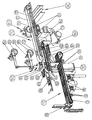
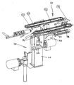
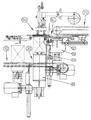
- Fig. 1 schematizes a device according to the invention in an oblique view
- Fig. 2 the device off Fig. 1 with symbolized stacks or packets of (battery) plates
- Fig. 3 a detail of the device in the area of the conveyor belt for conveying stacks
- Fig. 4 in an oblique view
- Fig. 5 the detail of the device according to Fig. 4 with stacks of (battery) plates arranged in it
- Fig. 6 the detail of the device Fig.
- FIG. 7 another detail of the device Fig. 1 in the region of a vacuum belt arranged after the separating device
- Fig. 8 another detail of the device Fig. 1 in the field of separation of plates from stacks
- Fig. 9.1 the detail Fig. 8 in side view
- Fig. 9.2 the detail Fig. 8 and 9 in side view in another working position
- the Fig. 10.1 and 10.2 in side view lifting tables in different positions.
- a device according to the invention as in Fig. 1 and 2 is shown has a conveyor belt 10 for conveying stacks of plates, in particular positive and / or negative (lead) plates for batteries and accumulators, and a subsequent to this conveyor belt 10 (Stapelerbringerband) arranged device 30 for lifting stacks to one Separation station 50 with a plate 51 and a device 58 for separating plates.
- a suction conveyor belt 70 vacuum belt
- the plates separated in the separating station 50 and deposited on an intermediate conveyor 60 are fed to a main conveyor track 90.
- the stack conveyor belt 10 is, for example, a belt or chain conveyor 11 with in the exemplary embodiment three conveying elements 12 (belts or chains), on whose in the region of in Fig. 1 lying left ends of the upper strands of the conveying elements 12, which in Fig. 1 move to the right, from any device 13 stack 14 ( Fig. 2 ) are mounted by plates.
- the upper runs of the conveying elements 12 of the stack conveyor belt 10 are associated with two lifting devices 15, which can lift off on the feeder belt 10 stack 14 of the conveyor elements 12 to stop the stack 14, so that these ordered and spaced from each other to the lifting device 30, the on Abgabeschen end of the stack conveyor belt 10 is arranged, can be supplied.
- the lifting device 30 (see. Fig. 10.1 and 10.2 ) has two independently operable lifting tables 31 and 32, of which a 31 in its lower starting position in the lower region, that is arranged substantially at the height of the upper strands of the conveying elements 12 of the Stapelzubringerbandes 10.
- This lower lifting table 31 has in the exemplary embodiment two fingers 33, which engage in the lower end position between the conveying elements 12 (chains, belts or belts) of the Stapelzubringerbandes 10.
- the second lifting table 32 is arranged in the upper area of the lifting device 30.
- On the upper lifting table 32 at least one forward and obviouslyschiebbares in the hoistway sword 34 is provided - preferably three swords 34 are provided which can engage between the fingers 33 of the lower lifting table 31 - to take over a partially processed stack 14 from the lower lifting table 31 ,
- stacks 14 can be lifted in the lifting device 30 from the lower lifting table 31 until the uppermost plate is arranged in the removal position. If a part of the plates has been removed from the stack 14, so this has been partially processed, the swords 34 of the upper lifting table 32 are advanced and hold the partially processed stack 14, so that the lower lifting table 31 can be lowered and the now smaller stack 14 is taken from the upper lifting table 32 and can be further increased by this lifting table 32 gradually.
- the singulator station 50 has a plate feeder 51, which lifts by means of suction heads 52, which are subjected to negative pressure via the housing 53 of the plate feeder 51, which receives each top plate of a stack, and on the conveying elements 61 ("wing group") as Intermediate conveyor serving wing conveyor belt 60 stores.
- the vertical movements of the plate feeder 51 are controlled by a lever link 54 and cam 55 or cam, so that this as long as needed, namely until the next set of wings 61 of the wing conveyor belt 60 has been moved to the position for the acquisition of a plate from the slicer 51, remains raised.
- the delivery point so the location in the plates are placed individually on an opposite pair of groups of wings 61 serving as intermediate conveyor wing conveyor belt 60 is located in the area of the Plattenlegers 51 so that it needs to perform only vertical movements when he a plate from the stack 14 and then deposits on a pair of wing groups 61 of the wing conveyor 60.
- the plate 51 has a housing 53 with a plurality, in the embodiment four, suction cups 52, which can be acted upon by negative pressure.
- a cam-controlled valve (rod 56, control disc 57) is provided, which introduces "false air" into the housing 53 of the plate-restorer 51 so that the plate held by the latter is a pair of wing groups 61 of the wing conveyor belt 60, namely the pair, which is just below the plate 51, drops.
- the separating station 50 is assigned a device for plate separation 58.
- This plate separation 58 has a forward and obviouslyschiebbaren finger 65, and arranged at a distance equal to the plate thickness under the finger 65 plate 66, which is also pushed back and forth (see. Fig. 9.1, 9.2) ,
- a stack 14 is raised either from the lower lift table 31 or from the upper lift table 32 so far that the uppermost plate rests against the advanced finger 65 of the plate separation 58 from below. Once this is done, the plate 66 is advanced and penetrates into the gap between the uppermost and the next lower plate, so that the upper plate is securely separated from the plate underneath and lifted off the plate 51 by means of its suction cups 52 and on the wing conveyor belt 60 can be stored.
- the wing conveyor belt 60 has two circulating about two pulleys with vertical axes endless chains 62, of which at a distance from each other support wings 61 for plates ("groups of wings") from the endless chains 62 in the space between the endless chains 62 projecting, are provided.
- each wing group 61 are provided at their rear end in the direction of travel stop bracket 63 for the safe transport of plates.
- two wing groups 61 are opposed to each other and form a pair of wing groups 61, on which a plate is transported lying on the separation station 50 away (see. Fig. 5 and 6 ).
- the wing conveyor 60 is associated with a device for detecting (unwanted) double plates (two superimposed plates). If a "double plate” is detected, it is ensured that these plates at the end of the wing conveyor belt 60 is dropped into a discharge chute 64. This can be done, for example, by the fact that the first vacuum chamber 73 of a downstream vacuum conveyor belt 70 is not subjected to negative pressure, so that the vacuum conveyor belt 70 can not pick up the "double plates" conveyed by the wing conveyor belt 60.
- a lifting device 76 may be provided in the region of the discharge side end of the vane conveyor belt 60 lifting individual plates to the discharge side end of the vacuum conveyor belt 70 so that they are picked up by the vacuum conveyor belt 70 or not activated on detected "double plates” that double plates fall into the discharge chute 64.
- the vacuum conveyor belt 70 is provided with overlap to the discharge-side end of the vane conveyor belt 61.
- the vacuum conveyor belt 70 has an endless belt 71 with a plurality of hole groups 72 arranged therein and a plurality, the lower run of the belt 71, which extends in Fig. 1 moved from left to right, associated vacuum chambers 73, 74, 75.
- the vacuum chambers 73, 74, 75 are individually and independently acted upon by negative pressure.
- the vacuum conveyor belt 70 takes over, if necessary unsupported by the lifting device 76 from the discharge end of the wing conveyor belt 60 separated plates and transports them in Fig. 1 to the right.
- the movements of the wing conveyor belt 60 and the vacuum conveyor belt 70 are coordinated so that a plate on a pair of groups of wings 61 resting on the end of the wing conveyor belt 60 arrives when a group of holes 72 of the endless belt 71 of the vacuum conveyor belt 70 at the discharge end of the wing conveyor 60th located.
- the vacuum conveyor belt 70 may be used for maintenance or for troubleshooting in the in Fig. 2 dashed position drawn up.
- the lower run of the belt 71 of the vacuum conveyor belt 70 is associated with a device 80 for brushing tabs of battery or Akkumulatorplatten in the embodiment.
- a device 80 for brushing tabs of battery or Akkumulatorplatten In the area of diesel device 80 are associated with the lower run of the vacuum conveyor belt 70 Clamping rollers 81 are provided, which pinch rollers 81, by pressing plates from below against the endless belt 71, ensure that the plates perform no unwanted movements when brushing their flags and safely moved on.
- the discharge-side end of the vacuum conveyor belt 70 is a main conveyor track 90 for the removal of individual plates, such as battery or Akkumulatorplatten assigned.
- the provided in the main conveyor belt 90 vacuum chamber 75 of the vacuum conveyor belt 70 is ventilated so that lifted in their vacuum and provided in the vacuum belt 70 hole groups 72 are not subjected to negative pressure in this area, so that a plate of the vacuum conveyor belt 70 at the lower strand held by the negative pressure above the main conveyor 9.0 arrived, is released and falls on the main conveyor track 90.
- the main conveyor track 90 may be a conveyor to a device for bagging battery or Akkumulatorplatten, as for example from the US Pat. No. 6,499,208 or the US Pat. No. 6,670,072 are known.
- a device for separating battery plates from stacks has a lifting device 30 with which vertical stacks 14 are raised step-by-step to a plate stainer 51.
- the plate feeder 51 lifts the uppermost plate from the stack 14 and places them on a conveyor belt 60, whose feed side end is disposed below the plate 51 and the conveying elements 61 has, which moves after lifting a plate from the stack 14 below the plate 51 become.
- the discharge-side end of the conveyor belt 60 is disposed below the feed-side end of a vacuum conveyor belt 70.
- the vacuum conveyor takes over individual plates from the conveyor belt 60 and moves them to downstream devices.
Landscapes
- Engineering & Computer Science (AREA)
- Mechanical Engineering (AREA)
- Sheets, Magazines, And Separation Thereof (AREA)
- Secondary Cells (AREA)
- Battery Electrode And Active Subsutance (AREA)
- De-Stacking Of Articles (AREA)
- Battery Mounting, Suspending (AREA)
- Specific Conveyance Elements (AREA)
Description
- Die Erfindung betrifft eine Vorrichtung mit den Merkmalen des einleitenden Teils von Anspruch 1, wie sie aus der
DE-A-3202087 bekannt ist. - Vorrichtungen zum Vereinzeln von plattenförmigen Gegenständen, insbesondere von Batterieplatten, aus Stapeln solcher plattenförmiger Gegenstände sind bekannt.
- In älteren Vorschlägen für Vorrichtungen zum Entnehmen von Batterieplatten aus Stapeln solcher Batterieplatten (vgl.
AT 241 565 B AT 329 124. B AT 352 198 B - Es sind daher auch schon Vorrichtungen vorgeschlagen worden, in welchen den Batterieplatten im wesentlichen lotrecht stehend in horizontal ausgerichteten Stapeln der Entnahmestelle zugeführt werden.
-
- Bei diesen bekannten Vorrichtungen werden die zu vereinzelnden Platten im wesentlichen lotrecht stehend in horizontal ausgerichteten Stapeln einer Vereinzelungsvorrichtung mit einem Greifer zugeführt, der Platten einzeln aus dem Stapel entnimmt. Dies bedingt eine aufwendige Kinematik des Greifers ("Plattenleger"), welcher einzelne Platten aus dem Stapel entnimmt und auf ein Förderband ablegt.
- Nachteilig bei diesen bekannten Vorrichtungen ist es, dass diese wegen der komplizierten Bewegungen der Entnahmegreifer, welche die Platzen einzeln aus horizontalen Stapeln entnehmen sollen, hinsichtlich ihrer Leistungsfähigkeit begrenzt sind.
- Aus der
US 2003/0012636 A ist eine Vorrichtung zum Vereinzeln von plattenförmigen Gegenständen aus lotrechten Stapeln bekannt, wobei der Stapel von oben her abgearbeitet wird. Von einem Förderer zugeführte Stapel werden von Hebelvorrichtungen angehoben. Dem oberen Ende des Stapels ist ein Entnahmegreifer zugeordnet, der mit Saugköpfen ausgestattet ist und über einen Antrieb Vertikalbewegungen ausführt. Die vom Entnahmegreifer mit seinen Saugköpfen vom oberen Ende abgehobene Platte wird an einem von vier Saugkästen, die an einem sich drehenden Rad angeordnet sind, übergeben. Von diesen Saugkästen werden die Platten dann auf ein weiteres Förderband aufgelegt, wobei sie bei ihrer Bewegung zwischen der Aufgabestelle im Bereich des Entnahmegreifers und der Abgabestelle eine 180'-Drehung ausführen. - Gemäß der
DE 32 02 087 A wird ein lotrechter Stapel von oben her abgearbeitet, wobei beim Abheben von Platten vom Stapel eine nach oben gerichtete Bewegung ausgeführt wird. Zum Abarbeiten ist ein Endlosförderband mit daran mit Unterdruck beaufschlagten Saugköpfen vorgesehen. Dieses Förderband transportiert abgenommene Platten (einzeln) zu einem weiteren Förderer, mit dem vereinzelte Platten abtransportiert werden. Die eine Umlenkrolle des Förderbandes mit den Saugköpfen, nämlich die Umlenkrolle, die im Bereich des Stapels angeordnet ist, ist in einem Schlitten auf und ab verschiebbar gelagert. Von diesem Stand der Technik geht die Erfindung aus. - Die
US 4,516,762 A befasst sich mit einer Vorrichtung zum Aufnehmen und Entfernen einzelner Beutel von einem Stapel, wobei diese Beutel einer Beutelfüllmaschine zugeführt werden sollen. Beutelstapel werden auf einem Förderer herangefördert und unterhalb der Beutelentnahmevorrichtung positioniert. Neben dem Förderer für Stapel von Beuteln ist ein zweiter Förderer für vereinzelte Beutel vorgesehen. Zum Abheben einzelner Beutel ist eine mit Saugköpfen bestückte Vorrichtung vorgesehen, die lediglich auf und ab beweglich ist. Wenn ein Beutel vom Stapel abgehoben worden ist, werden Finger von beiden Seiten her unter den abgehobenen Beutel eingebracht und dann der Beutel von einer verschiebbaren Vorrichtung, welche die Finger trägt, unter Klemmen seitlich über den Förderer bewegt und auf diesen abgelegt. - In der
DE 40 05 144 A wird ein Bogenanleger beschrieben, bei dem auf einem auf und ab bewegbaren Träger Trennsauger und wenigstens eine Reihe von Schleppsaugern auf einem hin- und herbewegbaren Träger vorgesehen sind. Irgendwelche Übereinstimmungen mit dem Gegenstand der Anmeldung sind nicht erkennbar. - Die
US 4, 439, 097 A befasst sich mit einer Einrichtung, mit der Trennblätter zwischen Zeitschriftenbündeln eingeführt werden sollen. Dabei werden die Trennblätter von einem Greifer aufgenommen und auf einen Förderer aufgelegt, der diese zwischen Lagen aus Zeitschriftenbündeln einschiebt. - Der Erfindung liegt die Aufgabe zugrunde, eine Vorrichtung der eingangs genannten Gattung anzugeben, mit welcher beim Entnehmen von Platten, insbesondere (Blei-)Platten für Batterien und Akkumulatoren, aus Stapeln kürzere Taktzeiten möglich sind.
- Gelöst wird diese Aufgabe erfindungsgemäß mit einer Vorrichtung, welche die Merkmale von Anspruch 1 aufweist.
- Bevorzugte und vorteilhafte Ausgestaltungen der Erfindung sind Gegenstand der Unteransprüche.
- Da bei der erfindungsgemäßen Vorrichtung die jeweils oberste Platte aus einem Stapel im wesentlichen horizontal liegender, plattenförmiger Gegenstände, welcher Stapel im wesentlichen lotrecht ausgerichtet ist, entnommen wird, ist eine einfache Bewegung des Entnahmegreifers ("Plattenleger") möglich. Dadurch können beim Vereinzeln von Platten aus Stapeln solcher Platten und beim Übergeben der vereinzelten Platten an Fördereinrichtungen kurze Taktzeiten erzielt werden.
- Insbesondere ist die erfindungsgemäße Vorrichtung für das Vereinzeln von in Stapeln herangeförderten Batterie- oder Akkumulatorplatten geeignet, wobei die vereinzelten Platten dann einer weiteren Bearbeitung, beispielsweise zum Bürsten der Kontaktfahnen, und Vorrichtungen zum Eintaschen von Batterie- oder Akkumulatorplatten zugeführt werden können.
- Weitere Einzelheiten, Merkmale und Vorteile der erfindungsgemäßen Vorrichtung ergeben sich aus der nachstehenden Beschreibung eines bevorzugten Ausführungsbeispiels anhand der Zeichnungen. Es zeigt:
Fig. 1 schematisiert eine erfindungsgemäße Vorrichtung in Schrägansicht,Fig. 2 die Vorrichtung ausFig. 1 mit symbolisiert dargestellten Stapeln oder Paketen aus (Batterie-) Platten,Fig. 3 eine Einzelheit der Vorrichtung im Bereich des Förderbandes für das Heranfördern von Stapeln,Fig. 4 in Schrägansicht eine Einzelheit (ohne Plattenleger) im Bereich der Übergabe auf eine Transporteinrichtung ("Zwischenförderer") für vereinzelte Platten,Fig. 5 die Einzelheit der Vorrichtung gemäßFig. 4 mit in ihr angeordneten Stapeln aus (Batterie-) Platten,Fig. 6 die Einzelheit der Vorrichtung ausFig. 5 in anderer Ansicht,Fig. 7 eine weitere Einzelheit der Vorrichtung ausFig. 1 im Bereich eines nach der Vereinzelungsvorrichtung angeordneten Vakuumbandes,Fig. 8 eine weitere Einzelheit der Vorrichtung ausFig. 1 im Bereich der Vereinzelung von Platten aus Stapeln,Fig. 9.1 die Einzelheit ausFig. 8 in Seitenansicht,Fig. 9.2 die Einzelheit ausFig. 8 und9 in Seitenansicht in einer anderen Arbeitsstellung und dieFig. 10.1 und 10.2 in Seitenansicht Hebetische in verschiedenen Stellungen. - Eine erfindungsgemäße Vorrichtung, wie sie in
Fig. 1 und 2 gezeigt ist, besitzt ein Förderband 10 zum Heranfördern von Stapeln aus Platten, insbesondere positiven und/oder negativen (Blei-) Platten für Batterien und Akkumulatoren, und eine im Anschluss an dieses Förderband 10 (Stapelzubringerband) angeordnete Vorrichtung 30 zum Anheben von Stapeln zu einer Vereinzelungsstation 50 mit einem Plattenleger 51 und einer Vorrichtung 58 zum Vereinzeln von Platten. Im Anschluss an die Vereinzelungsstation 50 ist ein Saugförderband 70 (Vakuumband) vorgesehen, mit welchem die in der Vereinzelungsstation 50 vereinzelten und auf einen Zwischenförderer 60 abgelegten Platten zu einer Hauptförderbahn 90 zugeführt werden. - Die einzelnen Baugruppen der Vorrichtung werden nachstehend beschrieben:
- Das Stapelzubringerband 10 ist beispielsweise ein Riemen- oder Kettenförderer 11 mit im Ausführungsbeispiel drei Förderelementen 12 (Riemen oder Ketten), auf deren im Bereich des in
Fig. 1 links liegenden Enden der oberen Trume der Förderelemente 12, die sich inFig. 1 nach rechts bewegen, von einer beliebigen Vorrichtung 13 Stapel 14 (Fig. 2 ) von Platten aufgesetzt werden. Den oberen Trumen der Förderelemente 12 des Stapelzubringerbandes 10 sind zwei Hebevorrichtungen 15 zugeordnet, welche auf dem Zubringerband 10 angeordnete Stapel 14 von den Förderelementen 12 zum Anhalten der Stapel 14 abheben können, so dass diese geordnet und mit Abstand voneinander zu der Hebevorrichtung 30, die am abgabeseitigen Ende des Stapelzubringerbandes 10 angeordnet ist, zugeführt werden können. - Die Hebevorrichtung 30 (vgl.
Fig. 10.1 und 10.2 ) besitzt zwei unabhängig voneinander betätigbare Hebetische 31 und 32, von welchen einer 31 in seiner unteren Ausgangslage im unteren Bereich, also im wesentlichen in der Höhe der oberen Trume der Förderelemente 12 des Stapelzubringerbandes 10 angeordnet ist. Dieser untere Hebetisch 31 besitzt im Ausführungsbeispiel zwei Finger 33, die in der unteren Endstellung zwischen die Förderelemente 12 (Ketten, Bänder oder Riemen) des Stapelzubringerbandes 10 eingreifen. - Der zweite Hebetisch 32 ist im oberen Bereich der Hebevorrichtung 30 angeordnet. An dem oberen Hebetisch 32 ist wenigstens ein in die Hebebahn vor- und zurückschiebbares Schwert 34 vorgesehen - vorzugsweise sind drei Schwerter 34 vorgesehen, die zwischen die Finger 33 des unteren Hebetisches 31 eingreifen können - um einen teilweise abgearbeiteten Stapel 14 vom unteren Hebetisch 31 zu übernehmen.
- Auf diese Art und Weise können Stapel 14 in der Hebevorrichtung 30 vom unteren Hebetisch 31 angehoben werden, bis die oberste Platte in der Entnahmeposition angeordnet ist. Wenn ein Teil der Platten aus dem Stapel 14 entnommen worden, dieser also teilweise abgearbeitet worden ist, werden die Schwerter 34 des oberen Hebetisches 32 vorgeschoben und halten den teilweise abgearbeiteten Stapel 14, so dass der untere Hebetisch 31 abgesenkt werden kann und der inzwischen kleinere Stapel 14 vom oberen Hebetisch 32 übernommen wird und von diesem Hebetisch 32 schrittweise weiter angehoben werden kann.
- Durch das Zusammenspiel des unteren Hebetisches 31, und den in die Hebebahn vor- und zurückschiebbaren Schwertern 34 des oberen, ebenfalls nach oben anhebbaren Hebetisches 32 ist ein kontinuierliches Zuführen von Platten in die Entnahmeposition der Vereinzelungsstation 50 möglich.
- Die Vereinzelungsstation 50 besitzt einen Plattenleger 51, der mit Hilfe von Saugköpfen 52, die über das Gehäuse 53 des Plattenlegers 51 mit Unterdruck beaufschlagt werden, die jeweils oberste Platte eines Stapels aufnimmt, anhebt, und auf die Förderelemente 61 ("Flügelgruppe") eines als Zwischenförderer dienenden Flügelförderbandes 60 ablegt. Die vertikalen Bewegungen des Plattenlegers 51 werden über ein Hebelgestänge 54 und Steuerkurven 55 oder Nocken gesteuert, so dass dieser so lange wie benötigt, nämlich bis die nächste Flügelgruppe 61 des Flügelförderbandes 60 in die Stellung für die Übernahme einer Platte vom Plattenleger 51 bewegt worden ist, angehoben bleibt. Die Abgabestelle, also die Stelle in der Platten einzeln auf ein einander gegenüberliegendes Paar aus Flügelgruppen 61 des als Zwischenförderer dienenden Flügelförderbandes 60 abgelegt werden, befindet sich im Bereich des Plattenlegers 51, so dass dieser nur vertikale Bewegungen ausführen braucht, wenn er eine Platte vom Stapel 14 aufnimmt und dann auf ein Paar aus Flügelgruppen 61 des Flügelförderbandes 60 ablegt.
- Der Plattenleger 51 besitzt ein Gehäuse 53 mit mehreren, im Ausführungsbeispiel vier, Saugköpfen 52, die mit Unterdruck beaufschlagbar sind. Zum Abgeben einer vom Plattenleger 51 abgehobenen Platte auf das Flügelförderband 60 ist ein nockengesteuertes (Gestänge 56, Steuerscheibe 57) Ventil vorgesehen, das "Falschluft" in das Gehäuse 53 des Plattenleger 51 einlässt, so dass die von diesem gehaltene Platte auf ein Paar aus Flügelgruppen 61 des Flügelförderbandes 60, und zwar das Paar, das sich gerade unter dem Plattenleger 51 befindet, abfällt.
- Um sicherzustellen, dass durch den Plattenleger 51 nur jeweils eine Platte vom Stapel 14 abgehoben wird, ist der Vereinzelungsstation 50 eine Vorrichtung zur Plattenvereinzelung 58 zugeordnet. Diese Plattenvereinzelung 58 besitzt einen vor- und zurückschiebbaren Finger 65, und einen mit Abstand gleich der Plattendicke unter dem Finger 65 angeordnetten Teller 66, der ebenfalls vor- und zurückschiebbar ist (vgl.
Fig. 9.1, 9.2) . - Ein Stapel 14 wird entweder vom unteren Hubtisch 31 oder vom oberen Hubtisch 32 so weit angehoben, dass die oberste Platte von unten her an dem vorgeschobenen Finger 65 der Plattenvereinzelung 58 anliegt. Sobald dies geschehen ist, wird der Teller 66 vorgeschoben und dringt in den Spalt zwischen der obersten und der nächst unteren Platte ein, so dass die obere Platte von der darunter befindlichen Platte sicher getrennt wird und vom Plattenleger 51 mit Hilfe seiner Saugköpfe 52 abgehoben und auf das Flügelförderband 60 abgelegt werden kann.
- Vom Flügelförderband 60 werden Platten einzeln in
Fig. 1 nach rechts bewegt. - Das Flügelförderband 60 besitzt zwei um je zwei Umlenkräder mit lotrechtten Achsen umlaufende Endlosketten 62, von welchen mit Abstand voneinander Auflageflügel 61 für Platten ("Flügelgruppen") von den Endlosketten 62 in den Raum zwischen den Endlosketten 62 abstehend, vorgesehen sind. In jeder Flügelgruppe 61 sind an ihren in Bewegungsrichtung hinteren Ende Anschlagwinkel 63 für den sicheren Transport von Platten vorgesehen. In dem Bereich, in dem sich die Trume der Endlosketten 62 in
Fig. 1 nach rechts, also in Förderrichtung des Flügelförderbandes 60 bewegen, liegen einander zwei Flügelgruppen 61 gegenüber und bilden ein Paar aus Flügelgruppen 61, auf denen aufliegend eine Platte von der Vereinzelungsstation 50 weg transportiert wird (vgl.Fig. 5 und6 ). Im Bereich nach dem Plattenleger 51 ist dem Flügelförderband 60 eine Vorrichtung zum Erkennen von (unerwünschten) Doppelplatten (zwei aufeinanderliegende Platten) zugeordnet. Soferne eine "Doppelplatte" festgestellt wird, wird sichergestellt, dass diese Platten am Ende des Flügelförderbandes 60 in einen Auswurfschacht 64 abgeworfen wird. Dies kann beispielsweise dadurch erfolgen, dass die erste Vakuumkammer 73 eines nachgeschalteten Vakuumförderbandes 70 nicht mit Unterdruck beaufschlagt wird, so dass das Vakuumförderband 70 vom Flügelförderband 60 herangeförderte "Doppelplatten" nicht aufnehmen kann. Alternativ oder zusätzlich kann im Bereich des als abgabeseitigen Endes des Flügelförderbandes 60 eine Hebevorrichtung 76 vorgesehen sein, die einzelne Platten zum aufgabeseitigen Ende des Vakuumförderbandes 70 anhebt, so dass diese vom Vakuumförderband 70 aufgenommen werden, oder bei erkannten "Doppelplatten" nicht aktiviert wird, so dass Doppelplatten in den Auswurfschacht 64 fallen. - Das Vakuumförderband 70 ist mit Überlappung zum abgabeseitigen Ende des Flügelförderbandes 61 vorgesehen. Das Vakuumförderband 70 besitzt einen Endlosgurt 71 mit mehreren in ihm angeordneten Lochgruppen 72 und mehreren, dem unteren Trum des Gurtes 71, das sich in
Fig. 1 von links nach rechts bewegt, zugeordneten Vakuumkammern 73, 74, 75. Die Vakuumkammern 73, 74, 75 sind einzeln und unabhängig voneinander mit Unterdruck beaufschlagbar. Das Vakuumförderband 70 übernimmt, gegebenenfalls unerstützt durch die Hebeeinrichtung 76 vom abgabeseitigen Ende des Flügelförderbandes 60 vereinzelte Platten und transportiert diese inFig. 1 nach rechts. Die Bewegungen des Flügelförderbandes 60 und des Vakuumförderbandes 70 sind so aufeinander abgestimmt, das immer dann eine Platte auf einem Paar aus Flügelgruppen 61 aufliegend am Ende des Flügelförderbandes 60 ankommt, wenn sich eine Lochgruppe 72 des Endlosgurtes 71 des Vakuumförderbandes 70 am abgabeseitigen Ende des Flügelförderbandes 60 befindet. - Das Vakuumförderband 70 kann für Wartungsarbeiten oder für das Beheben von Störungen in die in
Fig. 2 strichliert eingezeichnete Stellung hochgeschwenkt werden. - Dem unteren Trum des Gurtes 71 des Vakuumförderbandes 70 ist im Ausführungsbeispiel eine Einrichtung 80 zum Bürsten von Kontaktfahnen von Batterie- oder Akkumulatorplatten zugeordnet. Im Bereich diesel Einrichtung 80 sind dem unteren Trum des Vakuumförderbandes 70 zugeordnete Klemmrollen 81 vorgesehen, welche Klemmrollen 81 dadurch, dass sie Platten von unten gegen den Endlosgurt 71 drücken, sicherstellen, dass die Platten beim Bürsten ihrer Fahnen keine unerwünschten Bewegungen ausführen und sicher weiterbewegt werden.
- Dem abgabeseitigen Ende des Vakuumförderbandes 70 ist eine Hauptförderbahn 90 für den Abtransport vereinzelter Platten, wie Batterie- oder Akkumulatorplatten, zugeordnet. Die im Bereich der Hauptförderbahn 90 vorgesehene Vakuumkammer 75 des Vakuumförderbandes 70 ist belüftbar, so dass in ihr Vakuum aufgehoben und die im Vakuumband 70 vorgesehenen Lochgruppen 72 in diesem Bereich nicht mit Unterdruck beaufschlagt werden, sodass eine Platte, die vom Vakuumförderband 70 an dessen unterem Trum durch den Unterdruck gehalten über der Hauptförderbahn 9.0 angekommen ist, losgelassen wird und auf die Hauptförderbahn 90 abfällt.
- Die Hauptförderbahn 90 kann eine Förderbahn zu einer Vorrichtung zum Eintaschen von Batterie- oder Akkumulatorplatten sein, wie sie beispielsweise aus der
US 6 499 208 A oder derUS 6 670 072 A bekannt sind. - Zusammenfassend kann ein Ausführungsbeispiel der Erfindung wie folgt dargestellt werden:
- Eine Vorrichtung zum Vereinzeln von Batterieplatten aus Stapeln besitzt eine Hebevorrichtung 30, mit der lotrechte Stapel 14 schrittweise zu einem Plattenleger 51 angehoben werden. Der Plattenleger 51 hebt die jeweils oberste Platte vom Stapel 14 ab und legt sie auf ein Förderband 60 ab, dessen aufgabeseitiges Ende unter dem Plattenleger 51 angeordnet ist und das Förderelemente 61 besitzt, die nach dem Abheben einer Platte vom Stapel 14 unter den Plattenleger 51 bewegt werden. Das abgabeseitige Ende des Förderbandes 60 ist unter dem aufgabeseitigen Ende eines Vakuumförderbandes 70 angeordnet. Das Vakuumförderband übernimmt vereinzelte Platten vom Förderband 60 und bewegt diese zu nachgeschalteten Vorrichtungen.
Claims (29)
- Vorrichtung zum Vereinzeln von plattenförmigen Gegenständen aus einem im wesentlichen lotrecht ausgerichteten Stapel (14) mit einem unteren und einem oberen Ende, in welchem Stapel (14) die plattenförmigen Gegenstände im wesentlichen horizontal liegend ausgerichtet sind, mit einer Einrichtung (50) zum Entnehmen einzelner plattenförmiger Gegenstände von einem Ende des Stapels (14), wobei die Einrichtung (50) am oberen Ende des Stapels (14) angeordnet ist und den jeweils obersten plattenförmigen Gegenstand von dem Stapel (14) entnimmt, und mit einer Vereinzelungsvorrichtung (58) für die plattenförmigen Gegenstände, die in der Einrichtung (50) zum Entnehmen von Platten vorgesehen ist, wobei zum Abtransport der vereinzelten plattenförmigen Gegenstände eine Fördervorrichtung (60) vorgesehen ist, dadurch gekennzeichnet, dass die Vereinzelungsvorrichtung (58) mit einem Finger (65) und einem Teller (66) ausgestaltet ist und dass der Finger (65) mit Abstand über dem zwischen dem obersten und dem nächst unteren plattenförmigen Gegenstand einschiebbaren Teller (66) vorgesehen ist.
- Vorrichtung nach Anspruch 1, dadurch gekennzeichnet, dass eine Hebeeinrichtung (30) für Stapel vorgesehen ist.
- Vorrichtung nach Anspruch 2, dadurch gekennzeichnet, dass die Hebeeinrichtung (30) zwei unabhängig voneinander betätigbare Hebetische (31/32) aufweist.
- Vorrichtung nach Anspruch 3, dadurch gekennzeichnet, dass der eine Hebetisch (31) der Hebetische einer Fördereinrichtung (10,11) für das Heranfördern von Stapeln (14) plattenförmiger Gegenstände zugeordnet ist.
- Vorrichtung nach Anspruch 3 oder 4, dadurch gekennzeichnet, dass der andere Hebetisch (32) der Hebetische im Bereich der Einrichtung (50) zum Entnehmen von Platten angeordnet ist.
- Vorrichtung nach Anspruch 4, dadurch gekennzeichnet, dass der eine Hebetisch (31) vorzugsweise zwei Finger (33) aufweist, die zwischen die Förderelemte (12) des Zuführförderbandes (10, 11) eingreifen.
- Vorrichtung nach Anspruch 5, dadurch gekennzeichnet, dass der andere Hebetisch (32) vor- und zurückschiebbare Schwerter (34) aufweist, welche in der vorgeschobenen Stellung zwischen die Finger (33) des unteren Hebetisches (31) eingreifend angeordnet sind.
- Vorrichtung nach Anspruch 1 bis 7, dadurch gekennzeichnet, dass die zum Abtransport vereinzelter Platten vorgesehene Fördervorrichtung (60) Förderelemente (61) aufweist, die in eine Aufnahmestellung unterhalb eines angehobenen Plattenlegers (51) bewegbar sind, wobei die Einrichtung (50) zum Entnehmen von Platten den Plattenleger (51) aufweist.
- Vorrichtung nach Anspruch 8, dadurch gekennzeichnet, dass die Fördervorrichtung ein Flügelförderband (60) mit mehreren als Förderelemente ausgebildeten Flügeln (61) ist.
- Vorrichtung nach Anspruch 9, dadurch gekennzeichnet, dass das Flügelförderband (60) zwei Endlosketten (62) aufweist, an denen Gruppen von Flügeln (61) angeordnet sind.
- Vorrichtung nach Anspruch 10, dadurch gekennzeichnet, dass an den in Förderrichtung hintersten Flügeln (61) jeder Gruppe von Flügeln (61) ein Anschlagwinkel (63) für einzelne plattenförmige Gegenstände vorgesehen ist.
- Vorrichtung nach einem der Ansprüche 8 bis 11, dadurch gekennzeichnet, dass der Plattenleger (51) Vakuumsaugköpfe (52) aufweist.
- Vorrichtung nach Anspruch 12, dadurch gekennzeichnet, dass die Vakuumsaugköpfe (52) an ein Gehäuse (53) des Plattenlegers (51), das mit Unterdruck beaufschlagt ist, angeschlossen sind.
- Vorrichtung nach Anspruch 13, dadurch gekennzeichnet, dass das Gehäuse (53) belüftbar ist, um Platten von Plattenleger (51) abzulegen.
- Vorrichtung nach einem der Ansprüche 8 bis 14, dadurch gekennzeichnet, dass für die Bewegung des Plattenlegers (51) ein von einer Nocke oder einer Steuerscheibe (55) betätigter Antrieb (54) vorgesehen ist.
- Vorrichtung nach Anspruch 14, dadurch gekennzeichnet, dass für das Belüften des Gehäuses (53) des Plattenlegers (51) ein Ventil vorgesehen ist, das durch einen von einer Nocke (57) oder einer Steuerscheibe betätigten Antrieb (56) offen und schließbar ist.
- Vorrichtung nach einem der Ansprüche 9 bis 16, dadurch gekennzeichnet, dass dem als Zwischenförderer (60) für vereinzelnde Platten dienenden Flügelförderband eine Einrichtung zum Erkennen von Doppelplatten zugeordnet ist.
- Vorrichtung nach Anspruch 17, dadurch gekennzeichnet, dass für den Weitertransport vereinzelter Platten mit dem Zwischenförderer (60) überlappend ein Vakuumförderband (70) mit einem Gurt (71) vorgesehen ist.
- Vorrichtung nach Anspruch 18, dadurch gekennzeichnet, dass das Vakuumförderband (70) Platten an seinem unteren Trum durch Unterdruck gehalten, fördert.
- Vorrichtung nach Anspruch 18 oder 19, dadurch gekennzeichnet, dass das Vakuumförderband (70) aus seiner wirksamen Stellung in eine nicht wirksame Stellung hochschwenkbar ist.
- Vorrichtung nach Anspruch 18 bis 20, dadurch gekennzeichnet, dass in dem Gurt (71) des Vakuumförderbandes (70) Gruppen (72) von mit Unterdruck beaufschlagbaren Löchern vorgesehen sind.
- Vorrichtung nach Anspruch 18 bis 21, dadurch gekennzeichnet, dass zum Beaufschlagen des Vakuumförderbandes (70) mit Unterdruck zwischen den beiden Trumen des Gurtes (71) des Vakuumförderbandes (70) voneinander vorzugsweise unabhängig mit Unterdruck beaufschlagbar Kammern (73, 74, 75) vorgesehen sind.
- Vorrichtung nach Anspruch 22, dadurch gekennzeichnet, dass die abgabeseitig angeordnete Kammer (75) des Vakuumförderbandes (70) belüftbar ist, um Platten auf eine Hauptförderbahn (90) abzulegen.
- Vorrichtung nach einem der Ansprüche 18 bis 23, dadurch gekennzeichnet, dass dem Vakuumförderband (70) wenigstens eine Einrichtung (80) zum Bearbeiten von plattenförmigen Gegenständen zugeordnet sind.
- Vorrichtung nach Anspruch 24, dadurch gekennzeichnet, dass die Einrichtung eine Einrichtung (80) zum Bürsten von Kontaktfahnen von Batterie- oder Akkumulatorplatten ist.
- Vorrichtung nach einem der Ansprüche 4 bis 25, dadurch gekennzeichnet, dass der Zuführförderer (10) wenigstens zwei bei parallel zueinander ausgerichtete Förderelemente (12), wie Bänder Riemen oder Ketten, aufweist, und dass die Finger (33) des unteren Hebetisches (31) zwischen die Förderelemente (12) einführbar sind.
- Vorrichtung nach einem der Ansprüche 1 bis 26, dadurch gekennzeichnet, dass der Finger (65) der Vereinzelungsvorrichtung (58) vor- und zurückschiebbar ist.
- Vorrichtung nach einem der Ansprüche 1 bis 27, dadurch gekennzeichnet, dass der Teller (66) der Vereinzelungsvorrichtung (58) vor- und zurückschiebbar ist.
- Vorrichtung nach Anspruch 27 und 28, dadurch gekennzeichnet, dass der Teller (66) in den Spalt zwischen dem obersten plattenförmigen Gegenstand und dem nächst unteren plattenförmigen Gegenstand verschiebbar ist, sobald der Finger (65) an dem obersten plattenförmigen Gegenstand anliegt.
Priority Applications (2)
| Application Number | Priority Date | Filing Date | Title |
|---|---|---|---|
| PL05752467T PL1765703T3 (pl) | 2004-07-12 | 2005-06-13 | Urządzenie do oddzielania przedmiotów w kształcie płyty, w szczególności płyt akumulatorowych |
| SI200530881T SI1765703T1 (sl) | 2004-07-12 | 2005-06-13 | Naprava za ločevanje ploščastih predmetov, še zlasti baterijskih plošč |
Applications Claiming Priority (2)
| Application Number | Priority Date | Filing Date | Title |
|---|---|---|---|
| AT0117504A AT500466A2 (de) | 2004-07-12 | 2004-07-12 | Vorrichtung zum vereinzeln von plattenförmigen gegenständen, insbesondere batterieplatten |
| PCT/AT2005/000211 WO2006005089A1 (de) | 2004-07-12 | 2005-06-13 | Vorrichtung zum vereinzeln von plattenförmigen gegenständen, insbesondere batterieplatten |
Publications (2)
| Publication Number | Publication Date |
|---|---|
| EP1765703A1 EP1765703A1 (de) | 2007-03-28 |
| EP1765703B1 true EP1765703B1 (de) | 2009-10-07 |
Family
ID=34971276
Family Applications (1)
| Application Number | Title | Priority Date | Filing Date |
|---|---|---|---|
| EP05752467A Expired - Lifetime EP1765703B1 (de) | 2004-07-12 | 2005-06-13 | Vorrichtung zum vereinzeln von plattenförmigen gegenständen, insbesondere batterieplatten |
Country Status (16)
| Country | Link |
|---|---|
| US (1) | US7690884B2 (de) |
| EP (1) | EP1765703B1 (de) |
| KR (1) | KR20070029268A (de) |
| CN (1) | CN101010245B (de) |
| AT (2) | AT500466A2 (de) |
| BR (1) | BRPI0513316A (de) |
| DE (1) | DE502005008283D1 (de) |
| ES (1) | ES2330456T3 (de) |
| HR (1) | HRP20090503T1 (de) |
| MX (1) | MX2007000443A (de) |
| PL (1) | PL1765703T3 (de) |
| PT (1) | PT1765703E (de) |
| RU (1) | RU2349529C2 (de) |
| SI (1) | SI1765703T1 (de) |
| WO (1) | WO2006005089A1 (de) |
| ZA (1) | ZA200701236B (de) |
Families Citing this family (20)
| Publication number | Priority date | Publication date | Assignee | Title |
|---|---|---|---|---|
| ZA200901621B (en) * | 2007-01-04 | 2010-07-28 | Bm Battery Machines Gmbh | Device for separating plate-like objects |
| AT11889U1 (de) * | 2009-10-22 | 2011-06-15 | Inova Lisec Technologiezentrum | Vorrichtung zum applizieren von abstandhalterbändern auf glasscheiben |
| DE102010019998A1 (de) * | 2010-05-10 | 2011-11-10 | Thermo Electron Led Gmbh | Objekthandhabungssystem zum Zuführen von Objekten zu einem Inkubator |
| CN102815509A (zh) * | 2012-07-09 | 2012-12-12 | 江苏荣威环保科技有限公司 | 铅蓄电池包板机极板恒力送料器 |
| DE102013102454A1 (de) | 2013-03-12 | 2014-09-18 | Krones Aktiengesellschaft | Verfahren und Vorrichtung zur Vereinzelung von auf einem Stapel bereitgestellten Zwischenlagen |
| CN103387130A (zh) * | 2013-07-22 | 2013-11-13 | 长兴大宇科机电有限公司 | 铅酸电池中密自动包板机防极板歪斜装置 |
| JP6207391B2 (ja) * | 2013-12-27 | 2017-10-04 | 株式会社島精機製作所 | 裁断機の排出案内装置 |
| DE202015008522U1 (de) * | 2015-12-14 | 2016-01-19 | Harro Höfliger Verpackungsmaschinen GmbH | Vorrichtung zum Herauslösen von Teilbereichen aus einer Materialbahn |
| CN108155131B (zh) * | 2018-02-05 | 2024-03-01 | 无锡奥特维科技股份有限公司 | 电池片输送装置及电池片掰片设备 |
| CN112236220A (zh) * | 2018-05-07 | 2021-01-15 | 塞恩特尼克斯公司 | 生成香味剂设计系统 |
| CN108545468A (zh) * | 2018-05-13 | 2018-09-18 | 东莞晟能自动化设备有限公司 | 一种具有重量检测功能的硅片自动堆叠式上料机 |
| CN109335707A (zh) * | 2018-11-01 | 2019-02-15 | 浙江中晶新材料研究有限公司 | 一种硅片自分片传送定位系统 |
| CN109607145B (zh) * | 2018-12-22 | 2020-09-15 | 北京百利威仓储物流有限公司 | 一种合分流装置 |
| CN111230623A (zh) * | 2019-07-05 | 2020-06-05 | 杨德宁 | 一种有通气孔的输送皮带和支撑辊筒装置的超薄电子玻璃精细抛光系统,及工艺方法 |
| DE102020126448B4 (de) * | 2020-10-08 | 2022-11-10 | Deutsche Post Ag | Verfahren und Vorrichtung zum Beladen von Behältern mit Packstücken |
| CN113184545B (zh) * | 2021-05-17 | 2024-10-29 | 保定金阳光能源装备科技有限公司 | 一种具有纵向输出功能的真空吸附式极板堆叠整理装置 |
| CN113636355B (zh) * | 2021-08-09 | 2023-02-14 | 安徽兆拓新能源科技有限公司 | 一种太阳能电池片上料装置 |
| CN116161429B (zh) * | 2023-04-25 | 2023-06-23 | 四川托璞勒科技有限公司 | 一种堆叠板材的上料装置 |
| CN117048927A (zh) * | 2023-09-07 | 2023-11-14 | 浙江名瑞智能装备科技股份有限公司 | 平推式给袋包装机 |
| CN118164234B (zh) * | 2024-04-17 | 2025-02-28 | 苏州全彩机械设备有限公司 | 连体式包装盒分离装置 |
Family Cites Families (15)
| Publication number | Priority date | Publication date | Assignee | Title |
|---|---|---|---|---|
| US2162580A (en) * | 1938-08-27 | 1939-06-13 | Hopkins Llewellyn | Sheet-handling apparatus |
| US2799497A (en) * | 1954-01-18 | 1957-07-16 | Smithe Machine Co Inc F L | Blank feeding mechanism |
| US3702187A (en) * | 1971-08-13 | 1972-11-07 | Harris Intertype Corp | Apparatus for separating signatures in a gatherer |
| US4312617A (en) * | 1979-07-05 | 1982-01-26 | Bemis Company, Inc. | Case blank vacuum pickup and feeder apparatus |
| DE3202087A1 (de) * | 1981-02-04 | 1982-09-09 | MAC Engineering & Equipment Co. Inc., 49022 Benton Harbor, Mich. | Vorrichtung zum einzelnen abnehmen der jeweils obersten platte von einem stapel batterieplatten |
| US4439097A (en) * | 1981-12-07 | 1984-03-27 | Harris Graphics Corporation | Separator sheet feeder |
| IT1149632B (it) * | 1982-02-12 | 1986-12-03 | Car Ventomatic Spa | Dispositivo di prelievo e separazione dei sacchida pacco per il servizio di infilasacchi automatici |
| AT392858B (de) * | 1989-03-01 | 1991-06-25 | Elbak Batteriewerke Gmbh | Vorrichtung zum vereinzeln von plattenfoermigen gegenstaenden, insbesondere akkumulatorplatten |
| JPH0738286Y2 (ja) * | 1989-09-12 | 1995-08-30 | ホリゾン・インターナショナル株式会社 | 丁合機用給紙装置 |
| DE4005144C2 (de) * | 1990-02-17 | 1994-02-10 | Spiess Gmbh G | Bogenanleger |
| US5664786A (en) * | 1996-03-04 | 1997-09-09 | Heidelberg Finishing Systems, Inc. | Apparatus and method for use in handling sheet material articles |
| DE19723749A1 (de) * | 1997-06-06 | 1998-12-10 | Koenig & Bauer Albert Ag | Verfahren und Vorrichtung zum Quertrennen von laufenden Bedruckstoffbahnen |
| NL1013509C2 (nl) * | 1999-11-05 | 2001-05-08 | Bouwe Prakken | Transportbaan van het type smart track. |
| JP3862973B2 (ja) * | 2001-06-28 | 2006-12-27 | 古河電池株式会社 | 極板積層体の極板分離供給装置 |
| JP2003261212A (ja) * | 2002-03-12 | 2003-09-16 | Sato Tekko Co Ltd | プレスのブランク材供給方法及びそれに使用するローラコンベヤ |
-
2004
- 2004-07-12 AT AT0117504A patent/AT500466A2/de not_active Application Discontinuation
-
2005
- 2005-06-13 RU RU2007105096/11A patent/RU2349529C2/ru not_active IP Right Cessation
- 2005-06-13 ZA ZA200701236A patent/ZA200701236B/xx unknown
- 2005-06-13 AT AT05752467T patent/ATE444926T1/de not_active IP Right Cessation
- 2005-06-13 EP EP05752467A patent/EP1765703B1/de not_active Expired - Lifetime
- 2005-06-13 HR HR20090503T patent/HRP20090503T1/hr unknown
- 2005-06-13 SI SI200530881T patent/SI1765703T1/sl unknown
- 2005-06-13 WO PCT/AT2005/000211 patent/WO2006005089A1/de not_active Ceased
- 2005-06-13 US US11/632,277 patent/US7690884B2/en not_active Expired - Fee Related
- 2005-06-13 MX MX2007000443A patent/MX2007000443A/es active IP Right Grant
- 2005-06-13 DE DE502005008283T patent/DE502005008283D1/de not_active Expired - Lifetime
- 2005-06-13 BR BRPI0513316-5A patent/BRPI0513316A/pt not_active IP Right Cessation
- 2005-06-13 KR KR1020077002047A patent/KR20070029268A/ko not_active Ceased
- 2005-06-13 ES ES05752467T patent/ES2330456T3/es not_active Expired - Lifetime
- 2005-06-13 PT PT05752467T patent/PT1765703E/pt unknown
- 2005-06-13 PL PL05752467T patent/PL1765703T3/pl unknown
- 2005-06-13 CN CN2005800294409A patent/CN101010245B/zh not_active Expired - Fee Related
Also Published As
| Publication number | Publication date |
|---|---|
| DE502005008283D1 (de) | 2009-11-19 |
| RU2007105096A (ru) | 2008-08-20 |
| AT500466A2 (de) | 2006-01-15 |
| US7690884B2 (en) | 2010-04-06 |
| HRP20090503T1 (hr) | 2009-12-31 |
| US20080069682A1 (en) | 2008-03-20 |
| ATE444926T1 (de) | 2009-10-15 |
| RU2349529C2 (ru) | 2009-03-20 |
| WO2006005089A1 (de) | 2006-01-19 |
| SI1765703T1 (sl) | 2010-02-26 |
| ES2330456T3 (es) | 2009-12-10 |
| KR20070029268A (ko) | 2007-03-13 |
| EP1765703A1 (de) | 2007-03-28 |
| CN101010245A (zh) | 2007-08-01 |
| ZA200701236B (en) | 2008-10-29 |
| PL1765703T3 (pl) | 2010-03-31 |
| BRPI0513316A (pt) | 2008-05-06 |
| MX2007000443A (es) | 2008-10-27 |
| CN101010245B (zh) | 2010-07-07 |
| PT1765703E (pt) | 2009-10-19 |
Similar Documents
| Publication | Publication Date | Title |
|---|---|---|
| EP1765703A1 (de) | Vorrichtung zum vereinzeln von plattenförmigen gegenständen, insbesondere batterieplatten | |
| EP0586802B1 (de) | Vorrichtung zum Bilden von Stapeln aus gefalteten Druckereiprodukten | |
| EP2106377B1 (de) | Vorrichtung zum vereinzeln plattenförmiger gegenstände | |
| EP3153025B1 (de) | Vorrichtung zum behandeln einzelner würste | |
| DE3145491C2 (de) | ||
| AT392858B (de) | Vorrichtung zum vereinzeln von plattenfoermigen gegenstaenden, insbesondere akkumulatorplatten | |
| EP3889079B1 (de) | Verfahren und anlage zum bilden von stapeln aus stabförmigen gegenständen | |
| EP3642116B1 (de) | Umsetzvorrichtung zur umsetzung von eiern und vorrichtung zum transport und verpacken von eiern | |
| DE2838580C2 (de) | ||
| EP2032476A1 (de) | Sammel- und fördervorrichtung für durch blattlagen gebildete stapel | |
| DE4330427A1 (de) | Verfahren und Vorrichtung zur Bildung von Stapeln von Warenstücken, insbesondere Keksen | |
| EP0043403B1 (de) | Vorrichtung zur geordneten Übergabe von aufeinanderfolgend herangeführten Gegenständen oder Gegenstandsgruppen | |
| DE1260487B (de) | Einrichtung zum Einfuegen bedruckter Beilagen in gefaltete Druckschriften | |
| DE102007046777A1 (de) | Vorrichtung zum Aufstecken von Säcken auf einen Füllstutzen einer Packmaschine | |
| EP0511528B1 (de) | Vorrichtung zur Entsorgung einer Bogendruckmaschine | |
| EP1192082B1 (de) | Verfahren und vorrichtung zum verpacken von flachen produkten | |
| DE102020207418A1 (de) | Vorrichtung zur Handhabung von Druckplatten an einer Druckmaschine | |
| EP1462395B1 (de) | Zwischenspeicher | |
| DE69507472T2 (de) | Vorrichtung und verfahren zum zuführen und sortieren von gegenständen | |
| DE102019130652B4 (de) | Auflegevorrichtung | |
| CH658842A5 (de) | Verfahren und vorrichtung zum bilden mehrerer nebeneinanderliegender stapel. | |
| DE20019292U1 (de) | Vorrichtung zum Sortieren und Stapeln von Stückgütern | |
| DE3309525C2 (de) | ||
| DE102004057228A1 (de) | Verfahren und Vorrichtung zum Stapeln von auf einem Plattenförderer herangeführten Platten, insbesondere Glasplatten, mit hoher Geschwindigkeit | |
| DE102004001794A1 (de) | Liegewarensorter |
Legal Events
| Date | Code | Title | Description |
|---|---|---|---|
| PUAI | Public reference made under article 153(3) epc to a published international application that has entered the european phase |
Free format text: ORIGINAL CODE: 0009012 |
|
| 17P | Request for examination filed |
Effective date: 20070112 |
|
| AK | Designated contracting states |
Kind code of ref document: A1 Designated state(s): AT BE BG CH CY CZ DE DK EE ES FI FR GB GR HU IE IS IT LI LT LU MC NL PL PT RO SE SI SK TR |
|
| AX | Request for extension of the european patent |
Extension state: HR |
|
| RAX | Requested extension states of the european patent have changed |
Extension state: HR Payment date: 20070112 |
|
| GRAP | Despatch of communication of intention to grant a patent |
Free format text: ORIGINAL CODE: EPIDOSNIGR1 |
|
| GRAS | Grant fee paid |
Free format text: ORIGINAL CODE: EPIDOSNIGR3 |
|
| GRAA | (expected) grant |
Free format text: ORIGINAL CODE: 0009210 |
|
| AK | Designated contracting states |
Kind code of ref document: B1 Designated state(s): AT BE BG CH CY CZ DE DK EE ES FI FR GB GR HU IE IS IT LI LT LU MC NL PL PT RO SE SI SK TR |
|
| AX | Request for extension of the european patent |
Extension state: HR |
|
| REG | Reference to a national code |
Ref country code: GB Ref legal event code: FG4D Free format text: NOT ENGLISH |
|
| REG | Reference to a national code |
Ref country code: HR Ref legal event code: TUEP Ref document number: P20090503 Country of ref document: HR |
|
| REG | Reference to a national code |
Ref country code: CH Ref legal event code: EP |
|
| REG | Reference to a national code |
Ref country code: PT Ref legal event code: SC4A Free format text: AVAILABILITY OF NATIONAL TRANSLATION Effective date: 20091009 |
|
| REG | Reference to a national code |
Ref country code: IE Ref legal event code: FG4D |
|
| REF | Corresponds to: |
Ref document number: 502005008283 Country of ref document: DE Date of ref document: 20091119 Kind code of ref document: P |
|
| REG | Reference to a national code |
Ref country code: ES Ref legal event code: FG2A Ref document number: 2330456 Country of ref document: ES Kind code of ref document: T3 |
|
| REG | Reference to a national code |
Ref country code: HR Ref legal event code: T1PR Ref document number: P20090503 Country of ref document: HR |
|
| NLV1 | Nl: lapsed or annulled due to failure to fulfill the requirements of art. 29p and 29m of the patents act | ||
| LTIE | Lt: invalidation of european patent or patent extension |
Effective date: 20091007 |
|
| REG | Reference to a national code |
Ref country code: HR Ref legal event code: ODRP Ref document number: P20090503 Country of ref document: HR Payment date: 20100326 Year of fee payment: 6 |
|
| REG | Reference to a national code |
Ref country code: PL Ref legal event code: T3 |
|
| PG25 | Lapsed in a contracting state [announced via postgrant information from national office to epo] |
Ref country code: FI Free format text: LAPSE BECAUSE OF FAILURE TO SUBMIT A TRANSLATION OF THE DESCRIPTION OR TO PAY THE FEE WITHIN THE PRESCRIBED TIME-LIMIT Effective date: 20091007 Ref country code: SE Free format text: LAPSE BECAUSE OF FAILURE TO SUBMIT A TRANSLATION OF THE DESCRIPTION OR TO PAY THE FEE WITHIN THE PRESCRIBED TIME-LIMIT Effective date: 20091007 Ref country code: IS Free format text: LAPSE BECAUSE OF FAILURE TO SUBMIT A TRANSLATION OF THE DESCRIPTION OR TO PAY THE FEE WITHIN THE PRESCRIBED TIME-LIMIT Effective date: 20100207 Ref country code: LT Free format text: LAPSE BECAUSE OF FAILURE TO SUBMIT A TRANSLATION OF THE DESCRIPTION OR TO PAY THE FEE WITHIN THE PRESCRIBED TIME-LIMIT Effective date: 20091007 |
|
| PGFP | Annual fee paid to national office [announced via postgrant information from national office to epo] |
Ref country code: PT Payment date: 20100326 Year of fee payment: 6 |
|
| REG | Reference to a national code |
Ref country code: IE Ref legal event code: FD4D |
|
| PG25 | Lapsed in a contracting state [announced via postgrant information from national office to epo] |
Ref country code: RO Free format text: LAPSE BECAUSE OF FAILURE TO SUBMIT A TRANSLATION OF THE DESCRIPTION OR TO PAY THE FEE WITHIN THE PRESCRIBED TIME-LIMIT Effective date: 20091007 Ref country code: DK Free format text: LAPSE BECAUSE OF FAILURE TO SUBMIT A TRANSLATION OF THE DESCRIPTION OR TO PAY THE FEE WITHIN THE PRESCRIBED TIME-LIMIT Effective date: 20091007 Ref country code: NL Free format text: LAPSE BECAUSE OF FAILURE TO SUBMIT A TRANSLATION OF THE DESCRIPTION OR TO PAY THE FEE WITHIN THE PRESCRIBED TIME-LIMIT Effective date: 20091007 Ref country code: IE Free format text: LAPSE BECAUSE OF FAILURE TO SUBMIT A TRANSLATION OF THE DESCRIPTION OR TO PAY THE FEE WITHIN THE PRESCRIBED TIME-LIMIT Effective date: 20091007 Ref country code: EE Free format text: LAPSE BECAUSE OF FAILURE TO SUBMIT A TRANSLATION OF THE DESCRIPTION OR TO PAY THE FEE WITHIN THE PRESCRIBED TIME-LIMIT Effective date: 20091007 |
|
| PGFP | Annual fee paid to national office [announced via postgrant information from national office to epo] |
Ref country code: BG Payment date: 20100330 Year of fee payment: 6 Ref country code: ES Payment date: 20100409 Year of fee payment: 6 Ref country code: FR Payment date: 20100415 Year of fee payment: 6 |
|
| PLBE | No opposition filed within time limit |
Free format text: ORIGINAL CODE: 0009261 |
|
| STAA | Information on the status of an ep patent application or granted ep patent |
Free format text: STATUS: NO OPPOSITION FILED WITHIN TIME LIMIT |
|
| PG25 | Lapsed in a contracting state [announced via postgrant information from national office to epo] |
Ref country code: SK Free format text: LAPSE BECAUSE OF FAILURE TO SUBMIT A TRANSLATION OF THE DESCRIPTION OR TO PAY THE FEE WITHIN THE PRESCRIBED TIME-LIMIT Effective date: 20091007 |
|
| PGFP | Annual fee paid to national office [announced via postgrant information from national office to epo] |
Ref country code: AT Payment date: 20100621 Year of fee payment: 6 Ref country code: CZ Payment date: 20100330 Year of fee payment: 6 Ref country code: PL Payment date: 20100331 Year of fee payment: 6 Ref country code: SI Payment date: 20100329 Year of fee payment: 6 |
|
| 26N | No opposition filed |
Effective date: 20100708 |
|
| REG | Reference to a national code |
Ref country code: HR Ref legal event code: PPPP Ref document number: P20090503 Country of ref document: HR Owner name: ROSENDAHL MASCHINEN GMBH, AT |
|
| REG | Reference to a national code |
Ref country code: GB Ref legal event code: 732E Free format text: REGISTERED BETWEEN 20100923 AND 20100929 |
|
| PG25 | Lapsed in a contracting state [announced via postgrant information from national office to epo] |
Ref country code: GR Free format text: LAPSE BECAUSE OF FAILURE TO SUBMIT A TRANSLATION OF THE DESCRIPTION OR TO PAY THE FEE WITHIN THE PRESCRIBED TIME-LIMIT Effective date: 20100108 |
|
| PGFP | Annual fee paid to national office [announced via postgrant information from national office to epo] |
Ref country code: DE Payment date: 20100623 Year of fee payment: 6 Ref country code: GB Payment date: 20100609 Year of fee payment: 6 Ref country code: IT Payment date: 20100629 Year of fee payment: 6 Ref country code: TR Payment date: 20100607 Year of fee payment: 6 |
|
| REG | Reference to a national code |
Ref country code: FR Ref legal event code: TP |
|
| BERE | Be: lapsed |
Owner name: BM-BATTERY MACHINES GMBH Effective date: 20100630 |
|
| PG25 | Lapsed in a contracting state [announced via postgrant information from national office to epo] |
Ref country code: MC Free format text: LAPSE BECAUSE OF NON-PAYMENT OF DUE FEES Effective date: 20100630 |
|
| REG | Reference to a national code |
Ref country code: SI Ref legal event code: SP73 Owner name: ROSENDAHL MASCHINEN GMBH; AT Effective date: 20101202 Ref country code: CH Ref legal event code: PL |
|
| REG | Reference to a national code |
Ref country code: ES Ref legal event code: PC2A Owner name: ROSENDAHL MASCHINEN GMBH Effective date: 20110315 |
|
| PG25 | Lapsed in a contracting state [announced via postgrant information from national office to epo] |
Ref country code: CH Free format text: LAPSE BECAUSE OF NON-PAYMENT OF DUE FEES Effective date: 20100630 Ref country code: LI Free format text: LAPSE BECAUSE OF NON-PAYMENT OF DUE FEES Effective date: 20100630 |
|
| PG25 | Lapsed in a contracting state [announced via postgrant information from national office to epo] |
Ref country code: BE Free format text: LAPSE BECAUSE OF NON-PAYMENT OF DUE FEES Effective date: 20100630 |
|
| REG | Reference to a national code |
Ref country code: HR Ref legal event code: PBON Ref document number: P20090503 Country of ref document: HR Effective date: 20110614 |
|
| REG | Reference to a national code |
Ref country code: PT Ref legal event code: MM4A Free format text: LAPSE DUE TO NON-PAYMENT OF FEES Effective date: 20111213 |
|
| PG25 | Lapsed in a contracting state [announced via postgrant information from national office to epo] |
Ref country code: CZ Free format text: LAPSE BECAUSE OF NON-PAYMENT OF DUE FEES Effective date: 20110613 Ref country code: PT Free format text: LAPSE BECAUSE OF NON-PAYMENT OF DUE FEES Effective date: 20111213 |
|
| GBPC | Gb: european patent ceased through non-payment of renewal fee |
Effective date: 20110613 |
|
| PG25 | Lapsed in a contracting state [announced via postgrant information from national office to epo] |
Ref country code: AT Free format text: LAPSE BECAUSE OF NON-PAYMENT OF DUE FEES Effective date: 20110613 Ref country code: IT Free format text: LAPSE BECAUSE OF NON-PAYMENT OF DUE FEES Effective date: 20110613 |
|
| REG | Reference to a national code |
Ref country code: SI Ref legal event code: KO00 Effective date: 20120118 |
|
| REG | Reference to a national code |
Ref country code: AT Ref legal event code: MM01 Ref document number: 444926 Country of ref document: AT Kind code of ref document: T Effective date: 20110613 |
|
| REG | Reference to a national code |
Ref country code: FR Ref legal event code: ST Effective date: 20120229 |
|
| PG25 | Lapsed in a contracting state [announced via postgrant information from national office to epo] |
Ref country code: FR Free format text: LAPSE BECAUSE OF NON-PAYMENT OF DUE FEES Effective date: 20110630 Ref country code: DE Free format text: LAPSE BECAUSE OF NON-PAYMENT OF DUE FEES Effective date: 20120103 |
|
| PG25 | Lapsed in a contracting state [announced via postgrant information from national office to epo] |
Ref country code: SI Free format text: LAPSE BECAUSE OF NON-PAYMENT OF DUE FEES Effective date: 20110614 |
|
| REG | Reference to a national code |
Ref country code: DE Ref legal event code: R119 Ref document number: 502005008283 Country of ref document: DE Effective date: 20120103 |
|
| PG25 | Lapsed in a contracting state [announced via postgrant information from national office to epo] |
Ref country code: GB Free format text: LAPSE BECAUSE OF NON-PAYMENT OF DUE FEES Effective date: 20110613 |
|
| PG25 | Lapsed in a contracting state [announced via postgrant information from national office to epo] |
Ref country code: CY Free format text: LAPSE BECAUSE OF FAILURE TO SUBMIT A TRANSLATION OF THE DESCRIPTION OR TO PAY THE FEE WITHIN THE PRESCRIBED TIME-LIMIT Effective date: 20091007 |
|
| PG25 | Lapsed in a contracting state [announced via postgrant information from national office to epo] |
Ref country code: LU Free format text: LAPSE BECAUSE OF NON-PAYMENT OF DUE FEES Effective date: 20100613 Ref country code: HU Free format text: LAPSE BECAUSE OF FAILURE TO SUBMIT A TRANSLATION OF THE DESCRIPTION OR TO PAY THE FEE WITHIN THE PRESCRIBED TIME-LIMIT Effective date: 20100408 |
|
| PG25 | Lapsed in a contracting state [announced via postgrant information from national office to epo] |
Ref country code: PL Free format text: LAPSE BECAUSE OF NON-PAYMENT OF DUE FEES Effective date: 20110613 |
|
| REG | Reference to a national code |
Ref country code: PL Ref legal event code: LAPE |
|
| REG | Reference to a national code |
Ref country code: ES Ref legal event code: FD2A Effective date: 20130417 |
|
| PG25 | Lapsed in a contracting state [announced via postgrant information from national office to epo] |
Ref country code: ES Free format text: LAPSE BECAUSE OF NON-PAYMENT OF DUE FEES Effective date: 20110614 |
|
| PG25 | Lapsed in a contracting state [announced via postgrant information from national office to epo] |
Ref country code: BG Free format text: LAPSE BECAUSE OF NON-PAYMENT OF DUE FEES Effective date: 20120630 |
|
| PG25 | Lapsed in a contracting state [announced via postgrant information from national office to epo] |
Ref country code: TR Free format text: LAPSE BECAUSE OF NON-PAYMENT OF DUE FEES Effective date: 20110613 |