EP1764622A2 - Biderfassungsgerät - Google Patents
Biderfassungsgerät Download PDFInfo
- Publication number
- EP1764622A2 EP1764622A2 EP06120477A EP06120477A EP1764622A2 EP 1764622 A2 EP1764622 A2 EP 1764622A2 EP 06120477 A EP06120477 A EP 06120477A EP 06120477 A EP06120477 A EP 06120477A EP 1764622 A2 EP1764622 A2 EP 1764622A2
- Authority
- EP
- European Patent Office
- Prior art keywords
- image
- trace data
- universal head
- lens
- shift amount
- Prior art date
- Legal status (The legal status is an assumption and is not a legal conclusion. Google has not performed a legal analysis and makes no representation as to the accuracy of the status listed.)
- Granted
Links
Images



Classifications
-
- G—PHYSICS
- G01—MEASURING; TESTING
- G01S—RADIO DIRECTION-FINDING; RADIO NAVIGATION; DETERMINING DISTANCE OR VELOCITY BY USE OF RADIO WAVES; LOCATING OR PRESENCE-DETECTING BY USE OF THE REFLECTION OR RERADIATION OF RADIO WAVES; ANALOGOUS ARRANGEMENTS USING OTHER WAVES
- G01S3/00—Direction-finders for determining the direction from which infrasonic, sonic, ultrasonic or electromagnetic waves, or particle emission, not having a directional significance, are being received
- G01S3/78—Direction-finders for determining the direction from which infrasonic, sonic, ultrasonic or electromagnetic waves, or particle emission, not having a directional significance, are being received using electromagnetic waves other than radio waves
- G01S3/782—Systems for determining direction or deviation from predetermined direction
- G01S3/785—Systems for determining direction or deviation from predetermined direction using adjustment of orientation of directivity characteristics of a detector or detector system to give a desired condition of signal derived from that detector or detector system
- G01S3/786—Systems for determining direction or deviation from predetermined direction using adjustment of orientation of directivity characteristics of a detector or detector system to give a desired condition of signal derived from that detector or detector system the desired condition being maintained automatically
- G01S3/7864—T.V. type tracking systems
- G01S3/7865—T.V. type tracking systems using correlation of the live video image with a stored image
Definitions
- the present invention relates to an image pickup apparatus which automatically track a moving object to pick up an image of it.
- an automatic tracking function which may be able to track a moving object by manipulating a TV camera in pan and tilt mode mounted on a universal head such as one disclosed in Japanese Patent Publication No. 2868087 is known. Also, a method in that the automatic tracking function may be combined with a trace function which may duplicate operation based on operational data of zoom, focus, pan and tilt recorded in advance, as described in Japanese Examined Patent Application Publication No. H6-14698 , is known.
- the present invention provides an image pickup apparatus that can automatically pick up an image in a composition defined by an arbitrary position and size which a photographer previously sets up, even if an object to be targeted will move unexpectedly to the photographer.
- the present invention provides an image pickup apparatus that can automatically pick up an image in an arbitrary composition of a photographer, even if advance trace data is not prepared for a composition as intended by the photographer, by providing a function for easily editing the advance trace data.
- One aspect of the present invention is an image pickup apparatus that automatically tracks an object to pick up an image of the object
- the image pick up apparatus includes: a lens apparatus including a zoom lens and a focus lens, the lens apparatus picking up an image of the object; a camera device provided with the lens apparatus for picking up an image of the object acquired by the lens apparatus; a universal head for supporting the camera device and driving pan and tilt of the camera device; a memory for recording trace data of the universal head derived from tracking the object and image information picked up in synchronization with the trace data; an object recognizing circuit for recognizing the object; a shift amount detection unit for detecting a shift amount between the object and the trace data; and a control device for controlling the driving operation of the universal head based on the trace data and the shift amount.
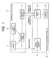
- FIG. 1 is a block diagram illustrating a configuration of an embodiment.
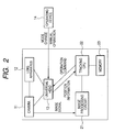
- FIG. 2 is a block diagram illustrating a configuration of a variation.
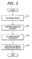
- FIG. 3 is a flow chart illustrating procedures.
- FIG. 4 illustrates a method for collecting color information of an object.
- FIG. 5 illustrates a method for selecting an arbitrary area.
- FIG. 6 is an operational flow chart for acquiring trace data.
- FIG. 7 illustrates trace data acquired.
- FIG. 8 is a graph illustrating size data of an object having complemented data.
- FIG. 9 is an elevation view of an operation display.
- FIG. 10 illustrates trace data compensated for.
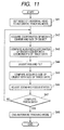
- FIG. 11 is an operational flow chart for an automatic tracking mode when color recognition is used for object recognition.
- FIG. 12 is an operational flow chart for an automatic tracking mode when pattern matching is used for object recognition.
- the universal head system 10 includes a TV camera 11, a lens apparatus 12 attached to the TV camera 11, an universal head 13 for driving the TV camera 11 to pan and tilt and an operating device 14 for controlling the universal head 13. Further, a tracking processing apparatus 20 located separately from the universal head system 10 includes an image processing circuit 21, a tracking CPU 22 and a memory 23.
- the image processing circuit 21 receives an image signal from the camera 11 and extracts size and shape information of an object necessary for tracking from the signal to transmit it to the tracking CPU 22.
- the tracking CPU 22 based on the feedback information from the image processing circuit 21, computes a controlled variable to be manipulated at the time and commands the operating device 14, and the operating device 14 transmits an operation command to the universal head 13 to manipulate the TV camera 11.
- the tracking processing apparatus 20 is configured to control the operating device 14, the operating device 14 may be used only for mode change of the universal head 13 and manual operation, with the tracking processing apparatus 20 being located on the side of the universal head system 10 and the operating device 14 outside, as shown in FIG. 2.
- FIG. 3 is a flow chart illustrating a sequence of operations of the tracking processing apparatus 20.
- An object is recognized in an image by sequential mode switching of the universal head system 10 performed by the image processing circuit 21 from an object recognition mode to a trace data acquisition mode, then to a trace data edit mode (step S11).
- step S12 the object is traced in advance (step S12), then trace data is edited and recorded (step S13), and finally in an automatic tracking mode, the object is automatically tracked in a composition as intended by a photographer (step 14).
- Procedures for recognizing the object in step 11 are, first setting of the universal head system 10 to the object recognition mode, then, for example as shown in FIG. 4, acquisition of a still image showing up an airplane as an object, and selection by a photographer of a color area of the fuselage in the airplane by which the object is most characterized.
- the tracking CPU 22 will compute an average value of color which occupies the largest area of this area or which is present in the selected area, and record the value as color information in the memory 23.
- two-dimensional array corresponding to pixels in an image plane may be provided such that when the color information for each of the pixels is within a certain threshold from the color of the object recorded as described above, a relevant element of the array is set to "1" and otherwise to "0". A portion which is the largest area among areas distinguished in such a manner is recognized as a final object.
- the final object is defined as the largest area in the method described above, a photographer may select an area to be the final object by using a click etc. from areas displayed which are larger than a certain level as shown in FIG. 5.
- FIG. 6 is an operational flow chart illustrating steps S12 and S13 shown in FIG. 3 up to trace data recording.
- a photographer sets the universal head system 10 to the trace data acquisition mode (step S21), then picks up manually an image in a composition intended to record (step S22).
- the universal head system 10 transmits pan and tilt position information through the tracking CPU 22 to the memory 23 at a regular period (step S23).
- an image picked up by the TV camera 11 is transmitted to the image processing circuit 21 (step S24), then the object is recognized in the method as described above, subsequently a median point of the object is computed therefrom (step S25), and position information of the median point is transmitted to the memory 23 (step S26).
- four data sets i.e. the pan and tilt positions of the universal head 13, and X and Y coordinates of the median point of the object are stored in the memory 23 as a two-dimensional array.
- a position of the object after a certain period of time elapsed from the start may be determined from an interval between data acquiring times and indexes of an array indicating what number data is.
- the operating device 14 may, for example include a structure that allows acquisition of an image as a still image to be performed by a push of a switch, and a photographer will push the switch at a key point that a desired composition is formed.
- an image may be automatically taken regularly at a certain interval (step S27) to acquire a plurality of still images (step S28). Accordingly, pan and tilt data regular at a certain interval as shown in FIG. 7, and X and Y coordinates of the object median point in an image plane similarly to these may be obtained, and also still image data will be at a certain time stored in the memory 23.
- an object size at an acquiring time of a still image is acquired with the method described above (step S30).
- This data may be complemented by using a data complementing method, for example linear interpolation or spline interpolation, and as a result, an object size complemented at the time computed by the data complementing is also added to the two-dimensional array, as shown in FIG. 8.
- the size of the abject and the position of the median point which are contained in a still image to be a key point and are present in an image plane at the time, and an interval between respective images are displayed on, for example a display as shown in FIG. 9. Then, by changing the size, the position of the median point and the interval between images to arbitrary values and complementing data once again, final trace data is recorded in the memory 23.
- FIG. 11 is an operational flow chart of procedures for the automatic tracking function in step S14 shown in FIG. 3.
- the universal head system 10 is set to the automatic tracking mode (step S41)
- the tracking CPU 22 starts to perform automatic tracking
- the tracking processing apparatus 20 acquires the coordinate of the median point and the size of a moving object to be targeted from the image processing circuit 21 (step S42).
- the coordinate of the median point obtained is compared to the coordinate in the trace data (step S43), and pan and tilt are adjusted to fit the trace data (step S44).
- zoom may be adjusted to fit the trace data (step S46). Because this zoom adjustment may cause focus to change, focus will be changed by an auto focusing function and the like.
- a lens provided with CAFS Constant Angle Focusing System
- zoom and focus adjustments may be repeated.
- an image is made to be such that it has the same size of the object as that in the obtained data of the object and is in focus state.
- the color information is used for object recognition, while, as another method, a method using pattern matching on the basis of shape for object recognition may be conceivable.
- pattern matching on the basis of shape normalized correlation between two images and the maximal value of the image correlation will be found out.
- an object is recognized in shape, then by matching the object in a next still image to the recognized object to obtain a parallel shift amount and ratios of magnification and contraction thereof, automatic tracking may be performed.
- a recognition method may be such that two images of an object to be targeted are picked up during moving, and then an area which is picked up in both two images computed from position information of the universal head 13 is defined as a comparison frame.
- a comparison frame In this comparison frame, a delta between the two images is acquired, and thereby a moving object is recognized.
- the moving object having the largest area may be selected from them, or a photographer may select as shown in FIG. 5.
- the trace data is acquired, edited and recorded similarly to the case of the color recognition, while, in the case of the pattern matching, size information of the object may not be required. Therefore, in sequence from the start, four data sets, i.e. pan and tilt positions of the universal head 13, and X and Y coordinates of the median point of the object in an image plane are stored in the memory as a two-dimensional array.
- FIG. 12 is a flow chart for the automatic tracking mode when the pattern matching is used.
- the universal head 13 is set to the automatic tracking mode similarly to the case of the color recognition (step S51).
- step S54 By means of this computation of the shift amount, pan, tilt and zoom data to the next time of image pickup of the trace data is corrected for (step S54), and for a period to the next time of image pickup, pan, tilt and zoom is controlled based on the trace data (step S55).
- step S57 it is determined whether any more data to process is present (step S56), and if any, returning to step S52, and if not, the automatic tracking ends (step S57).
- the present invention provides an image pickup apparatus for automatically tracking an object to pick up an image of the object, and the image apparatus comprises; a lens apparatus including a zoom lens and a focus lens, the lens apparatus picking up an image of the object; a camera device for picking up an image of the object acquired by the lens apparatus; a universal head for driving pan and tilt of the camera device; a memory for recording trace data of the universal head and image information picked up in synchronization with the trace data; an object recognizing circuit for recognizing the object; a shift amount detection unit for detecting a shift amount between the object and the trace data; and a control device for controlling the driving operation of the universal head based on the trace data and the shift amount.
Landscapes
- Engineering & Computer Science (AREA)
- Physics & Mathematics (AREA)
- Multimedia (AREA)
- Electromagnetism (AREA)
- General Physics & Mathematics (AREA)
- Radar, Positioning & Navigation (AREA)
- Remote Sensing (AREA)
- Studio Devices (AREA)
- Accessories Of Cameras (AREA)
Applications Claiming Priority (1)
| Application Number | Priority Date | Filing Date | Title |
|---|---|---|---|
| JP2005266058A JP4745769B2 (ja) | 2005-09-13 | 2005-09-13 | カメラ雲台装置 |
Publications (3)
| Publication Number | Publication Date |
|---|---|
| EP1764622A2 true EP1764622A2 (de) | 2007-03-21 |
| EP1764622A3 EP1764622A3 (de) | 2008-07-16 |
| EP1764622B1 EP1764622B1 (de) | 2011-08-10 |
Family
ID=37529268
Family Applications (1)
| Application Number | Title | Priority Date | Filing Date |
|---|---|---|---|
| EP06120477A Not-in-force EP1764622B1 (de) | 2005-09-13 | 2006-09-12 | Biderfassungsgerät |
Country Status (4)
| Country | Link |
|---|---|
| US (1) | US7916172B2 (de) |
| EP (1) | EP1764622B1 (de) |
| JP (1) | JP4745769B2 (de) |
| AT (1) | ATE520039T1 (de) |
Families Citing this family (20)
| Publication number | Priority date | Publication date | Assignee | Title |
|---|---|---|---|---|
| JP4720673B2 (ja) * | 2006-08-16 | 2011-07-13 | 株式会社ニコン | 被写体追尾装置およびカメラ |
| WO2008001575A1 (fr) | 2006-06-28 | 2008-01-03 | Nikon Corporation | Dispositif de localisation, dispositif de mise au point automatique et appareil photographique |
| JP4709101B2 (ja) * | 2006-09-01 | 2011-06-22 | キヤノン株式会社 | 自動追尾カメラ装置 |
| JP4969269B2 (ja) * | 2007-02-21 | 2012-07-04 | アルパイン株式会社 | 画像処理装置 |
| US8390729B2 (en) * | 2007-09-05 | 2013-03-05 | International Business Machines Corporation | Method and apparatus for providing a video image having multiple focal lengths |
| JP4835616B2 (ja) * | 2008-03-10 | 2011-12-14 | トヨタ自動車株式会社 | 動作教示システム及び動作教示方法 |
| KR101627185B1 (ko) * | 2009-04-24 | 2016-06-03 | 삼성전자 주식회사 | 영상촬영장치의 제어방법 |
| JP5226600B2 (ja) * | 2009-04-28 | 2013-07-03 | 富士フイルム株式会社 | 画像変形装置およびその動作制御方法 |
| US10168153B2 (en) | 2010-12-23 | 2019-01-01 | Trimble Inc. | Enhanced position measurement systems and methods |
| US9235763B2 (en) * | 2012-11-26 | 2016-01-12 | Trimble Navigation Limited | Integrated aerial photogrammetry surveys |
| JP2013201793A (ja) * | 2013-07-11 | 2013-10-03 | Nikon Corp | 撮像装置 |
| JP6753460B2 (ja) | 2016-03-08 | 2020-09-09 | ソニー株式会社 | 情報処理装置、および情報処理方法、並びにプログラム |
| US10586349B2 (en) | 2017-08-24 | 2020-03-10 | Trimble Inc. | Excavator bucket positioning via mobile device |
| US11438513B2 (en) | 2018-08-01 | 2022-09-06 | Sony Corporation | Drive control device and drive control method |
| JP7328849B2 (ja) | 2019-09-25 | 2023-08-17 | キヤノン株式会社 | 撮像装置、システム、撮像装置の制御方法、プログラム |
| JP2021052325A (ja) * | 2019-09-25 | 2021-04-01 | キヤノン株式会社 | 撮像装置、システム、撮像装置の制御方法、プログラム |
| JP7307643B2 (ja) | 2019-09-25 | 2023-07-12 | キヤノン株式会社 | 撮像装置、システム、撮像装置の制御方法、プログラム |
| US10943360B1 (en) | 2019-10-24 | 2021-03-09 | Trimble Inc. | Photogrammetric machine measure up |
| US12047681B2 (en) * | 2021-04-21 | 2024-07-23 | Canon Kabushiki Kaisha | Image pickup apparatus including tilt driving portion, control method, and memory medium |
| JP2023007575A (ja) * | 2021-07-02 | 2023-01-19 | キヤノン株式会社 | 撮像装置、撮像装置の制御方法、プログラム、及び情報処理装置 |
Citations (1)
| Publication number | Priority date | Publication date | Assignee | Title |
|---|---|---|---|---|
| US5204749A (en) | 1984-05-25 | 1993-04-20 | Canon Kabushiki Kaisha | Automatic follow-up focus detecting device and automatic follow-up device |
Family Cites Families (13)
| Publication number | Priority date | Publication date | Assignee | Title |
|---|---|---|---|---|
| JPH0614698B2 (ja) | 1983-05-13 | 1994-02-23 | 株式会社日立製作所 | 自動追尾カメラ |
| JPH0695008B2 (ja) * | 1987-12-11 | 1994-11-24 | 株式会社東芝 | 監視装置 |
| US5111288A (en) * | 1988-03-02 | 1992-05-05 | Diamond Electronics, Inc. | Surveillance camera system |
| JP2868087B2 (ja) | 1988-04-07 | 1999-03-10 | 富士写真光機株式会社 | テレビカメラ用操作装置 |
| JPH05219421A (ja) * | 1992-01-31 | 1993-08-27 | Nippon Hoso Kyokai <Nhk> | テレビジョンカメラの制御装置 |
| US5912980A (en) * | 1995-07-13 | 1999-06-15 | Hunke; H. Martin | Target acquisition and tracking |
| US6445409B1 (en) | 1997-05-14 | 2002-09-03 | Hitachi Denshi Kabushiki Kaisha | Method of distinguishing a moving object and apparatus of tracking and monitoring a moving object |
| EP0908846A3 (de) * | 1997-10-07 | 2000-03-29 | Canon Kabushiki Kaisha | Verfahren und Einrichtung zur Feststellung eines sich bewegenden Objektes |
| JPH11352541A (ja) * | 1998-06-09 | 1999-12-24 | Minolta Co Ltd | カメラ |
| JP3597089B2 (ja) * | 1999-08-31 | 2004-12-02 | 松下電器産業株式会社 | 監視カメラ装置とそのオートトレース実施方法 |
| JP4403483B2 (ja) * | 2001-02-13 | 2010-01-27 | フジノン株式会社 | 自動追尾装置 |
| JP2003069884A (ja) * | 2001-08-28 | 2003-03-07 | Fuji Photo Film Co Ltd | 撮影カメラの被写体自動追従装置 |
| JP2006222690A (ja) * | 2005-02-09 | 2006-08-24 | Nikon Corp | 電子カメラ |
-
2005
- 2005-09-13 JP JP2005266058A patent/JP4745769B2/ja not_active Expired - Fee Related
-
2006
- 2006-09-12 US US11/531,085 patent/US7916172B2/en active Active
- 2006-09-12 AT AT06120477T patent/ATE520039T1/de not_active IP Right Cessation
- 2006-09-12 EP EP06120477A patent/EP1764622B1/de not_active Not-in-force
Patent Citations (1)
| Publication number | Priority date | Publication date | Assignee | Title |
|---|---|---|---|---|
| US5204749A (en) | 1984-05-25 | 1993-04-20 | Canon Kabushiki Kaisha | Automatic follow-up focus detecting device and automatic follow-up device |
Also Published As
| Publication number | Publication date |
|---|---|
| JP2007081754A (ja) | 2007-03-29 |
| ATE520039T1 (de) | 2011-08-15 |
| JP4745769B2 (ja) | 2011-08-10 |
| EP1764622A3 (de) | 2008-07-16 |
| EP1764622B1 (de) | 2011-08-10 |
| US20070058046A1 (en) | 2007-03-15 |
| US7916172B2 (en) | 2011-03-29 |
Similar Documents
| Publication | Publication Date | Title |
|---|---|---|
| EP1764622B1 (de) | Biderfassungsgerät | |
| US7548269B2 (en) | System for autofocusing a moving object | |
| US5631697A (en) | Video camera capable of automatic target tracking | |
| US6757013B2 (en) | Image pickup apparatus with electronic and optical zoom functions | |
| JP4697810B2 (ja) | 自動追尾装置及び自動追尾方法 | |
| JP5473551B2 (ja) | オートフォーカスシステム | |
| US7590343B2 (en) | Autofocus system | |
| US20070196091A1 (en) | Auto focus unit and digital camera | |
| KR100676232B1 (ko) | 물체추적방법, 물체추적장치 및 물체추적을 행하기 위한 계산기의 프로그램을 기록한 컴퓨터로 읽을 수 있는 기록매체 | |
| US20110234834A1 (en) | Imaging apparatus and image processing method | |
| US9317748B2 (en) | Tracking apparatus | |
| US8203643B2 (en) | Automatic focusing device | |
| US20070196089A1 (en) | Auto focus unit and camera | |
| EP2006857A1 (de) | Bildverarbeitungsvorrichtung, Bildverarbeitungsverfahren und Programm | |
| GB2216743A (en) | Image sensing apparatus | |
| JP2005338352A (ja) | オートフォーカスシステム | |
| JP5317607B2 (ja) | 自動追尾カメラの制御装置及び自動追尾カメラシステム及び自動追尾カメラの制御方法 | |
| JP2006058431A (ja) | オートフォーカスシステム | |
| JP4596246B2 (ja) | オートフォーカスシステム | |
| JP4403483B2 (ja) | 自動追尾装置 | |
| JP2002135766A (ja) | 自動追尾装置 | |
| JP2000232642A (ja) | 画像処理装置および方法、撮像システム、並びに提供媒体 | |
| JP2005184266A (ja) | 撮像装置 | |
| US12593126B2 (en) | Photographing device and focus control method | |
| JPH0545554A (ja) | レンズ制御装置 |
Legal Events
| Date | Code | Title | Description |
|---|---|---|---|
| PUAI | Public reference made under article 153(3) epc to a published international application that has entered the european phase |
Free format text: ORIGINAL CODE: 0009012 |
|
| AK | Designated contracting states |
Kind code of ref document: A2 Designated state(s): AT BE BG CH CY CZ DE DK EE ES FI FR GB GR HU IE IS IT LI LT LU LV MC NL PL PT RO SE SI SK TR |
|
| AX | Request for extension of the european patent |
Extension state: AL BA HR MK YU |
|
| PUAL | Search report despatched |
Free format text: ORIGINAL CODE: 0009013 |
|
| AK | Designated contracting states |
Kind code of ref document: A3 Designated state(s): AT BE BG CH CY CZ DE DK EE ES FI FR GB GR HU IE IS IT LI LT LU LV MC NL PL PT RO SE SI SK TR |
|
| AX | Request for extension of the european patent |
Extension state: AL BA HR MK RS |
|
| 17P | Request for examination filed |
Effective date: 20090116 |
|
| AKX | Designation fees paid |
Designated state(s): AT BE BG CH CY CZ DE DK EE ES FI FR GB GR HU IE IS IT LI LT LU LV MC NL PL PT RO SE SI SK TR |
|
| 17Q | First examination report despatched |
Effective date: 20090518 |
|
| GRAP | Despatch of communication of intention to grant a patent |
Free format text: ORIGINAL CODE: EPIDOSNIGR1 |
|
| GRAS | Grant fee paid |
Free format text: ORIGINAL CODE: EPIDOSNIGR3 |
|
| GRAA | (expected) grant |
Free format text: ORIGINAL CODE: 0009210 |
|
| AK | Designated contracting states |
Kind code of ref document: B1 Designated state(s): AT BE BG CH CY CZ DE DK EE ES FI FR GB GR HU IE IS IT LI LT LU LV MC NL PL PT RO SE SI SK TR |
|
| REG | Reference to a national code |
Ref country code: GB Ref legal event code: FG4D |
|
| REG | Reference to a national code |
Ref country code: CH Ref legal event code: EP |
|
| REG | Reference to a national code |
Ref country code: IE Ref legal event code: FG4D |
|
| REG | Reference to a national code |
Ref country code: DE Ref legal event code: R096 Ref document number: 602006023622 Country of ref document: DE Effective date: 20111117 |
|
| REG | Reference to a national code |
Ref country code: NL Ref legal event code: VDEP Effective date: 20110810 |
|
| LTIE | Lt: invalidation of european patent or patent extension |
Effective date: 20110810 |
|
| PG25 | Lapsed in a contracting state [announced via postgrant information from national office to epo] |
Ref country code: LT Free format text: LAPSE BECAUSE OF FAILURE TO SUBMIT A TRANSLATION OF THE DESCRIPTION OR TO PAY THE FEE WITHIN THE PRESCRIBED TIME-LIMIT Effective date: 20110810 Ref country code: SE Free format text: LAPSE BECAUSE OF FAILURE TO SUBMIT A TRANSLATION OF THE DESCRIPTION OR TO PAY THE FEE WITHIN THE PRESCRIBED TIME-LIMIT Effective date: 20110810 Ref country code: PT Free format text: LAPSE BECAUSE OF FAILURE TO SUBMIT A TRANSLATION OF THE DESCRIPTION OR TO PAY THE FEE WITHIN THE PRESCRIBED TIME-LIMIT Effective date: 20111212 Ref country code: FI Free format text: LAPSE BECAUSE OF FAILURE TO SUBMIT A TRANSLATION OF THE DESCRIPTION OR TO PAY THE FEE WITHIN THE PRESCRIBED TIME-LIMIT Effective date: 20110810 Ref country code: IS Free format text: LAPSE BECAUSE OF FAILURE TO SUBMIT A TRANSLATION OF THE DESCRIPTION OR TO PAY THE FEE WITHIN THE PRESCRIBED TIME-LIMIT Effective date: 20111210 Ref country code: NL Free format text: LAPSE BECAUSE OF FAILURE TO SUBMIT A TRANSLATION OF THE DESCRIPTION OR TO PAY THE FEE WITHIN THE PRESCRIBED TIME-LIMIT Effective date: 20110810 |
|
| REG | Reference to a national code |
Ref country code: AT Ref legal event code: MK05 Ref document number: 520039 Country of ref document: AT Kind code of ref document: T Effective date: 20110810 |
|
| PG25 | Lapsed in a contracting state [announced via postgrant information from national office to epo] |
Ref country code: GR Free format text: LAPSE BECAUSE OF FAILURE TO SUBMIT A TRANSLATION OF THE DESCRIPTION OR TO PAY THE FEE WITHIN THE PRESCRIBED TIME-LIMIT Effective date: 20111111 Ref country code: PL Free format text: LAPSE BECAUSE OF FAILURE TO SUBMIT A TRANSLATION OF THE DESCRIPTION OR TO PAY THE FEE WITHIN THE PRESCRIBED TIME-LIMIT Effective date: 20110810 Ref country code: SI Free format text: LAPSE BECAUSE OF FAILURE TO SUBMIT A TRANSLATION OF THE DESCRIPTION OR TO PAY THE FEE WITHIN THE PRESCRIBED TIME-LIMIT Effective date: 20110810 Ref country code: AT Free format text: LAPSE BECAUSE OF FAILURE TO SUBMIT A TRANSLATION OF THE DESCRIPTION OR TO PAY THE FEE WITHIN THE PRESCRIBED TIME-LIMIT Effective date: 20110810 Ref country code: CY Free format text: LAPSE BECAUSE OF FAILURE TO SUBMIT A TRANSLATION OF THE DESCRIPTION OR TO PAY THE FEE WITHIN THE PRESCRIBED TIME-LIMIT Effective date: 20110810 Ref country code: LV Free format text: LAPSE BECAUSE OF FAILURE TO SUBMIT A TRANSLATION OF THE DESCRIPTION OR TO PAY THE FEE WITHIN THE PRESCRIBED TIME-LIMIT Effective date: 20110810 |
|
| PG25 | Lapsed in a contracting state [announced via postgrant information from national office to epo] |
Ref country code: BE Free format text: LAPSE BECAUSE OF FAILURE TO SUBMIT A TRANSLATION OF THE DESCRIPTION OR TO PAY THE FEE WITHIN THE PRESCRIBED TIME-LIMIT Effective date: 20110810 |
|
| PG25 | Lapsed in a contracting state [announced via postgrant information from national office to epo] |
Ref country code: SK Free format text: LAPSE BECAUSE OF FAILURE TO SUBMIT A TRANSLATION OF THE DESCRIPTION OR TO PAY THE FEE WITHIN THE PRESCRIBED TIME-LIMIT Effective date: 20110810 Ref country code: MC Free format text: LAPSE BECAUSE OF NON-PAYMENT OF DUE FEES Effective date: 20110930 Ref country code: CZ Free format text: LAPSE BECAUSE OF FAILURE TO SUBMIT A TRANSLATION OF THE DESCRIPTION OR TO PAY THE FEE WITHIN THE PRESCRIBED TIME-LIMIT Effective date: 20110810 |
|
| REG | Reference to a national code |
Ref country code: CH Ref legal event code: PL |
|
| PG25 | Lapsed in a contracting state [announced via postgrant information from national office to epo] |
Ref country code: IT Free format text: LAPSE BECAUSE OF FAILURE TO SUBMIT A TRANSLATION OF THE DESCRIPTION OR TO PAY THE FEE WITHIN THE PRESCRIBED TIME-LIMIT Effective date: 20110810 Ref country code: RO Free format text: LAPSE BECAUSE OF FAILURE TO SUBMIT A TRANSLATION OF THE DESCRIPTION OR TO PAY THE FEE WITHIN THE PRESCRIBED TIME-LIMIT Effective date: 20110810 Ref country code: EE Free format text: LAPSE BECAUSE OF FAILURE TO SUBMIT A TRANSLATION OF THE DESCRIPTION OR TO PAY THE FEE WITHIN THE PRESCRIBED TIME-LIMIT Effective date: 20110810 |
|
| PLBE | No opposition filed within time limit |
Free format text: ORIGINAL CODE: 0009261 |
|
| STAA | Information on the status of an ep patent application or granted ep patent |
Free format text: STATUS: NO OPPOSITION FILED WITHIN TIME LIMIT |
|
| REG | Reference to a national code |
Ref country code: IE Ref legal event code: MM4A |
|
| PG25 | Lapsed in a contracting state [announced via postgrant information from national office to epo] |
Ref country code: DK Free format text: LAPSE BECAUSE OF FAILURE TO SUBMIT A TRANSLATION OF THE DESCRIPTION OR TO PAY THE FEE WITHIN THE PRESCRIBED TIME-LIMIT Effective date: 20110810 |
|
| 26N | No opposition filed |
Effective date: 20120511 |
|
| PG25 | Lapsed in a contracting state [announced via postgrant information from national office to epo] |
Ref country code: LI Free format text: LAPSE BECAUSE OF NON-PAYMENT OF DUE FEES Effective date: 20110930 Ref country code: CH Free format text: LAPSE BECAUSE OF NON-PAYMENT OF DUE FEES Effective date: 20110930 Ref country code: IE Free format text: LAPSE BECAUSE OF NON-PAYMENT OF DUE FEES Effective date: 20110912 |
|
| REG | Reference to a national code |
Ref country code: DE Ref legal event code: R097 Ref document number: 602006023622 Country of ref document: DE Effective date: 20120511 |
|
| PG25 | Lapsed in a contracting state [announced via postgrant information from national office to epo] |
Ref country code: ES Free format text: LAPSE BECAUSE OF FAILURE TO SUBMIT A TRANSLATION OF THE DESCRIPTION OR TO PAY THE FEE WITHIN THE PRESCRIBED TIME-LIMIT Effective date: 20111121 |
|
| PG25 | Lapsed in a contracting state [announced via postgrant information from national office to epo] |
Ref country code: LU Free format text: LAPSE BECAUSE OF NON-PAYMENT OF DUE FEES Effective date: 20110912 |
|
| PG25 | Lapsed in a contracting state [announced via postgrant information from national office to epo] |
Ref country code: BG Free format text: LAPSE BECAUSE OF FAILURE TO SUBMIT A TRANSLATION OF THE DESCRIPTION OR TO PAY THE FEE WITHIN THE PRESCRIBED TIME-LIMIT Effective date: 20111110 |
|
| PG25 | Lapsed in a contracting state [announced via postgrant information from national office to epo] |
Ref country code: TR Free format text: LAPSE BECAUSE OF FAILURE TO SUBMIT A TRANSLATION OF THE DESCRIPTION OR TO PAY THE FEE WITHIN THE PRESCRIBED TIME-LIMIT Effective date: 20110810 |
|
| PG25 | Lapsed in a contracting state [announced via postgrant information from national office to epo] |
Ref country code: HU Free format text: LAPSE BECAUSE OF FAILURE TO SUBMIT A TRANSLATION OF THE DESCRIPTION OR TO PAY THE FEE WITHIN THE PRESCRIBED TIME-LIMIT Effective date: 20110810 |
|
| REG | Reference to a national code |
Ref country code: FR Ref legal event code: PLFP Year of fee payment: 11 |
|
| REG | Reference to a national code |
Ref country code: FR Ref legal event code: PLFP Year of fee payment: 12 |
|
| REG | Reference to a national code |
Ref country code: FR Ref legal event code: PLFP Year of fee payment: 13 |
|
| PGFP | Annual fee paid to national office [announced via postgrant information from national office to epo] |
Ref country code: FR Payment date: 20210819 Year of fee payment: 16 |
|
| PGFP | Annual fee paid to national office [announced via postgrant information from national office to epo] |
Ref country code: GB Payment date: 20210820 Year of fee payment: 16 |
|
| GBPC | Gb: european patent ceased through non-payment of renewal fee |
Effective date: 20220912 |
|
| PG25 | Lapsed in a contracting state [announced via postgrant information from national office to epo] |
Ref country code: FR Free format text: LAPSE BECAUSE OF NON-PAYMENT OF DUE FEES Effective date: 20220930 |
|
| PG25 | Lapsed in a contracting state [announced via postgrant information from national office to epo] |
Ref country code: GB Free format text: LAPSE BECAUSE OF NON-PAYMENT OF DUE FEES Effective date: 20220912 |
|
| PGFP | Annual fee paid to national office [announced via postgrant information from national office to epo] |
Ref country code: DE Payment date: 20230822 Year of fee payment: 18 |
|
| REG | Reference to a national code |
Ref country code: DE Ref legal event code: R119 Ref document number: 602006023622 Country of ref document: DE |
|
| PG25 | Lapsed in a contracting state [announced via postgrant information from national office to epo] |
Ref country code: DE Free format text: LAPSE BECAUSE OF NON-PAYMENT OF DUE FEES Effective date: 20250401 |