EP1764173A2 - Vorrichtung zum Herstellen eines Formteils - Google Patents
Vorrichtung zum Herstellen eines Formteils Download PDFInfo
- Publication number
- EP1764173A2 EP1764173A2 EP06013880A EP06013880A EP1764173A2 EP 1764173 A2 EP1764173 A2 EP 1764173A2 EP 06013880 A EP06013880 A EP 06013880A EP 06013880 A EP06013880 A EP 06013880A EP 1764173 A2 EP1764173 A2 EP 1764173A2
- Authority
- EP
- European Patent Office
- Prior art keywords
- piston
- cylinder
- guide means
- central axis
- tool
- Prior art date
- Legal status (The legal status is an assumption and is not a legal conclusion. Google has not performed a legal analysis and makes no representation as to the accuracy of the status listed.)
- Granted
Links
- 239000000843 powder Substances 0.000 title claims abstract description 17
- 238000000465 moulding Methods 0.000 title abstract description 10
- 239000002184 metal Substances 0.000 claims abstract description 6
- 239000000463 material Substances 0.000 claims description 7
- 230000009969 flowable effect Effects 0.000 claims description 2
- 239000007788 liquid Substances 0.000 abstract 1
- 238000006073 displacement reaction Methods 0.000 description 3
- 238000004519 manufacturing process Methods 0.000 description 3
- 230000006835 compression Effects 0.000 description 2
- 238000007906 compression Methods 0.000 description 2
- 238000007598 dipping method Methods 0.000 description 1
- 239000000945 filler Substances 0.000 description 1
- 238000003780 insertion Methods 0.000 description 1
- 230000037431 insertion Effects 0.000 description 1
- 230000035515 penetration Effects 0.000 description 1
- 238000005245 sintering Methods 0.000 description 1
Images
Classifications
-
- B—PERFORMING OPERATIONS; TRANSPORTING
- B30—PRESSES
- B30B—PRESSES IN GENERAL
- B30B11/00—Presses specially adapted for forming shaped articles from material in particulate or plastic state, e.g. briquetting presses, tabletting presses
- B30B11/02—Presses specially adapted for forming shaped articles from material in particulate or plastic state, e.g. briquetting presses, tabletting presses using a ram exerting pressure on the material in a moulding space
-
- B—PERFORMING OPERATIONS; TRANSPORTING
- B22—CASTING; POWDER METALLURGY
- B22F—WORKING METALLIC POWDER; MANUFACTURE OF ARTICLES FROM METALLIC POWDER; MAKING METALLIC POWDER; APPARATUS OR DEVICES SPECIALLY ADAPTED FOR METALLIC POWDER
- B22F3/00—Manufacture of workpieces or articles from metallic powder characterised by the manner of compacting or sintering; Apparatus specially adapted therefor ; Presses and furnaces
- B22F3/02—Compacting only
- B22F3/03—Press-moulding apparatus therefor
-
- B—PERFORMING OPERATIONS; TRANSPORTING
- B30—PRESSES
- B30B—PRESSES IN GENERAL
- B30B15/00—Details of, or accessories for, presses; Auxiliary measures in connection with pressing
- B30B15/04—Frames; Guides
- B30B15/041—Guides
-
- F—MECHANICAL ENGINEERING; LIGHTING; HEATING; WEAPONS; BLASTING
- F15—FLUID-PRESSURE ACTUATORS; HYDRAULICS OR PNEUMATICS IN GENERAL
- F15B—SYSTEMS ACTING BY MEANS OF FLUIDS IN GENERAL; FLUID-PRESSURE ACTUATORS, e.g. SERVOMOTORS; DETAILS OF FLUID-PRESSURE SYSTEMS, NOT OTHERWISE PROVIDED FOR
- F15B15/00—Fluid-actuated devices for displacing a member from one position to another; Gearing associated therewith
- F15B15/08—Characterised by the construction of the motor unit
- F15B15/14—Characterised by the construction of the motor unit of the straight-cylinder type
- F15B15/1423—Component parts; Constructional details
- F15B15/1471—Guiding means other than in the end cap
Definitions
- the invention relates to a device for producing a molded part from powder, in particular from metal powder, from a powdery, doughy material, from a powder containing flowable material or from pre-pressed material having a tool on which in the manufacture of the molding a pressing force is exerted by a pressing device, wherein the tool for producing a desired molding contour has at least one piston-cylinder system with a central axis, which has a piston movable hydraulically relative to a cylinder in a travel direction.
- a generic device is from the US 5,498,147 known. There, a tool is described which has a plurality of concentric piston-cylinder units inserted into each other. To guide the entire tool in the machine, laterally arranged guide columns are provided, which pass through a cover plate of the tool.
- Devices of this type are used to produce molded parts of metal powder by pressing and subsequent sintering.
- stamp-like tools are used for the pressing of powdery material, which compress the powder introduced into a die by an axial pressing movement.
- At least one press die is inserted, which penetrates into the die.
- the die has a cavity which opens to the punch side is.
- the die opening is closed - except for a slight play - by the stamp.
- the stamp builds up by its penetration into the Matrizenhohlraum necessary for compression pressure.
- a plurality of punches are used, which can move in an axial direction.
- the punches can dive into an axially closed on one side mold or come in an axially open in both directions die from both axial directions. Occasionally, through mandrel rods are used, but primarily have no compression function, but a positive displacement function.
- the punches can also dip laterally into the die to create undercuts or other geometric shapes. To demould the molded part, these radially dipping punch are withdrawn so far that the demolding is not hindered.
- piston-cylinder systems For positioning of the individual stamps, these are connected to piston-cylinder systems or they are part of these systems. In this case, a number of pistons are arranged concentrically with each other. During pressing, they are moved in accordance with the contour of the molded part to be generated by a defined displacement relative to its cylinder.
- the individual piston-like stamps are guided in their cylinders characterized in that the piston rests with its radially outwardly facing cylindrical surface in the corresponding bore of the cylinder. It has been found, especially in the production of asymmetrical moldings, that tilting moments, the axis of which are perpendicular to the central axis of the tool, can cause problems. The existing leadership of the pistons in their cylinders is then no longer sufficient for a high-quality production. In addition, there may be problems when the rotationally symmetrical pistons in the cylinders uncontrolled around the Central axis can rotate. The known structural elements are then no longer sufficient to ensure a sufficiently accurate guidance of the pistons in their cylinders.
- the invention is therefore the object of a device of the type mentioned in such a way that the disadvantages mentioned are avoided. It should thus be ensured that even with off-center forces sufficient guidance of the piston is maintained in their cylinders and that a rotation of the piston to its cylinder about the central axis is not possible.
- This solution to this problem by the invention is characterized by a guide means, which guides at least one of the pistons relative to one of the cylinders in the direction of travel of the piston-cylinder system, wherein the guide means extends in the travel direction along an axis which is spaced from the central axis wherein the tool is designed as a replaceable adapter in the pressing device.
- the invention thus provides previously unknown in the prior art guide means which are at least partially at a distance from the central axis.
- the guide means is preferably suitable for receiving a tilting moment between the cylinder and the piston, wherein the tilting moment acts perpendicular to the central axis. Especially when asymmetric moldings have to be pressed and consequently there is no necessarily a symmetrical force distribution, the guide means ensure that no relative tilting between the piston and the cylinder can occur.
- the guide means comprises at least one rod which is fixedly arranged on the piston or on the cylinder is and which is guided in a guide (socket) in the cylinder or in the piston. It is particularly provided that a plurality of rods are arranged on the piston or on the cylinder; Advantageously, four rods are used, which are arranged on the piston or on the cylinder. These four rods can be arranged symmetrically to two mutually perpendicular planes.
- the rod may be attached to a support member fixed to the piston or cylinder.
- a number of piston-cylinder systems are arranged along the central axis.
- the pistons may be arranged concentrically with each other and at least two pistons may be adjacent to one another on facing lateral surfaces.
- the guide means can also guide a plurality of pistons and / or cylinders relative to one another.
- the individual pistons of the tool are guided improved in an advantageous manner, which is particularly their parallelism.
- the directional stability of the pistons is also improved.
- the guide rods are quick and easy to assemble and disassemble, as well as the sockets on the respective piston.
- the overall quality of the molded part is improved because the tool is provided with precisely working parts.
- a device 1 for producing a molded part is shown, with the metal powder 12 can be pressed into a molded part.
- the invention is not only suitable for the processing of powder. Frequently, an already preformed compact is re-pressed in a further step, especially in the final pressing at higher pressures.
- the device 1 consists essentially of a tool 2, which can be used in a pressing device 3.
- the pressing device 3 has a machine frame 13 with an upper cross member 14 and a lower cross member 15.
- an upper piston 16 is arranged in a cylinder, with which a pressing force can be applied downward.
- the lower cross member 15 carries a lower piston 17, with which a pressing force can be generated upwards.
- the tool 2 has a die 18, which receives the powder 12.
- a number of stamp pistons 5 arranged concentrically with one another are provided, which are arranged in respective cylinders 4 and can be moved or controlled relative to them.
- a piston-cylinder system Depending on a piston 5 forms together with this receiving cylinder 4, a piston-cylinder system, as it is already known as such. All pistons 5 and cylinders 4 are arranged concentrically around a central axis 6 in the exemplary embodiment.
- actuating the respective piston-cylinder systems 4, 5 By actuating the respective piston-cylinder systems 4, 5, a movement in the direction of travel V (corresponds to the present case the vertical direction) can be accomplished. Only mentioned in passing were stamp 19 and 20, which are actuated by the upper piston 16, and a filler 21 for the feed of the die 18 with powder 12th
- a guide means 7 which prevents tilting and excludes twisting.
- a plate-shaped support member 11 is fixed to the piston 5, to which in turn four rods 9 are fixedly arranged with a circular cross-section.
- the rods 9 are arranged displaceably in guides 10 in the cylinder 4 in the direction of travel V.
- the guides can be designed as tightly tolerated sliding bushes, which ensure that during the displacement of the piston 5 relative to the cylinder 4 in the direction of travel V, a high degree of parallelism of both elements 4, 5 is maintained.
- tilting moments M which act perpendicular to the direction of travel V, should have no influence on the parallelism between piston 5 and cylinder 4.
- the rods 9 are positioned so that their axis 8 is at a (radial) distance a from the central axis 6.
Landscapes
- Engineering & Computer Science (AREA)
- Mechanical Engineering (AREA)
- Manufacturing & Machinery (AREA)
- Physics & Mathematics (AREA)
- Fluid Mechanics (AREA)
- General Engineering & Computer Science (AREA)
- Powder Metallurgy (AREA)
- Press Drives And Press Lines (AREA)
- Press-Shaping Or Shaping Using Conveyers (AREA)
- Presses And Accessory Devices Thereof (AREA)
- Glass Compositions (AREA)
- Encapsulation Of And Coatings For Semiconductor Or Solid State Devices (AREA)
Abstract
Description
- Die Erfindung betrifft eine Vorrichtung zum Herstellen eines Formteils aus Pulver, insbesondere aus Metallpulver, aus einem ein Pulver enthaltenden, teigigen Material, aus einem ein Pulver enthaltenden, fließfähigen Material oder aus vorgepresstem Material, die ein Werkzeug aufweist, auf das bei der Herstellung des Formteils von einer Pressvorrichtung eine Druckkraft ausgeübt wird, wobei das Werkzeug zur Erzeugung einer gewünschten Formteilkontur mindestens ein Kolben-Zylinder-System mit einer Zentralachse aufweist, das einen hydraulisch relativ zu einem Zylinder in eine Verfahrrichtung bewegbaren Kolben hat.
- Eine gattungsgemäße Vorrichtung ist aus der
US 5,498,147 bekannt. Dort wird ein Werkzeug beschrieben, das eine Vielzahl von ineinander eingesetzte, konzentrische Kolben-Zylinder-Einheiten aufweist. Um das gesamte Werkzeug in der Maschine zu führen, sind seitlich angeordnete Führungssäulen vorgesehen, die eine Deckplatte des Werkzeugs durchsetzen. - Vorrichtungen dieser Art werden eingesetzt, um Formteile aus Metallpulver durch Pressen und anschließendes Sintern herzustellen. Hierbei werden für das Pressen von pulverförmigem Werkstoff stempelartige Werkzeuge eingesetzt, die in eine Matrize eingebrachtes Pulver durch eine axiale Pressbewegung komprimieren.
- Hierzu wird zumindest ein Pressstempel eingesetzt, der in die Matrize eindringt. In diesem Falle besitzt die Matrize einen Hohlraum, der zur Stempelseite hin geöffnet ist. Die Matrizenöffnung wird - bis auf ein geringfügiges Spiel - vom Stempel geschlossen. Der Stempel baut durch sein Eindringen in den Matrizenhohlraum den zur Verdichtung notwendigen Druck auf.
- Es kann auch vorgesehen werden, dass mehrere Stempel eingesetzt werden, die sich in eine Achsrichtung bewegen können. Die Stempel können dabei in eine axial einseitig geschlossene Matrize eintauchen oder bei einer axial in beiden Richtungen offenen Matrize aus beiden axialen Richtungen kommen. Gelegentlich werden auch durchgehende Dornstangen eingesetzt, die aber primär keine Verdichtungsfunktion, sondern eine Verdrängerfunktion haben. Die Stempel können auch seitlich in die Matrize eintauchen, um Hinterschneidungen oder sonstige geometrische Ausprägungen zu erzeugen. Zur Entformung des Formteils werden diese radial eintauchenden Stempel so weit zurückgezogen, dass die Entformung nicht behindert wird.
- Zur Positionierung der einzelnen Stempel sind diese mit Kolben-Zylinder-Systemen verbunden bzw. sie sind Teil dieser Systeme. Dabei ist eine Anzahl Kolben zueinander konzentrisch angeordnet. Beim Pressen werden sie gemäß der zu erzeugenden Kontur des Formteils um einen definierten Verschiebeweg relativ zu ihrem Zylinder bewegt.
- Bei den vorbekannten Lösungen werden die einzelnen kolbenartig ausgebildeten Stempel in ihren Zylindern dadurch geführt, dass der Kolben mit seiner radial nach außen weisenden zylindrischen Oberfläche in der entsprechenden Bohrung des Zylinders anliegt. Dabei hat es sich vor allem bei der Herstellung von unsymmetrischen Formteilen gezeigt, dass Kippmomente, deren Achse senkrecht zur Zentralachse des Werkzeugs stehen, Probleme verursachen können. Die vorhandene Führung der Kolben in ihren Zylindern reicht dann nicht mehr für eine qualitativ hochwertige Fertigung aus. Darüber hinaus kann es dann zu Problemen kommen, wenn die rotationssymmetrischen Kolben in den Zylindern unkontrolliert um die Zentralachse drehen können. Die bekannten konstruktiven Elemente reichen dann nicht mehr aus, um eine hinreichend genaue Führung der Kolben in ihren Zylindern sicherzustellen.
- Der Erfindung liegt daher die Aufgabe zugrunde, eine Vorrichtung der eingangs genannten Art so fortzubilden, dass die genannten Nachteile vermieden werden. Es soll also sichergestellt werden, dass auch bei außermittigen Kräften eine hinreichende Führung der Kolben in ihren Zylindern erhalten bleibt und dass ein Verdrehen des Kolbens zu seinem Zylinder um die Zentralachse nicht möglich ist.
- Diese Lösung dieser Aufgabe durch die Erfindung ist gekennzeichnet durch ein Führungsmittel, das zumindest einen der Kolben relativ zu einem der Zylinder in Verfahrrichtung des Kolben-Zylinder-Systems führt, wobei sich das Führungsmittel in Verfahrrichtung entlang einer Achse erstreckt, die von der Zentralachse beabstandet ist, wobei das Werkzeug als auswechselbarer Adapter in der Pressvorrichtung ausgebildet ist.
- Die Erfindung sieht also bisher im Stand der Technik nicht bekannte Führungsmittel vor, die sich zumindest teilweise im Abstand von der Zentralachse befinden.
- Das Führungsmittel ist dabei bevorzugt zur Aufnahme eines Kippmoments zwischen dem Zylinder und dem Kolben geeignet ist, wobei das Kippmoment senkrecht zur Zentralachse wirkt. Gerade, wenn unsymmetrische Formteile gepresst werden müssen und sich folglich nicht notwendiger Weise eine symmetrische Kraftverteilung ergibt, stellen die Führungsmittel sicher, dass kein relatives Verkippen zwischen Kolben und Zylinder auftreten kann.
- Eine bevorzugte Ausgestaltung der Erfindung sieht vor, dass das Führungsmittel mindestens eine Stange aufweist, die am Kolben oder am Zylinder fest angeordnet ist und die in einer Führung (Buchse) im Zylinder oder im Kolben geführt ist. Dabei ist insbesondere vorgesehen, dass mehrere Stangen am Kolben oder am Zylinder angeordnet sind; dabei kommen mit Vorteil vier Stangen zum Einsatz, die am Kolben oder am Zylinder angeordnet sind. Diese vier Stangen können symmetrisch zu zwei aufeinander senkrecht stehenden Ebenen angeordnet sein.
- Die Stange kann an einem Trägerelement befestigt sein, die am Kolben oder am Zylinder festgelegt ist.
- Vorzugsweise ist eine Anzahl Kolben-Zylinder-Systeme entlang der Zentralachse angeordnet. Die Kolben können dabei konzentrisch zueinander angeordnet sein und mindestens zwei Kolben können an zugewandten Mantelflächen aneinander liegen. Dabei kann das Führungsmittel grundsätzlich auch mehrere Kolben und/oder Zylinder relativ zueinander führen.
- Mit der erfindungsgemäßen Ausführung wird erreicht, dass ein Verdrehen des Kolbens relativ zu seinem Zylinder nicht möglich ist, was vor allem beim Pressen unsymmetrischer Formteile wichtig ist.
- Weiterhin wird eine verbesserte Führung zwischen Kolben und Zylindern erreicht, insbesondere im Falle dessen, dass Kippmomente zwischen diesen Bauteilen wirken, wobei die Momentenachse senkrecht auf der Zentralachse der Kolben-Zylinder-Einheiten steht.
- Die einzelnen Kolben des Werkzeugs sind in vorteilhafter Weise verbessert geführt, was insbesondere ihre Parallelität anbelangt. Auch der Geradeauslauf der Kolben ist verbessert.
- Schließlich ist es von Vorteil, dass die Führungsstellen, da nunmehr von der Zentralachse "nach außen" verlagert, leichter zugänglich sind.
- Vorteilhaft ist es ferner, dass kürzere Montagezeiten möglich sind, da aufwändige Demontagen der einzelnen Kolben zum Zwecke der Verbesserung des Führungsspiels entfallen können. Die Führungsstangen sind schnell und einfach zu montieren bzw. zu demontieren, ebenso die Buchsen an den jeweiligen Kolben.
- Dadurch wird insgesamt die Qualität des Formteils verbessert, da das Werkzeug mit präzise zueinander arbeitenden Teilen versehen ist.
- Weitere Merkmale und Einzelheiten der Erfindung ergeben sich aus den Ansprüchen und der Beschreibung eines in den Zeichnungen dargestellten Ausführungsbeispiels der Erfindung. Es zeigen:
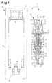
- Fig. 1
- eine Vorrichtung zum Herstellen eines Formteils aus Pulver,
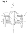
- Fig. 2
- einen Ausschnitt aus dem Werkzeug der Vorrichtung mit einem Kolben-Zylinder-System und einem erfindungsgemäßen Führungsmittel,
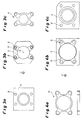
- Fig. 3a
- die Draufsicht auf einen Zylinder eines ersten Kolben-Zylinder-Systems der Vorrichtung,
- Fig. 3b
- die Draufsicht auf einen Kolben eines ersten Kolben-Zylinder-Systems der Vorrichtung,
- Fig. 3c
- die Draufsicht auf ein Trägerelement der Führungsmittel eines ersten Kolben-Zylinder-Systems,
- Fig. 4a
- die Draufsicht auf ein Trägerelement der Führungsmittel eines zweiten Kolben-Zylinder-Systems,
- Fig. 4b
- die Draufsicht auf einen Kolben eines zweiten Kolben-Zylinder-Systems der Vorrichtung und
- Fig. 4c
- die Draufsicht auf ein Trägerelement der Führungsmittel eines zweiten Kolben-Zylinder-Systems.
- In Fig. 1 ist eine Vorrichtung 1 zum Herstellen eines Formteils dargestellt, mit der Metallpulver 12 zu einem Formteil gepresst werden kann. Es sei angemerkt, dass die Erfindung nicht nur für die Verarbeitung von Pulver tauglich ist. Häufig wird ein bereits vorgeformter Pressling in einem weiteren Schritt nachgepresst, insbesondere beim abschließenden Pressen mit höheren Drücken.
- Die Vorrichtung 1 besteht im wesentlichen aus einem Werkzeug 2, das in eine Pressvorrichtung 3 eingesetzt werden kann. Die Pressvorrichtung 3 hat einen Maschinenrahmen 13 mit einer oberen Traverse 14 und einer unteren Traverse 15. An der oberen Traverse 14 ist ein Oberkolben 16 in einem Zylinder angeordnet, mit dem eine Presskraft nach unten ausgeübt werden kann. Die untere Traverse 15 trägt einen Unterkolben 17, mit dem eine Presskraft nach oben erzeugt werden kann.
- Das Werkzeug 2 weist eine Matrize 18 auf, die das Pulver 12 aufnimmt. Um eine gewünschte Formteilkontur herzustellen, ist eine Anzahl konzentrisch zueinander angeordnete stempelartige Kolben 5 vorgesehen, die in jeweiligen Zylindern 4 angeordnet sind und relativ zu diesen gesteuert bzw. geregelt verfahren werden können. Je ein Kolben 5 bildet zusammen mit dem diesen aufnehmenden Zylinder 4 ein Kolben-Zylinder-System, wie es als solches vorbekannt ist. Alle Kolben 5 bzw. Zylinder 4 sind im Ausführungsbeispiel um eine Zentralachse 6 herum konzentrisch angeordnet. Durch Betätigung der jeweiligen Kolben-Zylinder-Systeme 4, 5 kann eine Verfahrbewegung in Verfahrrichtung V (entspricht vorliegend der vertikalen Richtung) bewerkstelligt werden. Nur am Rande erwähnt seien Stempel 19 und 20, die durch den Oberkolben 16 betätigt werden, sowie ein Füller 21 für die Beschickung der Matrize 18 mit Pulver 12.
- Um eine kippfreie Führung des Kolbens 5 relativ zum Zylinder 4 auch bei unsymmetrischen Formteilen sicherzustellen und ferner eine relative Drehung zwischen Kolben 5 und Zylinder 4 um die Zentralachse 6 zu verhindern, ist eine Ausgestaltung vorgesehen, wie sie schematisch aus Fig. 2 hervorgeht.
- Zwischen Kolben 5 und Zylinder 4 ist ein Führungsmittel 7 vorgesehen, das Kippen verhindert und Verdrehen ausschließt. Hierzu ist am Kolben 5 ein plattenförmiges Trägerelement 11 befestigt, an dem wiederum vier Stangen 9 mit kreisförmigem Querschnitt fest angeordnet sind. Die Stangen 9 sind in Führungen 10 im Zylinder 4 in Verfahrrichtung V verschieblich angeordnet. Die Führungen können als eng tolerierte Gleitbuchsen ausgebildet sein, die sicherstellen, dass bei der Verschiebung des Kolbens 5 relativ zum Zylinder 4 in Verfahrrichtung V ein hoher Grad an Parallelität beider Elemente 4, 5 aufrechterhalten wird. Namentlich sollen Kippmomente M, die senkrecht zur Verfahrrichtung V wirken, keinen Einfluss auf die Parallelität zwischen Kolben 5 und Zylinder 4 haben.
- Die Stangen 9 sind so positioniert, dass ihre Achse 8 in einem (radialen) Abstand a von der Zentralachse 6 liegt.
- Wie in den Figuren 3 bzw. 4 für zwei Kolben-Zylinder-Systeme 4, 5 des Werkzeugs 2 gesehen werden kann, sind vorliegend vier Stangen 9 angeordnet, die zu zwei aufeinander senkrecht stehenden Symmetrieebenen spiegelbildlich positioniert sind. Die Stangen 9 werden von den jeweiligen Trägerelementen 11 gehalten, die an den Kolben 5 festgelegt sind. Zu dem in Fig. 4a skizzierten Trägerelement 11 ist auch der Schnitt in der Seitenansicht skizziert, um die Ausgestaltung des Elements zu illustrieren.
- Das Einfügen der Hauptführungsstangen in den Adapter (Werkzeug) ermöglicht es also, außermittige Kräfte besser als bisher aufzunehmen, da die Führungsstangen aufgrund ihrer Steifigkeit und ihrer Positionierung im Adapter (Werkzeug) Drehmomente und Seitenkräfte besser aufnehmen und übertragen können, als es bei der vorbekannten Lösung der Fall ist. Dort sind zumeist die Kolben mit Führungsbändern geführt, die nicht die Leistungsfähigkeit haben, wie die Ausgestaltung nach der Erfindung.
-
- 1
- Vorrichtung zum Herstellen eines Formteils
- 2
- Werkzeug
- 3
- Pressvorrichtung
- 4
- Zylinder
- 5
- Kolben
- 4, 5
- Kolben-Zylinder-System
- 6
- Zentralachse
- 7
- Führungsmittel
- 8
- Achse des Führungsmittels
- 9
- Stange
- 10
- Führung
- 11
- Trägerelement
- 12
- Metallpulver
- 13
- Maschinenrahmen
- 14
- obere Traverse
- 15
- untere Traverse
- 16
- Oberkolben
- 17
- Unterkolben
- 18
- Matrize
- 19
- Stempel
- 20
- Stempel
- 21
- Füller
- V
- Verfahrrichtung
- a
- Abstand
- M
- Kippmoment
Claims (9)
- Vorrichtung (1) zum Herstellen eines Formteils aus Pulver, insbesondere aus Metallpulver, aus einem ein Pulver enthaltenden, teigigen Material, aus einem ein Pulver enthaltenden, fließfähigen Material oder aus vorgepresstem Material, die ein Werkzeug (2) aufweist, auf das bei der Herstellung des Formteils von einer Pressvorrichtung (3) eine Druckkraft ausgeübt wird, wobei das Werkzeug (2) zur Erzeugung einer gewünschten Formteilkontur mindestens ein Kolben-Zylinder-System (4, 5) mit einer Zentralachse (6) aufweist, das einen hydraulisch relativ zu einem Zylinder (4) in eine Verfahrrichtung (V) bewegbaren Kolben (5) hat,
gekennzeichnet durch
ein Führungsmittel (7), das zumindest den Kolben (5) relativ zu dem Zylinder (4) in Verfahrrichtung (V) des Kolben-Zylinder-Systems (4, 5) führt, wobei sich das Führungsmittel (7) in Verfahrrichtung (V) entlang einer Achse (8) erstreckt, die von der Zentralachse (6) beabstandet (a) ist, wobei das Werkzeug (2) als auswechselbarer Adapter in der Pressvorrichtung (3) ausgebildet ist. - Vorrichtung nach Anspruch 1,
dadurch gekennzeichnet,
dass das Führungsmittel (7) zur Aufnahme eines Kippmoments (M) zwischen dem Zylinder (4) und dem Kolben (5) geeignet ist, wobei das Kippmoment (M) senkrecht zur Zentralachse (6) wirkt. - Vorrichtung nach Anspruch 1 oder 2,
dadurch gekennzeichnet,
dass das Führungsmittel (7) mindestens eine Stange (9) aufweist, die am Kolben (5) oder am Zylinder (4) fest angeordnet ist und die in einer Führung (10) im Zylinder (4) oder im Kolben (5) geführt ist. - Vorrichtung nach Anspruch 3,
dadurch gekennzeichnet,
dass mehrere Stangen (9) am Kolben (5) oder am Zylinder (4) angeordnet sind. - Vorrichtung nach Anspruch 4,
dadurch gekennzeichnet,
dass vier Stangen (9) am Kolben (5) oder am Zylinder (4) angeordnet sind. - Vorrichtung nach einem der Ansprüche 3 bis 5,
dadurch gekennzeichnet,
dass die Stange (9) an einem Trägerelement (11) befestigt ist, die am Kolben (5) oder am Zylinder (4) festgelegt ist. - Vorrichtung nach einem der Ansprüche 1 bis 6,
dadurch gekennzeichnet,
dass eine Anzahl Kolben-Zylinder-Systeme (4, 5) entlang der Zentralachse (6) angeordnet ist. - Vorrichtung nach Anspruch 7,
dadurch gekennzeichnet,
dass die Kolben (5) konzentrisch angeordnet sind und mindestens zwei Kolben (5) an zugewandten Mantelflächen aneinander liegen. - Vorrichtung nach Anspruch 7 oder 8,
dadurch gekennzeichnet,
dass das Führungsmittel (7) mehrere Kolben (5) und/oder Zylinder (4) relativ zueinander führt.
Applications Claiming Priority (1)
| Application Number | Priority Date | Filing Date | Title |
|---|---|---|---|
| DE102005044759A DE102005044759B4 (de) | 2005-09-20 | 2005-09-20 | Vorrichtung zum Herstellen eines Formteils |
Publications (3)
| Publication Number | Publication Date |
|---|---|
| EP1764173A2 true EP1764173A2 (de) | 2007-03-21 |
| EP1764173A3 EP1764173A3 (de) | 2008-07-02 |
| EP1764173B1 EP1764173B1 (de) | 2010-09-22 |
Family
ID=37672200
Family Applications (1)
| Application Number | Title | Priority Date | Filing Date |
|---|---|---|---|
| EP06013880A Active EP1764173B1 (de) | 2005-09-20 | 2006-07-04 | Vorrichtung zum Herstellen eines Formteils |
Country Status (5)
| Country | Link |
|---|---|
| US (1) | US20070062248A1 (de) |
| EP (1) | EP1764173B1 (de) |
| JP (1) | JP2007083308A (de) |
| AT (1) | ATE482041T1 (de) |
| DE (2) | DE102005044759B4 (de) |
Cited By (6)
| Publication number | Priority date | Publication date | Assignee | Title |
|---|---|---|---|---|
| WO2016124498A1 (de) * | 2015-02-02 | 2016-08-11 | Gkn Sinter Metals Engineering Gmbh | Gestaltoptimierte pm-werkzeugkomponenten unter verwendung von verbindungstechnologie |
| WO2016124497A1 (de) * | 2015-02-02 | 2016-08-11 | Gkn Sinter Metals Engineering Gmbh | Pulverpresse mit kegeligem unterstempel, verfahren zum betrieb einer pulverpresse, pressling hergestellt mit einer pulverpresse, unterstempel einer pulverpresse und computerprogrammprodukt zum verfahren von unterstempeln einer presse |
| WO2016124511A1 (de) * | 2015-02-04 | 2016-08-11 | Gkn Sinter Metals Engineering Gmbh | Pulverpresse mit kegeligem unterbau |
| CN108637244A (zh) * | 2018-04-12 | 2018-10-12 | 海宁金瑞金属制品有限公司 | 粉末冶金的成型模具 |
| EP3530448A1 (de) * | 2018-02-26 | 2019-08-28 | Osterwalder AG | Presseneinrichtung für eine pulverpresse und ein werkzeugwechselsystem |
| NL2028552B1 (en) * | 2021-06-25 | 2023-01-02 | Boschman Tech Bv | Component Processing Apparatus and Method Allowing to Selectively Apply Force to a Component Processed |
Families Citing this family (2)
| Publication number | Priority date | Publication date | Assignee | Title |
|---|---|---|---|---|
| DE102014003726A1 (de) * | 2014-03-18 | 2015-09-24 | Gkn Sinter Metals Engineering Gmbh | Presse zum Herstellen maßhaltiger Grünlinge und Verfahren zum Herstellen |
| DE102017114455B3 (de) * | 2017-06-29 | 2018-10-31 | Gkn Sinter Metals Engineering Gmbh | Ebenenplatte eines Pressenwerkzeugs |
Citations (1)
| Publication number | Priority date | Publication date | Assignee | Title |
|---|---|---|---|---|
| US5498147A (en) | 1990-08-10 | 1996-03-12 | Yoshizuka Seiki Co., Ltd. | Powder molding press |
Family Cites Families (7)
| Publication number | Priority date | Publication date | Assignee | Title |
|---|---|---|---|---|
| US2499980A (en) * | 1944-01-07 | 1950-03-07 | Stokes Machine Co | Press for molding annular stepped articles |
| DE3142126A1 (de) * | 1981-10-23 | 1983-05-11 | Dorst-Keramikmaschinen-Bau Otto Dorst U. Dipl.-Ing. Walter Schlegel, 8113 Kochel | "presse zum herstellen masshaltiger presslinge aus pulverfoermigem material" |
| DE3909757A1 (de) * | 1989-03-23 | 1990-09-27 | Dorst Masch & Anlagen | Presse mit einem in die presse einsetzbaren werkzeuggestell |
| DE9203546U1 (de) * | 1992-03-17 | 1993-07-22 | Komage - Gellner & Co. Maschinenfabrik KG, 54427 Kell | Vorrichtung zum Pressen von Formteilen aus einer feinkörnigen Masse |
| JPH0818158B2 (ja) * | 1993-06-29 | 1996-02-28 | 株式会社ヨシツカ精機 | 粉末成形プレス |
| JP2000015493A (ja) * | 1998-06-30 | 2000-01-18 | Aisin Seiki Co Ltd | 粉末成形機 |
| JP4714334B2 (ja) * | 2000-11-21 | 2011-06-29 | 株式会社ヨシツカ精機 | 粉末成形プレスのパンチ接続構造および接続方法 |
-
2005
- 2005-09-20 DE DE102005044759A patent/DE102005044759B4/de not_active Expired - Lifetime
-
2006
- 2006-07-04 EP EP06013880A patent/EP1764173B1/de active Active
- 2006-07-04 DE DE502006007915T patent/DE502006007915D1/de active Active
- 2006-07-04 AT AT06013880T patent/ATE482041T1/de active
- 2006-09-12 US US11/519,528 patent/US20070062248A1/en not_active Abandoned
- 2006-09-19 JP JP2006252813A patent/JP2007083308A/ja active Pending
Patent Citations (1)
| Publication number | Priority date | Publication date | Assignee | Title |
|---|---|---|---|---|
| US5498147A (en) | 1990-08-10 | 1996-03-12 | Yoshizuka Seiki Co., Ltd. | Powder molding press |
Cited By (15)
| Publication number | Priority date | Publication date | Assignee | Title |
|---|---|---|---|---|
| CN107427916B (zh) * | 2015-02-02 | 2020-09-29 | 吉凯恩粉末冶金工程有限公司 | 粉末压制机、其运行方法以及其计算机程序产品的存储介质 |
| WO2016124498A1 (de) * | 2015-02-02 | 2016-08-11 | Gkn Sinter Metals Engineering Gmbh | Gestaltoptimierte pm-werkzeugkomponenten unter verwendung von verbindungstechnologie |
| CN107427916A (zh) * | 2015-02-02 | 2017-12-01 | 吉凯恩粉末冶金工程有限公司 | 带有锥式的下冲模的粉末压制机、用于运行粉末压制机的方法、以粉末压制机制造的压制品、粉末压制机的下冲模和用于使压制机的下冲模移动的计算机程序产品 |
| CN107428105A (zh) * | 2015-02-02 | 2017-12-01 | 吉凯恩粉末冶金工程有限公司 | 在使用连接技术下的形状优化的pm工具构件 |
| US20180015680A1 (en) * | 2015-02-02 | 2018-01-18 | Gkn Sinter Metals Engineering Gmbh | Shape-Optimized PM Tool Components Using Connection Technology |
| WO2016124497A1 (de) * | 2015-02-02 | 2016-08-11 | Gkn Sinter Metals Engineering Gmbh | Pulverpresse mit kegeligem unterstempel, verfahren zum betrieb einer pulverpresse, pressling hergestellt mit einer pulverpresse, unterstempel einer pulverpresse und computerprogrammprodukt zum verfahren von unterstempeln einer presse |
| US11007744B2 (en) * | 2015-02-02 | 2021-05-18 | Gkn Sinter Metals Engineering Gmbh | Shape-optimized PM tool components using connection technology |
| WO2016124511A1 (de) * | 2015-02-04 | 2016-08-11 | Gkn Sinter Metals Engineering Gmbh | Pulverpresse mit kegeligem unterbau |
| US11103924B2 (en) | 2015-02-04 | 2021-08-31 | Gkn Sinter Metals Engineering Gmbh | Powder press having a cone-shaped substructure |
| CN111819072A (zh) * | 2018-02-26 | 2020-10-23 | 奥斯瓦尔德股份公司 | 用于粉末压机的压制设备以及工具更换系统 |
| EP3530448A1 (de) * | 2018-02-26 | 2019-08-28 | Osterwalder AG | Presseneinrichtung für eine pulverpresse und ein werkzeugwechselsystem |
| WO2019162510A1 (de) * | 2018-02-26 | 2019-08-29 | Osterwalder Ag | Presseneinrichtung für eine pulverpresse und ein werkzeugwechselsystem |
| US12097679B2 (en) | 2018-02-26 | 2024-09-24 | Osterwalder Ag | Press device for a powder press and a tool changing system |
| CN108637244A (zh) * | 2018-04-12 | 2018-10-12 | 海宁金瑞金属制品有限公司 | 粉末冶金的成型模具 |
| NL2028552B1 (en) * | 2021-06-25 | 2023-01-02 | Boschman Tech Bv | Component Processing Apparatus and Method Allowing to Selectively Apply Force to a Component Processed |
Also Published As
| Publication number | Publication date |
|---|---|
| JP2007083308A (ja) | 2007-04-05 |
| DE102005044759A1 (de) | 2007-04-05 |
| DE102005044759B4 (de) | 2007-07-12 |
| US20070062248A1 (en) | 2007-03-22 |
| ATE482041T1 (de) | 2010-10-15 |
| DE502006007915D1 (de) | 2010-11-04 |
| EP1764173B1 (de) | 2010-09-22 |
| EP1764173A3 (de) | 2008-07-02 |
Similar Documents
| Publication | Publication Date | Title |
|---|---|---|
| EP2103423B1 (de) | Pulverpresse zur Herstellung eines Presslings aus Metallpulver | |
| DE2604648C2 (de) | Rundlaufpresse | |
| DE69623567T2 (de) | Verfahren und Vorrichtung zur Herstellung von Pulverpresslingen | |
| EP0679503B1 (de) | Verfahren zur Herstellung von Presslingen aus pulverförmigem Material sowie entsprechende Presse | |
| EP4076881B1 (de) | Vorrichtung zur herstellung von betonsteinen | |
| DE3142126A1 (de) | "presse zum herstellen masshaltiger presslinge aus pulverfoermigem material" | |
| DE3036533A1 (de) | Presse zur herstellung von formkoerpern aus pulver | |
| EP0473769A1 (de) | Vorrichtung zur herstellung von tuben. | |
| DE2801225A1 (de) | Presswerkzeug zum pressen eines pulverfoermigen materials in ein geformtes werkstueck | |
| WO2016124511A1 (de) | Pulverpresse mit kegeligem unterbau | |
| EP2098317A1 (de) | Verfahren und Vorrichtung zum Herstellen eines Presslings aus Metallpulver | |
| EP2441573B1 (de) | Presse und Verfahren zur Herstellung eines Formlings aus pulverförmigem Material | |
| EP1764173B1 (de) | Vorrichtung zum Herstellen eines Formteils | |
| DE2224592A1 (de) | Doppelt wirkende Einkolben-Presse i zur Komprimierung von Pulver | |
| DE69502722T2 (de) | Dosiervorrichtung für eine tablettierpresse | |
| DE69817482T2 (de) | Verfahren zum herstellen von keramischen fliesen , einschliesslich fliesen mit grossen abmessungen und vorrichtung zum durchführen des verfahrens | |
| DE2906858A1 (de) | Pressgussvorrichtung | |
| DE2033106A1 (de) | Stauch oder Schmiedepresse | |
| EP3075505B1 (de) | Vorrichtung zur herstellung von betonformteilen | |
| EP0220634A2 (de) | Schliesseinheit für Formwerkzeuge, insbesondere solchen für die Herstellung von Polyurethan-Formteilen | |
| DE102015103829A1 (de) | Vorrichtung zur Herstellung von Betonformteilen in einer Formmaschine | |
| DE3304576A1 (de) | Verfahren und vorrichtung zum herstellen von tiefen kegeligen oder zylindrischen keramischen hohlkoerpern aus pulverfoermiger oder granulatartiger pressmasse durch isostatisches pressen | |
| DE102023123181A1 (de) | Vorrichtung zum Herstellen von Formlingen, insbesondere Steinformlinge für Mauerwerksteine und Verfahren zum Ändern eines Formats von herzustellenden Formlingen | |
| DE102005027296B3 (de) | Vorrichtung zum Herstellen eines Formteils aus Pulver | |
| DE102005027032B4 (de) | Vorrichtung zum Herstellen eines Formteils |
Legal Events
| Date | Code | Title | Description |
|---|---|---|---|
| PUAI | Public reference made under article 153(3) epc to a published international application that has entered the european phase |
Free format text: ORIGINAL CODE: 0009012 |
|
| AK | Designated contracting states |
Kind code of ref document: A2 Designated state(s): AT BE BG CH CY CZ DE DK EE ES FI FR GB GR HU IE IS IT LI LT LU LV MC NL PL PT RO SE SI SK TR |
|
| AX | Request for extension of the european patent |
Extension state: AL BA HR MK YU |
|
| PUAL | Search report despatched |
Free format text: ORIGINAL CODE: 0009013 |
|
| AK | Designated contracting states |
Kind code of ref document: A3 Designated state(s): AT BE BG CH CY CZ DE DK EE ES FI FR GB GR HU IE IS IT LI LT LU LV MC NL PL PT RO SE SI SK TR |
|
| AX | Request for extension of the european patent |
Extension state: AL BA HR MK RS |
|
| 17P | Request for examination filed |
Effective date: 20081206 |
|
| 17Q | First examination report despatched |
Effective date: 20090206 |
|
| AKX | Designation fees paid |
Designated state(s): AT BE BG CH CY CZ DE DK EE ES FI FR GB GR HU IE IS IT LI LT LU LV MC NL PL PT RO SE SI SK TR |
|
| GRAP | Despatch of communication of intention to grant a patent |
Free format text: ORIGINAL CODE: EPIDOSNIGR1 |
|
| GRAS | Grant fee paid |
Free format text: ORIGINAL CODE: EPIDOSNIGR3 |
|
| GRAA | (expected) grant |
Free format text: ORIGINAL CODE: 0009210 |
|
| AK | Designated contracting states |
Kind code of ref document: B1 Designated state(s): AT BE BG CH CY CZ DE DK EE ES FI FR GB GR HU IE IS IT LI LT LU LV MC NL PL PT RO SE SI SK TR |
|
| REG | Reference to a national code |
Ref country code: GB Ref legal event code: FG4D Free format text: NOT ENGLISH |
|
| REG | Reference to a national code |
Ref country code: CH Ref legal event code: EP |
|
| REG | Reference to a national code |
Ref country code: CH Ref legal event code: NV Representative=s name: SCHMAUDER & PARTNER AG PATENT- UND MARKENANWAELTE |
|
| REG | Reference to a national code |
Ref country code: IE Ref legal event code: FG4D Free format text: LANGUAGE OF EP DOCUMENT: GERMAN |
|
| REF | Corresponds to: |
Ref document number: 502006007915 Country of ref document: DE Date of ref document: 20101104 Kind code of ref document: P |
|
| PG25 | Lapsed in a contracting state [announced via postgrant information from national office to epo] |
Ref country code: LT Free format text: LAPSE BECAUSE OF FAILURE TO SUBMIT A TRANSLATION OF THE DESCRIPTION OR TO PAY THE FEE WITHIN THE PRESCRIBED TIME-LIMIT Effective date: 20100922 Ref country code: FI Free format text: LAPSE BECAUSE OF FAILURE TO SUBMIT A TRANSLATION OF THE DESCRIPTION OR TO PAY THE FEE WITHIN THE PRESCRIBED TIME-LIMIT Effective date: 20100922 |
|
| REG | Reference to a national code |
Ref country code: NL Ref legal event code: VDEP Effective date: 20100922 |
|
| LTIE | Lt: invalidation of european patent or patent extension |
Effective date: 20100922 |
|
| PG25 | Lapsed in a contracting state [announced via postgrant information from national office to epo] |
Ref country code: SI Free format text: LAPSE BECAUSE OF FAILURE TO SUBMIT A TRANSLATION OF THE DESCRIPTION OR TO PAY THE FEE WITHIN THE PRESCRIBED TIME-LIMIT Effective date: 20100922 Ref country code: PL Free format text: LAPSE BECAUSE OF FAILURE TO SUBMIT A TRANSLATION OF THE DESCRIPTION OR TO PAY THE FEE WITHIN THE PRESCRIBED TIME-LIMIT Effective date: 20100922 |
|
| PG25 | Lapsed in a contracting state [announced via postgrant information from national office to epo] |
Ref country code: SE Free format text: LAPSE BECAUSE OF FAILURE TO SUBMIT A TRANSLATION OF THE DESCRIPTION OR TO PAY THE FEE WITHIN THE PRESCRIBED TIME-LIMIT Effective date: 20100922 Ref country code: GR Free format text: LAPSE BECAUSE OF FAILURE TO SUBMIT A TRANSLATION OF THE DESCRIPTION OR TO PAY THE FEE WITHIN THE PRESCRIBED TIME-LIMIT Effective date: 20101223 Ref country code: LV Free format text: LAPSE BECAUSE OF FAILURE TO SUBMIT A TRANSLATION OF THE DESCRIPTION OR TO PAY THE FEE WITHIN THE PRESCRIBED TIME-LIMIT Effective date: 20100922 |
|
| REG | Reference to a national code |
Ref country code: IE Ref legal event code: FD4D |
|
| PG25 | Lapsed in a contracting state [announced via postgrant information from national office to epo] |
Ref country code: IE Free format text: LAPSE BECAUSE OF FAILURE TO SUBMIT A TRANSLATION OF THE DESCRIPTION OR TO PAY THE FEE WITHIN THE PRESCRIBED TIME-LIMIT Effective date: 20100922 |
|
| PG25 | Lapsed in a contracting state [announced via postgrant information from national office to epo] |
Ref country code: IT Free format text: LAPSE BECAUSE OF FAILURE TO SUBMIT A TRANSLATION OF THE DESCRIPTION OR TO PAY THE FEE WITHIN THE PRESCRIBED TIME-LIMIT Effective date: 20100922 Ref country code: SK Free format text: LAPSE BECAUSE OF FAILURE TO SUBMIT A TRANSLATION OF THE DESCRIPTION OR TO PAY THE FEE WITHIN THE PRESCRIBED TIME-LIMIT Effective date: 20100922 Ref country code: PT Free format text: LAPSE BECAUSE OF FAILURE TO SUBMIT A TRANSLATION OF THE DESCRIPTION OR TO PAY THE FEE WITHIN THE PRESCRIBED TIME-LIMIT Effective date: 20110124 Ref country code: EE Free format text: LAPSE BECAUSE OF FAILURE TO SUBMIT A TRANSLATION OF THE DESCRIPTION OR TO PAY THE FEE WITHIN THE PRESCRIBED TIME-LIMIT Effective date: 20100922 Ref country code: CZ Free format text: LAPSE BECAUSE OF FAILURE TO SUBMIT A TRANSLATION OF THE DESCRIPTION OR TO PAY THE FEE WITHIN THE PRESCRIBED TIME-LIMIT Effective date: 20100922 Ref country code: RO Free format text: LAPSE BECAUSE OF FAILURE TO SUBMIT A TRANSLATION OF THE DESCRIPTION OR TO PAY THE FEE WITHIN THE PRESCRIBED TIME-LIMIT Effective date: 20100922 Ref country code: NL Free format text: LAPSE BECAUSE OF FAILURE TO SUBMIT A TRANSLATION OF THE DESCRIPTION OR TO PAY THE FEE WITHIN THE PRESCRIBED TIME-LIMIT Effective date: 20100922 Ref country code: IS Free format text: LAPSE BECAUSE OF FAILURE TO SUBMIT A TRANSLATION OF THE DESCRIPTION OR TO PAY THE FEE WITHIN THE PRESCRIBED TIME-LIMIT Effective date: 20110122 |
|
| PG25 | Lapsed in a contracting state [announced via postgrant information from national office to epo] |
Ref country code: ES Free format text: LAPSE BECAUSE OF FAILURE TO SUBMIT A TRANSLATION OF THE DESCRIPTION OR TO PAY THE FEE WITHIN THE PRESCRIBED TIME-LIMIT Effective date: 20110102 |
|
| PLBE | No opposition filed within time limit |
Free format text: ORIGINAL CODE: 0009261 |
|
| STAA | Information on the status of an ep patent application or granted ep patent |
Free format text: STATUS: NO OPPOSITION FILED WITHIN TIME LIMIT |
|
| 26N | No opposition filed |
Effective date: 20110623 |
|
| PG25 | Lapsed in a contracting state [announced via postgrant information from national office to epo] |
Ref country code: DK Free format text: LAPSE BECAUSE OF FAILURE TO SUBMIT A TRANSLATION OF THE DESCRIPTION OR TO PAY THE FEE WITHIN THE PRESCRIBED TIME-LIMIT Effective date: 20100922 |
|
| REG | Reference to a national code |
Ref country code: DE Ref legal event code: R097 Ref document number: 502006007915 Country of ref document: DE Effective date: 20110623 |
|
| BERE | Be: lapsed |
Owner name: SMS MEER G.M.B.H. Effective date: 20110731 |
|
| PG25 | Lapsed in a contracting state [announced via postgrant information from national office to epo] |
Ref country code: MC Free format text: LAPSE BECAUSE OF NON-PAYMENT OF DUE FEES Effective date: 20110731 |
|
| GBPC | Gb: european patent ceased through non-payment of renewal fee |
Effective date: 20110704 |
|
| REG | Reference to a national code |
Ref country code: FR Ref legal event code: ST Effective date: 20120330 |
|
| PG25 | Lapsed in a contracting state [announced via postgrant information from national office to epo] |
Ref country code: FR Free format text: LAPSE BECAUSE OF NON-PAYMENT OF DUE FEES Effective date: 20110801 Ref country code: BE Free format text: LAPSE BECAUSE OF NON-PAYMENT OF DUE FEES Effective date: 20110731 |
|
| PG25 | Lapsed in a contracting state [announced via postgrant information from national office to epo] |
Ref country code: GB Free format text: LAPSE BECAUSE OF NON-PAYMENT OF DUE FEES Effective date: 20110704 |
|
| PG25 | Lapsed in a contracting state [announced via postgrant information from national office to epo] |
Ref country code: CY Free format text: LAPSE BECAUSE OF EXPIRATION OF PROTECTION Effective date: 20100922 Ref country code: LU Free format text: LAPSE BECAUSE OF NON-PAYMENT OF DUE FEES Effective date: 20110704 |
|
| PG25 | Lapsed in a contracting state [announced via postgrant information from national office to epo] |
Ref country code: BG Free format text: LAPSE BECAUSE OF FAILURE TO SUBMIT A TRANSLATION OF THE DESCRIPTION OR TO PAY THE FEE WITHIN THE PRESCRIBED TIME-LIMIT Effective date: 20101222 Ref country code: TR Free format text: LAPSE BECAUSE OF FAILURE TO SUBMIT A TRANSLATION OF THE DESCRIPTION OR TO PAY THE FEE WITHIN THE PRESCRIBED TIME-LIMIT Effective date: 20100922 |
|
| PG25 | Lapsed in a contracting state [announced via postgrant information from national office to epo] |
Ref country code: HU Free format text: LAPSE BECAUSE OF FAILURE TO SUBMIT A TRANSLATION OF THE DESCRIPTION OR TO PAY THE FEE WITHIN THE PRESCRIBED TIME-LIMIT Effective date: 20100922 |
|
| REG | Reference to a national code |
Ref country code: DE Ref legal event code: R082 Ref document number: 502006007915 Country of ref document: DE Representative=s name: HEMMERICH & KOLLEGEN PATENTANWAELTE, DE Ref country code: DE Ref legal event code: R082 Ref document number: 502006007915 Country of ref document: DE Representative=s name: HEMMERICH & KOLLEGEN, DE Ref country code: DE Ref legal event code: R081 Ref document number: 502006007915 Country of ref document: DE Owner name: SMS GROUP GMBH, DE Free format text: FORMER OWNER: SMS MEER GMBH, 41069 MOENCHENGLADBACH, DE |
|
| P01 | Opt-out of the competence of the unified patent court (upc) registered |
Effective date: 20230707 |
|
| PGFP | Annual fee paid to national office [announced via postgrant information from national office to epo] |
Ref country code: CH Payment date: 20230801 Year of fee payment: 18 Ref country code: AT Payment date: 20230720 Year of fee payment: 18 |
|
| PGFP | Annual fee paid to national office [announced via postgrant information from national office to epo] |
Ref country code: DE Payment date: 20230719 Year of fee payment: 18 |
|
| REG | Reference to a national code |
Ref country code: DE Ref legal event code: R119 Ref document number: 502006007915 Country of ref document: DE |
|
| REG | Reference to a national code |
Ref country code: CH Ref legal event code: PL |
|
| REG | Reference to a national code |
Ref country code: AT Ref legal event code: MM01 Ref document number: 482041 Country of ref document: AT Kind code of ref document: T Effective date: 20240704 |
|
| PG25 | Lapsed in a contracting state [announced via postgrant information from national office to epo] |
Ref country code: DE Free format text: LAPSE BECAUSE OF NON-PAYMENT OF DUE FEES Effective date: 20250201 |
|
| PG25 | Lapsed in a contracting state [announced via postgrant information from national office to epo] |
Ref country code: AT Free format text: LAPSE BECAUSE OF NON-PAYMENT OF DUE FEES Effective date: 20240704 Ref country code: CH Free format text: LAPSE BECAUSE OF NON-PAYMENT OF DUE FEES Effective date: 20240731 |