EP1760031A2 - Châssis inférieur de grue optimisé pour transport - Google Patents
Châssis inférieur de grue optimisé pour transport Download PDFInfo
- Publication number
- EP1760031A2 EP1760031A2 EP06014393A EP06014393A EP1760031A2 EP 1760031 A2 EP1760031 A2 EP 1760031A2 EP 06014393 A EP06014393 A EP 06014393A EP 06014393 A EP06014393 A EP 06014393A EP 1760031 A2 EP1760031 A2 EP 1760031A2
- Authority
- EP
- European Patent Office
- Prior art keywords
- crane
- support
- undercarriage
- support struts
- truck according
- Prior art date
- Legal status (The legal status is an assumption and is not a legal conclusion. Google has not performed a legal analysis and makes no representation as to the accuracy of the status listed.)
- Granted
Links
- 230000000284 resting effect Effects 0.000 claims 1
- 239000000969 carrier Substances 0.000 description 9
- 238000010276 construction Methods 0.000 description 5
- NJPPVKZQTLUDBO-UHFFFAOYSA-N novaluron Chemical compound C1=C(Cl)C(OC(F)(F)C(OC(F)(F)F)F)=CC=C1NC(=O)NC(=O)C1=C(F)C=CC=C1F NJPPVKZQTLUDBO-UHFFFAOYSA-N 0.000 description 4
- 239000011324 bead Substances 0.000 description 1
- 230000005540 biological transmission Effects 0.000 description 1
- 230000007613 environmental effect Effects 0.000 description 1
- 238000009434 installation Methods 0.000 description 1
Images


Classifications
-
- B—PERFORMING OPERATIONS; TRANSPORTING
- B66—HOISTING; LIFTING; HAULING
- B66C—CRANES; LOAD-ENGAGING ELEMENTS OR DEVICES FOR CRANES, CAPSTANS, WINCHES, OR TACKLES
- B66C23/00—Cranes comprising essentially a beam, boom, or triangular structure acting as a cantilever and mounted for translatory of swinging movements in vertical or horizontal planes or a combination of such movements, e.g. jib-cranes, derricks, tower cranes
- B66C23/62—Constructional features or details
- B66C23/72—Counterweights or supports for balancing lifting couples
- B66C23/78—Supports, e.g. outriggers, for mobile cranes
- B66C23/80—Supports, e.g. outriggers, for mobile cranes hydraulically actuated
-
- B—PERFORMING OPERATIONS; TRANSPORTING
- B62—LAND VEHICLES FOR TRAVELLING OTHERWISE THAN ON RAILS
- B62D—MOTOR VEHICLES; TRAILERS
- B62D55/00—Endless track vehicles
- B62D55/06—Endless track vehicles with tracks without ground wheels
- B62D55/062—Tracked vehicles of great dimensions adapted for moving bulky loads or gear
-
- B—PERFORMING OPERATIONS; TRANSPORTING
- B66—HOISTING; LIFTING; HAULING
- B66C—CRANES; LOAD-ENGAGING ELEMENTS OR DEVICES FOR CRANES, CAPSTANS, WINCHES, OR TACKLES
- B66C23/00—Cranes comprising essentially a beam, boom, or triangular structure acting as a cantilever and mounted for translatory of swinging movements in vertical or horizontal planes or a combination of such movements, e.g. jib-cranes, derricks, tower cranes
- B66C23/62—Constructional features or details
Definitions
- the present invention relates to a transport-optimized crane undercarriage, which can be used in particular optionally in a so-called CC crane or a PC crane.
- the former crane variant is a so-called crawler crane.
- a crawler crane is characterized by the fact that it can be moved on caterpillars.
- the second crane variant is a so-called Pedestal Crane, in which the crane undercarriage is stationary on ground support beams.
- the support elements of such a crane ie the components on which the entire crane stands, are different.
- CC cranes are sometimes used, which can be moved by means of caterpillars.
- two opposing crawler supports are releasably attached to a crane undercarriage.
- a crane undercarriage or crane underframe on which a caterpillar support is detachably attachable via bolts on two opposite sides of the crane undercarriage.
- the middle part of the crane undercarriage is designed with four support struts, of which two each extend substantially horizontally on one side and two on the other side. At the ends of the support struts bearing surfaces are formed for bolting the crawler support.
- the support struts themselves are rigidly formed on the central part, which is designed for removably mounting a rotatable crane superstructure.
- a crane with four supporting struts extending from a crane undercarriage middle section and individually attached crawler carriers was manufactured by TAKRAF.
- the crane consists of a center piece, two cross members and four small crawler tracks.
- the center piece and the cross member are detachably connected together.
- the cross members are removed from the center piece.
- a crane undercarriage having a central portion adapted for detachably mounting a rotatable crane truck.
- several support struts are mounted pivotally mounted. This allows the support struts occupy a transport and at least one operating position, without incurring expensive assembly work.
- the support struts of this crane undercarriage according to the invention are designed so that it can be attached to the necessary for crane operation support elements.
- the support elements may be caterpillar carriers or, for the variant, a PC crane, ground support carriers.
- the pivoting of the support beams takes place in each case about a substantially vertical axis.
- the invention is based on the idea to create a crane undercarriage for the first time, which is optimized for transport, on the other hand requires less construction time. Due to the pivotal mounting of the support struts on the central part of the crane undercarriage transport on a conventional low loader is readily possible. In particular, a transport in compliance with road traffic regulations is feasible. In that the connections between the middle piece and the support struts are not detachable, but provided pivotally, the assumption of an operating position and thus the installation of the crane in a short time is possible. Due to the pivotable configuration of the support struts on the crane undercarriage middle part, it is also readily possible, for example, to provide an optimized operating position both when attaching crawler carriers and when attaching Bodenabstützmayn.
- the distance of the support struts from each other can be optimized so that a large support surface is achieved.
- the distances of the ends of the support struts are as far away from each other, so that a large "span or support base" and thus a large support surface can be achieved.
- an inventive crane undercarriage is provided as part of a CC crane, an optimized with regard to the track width of the beads position of the support struts is possible.
- the support struts can occupy several or different operating positions, in particular depending on the nature of the support elements. That Depending on whether the crane undercarriage according to the present invention is provided as part of a PC crane or a CC crane, the support struts can be optimally adapted to the respective application conditions, ie adopt the respective optimized operating position.
- the transport position is preferably the same, namely such that in each case a plurality of arms are pivoted on one side of the central part and the other arms or support struts on the other side, so that an elongate transport unit of central part and away from each other directed support struts, the optimal a low loader is transportable.
- a crane undercarriage may, but need not, be used both for a PC crane and a CC crane.
- An exemplary embodiment of the invention provides that a crane undercarriage according to the invention can be provided with both crawler carriers and Bodenabstützmien to be used once as a CC crane and once as a PC crane.
- the crane undercarriage according to the invention is instead provided with Bodenabstützzan in or on a pedestal foundation attached, for example, bolted.
- the pedestal foundation is in turn then, for example, in turn variable in height, whereby the entire crane can be raised.
- an inventive crane undercarriage with the support struts pivotally mounted on the central part is designed only to receive crawler supports, or is designed only to receive Bodenabstützmie.
- an inventive crane undercarriage is to be used only as part of a CC crane and in the other case as part of a PC crane.
- the crane undercarriage can be provided with both crawlers or crawler tracks as well as ground support beams, i. the respective support elements are releasably attached to the support struts and designed so that their detachable connections are identical to the support struts of the crane undercarriage.
- An exemplary embodiment of a crane undercarriage according to the invention provides that the middle part has an outer periphery, on which four pivot joints are formed, on each of which a support strut is pivotally mounted.
- This embodiment enables an optimal enlargement of the support surface with support struts located in the operating position.
- a further exemplary embodiment of a crane undercarriage according to the invention provides that the middle part comprises a substantially cup-shaped main body on which a rotary bearing unit is present concentric to the central axis of the main body. On this rotary bearing unit of the crane superstructure is rotatably mounted.
- the design of the rotary bearing unit is well known in the art and therefore need not be discussed further in detail here.
- the type of connection between outer carrier and support strut can be done in a manner customary in crane construction, in particular by bolting. However, it is also possible to screw such outer support to the respective ends of the support struts or otherwise secure. Of course, it must be ensured here that the type of connection allows the transmission of the not inconsiderable forces and moments.
- the invention also relates to a variable crane comprising a crane undercarriage according to the invention of the type described above and a set of caterpillars and / or a set Bodenabstützmie.
- the set of caterpillars is detachably mounted on the support struts of the crane undercarriage.
- the crane In the assembled state of the caterpillar set, the crane can be moved on the caterpillars.
- ground support beams are detachably mounted on the support trolleys of the crane undercarriage, the crane is a PC crane and rests on the ground support beams.
- On the crane is then still a crane superstructure removable mountable; this is rotatable in the mounted state relative to the crane truck.
- a crane which can be used both as a PC crane and as a CC crane is created, which is optimized for transport and also optimized in terms of the construction and dismantling time.
- the attachment of the caterpillars or the Bodenabstützraj can be done in a well-known manner, in particular by bolting etc.
- the crawler support and the Bodenabstützm at the points which are releasably connected to the support struts of the central part of the crane undercarriage, preferably identical, so that their mountability is given to the support struts.
- any hydraulic and / or pneumatic connections and / or electrical connections of the crawler support and the Bodenabst Reifenong are the same, so that they are connected to the respective connections to the support struts can be. This eliminates the need for separate connections for the crawler support and Bodenabstützmoi the center part or on the support struts.
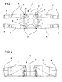
- the crane undercarriage 1 comprises a central part which forms a substantially pot-shaped basic body 2.
- This cup-shaped main body 2 is provided with a rotary bearing unit shown here only schematically, which allows a detachable attachment of a crane superstructure 40 shown only in FIG. 11 rotatable on the cup-shaped base body 2.
- a total of four pivot joints 3 are formed, on each of which a substantially horizontally or horizontally extending support strut 4 relative to the cup-shaped base body 2 are pivotally mounted.
- the pivot joints 3 are arranged at 90 ° intervals with respect to the central axis of the main body 2. It is of course also possible to provide 3 other angles between the pivot joints. For example, it is also possible to arrange the pivot joints 3 located on one side of a crane so that the angle enclosed between the two pivot joints 3 is greater than 90 °, for example 120 °. As a result, under certain circumstances a more optimized transport position can be achieved.
- a receiving device 5 is provided, which allows a removable attachment of Auflager electroden.
- the receiving device 5 may be formed for example by a Verbolzung, as is well known in the art.
- the main body 2 shows a part of the crane undercarriage 1 according to the invention, here in particular the pot-shaped basic body 2.
- the main body 2 has struts 7 reaching the pivot joints 3, which increase the rigidity of the crane undercarriage 1 and the forwarding of forces allowed on the support struts 4 and the support elements 10 and 20, which will be described later, in the ground.
- FIGS. 1 and 2 which is stored here for transport on a low loader 100. From this representation, in particular, the dimensions of such a crane undercarriage are clear.
- the cup-shaped base body 2 has a diameter of about 2 m, u. also 2.5-4 m and the support struts may for example have a length of about 2 m, or even 3-4 m.
- deviations of the dimensions mentioned above or below are possible. In particular, all intermediate values are possible.
- Fig. 1 take the support struts 4 an optimized transport position.
- the crane undercarriage 1 with the pivotal position of the support struts 4 shown in FIG. 1 is thus placed longitudinally on a low loader and transported to the next site.
- the support struts 4 are pivoted into the operating position shown in FIG. 4 and optionally locked in this operating position.
- a crawler support 10 is mounted on two support struts 4. It is of course also possible that a separate crawler support 10 is attached to each support strut 4, as it is known for example from the aforementioned TAKRAF MKZ 3000.
- the connection of the outer support 4 and the respective crawler support 10 is again by the known Verbolzung.
- the EP 0 736 480 B1 known bolting be used.
- the perspective view of the crane undercarriage according to FIG. 7 also shows, in particular, the connection points between the track carriers 10 and the support struts 4.
- each support strut 4 ground support beams 22, as shown schematically in FIG.
- bottom plates 24 via supports 25 at the ends of the support bracket 4 releasably or removably attached.
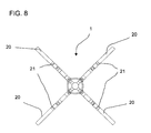
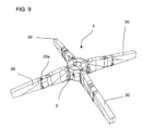
- FIGS. 8 and 9 show another exemplary embodiment of the present invention.
- outer support 20 is detachably mounted, at the outer ends turn then crawler support 10 or Bodenabstützmie 22 are mounted.
- the crane undercarriage 1 according to the present invention is shown in side view, and in particular here the ground support beams 22 can be seen, which are detachable at the outer ends of the outer supports 20 are attached.
- the perspective view of the crane undercarriage according to FIG. 9 also shows, in particular, the connection points between the support struts 4 and the outer supports or strut extensions 25.
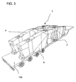
- FIG. 11 shows a variable crane according to the invention with crane undercarriage 1, on which a plurality of supporting struts 4 are mounted in a pivotable manner.
- a crane superstructure 40 is mounted with the driver's cab 45, which is rotatable in operation relative to the crane undercarriage 1.
- the crane is designed as a CC crane and, correspondingly, tracked carriers 10 are detachably mounted on the crane undercarriage 1 according to the invention.
- the crane superstructure 40 according to the invention has counterweights 46 and a lattice mast 42, which is guyed over a derrick mast 44.
Applications Claiming Priority (1)
| Application Number | Priority Date | Filing Date | Title |
|---|---|---|---|
| DE102005041255A DE102005041255A1 (de) | 2005-08-31 | 2005-08-31 | Transportoptimierter Kranunterwagen |
Publications (3)
| Publication Number | Publication Date |
|---|---|
| EP1760031A2 true EP1760031A2 (fr) | 2007-03-07 |
| EP1760031A3 EP1760031A3 (fr) | 2009-07-08 |
| EP1760031B1 EP1760031B1 (fr) | 2012-12-26 |
Family
ID=37429218
Family Applications (1)
| Application Number | Title | Priority Date | Filing Date |
|---|---|---|---|
| EP06014393A Active EP1760031B1 (fr) | 2005-08-31 | 2006-07-11 | Châssis inférieur de grue optimisé pour transport |
Country Status (5)
| Country | Link |
|---|---|
| US (1) | US20070045212A1 (fr) |
| EP (1) | EP1760031B1 (fr) |
| JP (1) | JP2007063022A (fr) |
| CN (1) | CN1923664B (fr) |
| DE (1) | DE102005041255A1 (fr) |
Families Citing this family (12)
| Publication number | Priority date | Publication date | Assignee | Title |
|---|---|---|---|---|
| CN102452616B (zh) * | 2010-10-20 | 2013-06-19 | 徐州重型机械有限公司 | 一种支腿支撑装置及移动式起重机 |
| CN102001585A (zh) * | 2010-12-21 | 2011-04-06 | 徐州重型机械有限公司 | 一种起重机及其车架 |
| CN102320331B (zh) * | 2011-06-15 | 2013-03-20 | 郑州新大方重工科技有限公司 | 一种行走车辆底盘 |
| PL3105164T3 (pl) | 2014-02-14 | 2018-03-30 | Palfinger Ag | Cokół żurawia dla żurawia ładunkowego |
| DE102015205008A1 (de) * | 2015-03-19 | 2016-09-22 | Terex Global Gmbh | Unterwagen für einen Fahrzeugkran sowie Fahrzeugkran mit einem derartigen Unterwagen |
| DE102015226314A1 (de) * | 2015-12-21 | 2017-06-22 | Terex Global Gmbh | Modularer Kran, Transporteinheit für einen modularen Kran und Verfahren zum Betreiben eines derartigen Krans |
| CN105883635B (zh) * | 2016-06-22 | 2017-09-29 | 中国铁道科学研究院运输及经济研究所 | 一种集装箱门式起重机的行走台车及车轮快速更换方法 |
| CN106395699A (zh) * | 2016-09-22 | 2017-02-15 | 特雷克斯(常州)机械有限公司 | 一种高空作业平台可伸缩行走车架 |
| CN106744376A (zh) * | 2017-02-27 | 2017-05-31 | 北汽福田汽车股份有限公司 | 起重吊臂支架和汽车起重机 |
| CN112499538B (zh) * | 2021-02-08 | 2021-04-20 | 山东广域科技有限责任公司 | 一种变电站运维用载人升降平台 |
| JP2022187518A (ja) * | 2021-06-08 | 2022-12-20 | コベルコ建機株式会社 | 移動式クレーンの下部走行体 |
| EP4328172A1 (fr) * | 2021-06-08 | 2024-02-28 | Kobelco Construction Machinery Co., Ltd. | Train de roulement de grue mobile |
Citations (1)
| Publication number | Priority date | Publication date | Assignee | Title |
|---|---|---|---|---|
| EP0736480B1 (fr) | 1991-09-20 | 2000-05-24 | Manitowoc Crane Group, Inc. | Connexion du chassis de base d'une grue aux chenilles de traction |
Family Cites Families (26)
| Publication number | Priority date | Publication date | Assignee | Title |
|---|---|---|---|---|
| US291481A (en) * | 1884-01-01 | Fire-escape and hook-and-ladder carriage | ||
| US1432378A (en) * | 1921-10-11 | 1922-10-17 | Bailly Armand | Traveling crane |
| US2914194A (en) * | 1957-08-21 | 1959-11-24 | American Hoist & Derrick Co | Outrigger construction for carrier mounted cranes |
| US3023913A (en) * | 1957-10-28 | 1962-03-06 | Talbert Construction Equipment | Mobile crane unit with demountable side frame |
| US3312291A (en) * | 1964-10-05 | 1967-04-04 | Raymond Int Inc | Derricks |
| US3385014A (en) * | 1964-10-05 | 1968-05-28 | Raymond Int Inc | Portable derricks |
| DE1231867B (de) * | 1965-04-29 | 1967-01-05 | Beteiligungs & Patentverw Gmbh | Schwerlast-Autokran |
| FR1594609A (fr) * | 1968-09-19 | 1970-06-08 | ||
| US3700115A (en) * | 1970-09-17 | 1972-10-24 | Koehring Co | Vehicle with variable width ground supports |
| US3929204A (en) * | 1975-01-22 | 1975-12-30 | Lawrence Hugh Newell | Trailer crane with outrigger to crawler conversion |
| US4000784A (en) * | 1975-04-24 | 1977-01-04 | The Manitowoc Company, Inc. | Demountable self-propelled crane transport assembly |
| JPS5378747U (fr) * | 1976-12-02 | 1978-06-30 | ||
| US4266679A (en) * | 1979-04-09 | 1981-05-12 | Harnischfeger Corporation | Convertible boom machine having modular bottom portion |
| US4397396A (en) * | 1980-11-07 | 1983-08-09 | Harnischfeger Corporation | Truck crane having an elongated main frame |
| US4387814A (en) * | 1981-09-08 | 1983-06-14 | The Manitowoc Company, Inc. | Traveling attachment for ring supported lift crane |
| US4496062A (en) * | 1983-03-07 | 1985-01-29 | Harnischfeger Corporation | Crane having stabilizing outriggers |
| US4624357A (en) * | 1984-06-25 | 1986-11-25 | Rotec Industries, Inc. | Vehicle-mounted extensible conveyor |
| DE3442319A1 (de) * | 1984-11-20 | 1986-06-26 | Wolfgang 2153 Neu Wulmstorf Schwarz | Verstellbarer unterwagen fuer kettenfahrwerke, durch mechanisches ausklappen der kettentraeger, mit eigenem antrieb |
| AT396097B (de) * | 1991-10-24 | 1993-05-25 | Eccon Eng Computer Consult | Chassis fuer raupenfahrwerke |
| JPH0789696A (ja) * | 1993-09-22 | 1995-04-04 | Nippon Sharyo Seizo Kaisha Ltd | 自走式クレーン車 |
| JPH0796869A (ja) * | 1993-09-29 | 1995-04-11 | Komatsu Ltd | クローラ式建設機械の下部走行体 |
| US6308958B1 (en) * | 1999-10-12 | 2001-10-30 | General Electric Company | Arrangement and method for radially positioning a turbine brush seal |
| DE10000814A1 (de) * | 2000-01-12 | 2001-07-19 | Putzmeister Ag | Fahrbare Betonpumpe mit teleskopierbaren Stützauslegern |
| DE10032622A1 (de) * | 2000-07-07 | 2002-01-17 | Putzmeister Ag | Stützausleger für fahrbare Arbeitsmaschinen und Autobetonpumpen mit solchen Stützauslegern |
| DE20305683U1 (de) * | 2003-04-08 | 2004-08-19 | Liebherr-Werk Ehingen Gmbh | Fahrbarer Kran |
| EP1541520B2 (fr) * | 2003-12-10 | 2015-03-25 | Liebherr-Werk Ehingen GmbH | grue mobile |
-
2005
- 2005-08-31 DE DE102005041255A patent/DE102005041255A1/de not_active Withdrawn
-
2006
- 2006-07-11 EP EP06014393A patent/EP1760031B1/fr active Active
- 2006-08-25 JP JP2006229043A patent/JP2007063022A/ja active Pending
- 2006-08-29 US US11/511,650 patent/US20070045212A1/en not_active Abandoned
- 2006-08-31 CN CN2006101285225A patent/CN1923664B/zh not_active Expired - Fee Related
Patent Citations (1)
| Publication number | Priority date | Publication date | Assignee | Title |
|---|---|---|---|---|
| EP0736480B1 (fr) | 1991-09-20 | 2000-05-24 | Manitowoc Crane Group, Inc. | Connexion du chassis de base d'une grue aux chenilles de traction |
Also Published As
| Publication number | Publication date |
|---|---|
| DE102005041255A1 (de) | 2007-03-01 |
| CN1923664A (zh) | 2007-03-07 |
| EP1760031A3 (fr) | 2009-07-08 |
| JP2007063022A (ja) | 2007-03-15 |
| US20070045212A1 (en) | 2007-03-01 |
| EP1760031B1 (fr) | 2012-12-26 |
| CN1923664B (zh) | 2010-11-10 |
Similar Documents
| Publication | Publication Date | Title |
|---|---|---|
| EP1760031B1 (fr) | Châssis inférieur de grue optimisé pour transport | |
| EP2248754B1 (fr) | Grue télescopique dotée d'un dispositif d'ancrage à montage automatique et procédé de montage d'un dispositif d'ancrage | |
| EP2555947B1 (fr) | Vehicule de transport pour pales de rotor et/ou de segments de tour d'eolienne, et bati de transport pour un tel vehicule de transport | |
| AT396097B (de) | Chassis fuer raupenfahrwerke | |
| EP1928778B1 (fr) | Grue, notamment grue mobile a ecartement etroit et base d'appui elargie | |
| DE102008032739B4 (de) | Mobilkran und Verfahren zur Montage | |
| DE102015006439B4 (de) | Mobilkran | |
| EP3210930B1 (fr) | Machine de travail mobile, en particulier pompe à béton automotrice et procédé de fabrication | |
| EP2522618B1 (fr) | Procédé de montage d'une grue mobile ainsi que la grue mobile | |
| EP2199247A2 (fr) | Liaison rotative | |
| DE202021106818U1 (de) | Mobilkran mit einer Gegengewichtsvorrichtung | |
| EP2886505B1 (fr) | Grue | |
| DE102008006119B3 (de) | Mobilkran und Verfahren zur Montage | |
| WO2012001158A1 (fr) | Appareil pour soulager et renforcer un pont | |
| DE202006019192U1 (de) | Mobiler Großkran | |
| DE102021001301B4 (de) | Vorrichtung zum Halten eines Endes eines länglichen Objekts, insbesondere einer selbsttragenden Last, sowie ein Fahrzeug zum Transport eines derartigen länglichen Objekts | |
| DE102011122582B4 (de) | Kran mit Abstandshalter | |
| DE202004013077U1 (de) | Fahrzeugkran | |
| EP3663574A1 (fr) | Dispositif de transport pour un moyeu de rotor d'une éolienne | |
| DE102022105934B4 (de) | Mobilkran mit einer Gegengewichtsvorrichtung | |
| EP4209655B1 (fr) | Dispositif modulaire de coffrage de tunnel | |
| DE102022128653A1 (de) | Fahrbarer Kran mit Gittermastausleger, Gittermastausleger sowie Verfahren zur Montage eines solchen | |
| DE202006005973U1 (de) | Mobilkran | |
| EP4056419A1 (fr) | Dispositif de maintien d'une extrémité d'un objet oblong, en particulier d'une charge autoportante, ainsi que véhicule de transport d'un tel objet oblong | |
| DE202015105834U1 (de) | Vorrichtung zur Verbindung eines Masts mit einem Mastsockel |
Legal Events
| Date | Code | Title | Description |
|---|---|---|---|
| PUAI | Public reference made under article 153(3) epc to a published international application that has entered the european phase |
Free format text: ORIGINAL CODE: 0009012 |
|
| AK | Designated contracting states |
Kind code of ref document: A2 Designated state(s): AT BE BG CH CY CZ DE DK EE ES FI FR GB GR HU IE IS IT LI LT LU LV MC NL PL PT RO SE SI SK TR |
|
| AX | Request for extension of the european patent |
Extension state: AL BA HR MK YU |
|
| RAP1 | Party data changed (applicant data changed or rights of an application transferred) |
Owner name: TEREX DEMAG GMBH |
|
| PUAL | Search report despatched |
Free format text: ORIGINAL CODE: 0009013 |
|
| AK | Designated contracting states |
Kind code of ref document: A3 Designated state(s): AT BE BG CH CY CZ DE DK EE ES FI FR GB GR HU IE IS IT LI LT LU LV MC NL PL PT RO SE SI SK TR |
|
| AX | Request for extension of the european patent |
Extension state: AL BA HR MK RS |
|
| RIC1 | Information provided on ipc code assigned before grant |
Ipc: B62D 55/084 20060101ALI20090529BHEP Ipc: B66C 23/80 20060101ALI20090529BHEP Ipc: B66C 23/62 20060101AFI20061127BHEP |
|
| 17P | Request for examination filed |
Effective date: 20091125 |
|
| 17Q | First examination report despatched |
Effective date: 20100126 |
|
| AKX | Designation fees paid |
Designated state(s): AT BE BG CH CY CZ DE DK EE ES FI FR GB GR HU IE IS IT LI LT LU LV MC NL PL PT RO SE SI SK TR |
|
| GRAP | Despatch of communication of intention to grant a patent |
Free format text: ORIGINAL CODE: EPIDOSNIGR1 |
|
| RIC1 | Information provided on ipc code assigned before grant |
Ipc: B66C 23/62 20060101AFI20120608BHEP Ipc: B66C 23/80 20060101ALI20120608BHEP Ipc: B62D 55/084 20060101ALI20120608BHEP Ipc: B62D 55/06 20060101ALI20120608BHEP |
|
| GRAS | Grant fee paid |
Free format text: ORIGINAL CODE: EPIDOSNIGR3 |
|
| GRAA | (expected) grant |
Free format text: ORIGINAL CODE: 0009210 |
|
| AK | Designated contracting states |
Kind code of ref document: B1 Designated state(s): AT BE BG CH CY CZ DE DK EE ES FI FR GB GR HU IE IS IT LI LT LU LV MC NL PL PT RO SE SI SK TR |
|
| REG | Reference to a national code |
Ref country code: GB Ref legal event code: FG4D Free format text: NOT ENGLISH |
|
| REG | Reference to a national code |
Ref country code: CH Ref legal event code: EP |
|
| REG | Reference to a national code |
Ref country code: DE Ref legal event code: R081 Ref document number: 502006012354 Country of ref document: DE Owner name: TEREX GLOBAL GMBH, CH Free format text: FORMER OWNER: TEREX-DEMAG GMBH & CO. KG, 66482 ZWEIBRUECKEN, DE |
|
| REG | Reference to a national code |
Ref country code: AT Ref legal event code: REF Ref document number: 590332 Country of ref document: AT Kind code of ref document: T Effective date: 20130115 |
|
| REG | Reference to a national code |
Ref country code: DE Ref legal event code: R096 Ref document number: 502006012354 Country of ref document: DE Effective date: 20130307 |
|
| REG | Reference to a national code |
Ref country code: NL Ref legal event code: T3 |
|
| REG | Reference to a national code |
Ref country code: SE Ref legal event code: TRGR |
|
| PG25 | Lapsed in a contracting state [announced via postgrant information from national office to epo] |
Ref country code: LT Free format text: LAPSE BECAUSE OF FAILURE TO SUBMIT A TRANSLATION OF THE DESCRIPTION OR TO PAY THE FEE WITHIN THE PRESCRIBED TIME-LIMIT Effective date: 20121226 Ref country code: FI Free format text: LAPSE BECAUSE OF FAILURE TO SUBMIT A TRANSLATION OF THE DESCRIPTION OR TO PAY THE FEE WITHIN THE PRESCRIBED TIME-LIMIT Effective date: 20121226 |
|
| REG | Reference to a national code |
Ref country code: LT Ref legal event code: MG4D |
|
| PG25 | Lapsed in a contracting state [announced via postgrant information from national office to epo] |
Ref country code: LV Free format text: LAPSE BECAUSE OF FAILURE TO SUBMIT A TRANSLATION OF THE DESCRIPTION OR TO PAY THE FEE WITHIN THE PRESCRIBED TIME-LIMIT Effective date: 20121226 Ref country code: GR Free format text: LAPSE BECAUSE OF FAILURE TO SUBMIT A TRANSLATION OF THE DESCRIPTION OR TO PAY THE FEE WITHIN THE PRESCRIBED TIME-LIMIT Effective date: 20130327 Ref country code: SI Free format text: LAPSE BECAUSE OF FAILURE TO SUBMIT A TRANSLATION OF THE DESCRIPTION OR TO PAY THE FEE WITHIN THE PRESCRIBED TIME-LIMIT Effective date: 20121226 |
|
| PG25 | Lapsed in a contracting state [announced via postgrant information from national office to epo] |
Ref country code: EE Free format text: LAPSE BECAUSE OF FAILURE TO SUBMIT A TRANSLATION OF THE DESCRIPTION OR TO PAY THE FEE WITHIN THE PRESCRIBED TIME-LIMIT Effective date: 20121226 Ref country code: CZ Free format text: LAPSE BECAUSE OF FAILURE TO SUBMIT A TRANSLATION OF THE DESCRIPTION OR TO PAY THE FEE WITHIN THE PRESCRIBED TIME-LIMIT Effective date: 20121226 Ref country code: CY Free format text: LAPSE BECAUSE OF FAILURE TO SUBMIT A TRANSLATION OF THE DESCRIPTION OR TO PAY THE FEE WITHIN THE PRESCRIBED TIME-LIMIT Effective date: 20121226 Ref country code: IS Free format text: LAPSE BECAUSE OF FAILURE TO SUBMIT A TRANSLATION OF THE DESCRIPTION OR TO PAY THE FEE WITHIN THE PRESCRIBED TIME-LIMIT Effective date: 20130426 Ref country code: BG Free format text: LAPSE BECAUSE OF FAILURE TO SUBMIT A TRANSLATION OF THE DESCRIPTION OR TO PAY THE FEE WITHIN THE PRESCRIBED TIME-LIMIT Effective date: 20130326 Ref country code: ES Free format text: LAPSE BECAUSE OF FAILURE TO SUBMIT A TRANSLATION OF THE DESCRIPTION OR TO PAY THE FEE WITHIN THE PRESCRIBED TIME-LIMIT Effective date: 20130406 Ref country code: SK Free format text: LAPSE BECAUSE OF FAILURE TO SUBMIT A TRANSLATION OF THE DESCRIPTION OR TO PAY THE FEE WITHIN THE PRESCRIBED TIME-LIMIT Effective date: 20121226 |
|
| PG25 | Lapsed in a contracting state [announced via postgrant information from national office to epo] |
Ref country code: PL Free format text: LAPSE BECAUSE OF FAILURE TO SUBMIT A TRANSLATION OF THE DESCRIPTION OR TO PAY THE FEE WITHIN THE PRESCRIBED TIME-LIMIT Effective date: 20121226 Ref country code: PT Free format text: LAPSE BECAUSE OF FAILURE TO SUBMIT A TRANSLATION OF THE DESCRIPTION OR TO PAY THE FEE WITHIN THE PRESCRIBED TIME-LIMIT Effective date: 20130426 Ref country code: RO Free format text: LAPSE BECAUSE OF FAILURE TO SUBMIT A TRANSLATION OF THE DESCRIPTION OR TO PAY THE FEE WITHIN THE PRESCRIBED TIME-LIMIT Effective date: 20121226 |
|
| PG25 | Lapsed in a contracting state [announced via postgrant information from national office to epo] |
Ref country code: DK Free format text: LAPSE BECAUSE OF FAILURE TO SUBMIT A TRANSLATION OF THE DESCRIPTION OR TO PAY THE FEE WITHIN THE PRESCRIBED TIME-LIMIT Effective date: 20121226 |
|
| PGFP | Annual fee paid to national office [announced via postgrant information from national office to epo] |
Ref country code: AT Payment date: 20130711 Year of fee payment: 8 |
|
| PLBE | No opposition filed within time limit |
Free format text: ORIGINAL CODE: 0009261 |
|
| STAA | Information on the status of an ep patent application or granted ep patent |
Free format text: STATUS: NO OPPOSITION FILED WITHIN TIME LIMIT |
|
| PGFP | Annual fee paid to national office [announced via postgrant information from national office to epo] |
Ref country code: FR Payment date: 20130722 Year of fee payment: 8 |
|
| 26N | No opposition filed |
Effective date: 20130927 |
|
| PG25 | Lapsed in a contracting state [announced via postgrant information from national office to epo] |
Ref country code: IT Free format text: LAPSE BECAUSE OF FAILURE TO SUBMIT A TRANSLATION OF THE DESCRIPTION OR TO PAY THE FEE WITHIN THE PRESCRIBED TIME-LIMIT Effective date: 20121226 |
|
| REG | Reference to a national code |
Ref country code: DE Ref legal event code: R097 Ref document number: 502006012354 Country of ref document: DE Effective date: 20130927 |
|
| PG25 | Lapsed in a contracting state [announced via postgrant information from national office to epo] |
Ref country code: MC Free format text: LAPSE BECAUSE OF FAILURE TO SUBMIT A TRANSLATION OF THE DESCRIPTION OR TO PAY THE FEE WITHIN THE PRESCRIBED TIME-LIMIT Effective date: 20121226 |
|
| REG | Reference to a national code |
Ref country code: CH Ref legal event code: PL |
|
| REG | Reference to a national code |
Ref country code: IE Ref legal event code: MM4A |
|
| PG25 | Lapsed in a contracting state [announced via postgrant information from national office to epo] |
Ref country code: CH Free format text: LAPSE BECAUSE OF NON-PAYMENT OF DUE FEES Effective date: 20130731 Ref country code: LI Free format text: LAPSE BECAUSE OF NON-PAYMENT OF DUE FEES Effective date: 20130731 |
|
| PG25 | Lapsed in a contracting state [announced via postgrant information from national office to epo] |
Ref country code: IE Free format text: LAPSE BECAUSE OF NON-PAYMENT OF DUE FEES Effective date: 20130711 |
|
| PGFP | Annual fee paid to national office [announced via postgrant information from national office to epo] |
Ref country code: GB Payment date: 20140721 Year of fee payment: 9 Ref country code: SE Payment date: 20140721 Year of fee payment: 9 |
|
| REG | Reference to a national code |
Ref country code: AT Ref legal event code: MM01 Ref document number: 590332 Country of ref document: AT Kind code of ref document: T Effective date: 20140711 |
|
| REG | Reference to a national code |
Ref country code: FR Ref legal event code: ST Effective date: 20150331 |
|
| PG25 | Lapsed in a contracting state [announced via postgrant information from national office to epo] |
Ref country code: FR Free format text: LAPSE BECAUSE OF NON-PAYMENT OF DUE FEES Effective date: 20140731 Ref country code: AT Free format text: LAPSE BECAUSE OF NON-PAYMENT OF DUE FEES Effective date: 20140711 |
|
| PG25 | Lapsed in a contracting state [announced via postgrant information from national office to epo] |
Ref country code: TR Free format text: LAPSE BECAUSE OF FAILURE TO SUBMIT A TRANSLATION OF THE DESCRIPTION OR TO PAY THE FEE WITHIN THE PRESCRIBED TIME-LIMIT Effective date: 20121226 |
|
| PG25 | Lapsed in a contracting state [announced via postgrant information from national office to epo] |
Ref country code: HU Free format text: LAPSE BECAUSE OF FAILURE TO SUBMIT A TRANSLATION OF THE DESCRIPTION OR TO PAY THE FEE WITHIN THE PRESCRIBED TIME-LIMIT; INVALID AB INITIO Effective date: 20060711 Ref country code: LU Free format text: LAPSE BECAUSE OF NON-PAYMENT OF DUE FEES Effective date: 20130711 |
|
| REG | Reference to a national code |
Ref country code: SE Ref legal event code: EUG |
|
| GBPC | Gb: european patent ceased through non-payment of renewal fee |
Effective date: 20150711 |
|
| PG25 | Lapsed in a contracting state [announced via postgrant information from national office to epo] |
Ref country code: GB Free format text: LAPSE BECAUSE OF NON-PAYMENT OF DUE FEES Effective date: 20150711 |
|
| PG25 | Lapsed in a contracting state [announced via postgrant information from national office to epo] |
Ref country code: SE Free format text: LAPSE BECAUSE OF NON-PAYMENT OF DUE FEES Effective date: 20150712 |
|
| REG | Reference to a national code |
Ref country code: DE Ref legal event code: R082 Ref document number: 502006012354 Country of ref document: DE Representative=s name: MOSER GOETZE & PARTNER PATENTANWAELTE MBB, DE Ref country code: DE Ref legal event code: R082 Ref document number: 502006012354 Country of ref document: DE Representative=s name: RAU, SCHNECK & HUEBNER PATENTANWAELTE RECHTSAN, DE Ref country code: DE Ref legal event code: R081 Ref document number: 502006012354 Country of ref document: DE Owner name: TEREX GLOBAL GMBH, CH Free format text: FORMER OWNER: TEREX-DEMAG GMBH, 66482 ZWEIBRUECKEN, DE |
|
| REG | Reference to a national code |
Ref country code: NL Ref legal event code: HC Owner name: TEREX CRANES GERMANY GMBH; DE Free format text: DETAILS ASSIGNMENT: CHANGE OF OWNER(S), CHANGE OF OWNER(S) NAME; FORMER OWNER NAME: TEREX DEMAG GMBH Effective date: 20170324 Ref country code: NL Ref legal event code: PD Owner name: TEREX GLOBAL GMBH; CH Free format text: DETAILS ASSIGNMENT: CHANGE OF OWNER(S), ASSIGNMENT; FORMER OWNER NAME: TEREX CRANES GERMANY GMBH Effective date: 20170324 |
|
| REG | Reference to a national code |
Ref country code: DE Ref legal event code: R082 Ref document number: 502006012354 Country of ref document: DE Representative=s name: MOSER GOETZE & PARTNER PATENTANWAELTE MBB, DE |
|
| PGFP | Annual fee paid to national office [announced via postgrant information from national office to epo] |
Ref country code: NL Payment date: 20200727 Year of fee payment: 15 |
|
| PGFP | Annual fee paid to national office [announced via postgrant information from national office to epo] |
Ref country code: BE Payment date: 20200727 Year of fee payment: 15 |
|
| REG | Reference to a national code |
Ref country code: NL Ref legal event code: MM Effective date: 20210801 |
|
| REG | Reference to a national code |
Ref country code: BE Ref legal event code: MM Effective date: 20210731 |
|
| PG25 | Lapsed in a contracting state [announced via postgrant information from national office to epo] |
Ref country code: NL Free format text: LAPSE BECAUSE OF NON-PAYMENT OF DUE FEES Effective date: 20210801 |
|
| PG25 | Lapsed in a contracting state [announced via postgrant information from national office to epo] |
Ref country code: BE Free format text: LAPSE BECAUSE OF NON-PAYMENT OF DUE FEES Effective date: 20210731 |
|
| P01 | Opt-out of the competence of the unified patent court (upc) registered |
Effective date: 20230530 |
|
| PGFP | Annual fee paid to national office [announced via postgrant information from national office to epo] |
Ref country code: DE Payment date: 20230719 Year of fee payment: 18 |