EP1928778B1 - Grue, notamment grue mobile a ecartement etroit et base d'appui elargie - Google Patents
Grue, notamment grue mobile a ecartement etroit et base d'appui elargie Download PDFInfo
- Publication number
- EP1928778B1 EP1928778B1 EP06775898A EP06775898A EP1928778B1 EP 1928778 B1 EP1928778 B1 EP 1928778B1 EP 06775898 A EP06775898 A EP 06775898A EP 06775898 A EP06775898 A EP 06775898A EP 1928778 B1 EP1928778 B1 EP 1928778B1
- Authority
- EP
- European Patent Office
- Prior art keywords
- crane
- outriggers
- undercarriage
- supports
- support
- Prior art date
- Legal status (The legal status is an assumption and is not a legal conclusion. Google has not performed a legal analysis and makes no representation as to the accuracy of the status listed.)
- Active
Links
- 230000003028 elevating effect Effects 0.000 claims 1
- 239000011324 bead Substances 0.000 description 4
- 238000000418 atomic force spectrum Methods 0.000 description 1
- 238000005452 bending Methods 0.000 description 1
- 230000015572 biosynthetic process Effects 0.000 description 1
- 238000010276 construction Methods 0.000 description 1
- 238000005755 formation reaction Methods 0.000 description 1
- 239000010720 hydraulic oil Substances 0.000 description 1
- 239000000463 material Substances 0.000 description 1
- 239000003921 oil Substances 0.000 description 1
Images


Classifications
-
- B—PERFORMING OPERATIONS; TRANSPORTING
- B66—HOISTING; LIFTING; HAULING
- B66C—CRANES; LOAD-ENGAGING ELEMENTS OR DEVICES FOR CRANES, CAPSTANS, WINCHES, OR TACKLES
- B66C23/00—Cranes comprising essentially a beam, boom, or triangular structure acting as a cantilever and mounted for translatory of swinging movements in vertical or horizontal planes or a combination of such movements, e.g. jib-cranes, derricks, tower cranes
- B66C23/62—Constructional features or details
- B66C23/72—Counterweights or supports for balancing lifting couples
- B66C23/78—Supports, e.g. outriggers, for mobile cranes
- B66C23/80—Supports, e.g. outriggers, for mobile cranes hydraulically actuated
Definitions
- the invention relates to a crane according to the preamble of claim 1.
- Cranes with rubber-tired chassis are usually equipped with supports (see FIG. 9 ).
- the lifting of loads is usually only possible when the crane stands on the supports.
- Cranes with crawler tracks usually have no supports, but lift loads on the caterpillars and can usually also move with the load.
- caterpillar cranes can also be equipped with supports.
- the most important components of the undercarriage of the Demag CC / PC 3800 are in FIG. 10 shown schematically, wherein the direction of travel is indicated by the arrow 1.
- Four arms 4 extend from the turning center 2 to the caterpillars 3.
- Four supports 5 are fastened to the outsides of the caterpillars.
- Such a crane can be operated standing on the caterpillars as well as standing on the supports.
- FIG. 11 shows an undercarriage similar FIG. 10 , Here the caterpillars are connected to each other via a central piece 6. This center piece is the usual construction for a crawler crane without supports. In the middle of the track carrier is usually enough space. Therefore, the assembly and the bolting of the components is relatively unproblematic.
- the invention has for its object to equip a crane, in particular a mobile crane on narrow-building crawler undercarriage in such a way with supports that an enlarged support base is achieved.
- a crane in particular a mobile crane, consisting of an undercarriage, a superstructure and a boom arranged thereon, wherein the superstructure is connected to the undercarriage via a rotary connection and wherein a plurality of supports are provided on the crane, the serve to increase the support base, which is characterized in that the undercarriage consists of a central piece and on two sides of the center piece of parallel crawler tracks that four supports are provided, which are connected to the undercarriage, wherein the orientation is fixed such that they each enclose an angle of 90 ° with each other, wherein two of the supports in the longitudinal direction of the undercarriage and two are aligned transversely thereto and wherein one of the lateral supports is connected with its underside with the facing crawler track and secured with the top of the centerpiece.
- the arrangement of the supports in the longitudinal direction or transversely to the undercarriage results in a direct power flow. As a result, no avoidable moments occur. The occurring forces and stresses are smaller. Less material is needed. Weight and costs are reduced.
- the connection point of supports to the chassis is always rectangular. This is generally easier and quicker to install than a sloping joint. Also, the space required for the connection is lower.
- the supports are arranged parallel to the caterpillars and perpendicular to the caterpillars and intersect at the center of rotation.
- the concrete design may differ. However, it is true that the ends of the supports are transverse to the direction of travel outside the track and that the supports lie along the direction of travel within the track.
- connection of the supports to the undercarriage can be carried out according to an embodiment in that of the transversely oriented supports at least one is attached directly to the crawler chassis.
- the supports in the longitudinal direction can be attached directly to the center piece, or attached to the centerpiece facing side of the crawler chassis, or to center and crawler chassis.
- the supports can be designed to be telescopic, can be folded upwards or laterally.
- the contact to the support surface producing support cylinders are arranged.
- a particular embodiment, which is advantageous both for stationary cranes and for mobile cranes, is that at least one of the supports is designed as a two-point tilting edge.
- a cross member may be attached to the head of the support and at a distance from each other two support cylinders are provided on the cross member.
- the support cylinders may for example be hydraulically or by means of a spindle drive extendable.
- a further support cylinder may be arranged at the head of the support centrally between the support cylinders arranged on the cross member.
- the support cylinders can - according to another embodiment - be connected at their free ends via ball joints with a support mat and it is possible that one of the cross member arranged support cylinder is rotatably mounted about its longitudinal axis in this, in order to exclude any Verzwfitungs technology.
- the crane has four supports. Seen in the direction of travel shows a support 8 forward and is within the track. A support 9 points to the rear and lies within the track. A support 10 points to the left and is out of the track. A support 11 points to the right and is out of the track. In this arrangement, all columns are claimed as pure bending beam. Also, the central piece 6 and the caterpillars 3 are not subjected to torsion. The connection of the supports 17 to 20 to the caterpillars 11 and to the middle piece 6 happen in each case vertically and in places with sufficient space.
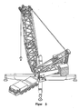
- FIG. 2 shows a crane according to the invention seen from behind.
- the superstructure 12 with boom 13 and counterweight 14 is rotatably connected via a rotary joint 15 with the center piece 6.
- the columns can be relatively long in this arrangement, whereby large moments occur in the supports. Since the left support 10 are passed through the bead 3, the height of the support 10 is limited by the height of the beads.
- the type of connection of the right support 11 removes this restriction.
- the underside of the support 11 is connected to the right-hand caterpillar. The top is struck against the center piece 6.
- the rear support 9 is attached only to the center piece. To reduce the moment in the support, like the front support 8, it can be attached to both the center piece and the caterpillars. Of course, it is also possible to attach the supports 8, 9 only to the caterpillars.
- FIG. 3 shows a further advantageous embodiment.
- a support 16 is designed such that a tilting edge is formed on the support. Based on FIGS. 4 and 5 the advantage is explained.
- FIG. 4 schematically four supports 17 are shown, which are arranged centrally to the center of rotation 2.
- the connecting line 18 between the ends of each two adjacent supports is referred to as tilting edge 18.
- a support 16 FIGS. 4 and 5
- FIG. 6 shows a typical conventional support.
- a hydraulic cylinder 21 is mounted, which is connected via a ball joint 22 with a support plate 23.
- the ball joint ensures that small uneven floors are compensated.
- a support according to the invention must at the end of a Have tilting edge.
- FIG. 7 One possible copy ( FIG. 7 ) consists of a support with a support cylinder 21 and two additional supports 24 which are mounted laterally in the front region of the support beam 20 on a cross member 25. In normal crane operation, the middle support cylinder 21 is used. To activate the additional support edge, the lateral supports 24 are extended. This can be done hydraulically or by spindle drive.
- FIG. 8 Another embodiment shows FIG. 8 , In the front area, two support cylinders 26, 27 are attached to a transverse bar 29. About ball joints they are connected to a support mat 28. To exclude Verzwteilungs theory, one of the cylinder 27 is rotatably mounted in the crossbar 29. When the additional tilting edge is activated, the hydraulic oil is locked in the cylinders. The arrangement is then rigid. In normal crane operation (standard support base), the cylinders are hydraulically balanced so that oil can flow freely from one cylinder to the other. Thus, the support mat is rotatable about a point between the cylinders. This possibility of being able to switch between normal operation and operation with extended tilting edge is not absolutely necessary. However, this ensures that the ground pressure distribution under the support mat 28 is uniform.
Landscapes
- Engineering & Computer Science (AREA)
- Mechanical Engineering (AREA)
- Jib Cranes (AREA)
- Vehicle Cleaning, Maintenance, Repair, Refitting, And Outriggers (AREA)
- Iron Core Of Rotating Electric Machines (AREA)
- Forklifts And Lifting Vehicles (AREA)
- Valve Device For Special Equipments (AREA)
- Vehicle Body Suspensions (AREA)
Claims (8)
- Grue, en particulier grue mobile, comprenant un châssis inférieur, un châssis supérieur (12) et une flèche (13) disposée sur celui-ci,
dans laquelle- le châssis supérieur est relié au châssis inférieur par l'intermédiaire d'un joint tournant (15),- sont prévus sur la grue plusieurs appuis (8-11, 16, 20) servant à élargir la base d'appui,- le châssis inférieur se compose d'une pièce médiane (6) et de mécanismes de roulement disposés de manière parallèle entre eux sur deux côtés de la pièce médiane,- sont prévus quatre appuis reliés au châssis inférieur, dont l'orientation est fixée de façon telle que deux appuis s'étendent le long de la direction de roulement (1) à l'intérieur de l'écartement du châssis inférieur et deux appuis sont orientés transversalement à cette direction à l'extérieur de l'écartement du châssis inférieur,caractérisée en ce que les mécanismes de roulement sont des trains de roulement à chenilles et en ce qu'au moins l'un des appuis latéraux (11) est raccordé, par sa face inférieure, au train de roulement à chenilles situé en regard, tandis que sa face supérieure est fixée sur la pièce médiane. - Grue selon l'une des revendications précédentes, caractérisée en ce qu'au moins l'un des appuis orientés transversalement est disposé directement sur le train de roulement à chenilles.
- Grue selon l'une des revendications précédentes, caractérisée en ce qu'au moins l'un des appuis orientés dans la direction longitudinale du châssis inférieur est fixé sur la pièce médiane.
- Grue selon l'une des revendications précédentes, caractérisée en ce qu'au moins l'un des appuis orientés dans la direction longitudinale du châssis inférieur est fixé aussi bien sur la pièce médiane que sur le train de roulement à chenilles.
- Grue selon l'une des revendications précédentes, caractérisée en ce qu'au moins l'un des appuis orientés dans la direction longitudinale du châssis inférieur est fixé sur le côté du train de roulement à chenilles orienté vers la pièce médiane.
- Grue selon l'une des revendications précédentes, caractérisée en ce que les appuis sont télescopiques.
- Grue selon l'une des revendications précédentes, caractérisée en ce que les appuis sont rabattables vers le haut ou latéralement.
- Grue selon l'une des revendications précédentes, caractérisée en ce que sont disposés, au niveau de la tête des appuis, des vérins d'appui extensibles établissant le contact avec la surface d'appui.
Priority Applications (1)
| Application Number | Priority Date | Filing Date | Title |
|---|---|---|---|
| EP09006475A EP2088115B1 (fr) | 2005-09-28 | 2006-08-22 | Grue |
Applications Claiming Priority (2)
| Application Number | Priority Date | Filing Date | Title |
|---|---|---|---|
| DE102005047745A DE102005047745A1 (de) | 2005-09-28 | 2005-09-28 | Kran, insbesondere mobiler Kran mit schmaler Spur und erweiterter Stützbasis |
| PCT/DE2006/001479 WO2007036188A2 (fr) | 2005-09-28 | 2006-08-22 | Grue, notamment grue mobile a ecartement etroit et base d'appui elargie |
Related Child Applications (2)
| Application Number | Title | Priority Date | Filing Date |
|---|---|---|---|
| EP09006475A Division-Into EP2088115B1 (fr) | 2005-09-28 | 2006-08-22 | Grue |
| EP09006475A Division EP2088115B1 (fr) | 2005-09-28 | 2006-08-22 | Grue |
Publications (2)
| Publication Number | Publication Date |
|---|---|
| EP1928778A2 EP1928778A2 (fr) | 2008-06-11 |
| EP1928778B1 true EP1928778B1 (fr) | 2010-02-10 |
Family
ID=37395775
Family Applications (2)
| Application Number | Title | Priority Date | Filing Date |
|---|---|---|---|
| EP06775898A Active EP1928778B1 (fr) | 2005-09-28 | 2006-08-22 | Grue, notamment grue mobile a ecartement etroit et base d'appui elargie |
| EP09006475A Active EP2088115B1 (fr) | 2005-09-28 | 2006-08-22 | Grue |
Family Applications After (1)
| Application Number | Title | Priority Date | Filing Date |
|---|---|---|---|
| EP09006475A Active EP2088115B1 (fr) | 2005-09-28 | 2006-08-22 | Grue |
Country Status (9)
| Country | Link |
|---|---|
| US (2) | US8499945B2 (fr) |
| EP (2) | EP1928778B1 (fr) |
| JP (1) | JP5405112B2 (fr) |
| CN (1) | CN101277894B (fr) |
| AT (2) | ATE487675T1 (fr) |
| CA (1) | CA2623713A1 (fr) |
| DE (4) | DE102005047745A1 (fr) |
| ES (2) | ES2339155T3 (fr) |
| WO (1) | WO2007036188A2 (fr) |
Families Citing this family (12)
| Publication number | Priority date | Publication date | Assignee | Title |
|---|---|---|---|---|
| US9284168B2 (en) * | 2009-10-01 | 2016-03-15 | Mw Industries, Inc. | Guyless service rig with side-mounted, pivotally deployable rear outriggers |
| DE102011102110B4 (de) | 2011-05-20 | 2023-05-17 | Liebherr-Werk Ehingen Gmbh | Unterwagen für Raupenkran, Raupenkran und Verfahren zum Auf- und Abbau eines Raupenkrans |
| DE102012001930A1 (de) | 2012-02-02 | 2013-08-08 | LTK GmbH | Vorrichtung zur kontinuierlichen Bestimmung der Standsicherheit und Verfahren zur Überwachung der Standsicherheit |
| US9238945B2 (en) | 2013-02-15 | 2016-01-19 | Black Hawk Energy Services, Inc. | Base beam and self-propelled derrick rig assembly |
| US20140231609A1 (en) * | 2013-02-15 | 2014-08-21 | Black Hawk Energy Services | Base beam for supporting a self-propelled derrick rig |
| US9212524B2 (en) | 2013-02-15 | 2015-12-15 | Black Hawk Energy Services, Inc. | Methods of supporting a self-propelled derrick rig |
| DE202016004687U1 (de) * | 2016-07-29 | 2017-11-02 | Liebherr-Werk Nenzing Gmbh | Mobile Arbeitsmaschine |
| DE102016011189A1 (de) * | 2016-09-15 | 2018-03-15 | Liebherr-Werk Ehingen Gmbh | Vorrichtung zum Stabilisieren eines Krans |
| CN107572433B (zh) * | 2017-10-11 | 2019-01-08 | 徐工集团工程机械有限公司 | 一种随车起重机防倾翻系统及方法 |
| DE102018113032A1 (de) * | 2018-05-30 | 2019-12-05 | David Mann | Stabilisierungseinrichtung und Verfahren zum Erhöhen der Standsicherheit mobiler Baumaschinen |
| CN111847285B (zh) * | 2020-08-13 | 2023-06-02 | 合肥工业大学 | 一种适用于柔索并联起重机器人的稳定调节机构及调节方法 |
| CN114408776B (zh) * | 2022-01-24 | 2023-03-10 | 浙江三一装备有限公司 | 起重机及其起臂方法 |
Family Cites Families (38)
| Publication number | Priority date | Publication date | Assignee | Title |
|---|---|---|---|---|
| DE129892C (fr) | ||||
| US527741A (en) * | 1894-10-16 | Means for supporting dredge or other structures | ||
| US2131479A (en) * | 1936-07-11 | 1938-09-27 | Clyde Iron Works | Loading hoist |
| US2139960A (en) * | 1937-08-11 | 1938-12-13 | Roy D Kauffman | Crane |
| US2910189A (en) * | 1956-08-02 | 1959-10-27 | Maschf Augsburg Nuernberg Ag | Rotary automobile crane |
| US2914194A (en) * | 1957-08-21 | 1959-11-24 | American Hoist & Derrick Co | Outrigger construction for carrier mounted cranes |
| US3021016A (en) * | 1959-12-15 | 1962-02-13 | Thew Shovel Co | Outriggers for crawler cranes, shovels, hoes and the like |
| US3878944A (en) * | 1973-08-30 | 1975-04-22 | Dantel E Beduhn | Crane support structure |
| DE2364296C3 (de) * | 1973-12-22 | 1980-01-24 | Fritz 5802 Wetter Metz | Abstützvorrichtung für Krane, Hebebühnen o.dgl |
| DE2517203A1 (de) * | 1975-04-18 | 1976-10-21 | Liebherr Werk Ehingen | Autokran |
| DD129892A1 (de) * | 1977-02-24 | 1978-02-15 | Rudolf Schulze | Abstuetzvorrichtung fuer kraftfahrzeuge,insbesondere eisenbahnkrane |
| GB1554735A (en) * | 1977-10-06 | 1979-10-31 | 600 Group Ltd | Crane carriers |
| US4196816A (en) * | 1977-11-01 | 1980-04-08 | Fmc Corporation | Heavy duty crane |
| US4273244A (en) * | 1979-01-29 | 1981-06-16 | Fmc Corporation | Crane upperstructure self-transferring system |
| US4394911A (en) * | 1980-04-08 | 1983-07-26 | Fmc Corporation | Heavy duty crane |
| EP0048076A1 (fr) * | 1980-08-18 | 1982-03-24 | AMERICAN HOIST & DERRICK COMPANY | Structure de grue mobile |
| US4394912A (en) * | 1980-11-07 | 1983-07-26 | Harnischfeger Corporation | Mobile crane having telescoping outriggers and power operated screw means for same |
| US4394913A (en) * | 1980-11-07 | 1983-07-26 | Harnischfeger Corporation | Crane having power operated outriggers and lock means therefor |
| US4387814A (en) * | 1981-09-08 | 1983-06-14 | The Manitowoc Company, Inc. | Traveling attachment for ring supported lift crane |
| US4446976A (en) * | 1982-02-16 | 1984-05-08 | Fmc Corporation | Reversible outrigger crane support |
| DD212722B1 (de) * | 1982-12-24 | 1986-10-29 | Sommerfeld Hans Ulrich | Bodenabstuetzung, insbesondere fuer krane oder bagger |
| FR2541661B1 (fr) | 1983-02-24 | 1986-01-31 | Ppm Sa | Ensemble de stabilisation pour engin mobile |
| DE3310491A1 (de) * | 1983-03-23 | 1984-10-04 | O & K Orenstein & Koppel Ag, 1000 Berlin | Abstuetzvorrichtung an kettenfahrzeugen |
| JPS609896U (ja) * | 1983-06-29 | 1985-01-23 | 株式会社神戸製鋼所 | 移動式クレ−ンの五点支持式アウトリガ装置 |
| US4579234A (en) * | 1984-03-16 | 1986-04-01 | American Hoist & Derrick Company | Self-erecting mobile crane |
| JPS60170392U (ja) * | 1984-04-18 | 1985-11-12 | 株式会社小松製作所 | クレ−ンのアウトリガ装置 |
| CH667448A5 (de) * | 1985-02-15 | 1988-10-14 | Ernst Zimmermann | Unterwagen eines schwerlastfahrzeuges, insbesondere eines mehrachsigen mobilkranes. |
| JPH0768702B2 (ja) * | 1990-05-28 | 1995-07-26 | 日本車輌製造株式会社 | 大型杭打機の分解輸送方法 |
| JPH07228485A (ja) * | 1994-02-18 | 1995-08-29 | Hitachi Constr Mach Co Ltd | 建設機械における走行体の伸縮検出装置 |
| DE29613415U1 (de) * | 1996-08-02 | 1996-09-19 | Compact Truck Ag | Kranfahrzeug |
| CA2266791C (fr) * | 1998-03-27 | 2005-02-01 | Manitowoc Crane Group, Inc. | Grue sur quatre chenilles |
| DE10020270B4 (de) * | 1999-08-04 | 2020-03-26 | Liebherr-Werk Ehingen Gmbh | Raupenkran |
| JP4763119B2 (ja) * | 1999-08-04 | 2011-08-31 | リープヘル−ヴェルク エーインゲン ゲーエムベーハー | クローラー搭載式クレーン |
| DE10023077C2 (de) | 2000-05-05 | 2002-07-11 | Mannesmann Ag | Abstützung für ein gleisgebundenes Kranfahrzeug, insbesondere für ein Zweiwegefahrzeug |
| DE10143716B4 (de) * | 2001-08-30 | 2004-04-15 | Terex-Demag Gmbh & Co. Kg | Mobiles Arbeitsgerät mit Stützträgern und Verfahren zum Betrieb dieses Arbeitsgeräts |
| US6848522B2 (en) * | 2002-04-19 | 2005-02-01 | Link-Belt Construction Equipment Co. L.P. , Lllp | Systems for connecting a ground-engaging motive device to a vehicle and related methods |
| DE20305683U1 (de) * | 2003-04-08 | 2004-08-19 | Liebherr-Werk Ehingen Gmbh | Fahrbarer Kran |
| US7328810B1 (en) * | 2003-12-22 | 2008-02-12 | Lester Kent Rhodes | Crane supporting apparatus |
-
2005
- 2005-09-28 DE DE102005047745A patent/DE102005047745A1/de not_active Withdrawn
-
2006
- 2006-08-22 DE DE202006020705U patent/DE202006020705U1/de not_active Expired - Lifetime
- 2006-08-22 EP EP06775898A patent/EP1928778B1/fr active Active
- 2006-08-22 CN CN2006800357652A patent/CN101277894B/zh not_active Expired - Fee Related
- 2006-08-22 JP JP2008532578A patent/JP5405112B2/ja active Active
- 2006-08-22 ES ES06775898T patent/ES2339155T3/es active Active
- 2006-08-22 AT AT09006475T patent/ATE487675T1/de active
- 2006-08-22 WO PCT/DE2006/001479 patent/WO2007036188A2/fr active Application Filing
- 2006-08-22 ES ES09006475T patent/ES2352640T3/es active Active
- 2006-08-22 EP EP09006475A patent/EP2088115B1/fr active Active
- 2006-08-22 US US11/992,718 patent/US8499945B2/en active Active
- 2006-08-22 DE DE502006008304T patent/DE502006008304D1/de active Active
- 2006-08-22 CA CA002623713A patent/CA2623713A1/fr not_active Abandoned
- 2006-08-22 AT AT06775898T patent/ATE457294T1/de active
- 2006-08-22 DE DE502006006122T patent/DE502006006122D1/de active Active
-
2010
- 2010-08-30 US US12/871,480 patent/US8225947B2/en active Active
Also Published As
| Publication number | Publication date |
|---|---|
| WO2007036188A2 (fr) | 2007-04-05 |
| US20100320166A1 (en) | 2010-12-23 |
| US8225947B2 (en) | 2012-07-24 |
| EP2088115A2 (fr) | 2009-08-12 |
| CN101277894A (zh) | 2008-10-01 |
| ATE457294T1 (de) | 2010-02-15 |
| EP2088115A3 (fr) | 2009-08-19 |
| ES2352640T3 (es) | 2011-02-22 |
| EP2088115B1 (fr) | 2010-11-10 |
| JP2009509888A (ja) | 2009-03-12 |
| CN101277894B (zh) | 2011-12-28 |
| DE202006020705U1 (de) | 2009-08-13 |
| DE102005047745A1 (de) | 2007-03-29 |
| ES2339155T3 (es) | 2010-05-17 |
| US8499945B2 (en) | 2013-08-06 |
| JP5405112B2 (ja) | 2014-02-05 |
| CA2623713A1 (fr) | 2007-04-05 |
| DE502006006122D1 (de) | 2010-03-25 |
| EP1928778A2 (fr) | 2008-06-11 |
| DE502006008304D1 (de) | 2010-12-23 |
| WO2007036188A3 (fr) | 2007-05-18 |
| ATE487675T1 (de) | 2010-11-15 |
| US20090107946A1 (en) | 2009-04-30 |
Similar Documents
| Publication | Publication Date | Title |
|---|---|---|
| EP1928778B1 (fr) | Grue, notamment grue mobile a ecartement etroit et base d'appui elargie | |
| EP1851159B1 (fr) | Bras d'appui destine a des machines de travail roulantes | |
| EP0538721B1 (fr) | Châssis pour véhicules chenillés | |
| EP2240360B1 (fr) | Engin de travail mobile | |
| EP1760031B1 (fr) | Châssis inférieur de grue optimisé pour transport | |
| DE1944214B2 (de) | Chienenlos verfahrbarer drehkranunterwagen | |
| DE102009016033A1 (de) | Gittermastkran und Gittermastausleger | |
| CH686365A5 (de) | Mobilkran. | |
| DE2029095A1 (de) | Ausleger | |
| DE2658250A1 (de) | Fahrbarer und hebbarer arbeitskorb | |
| EP2238071A1 (fr) | Engin de travail mobile | |
| DE202021106818U1 (de) | Mobilkran mit einer Gegengewichtsvorrichtung | |
| DE102011102110B4 (de) | Unterwagen für Raupenkran, Raupenkran und Verfahren zum Auf- und Abbau eines Raupenkrans | |
| EP3564182B1 (fr) | Pompe à béton automatique | |
| DE102013205888A1 (de) | Fahrbare Arbeitsmaschine, insbesondere Autobetonpumpe und Herstellungsverfahren | |
| AT523305A2 (de) | Fahrzeugkran | |
| DE102014012661B4 (de) | Verfahren zum Betrieb eines Krans und Kran | |
| DE102008006119B3 (de) | Mobilkran und Verfahren zur Montage | |
| EP1332896A1 (fr) | Véhicule amphibie de franchissement, formant un pont | |
| DE10143716B4 (de) | Mobiles Arbeitsgerät mit Stützträgern und Verfahren zum Betrieb dieses Arbeitsgeräts | |
| WO2006045609A1 (fr) | Grue mobile | |
| DE202006002023U1 (de) | Raupenkran | |
| EP3279044B1 (fr) | Machine de travail mobile | |
| EP1541520B1 (fr) | Grue mobile | |
| EP0947385A2 (fr) | Pompe à béton mobile |
Legal Events
| Date | Code | Title | Description |
|---|---|---|---|
| PUAI | Public reference made under article 153(3) epc to a published international application that has entered the european phase |
Free format text: ORIGINAL CODE: 0009012 |
|
| 17P | Request for examination filed |
Effective date: 20080229 |
|
| AK | Designated contracting states |
Kind code of ref document: A2 Designated state(s): AT BE BG CH CY CZ DE DK EE ES FI FR GB GR HU IE IS IT LI LT LU LV MC NL PL PT RO SE SI SK TR |
|
| 17Q | First examination report despatched |
Effective date: 20080916 |
|
| RAP1 | Party data changed (applicant data changed or rights of an application transferred) |
Owner name: TEREX DEMAG GMBH |
|
| GRAP | Despatch of communication of intention to grant a patent |
Free format text: ORIGINAL CODE: EPIDOSNIGR1 |
|
| DAX | Request for extension of the european patent (deleted) | ||
| GRAS | Grant fee paid |
Free format text: ORIGINAL CODE: EPIDOSNIGR3 |
|
| GRAA | (expected) grant |
Free format text: ORIGINAL CODE: 0009210 |
|
| AK | Designated contracting states |
Kind code of ref document: B1 Designated state(s): AT BE BG CH CY CZ DE DK EE ES FI FR GB GR HU IE IS IT LI LT LU LV MC NL PL PT RO SE SI SK TR |
|
| REG | Reference to a national code |
Ref country code: GB Ref legal event code: FG4D Free format text: NOT ENGLISH |
|
| REG | Reference to a national code |
Ref country code: CH Ref legal event code: EP |
|
| REG | Reference to a national code |
Ref country code: IE Ref legal event code: FG4D |
|
| REF | Corresponds to: |
Ref document number: 502006006122 Country of ref document: DE Date of ref document: 20100325 Kind code of ref document: P |
|
| REG | Reference to a national code |
Ref country code: SE Ref legal event code: TRGR |
|
| REG | Reference to a national code |
Ref country code: ES Ref legal event code: FG2A Ref document number: 2339155 Country of ref document: ES Kind code of ref document: T3 |
|
| REG | Reference to a national code |
Ref country code: NL Ref legal event code: VDEP Effective date: 20100210 |
|
| LTIE | Lt: invalidation of european patent or patent extension |
Effective date: 20100210 |
|
| PG25 | Lapsed in a contracting state [announced via postgrant information from national office to epo] |
Ref country code: LT Free format text: LAPSE BECAUSE OF FAILURE TO SUBMIT A TRANSLATION OF THE DESCRIPTION OR TO PAY THE FEE WITHIN THE PRESCRIBED TIME-LIMIT Effective date: 20100210 Ref country code: PT Free format text: LAPSE BECAUSE OF FAILURE TO SUBMIT A TRANSLATION OF THE DESCRIPTION OR TO PAY THE FEE WITHIN THE PRESCRIBED TIME-LIMIT Effective date: 20100611 Ref country code: IS Free format text: LAPSE BECAUSE OF FAILURE TO SUBMIT A TRANSLATION OF THE DESCRIPTION OR TO PAY THE FEE WITHIN THE PRESCRIBED TIME-LIMIT Effective date: 20100610 |
|
| PG25 | Lapsed in a contracting state [announced via postgrant information from national office to epo] |
Ref country code: SI Free format text: LAPSE BECAUSE OF FAILURE TO SUBMIT A TRANSLATION OF THE DESCRIPTION OR TO PAY THE FEE WITHIN THE PRESCRIBED TIME-LIMIT Effective date: 20100210 Ref country code: FI Free format text: LAPSE BECAUSE OF FAILURE TO SUBMIT A TRANSLATION OF THE DESCRIPTION OR TO PAY THE FEE WITHIN THE PRESCRIBED TIME-LIMIT Effective date: 20100210 Ref country code: LV Free format text: LAPSE BECAUSE OF FAILURE TO SUBMIT A TRANSLATION OF THE DESCRIPTION OR TO PAY THE FEE WITHIN THE PRESCRIBED TIME-LIMIT Effective date: 20100210 Ref country code: PL Free format text: LAPSE BECAUSE OF FAILURE TO SUBMIT A TRANSLATION OF THE DESCRIPTION OR TO PAY THE FEE WITHIN THE PRESCRIBED TIME-LIMIT Effective date: 20100210 |
|
| REG | Reference to a national code |
Ref country code: IE Ref legal event code: FD4D |
|
| PG25 | Lapsed in a contracting state [announced via postgrant information from national office to epo] |
Ref country code: RO Free format text: LAPSE BECAUSE OF FAILURE TO SUBMIT A TRANSLATION OF THE DESCRIPTION OR TO PAY THE FEE WITHIN THE PRESCRIBED TIME-LIMIT Effective date: 20100210 Ref country code: NL Free format text: LAPSE BECAUSE OF FAILURE TO SUBMIT A TRANSLATION OF THE DESCRIPTION OR TO PAY THE FEE WITHIN THE PRESCRIBED TIME-LIMIT Effective date: 20100210 Ref country code: IE Free format text: LAPSE BECAUSE OF FAILURE TO SUBMIT A TRANSLATION OF THE DESCRIPTION OR TO PAY THE FEE WITHIN THE PRESCRIBED TIME-LIMIT Effective date: 20100210 Ref country code: GR Free format text: LAPSE BECAUSE OF FAILURE TO SUBMIT A TRANSLATION OF THE DESCRIPTION OR TO PAY THE FEE WITHIN THE PRESCRIBED TIME-LIMIT Effective date: 20100511 Ref country code: EE Free format text: LAPSE BECAUSE OF FAILURE TO SUBMIT A TRANSLATION OF THE DESCRIPTION OR TO PAY THE FEE WITHIN THE PRESCRIBED TIME-LIMIT Effective date: 20100210 Ref country code: CY Free format text: LAPSE BECAUSE OF FAILURE TO SUBMIT A TRANSLATION OF THE DESCRIPTION OR TO PAY THE FEE WITHIN THE PRESCRIBED TIME-LIMIT Effective date: 20100210 |
|
| PG25 | Lapsed in a contracting state [announced via postgrant information from national office to epo] |
Ref country code: BG Free format text: LAPSE BECAUSE OF FAILURE TO SUBMIT A TRANSLATION OF THE DESCRIPTION OR TO PAY THE FEE WITHIN THE PRESCRIBED TIME-LIMIT Effective date: 20100510 Ref country code: SK Free format text: LAPSE BECAUSE OF FAILURE TO SUBMIT A TRANSLATION OF THE DESCRIPTION OR TO PAY THE FEE WITHIN THE PRESCRIBED TIME-LIMIT Effective date: 20100210 Ref country code: CZ Free format text: LAPSE BECAUSE OF FAILURE TO SUBMIT A TRANSLATION OF THE DESCRIPTION OR TO PAY THE FEE WITHIN THE PRESCRIBED TIME-LIMIT Effective date: 20100210 |
|
| PLBE | No opposition filed within time limit |
Free format text: ORIGINAL CODE: 0009261 |
|
| STAA | Information on the status of an ep patent application or granted ep patent |
Free format text: STATUS: NO OPPOSITION FILED WITHIN TIME LIMIT |
|
| 26N | No opposition filed |
Effective date: 20101111 |
|
| PG25 | Lapsed in a contracting state [announced via postgrant information from national office to epo] |
Ref country code: DK Free format text: LAPSE BECAUSE OF FAILURE TO SUBMIT A TRANSLATION OF THE DESCRIPTION OR TO PAY THE FEE WITHIN THE PRESCRIBED TIME-LIMIT Effective date: 20100210 |
|
| BERE | Be: lapsed |
Owner name: TEREX DEMAG G.M.B.H. Effective date: 20100831 |
|
| PG25 | Lapsed in a contracting state [announced via postgrant information from national office to epo] |
Ref country code: IT Free format text: LAPSE BECAUSE OF FAILURE TO SUBMIT A TRANSLATION OF THE DESCRIPTION OR TO PAY THE FEE WITHIN THE PRESCRIBED TIME-LIMIT Effective date: 20100210 Ref country code: MC Free format text: LAPSE BECAUSE OF NON-PAYMENT OF DUE FEES Effective date: 20100831 |
|
| REG | Reference to a national code |
Ref country code: CH Ref legal event code: PL |
|
| PG25 | Lapsed in a contracting state [announced via postgrant information from national office to epo] |
Ref country code: LI Free format text: LAPSE BECAUSE OF NON-PAYMENT OF DUE FEES Effective date: 20100831 Ref country code: CH Free format text: LAPSE BECAUSE OF NON-PAYMENT OF DUE FEES Effective date: 20100831 |
|
| REG | Reference to a national code |
Ref country code: FR Ref legal event code: ST Effective date: 20110502 |
|
| PG25 | Lapsed in a contracting state [announced via postgrant information from national office to epo] |
Ref country code: FR Free format text: LAPSE BECAUSE OF NON-PAYMENT OF DUE FEES Effective date: 20100831 Ref country code: BE Free format text: LAPSE BECAUSE OF NON-PAYMENT OF DUE FEES Effective date: 20100831 |
|
| PG25 | Lapsed in a contracting state [announced via postgrant information from national office to epo] |
Ref country code: LU Free format text: LAPSE BECAUSE OF NON-PAYMENT OF DUE FEES Effective date: 20100822 Ref country code: HU Free format text: LAPSE BECAUSE OF FAILURE TO SUBMIT A TRANSLATION OF THE DESCRIPTION OR TO PAY THE FEE WITHIN THE PRESCRIBED TIME-LIMIT Effective date: 20100811 |
|
| PG25 | Lapsed in a contracting state [announced via postgrant information from national office to epo] |
Ref country code: TR Free format text: LAPSE BECAUSE OF FAILURE TO SUBMIT A TRANSLATION OF THE DESCRIPTION OR TO PAY THE FEE WITHIN THE PRESCRIBED TIME-LIMIT Effective date: 20100210 |
|
| PGFP | Annual fee paid to national office [announced via postgrant information from national office to epo] |
Ref country code: AT Payment date: 20130813 Year of fee payment: 8 |
|
| PGFP | Annual fee paid to national office [announced via postgrant information from national office to epo] |
Ref country code: GB Payment date: 20130821 Year of fee payment: 8 |
|
| PGFP | Annual fee paid to national office [announced via postgrant information from national office to epo] |
Ref country code: ES Payment date: 20140826 Year of fee payment: 9 Ref country code: SE Payment date: 20140820 Year of fee payment: 9 |
|
| REG | Reference to a national code |
Ref country code: AT Ref legal event code: MM01 Ref document number: 457294 Country of ref document: AT Kind code of ref document: T Effective date: 20140822 |
|
| GBPC | Gb: european patent ceased through non-payment of renewal fee |
Effective date: 20140822 |
|
| PG25 | Lapsed in a contracting state [announced via postgrant information from national office to epo] |
Ref country code: AT Free format text: LAPSE BECAUSE OF NON-PAYMENT OF DUE FEES Effective date: 20140822 |
|
| PG25 | Lapsed in a contracting state [announced via postgrant information from national office to epo] |
Ref country code: GB Free format text: LAPSE BECAUSE OF NON-PAYMENT OF DUE FEES Effective date: 20140822 |
|
| REG | Reference to a national code |
Ref country code: SE Ref legal event code: EUG |
|
| PG25 | Lapsed in a contracting state [announced via postgrant information from national office to epo] |
Ref country code: SE Free format text: LAPSE BECAUSE OF NON-PAYMENT OF DUE FEES Effective date: 20150823 |
|
| REG | Reference to a national code |
Ref country code: DE Ref legal event code: R082 Ref document number: 502006006122 Country of ref document: DE Representative=s name: MOSER GOETZE & PARTNER PATENTANWAELTE MBB, DE Ref country code: DE Ref legal event code: R082 Ref document number: 502006006122 Country of ref document: DE Representative=s name: RAU, SCHNECK & HUEBNER PATENTANWAELTE RECHTSAN, DE Ref country code: DE Ref legal event code: R081 Ref document number: 502006006122 Country of ref document: DE Owner name: TEREX GLOBAL GMBH, CH Free format text: FORMER OWNER: TEREX-DEMAG GMBH, 66482 ZWEIBRUECKEN, DE |
|
| REG | Reference to a national code |
Ref country code: DE Ref legal event code: R082 Ref document number: 502006006122 Country of ref document: DE Representative=s name: MOSER GOETZE & PARTNER PATENTANWAELTE MBB, DE |
|
| PG25 | Lapsed in a contracting state [announced via postgrant information from national office to epo] |
Ref country code: ES Free format text: LAPSE BECAUSE OF NON-PAYMENT OF DUE FEES Effective date: 20150823 |
|
| REG | Reference to a national code |
Ref country code: ES Ref legal event code: FD2A Effective date: 20180703 |
|
| P01 | Opt-out of the competence of the unified patent court (upc) registered |
Effective date: 20230530 |
|
| PGFP | Annual fee paid to national office [announced via postgrant information from national office to epo] |
Ref country code: DE Payment date: 20230821 Year of fee payment: 18 |