EP1752257A2 - Outil à main avec réduction de vibration - Google Patents
Outil à main avec réduction de vibration Download PDFInfo
- Publication number
- EP1752257A2 EP1752257A2 EP06118250A EP06118250A EP1752257A2 EP 1752257 A2 EP1752257 A2 EP 1752257A2 EP 06118250 A EP06118250 A EP 06118250A EP 06118250 A EP06118250 A EP 06118250A EP 1752257 A2 EP1752257 A2 EP 1752257A2
- Authority
- EP
- European Patent Office
- Prior art keywords
- housing
- vibration
- hand tool
- vertical
- lateral
- Prior art date
- Legal status (The legal status is an assumption and is not a legal conclusion. Google has not performed a legal analysis and makes no representation as to the accuracy of the status listed.)
- Withdrawn
Links
Images


Classifications
-
- B—PERFORMING OPERATIONS; TRANSPORTING
- B25—HAND TOOLS; PORTABLE POWER-DRIVEN TOOLS; MANIPULATORS
- B25D—PERCUSSIVE TOOLS
- B25D17/00—Details of, or accessories for, portable power-driven percussive tools
- B25D17/04—Handles; Handle mountings
- B25D17/043—Handles resiliently mounted relative to the hammer housing
Definitions
- the invention relates to a hand tool, which generates vibrations during operation, such as in particular an electric hammer drill, a chisel or impact drill, a motor-driven saw, in particular a jigsaw or saber saw, or a separating or grinding device, in particular an angle grinder.
- the hand tool has a tool spindle extending in a horizontal direction.
- the tool spindle is at least partially accommodated in a main housing, which defines a housing mean plane, which is spanned for example by an axis of the tool spindle and a center of gravity.
- a vertical direction perpendicular to this direction is directed along the housing center plane.
- a lateral direction of the hand tool device is perpendicular to the housing center plane.
- the hand tool device has a handle housing which is supported on the main housing with a lateral intermediate position of a lateral vibration-reducing element.
- Such hand tools are held with one hand on a main handle, which is formed on the handle housing.
- the vibrations occurring during operation on the main housing occur on the handle as a result of the vibration-reducing elements only with significantly reduced intensity, which allows a more comfortable operation of the hand tool over longer periods of time.
- From the DE 3121882 is a hand tool known, in which two U-shaped support elements are provided on the housing and the main handle.
- the support elements of the housing are connected transversely to a longitudinal axis of the power tool via two rubber blocks each with the support elements of the main handle.
- the support members can move relative to each other when a force is exerted in the direction of the longitudinal axis.
- the support members are shaped so that they come into contact with an excessive rotation of the main handle relative to the housing with each other.
- a disadvantage of this attachment of the main handle to the hand tool is that the rubber elements in their connecting direction between the support elements have a relatively large dimension or must be relatively soft to achieve as desired in the longitudinal direction sufficient vibration damping.
- this can lead to a poor penetration of the main handle on the housing and thus to poor leadership of the power tool in operation.
- sufficient vibration damping is achieved in the longitudinal direction with good leadership stability, so it is not possible on the rubber blocks at the same time in the two directions perpendicular to the longitudinal direction to achieve a comparatively good vibration damping while maintaining good leadership stability.
- the present invention has for its object to avoid the disadvantages mentioned in a hand tool and to ensure a stable leadership with sufficient vibration reduction.
- the object is achieved in that the handle housing is supported in addition to the lateral intermediate position of the lateral vibration reducing both under horizontal interposition of at least one horizontal vibration reduction element and under vertical intermediate layer of at least one vertical vibration reduction element on the main housing.
- the handle housing can be held in all three directions exclusively with the respective intermediate layer of a vibration-reducing element on the main housing.
- a separate vibration reduction can be set in each direction, in which a sufficiently stable mounting of the handle housing is maintained on the main housing without hard layer between the two housings. This makes it possible to minimize the overall vibration during operation of the handle housing and at the same time to ensure a stable guidance of the power tool.
- At least one pair of vibration-reducing elements which are spaced apart from each other in the respective direction is provided in the lateral direction, horizontal direction and vertical direction. This is supported by the Vibration reducing elements of each pair in the opposite direction between the handle housing and the main housing from.
- the vibration-reducing elements of the respectively at least one respective pair are biased against each other in two directions from horizontal direction, vertical direction and lateral direction.
- the vibration-reducing elements of the respective at least one respective pair are biased against each other. In this way, an optimal vibration damping of the overall vibration on the handle housing can be achieved, at the same time a stable mounting of the handle housing and thus an exact guidance of the power tool is made possible against all three directions.
- a triple-acting first damping body is provided, on which both the lateral vibration-reducing element and the horizontal vibration-reducing element and the vertical vibration-reducing element are formed.
- the number of elements required for the vibration damping can be further reduced and thus the assembly can be further simplified.
- the elastic element in a vertical housing opening of a housing made of handle housing and main housing is held circumferentially and has a parallel to the housing opening extending recess.
- an element of the other housing through which may be formed, for example, peg-shaped or by any other projecting from one of the housing engagement contour.
- This circumferential liner allows a particularly stable storage of the handle housing to the main body.
- the elastic element is supported in the vertical direction opposite to both housings.
- two vibration-reducing elements are provided on the elastic element in each of the three directions, which are supported oppositely between the two housings.
- a bias in all three directions can be generated on a single elastic element.
- the vibration-reducing elements are at least partially made of a foamed plastic.
- the vibration-reducing elements or the damping body can be produced inexpensively.
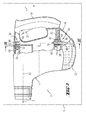
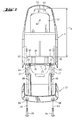
- Fig. 1 shows a hand tool 2 in the form of a hammer drill with a substantially three-piece housing.
- a main housing 4 while a motor 6 and a schematically illustrated gear 8 are housed. These drive a tool spindle 10 rotating and striking, which extends along a horizontal direction Z and on which a tool holder 14 is held against rotation.
- a handle 18 is formed over which the hand tool 2 is held with one hand, which simultaneously actuates a pusher 20 of a motor switch, not shown.
- the handle 18 extends substantially parallel to a vertical direction Y, which is perpendicular to the horizontal direction Z.
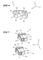
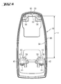
- the vertical direction Y and the horizontal direction Z lie in a housing center plane E, to which a lateral direction X is perpendicular, as can be seen from FIGS. 2 and 3.
- lateral direction X vertical direction Y and horizontal direction Z were chosen only by way of example according to the illustrated hand tool 2.
- the directions mentioned may also be directed differently.
- the names may differ depending on the orientation of the hand tool 2 in space from the corresponding spatial directions.
- a motor cover 22 is provided, which is formed separately from the main housing 4, and via which a housing opening 24 of the main housing 4 in the region of the motor 6 can be closed.
- This motor cover 22 can be fixed to the main housing 4 via screws 26 and extensions 27.
- the handle housing 16 can be connected to the main housing 4 or to the motor cover 22 by means of a connecting arrangement designated overall by 28.
- a first connection 50 has on the main housing side a convex engagement element 52 which protrudes on a gear housing 54 and can be engaged behind the interposition of a first elastic element 56 made of foamed plastic by a handle housing side rear grip element 58.
- the rear grip element 58 has a substantially concave receptacle 60, which is formed on the grip housing 16 and into which the first elastic element 56 can be inserted. This in turn forms a receiving space 62 which is open to one side and in which the convex engagement element 52 can be received, as can be seen in particular from FIG.
- the first elastic element 56 is shown isolated in Fig. 4 in perspective. As indicated by dot-dash lines herein, the receiving space 62 is bounded in the lateral direction X by two portions of the first elastic member 56, each of which functions as a lateral vibration reducing member 56a. In the vertical direction Y, a portion is provided on the first elastic member 56, which as a vertical Vibration reduction element 56b acts. In the horizontal direction Z, a total of four regions are further formed on the first elastic element 56, each of which functions as a horizontal vibration-reducing element 56c.
- the receiving space 62 has in the lateral direction X between the two lateral vibration-reducing elements 56a and in the horizontal direction Z between each two of the horizontal vibration-reducing elements 56c a slightly smaller extent than the respective extent of the convex engaging element 52 in each corresponding direction.
- the connection arrangement 28 furthermore has four main housing-side locking receptacles 30 in the form of recesses which are provided on four housing webs 36 projecting from a rear side 34 of the main housing 4.
- eyelet element 38 can be positioned between each two of the housing webs 36 between each two of the housing webs 36 .
- These eyelet elements 38 each have a handle-side locking receptacle 42 in the form of a continuous recess for receiving a second elastic element 40 made of foamed plastic.
- the second elastic elements 40 each have a passage recess 44. These passage recesses 44 can be brought into common alignment with the respectively adjacent main housing-side locking receptacles 30.
- connection arrangement 28 provides two peg-shaped latches 46, which protrude from the engine cover 22.
- the locking receptacles 30, 42 serve the second elastic elements 40 and the bars 46, as can be seen in particular from FIGS. 2 and 3, for producing a second connection 48 of the connection arrangement 28. This is perpendicular to the working axis 12 of the first connection 50 spaced apart.
- the two second elastic elements 40 are shown isolated in perspective. As indicated by dot-dashed lines herein, the respective through-hole 44 is bounded in the lateral direction X by two respective regions of the second elastic elements 40, each of which functions as a lateral vibration-reducing element 40a. Furthermore, in the horizontal direction Z, two regions each are formed on the two second elastic elements 40, each of which functions as a horizontal vibration-reducing element 40c.
- a collar-shaped vertical vibration-reducing element 40b is further formed, which projects transversely to the vertical direction Y beyond the remaining second elastic element 40.
- the vertical vibration-reducing elements 40 each form on their two sides, relative to the vertical direction Y, an upper contact surface FO and lower contact surface FU extending transversely to the vertical direction Y.
- the first elastic element 56 is inserted into the receptacle 60 on the rear grip element 58, as shown in FIG. 6, on the handle housing side. Further, the second elastic members 40 are inserted into the handle-side locking receptacles 42 which are bolted to the handle housing 16.
- the handle housing 16 is first brought into engagement with the convex engagement element 52 via the rear grip element 58 and the elastic element 56 inserted therein, as indicated in FIG. 1 by the mounting direction M1. Because of the above-described smaller dimensions of the receiving space 62 relative to the engaging element 52, the lateral vibration-reducing elements 56a and the horizontal vibration-reducing elements 56c in the receptacle 60 are biased in pairs against each other. The engagement element 52 is thus clamped on the handle housing 16 under lateral and horizontal interposition of the lateral vibration-reducing elements 56a and the horizontal vibration-reducing elements 56c.
- the remote from the working axis 12 lower end of the handle housing 16 is pivoted along the mounting direction M2 to the first connection 50 to the main housing 4.
- the distance a between the vertical vibration-reducing element 56b of the first elastic element 56 in the unloaded state and the two upper contact surfaces FO of the second elastic elements 40 in the unloaded state shown in FIG. 6 is slightly less than the distance b, according to FIG. 7, between a Top edge 63 of the engaging member 52 and lower sides 65 of the respectively closer to the engaging member 52 positioned housing webs 36, with which the two upper contact surfaces FO come into contact during assembly.
- the first elastic member 56 must be acted upon with a certain voltage in the vertical direction Y in order to pivot the ⁇ senimplantation 38 with the second elastic elements 40 held therein between the respective two housing webs 36 can.
- an elastic seal 66 is provided to seal the interior of the housing against the outside, as can be seen from Fig. 1.
- the motor cover 22 is then placed in the mounting direction M3 on the housing opening 24, as shown in particular in Fig. 5.
- the latch 46 are pushed through the handle-side locking receptacles 42 and the second elastic members 40, whereby the handle-side locking receptacles 42 with the main housing-side locking receptacles 30 by means of the bolt 46 with the interposition of the respective second elastic member 40 are positively connected to each other.
- the two passage recesses 44 have in the lateral direction X between the two lateral vibration-reducing elements 40a and in the horizontal direction Z between the two horizontal vibration-reducing elements 40c a slightly smaller extent than the respective extent of the latch 46 in each corresponding direction. Because of these smaller dimensions of the passage recesses 44 relative to the bolts 46, the lateral vibration-reducing elements 40a and the horizontal vibration-reducing elements 40c in the handle-side locking receptacles 42 are biased in pairs against each other. The bars 46 are thus clamped on the handle housing 16 under lateral and horizontal intermediate position of the lateral vibration-reducing elements 40a and the horizontal vibration-reducing elements 40c.
- the handle housing 16 is thus in all three directions X, Y, Z exclusively under respective intermediate layer of mutually prestressed against each other vibration reduction elements 40a, 40b, 40c, 56a, 56b, 56c, that is without hard layer on Main housing 4 held.
- the vibration reducing elements 40a, 40b, 40c, 56a, 56b, 56c are made of foamed plastic, in operation in all three directions X, Y, Z the vibration transmissions from the main body 4 to the handle housing 16 can be significantly dampened, thereby increasing the grip on the handle 18 occurring total vibration with stable leadership of the power tool 2 is significantly reduced.
- the rear grip element 58 is held perpendicular to the working axis 12 so close to the engagement element 52, that it can not be pivoted past this.
- a locking of the engagement on the first connection 50 takes place.
Landscapes
- Engineering & Computer Science (AREA)
- Mechanical Engineering (AREA)
- Percussive Tools And Related Accessories (AREA)
- Portable Power Tools In General (AREA)
- Sawing (AREA)
- Drilling And Boring (AREA)
Applications Claiming Priority (1)
| Application Number | Priority Date | Filing Date | Title |
|---|---|---|---|
| DE102005038091A DE102005038091A1 (de) | 2005-08-11 | 2005-08-11 | Handwerkzeuggerät mit Vibrationsminderung |
Publications (2)
| Publication Number | Publication Date |
|---|---|
| EP1752257A2 true EP1752257A2 (fr) | 2007-02-14 |
| EP1752257A3 EP1752257A3 (fr) | 2009-04-22 |
Family
ID=37440649
Family Applications (1)
| Application Number | Title | Priority Date | Filing Date |
|---|---|---|---|
| EP06118250A Withdrawn EP1752257A3 (fr) | 2005-08-11 | 2006-08-01 | Outil à main avec réduction de vibration |
Country Status (4)
| Country | Link |
|---|---|
| US (1) | US20070034397A1 (fr) |
| EP (1) | EP1752257A3 (fr) |
| JP (1) | JP2007044868A (fr) |
| DE (1) | DE102005038091A1 (fr) |
Cited By (2)
| Publication number | Priority date | Publication date | Assignee | Title |
|---|---|---|---|---|
| EP2468455A4 (fr) * | 2009-12-25 | 2014-02-26 | Makita Corp | Outil de frappe |
| EP2942158A1 (fr) * | 2014-05-09 | 2015-11-11 | HILTI Aktiengesellschaft | Machine-outil portative |
Families Citing this family (20)
| Publication number | Priority date | Publication date | Assignee | Title |
|---|---|---|---|---|
| WO2007048435A1 (fr) * | 2005-10-29 | 2007-05-03 | Aeg Electric Tools Gmbh | Outil portable a moteur |
| DE102006000253A1 (de) * | 2006-05-30 | 2007-12-06 | Hilti Ag | Schlagende Handwerkzeugmaschine mit axial beweglich gelagertem Schlagwerk |
| DE102006000287A1 (de) * | 2006-06-09 | 2007-12-13 | Hilti Ag | Handwerkzeuggerät mit Vibrationsminderungseinrichtung |
| DE102006029630A1 (de) * | 2006-06-28 | 2008-01-03 | Robert Bosch Gmbh | Handwerkzeugmaschine |
| DE102007000093A1 (de) * | 2007-02-15 | 2008-08-21 | Hilti Ag | Handwerkzeuggerät |
| DE102007028382A1 (de) * | 2007-06-20 | 2008-12-24 | Robert Bosch Gmbh | Handwerkzeugmaschinengehäuseeinheit |
| GB0801313D0 (en) * | 2008-01-24 | 2008-03-05 | Black & Decker Inc | Handle for power tool |
| DE102008006030A1 (de) * | 2008-01-25 | 2009-07-30 | Robert Bosch Gmbh | Handwerkzeugmaschine, insbesondere elektrisch betriebene Handwerkzeugmaschine |
| JP5361504B2 (ja) * | 2009-04-10 | 2013-12-04 | 株式会社マキタ | 打撃工具 |
| DE102009002589A1 (de) * | 2009-04-23 | 2010-10-28 | Hilti Aktiengesellschaft | Handwerkzeugmaschine |
| JP5726654B2 (ja) * | 2011-07-01 | 2015-06-03 | 株式会社マキタ | 打撃工具 |
| EP3636389A1 (fr) | 2012-02-03 | 2020-04-15 | Milwaukee Electric Tool Corporation | Marteau rotatif |
| US9849577B2 (en) | 2012-02-03 | 2017-12-26 | Milwaukee Electric Tool Corporation | Rotary hammer |
| US8966773B2 (en) | 2012-07-06 | 2015-03-03 | Techtronic Power Tools Technology Limited | Power tool including an anti-vibration handle |
| JP6278830B2 (ja) * | 2014-05-16 | 2018-02-14 | 株式会社マキタ | 打撃工具 |
| CN109019721B (zh) * | 2018-10-17 | 2024-02-02 | 杭州老板电器股份有限公司 | 增压装置及净水机 |
| CN216442260U (zh) | 2019-06-12 | 2022-05-06 | 米沃奇电动工具公司 | 电动工具 |
| JP7624319B2 (ja) * | 2021-02-04 | 2025-01-30 | 株式会社マキタ | 打撃工具 |
| JP7585085B2 (ja) * | 2021-02-22 | 2024-11-18 | 株式会社マキタ | 打撃工具 |
| US11759938B2 (en) | 2021-10-19 | 2023-09-19 | Makita Corporation | Impact tool |
Family Cites Families (25)
| Publication number | Priority date | Publication date | Assignee | Title |
|---|---|---|---|---|
| US3322211A (en) * | 1964-05-06 | 1967-05-30 | Novosib Elektrotekhnichesky I | Elastic handle for vibrating-impact mechanisms |
| US3481411A (en) * | 1968-02-19 | 1969-12-02 | Black & Decker Mfg Co | Sonic tool with means for reducing noise level |
| US3652074A (en) * | 1970-06-26 | 1972-03-28 | Mcculloch Corp | Mounting means for isolating vibrational energy in chain saw machines |
| GB1419826A (en) * | 1973-02-17 | 1975-12-31 | Dobson Park Ind | Excavating machines rock breaking machines and the like on a reproduction drum and removing it therefrom |
| JPS5834271B2 (ja) * | 1980-07-18 | 1983-07-26 | 日立工機株式会社 | 振動工具のハンドル防振装置 |
| JPS5946748B2 (ja) * | 1980-10-22 | 1984-11-14 | 一登 背戸 | 防振用ハンドル装置 |
| DE3122979A1 (de) * | 1981-06-10 | 1983-01-05 | Hilti AG, 9494 Schaan | Bohr- oder meisselhammer |
| DE3312195A1 (de) * | 1983-04-02 | 1984-10-11 | Wacker-Werke Gmbh & Co Kg, 8077 Reichertshofen | Handgefuehrter schlag- und bohrhammer |
| JPS6047838U (ja) * | 1983-09-09 | 1985-04-04 | 株式会社共立 | スロツトルクツシヨン |
| DE3410669A1 (de) * | 1984-03-23 | 1985-10-24 | Metabowerke GmbH & Co, 7440 Nürtingen | Daempfungselement und dessen einbau in ein motorisch angetriebenes handwerkzeug |
| JP2534318B2 (ja) * | 1988-04-30 | 1996-09-11 | 日立工機株式会社 | 動力工具の防振ハンドル |
| DE3839207A1 (de) * | 1988-11-19 | 1990-05-23 | Hilti Ag | Tragbares handgeraet mit schlagwerk |
| US5016355A (en) * | 1990-06-25 | 1991-05-21 | Textron Inc. | Vibration reducing chain saw handle |
| US5839517A (en) * | 1993-01-27 | 1998-11-24 | Lord Corporation | Vibration isolator for hand-held vibrating devices |
| JPH08126975A (ja) * | 1994-10-28 | 1996-05-21 | Hitachi Koki Co Ltd | 電気ハンマの防振ハンドル |
| JPH0825249A (ja) * | 1994-07-12 | 1996-01-30 | Makita Corp | 振動工具及び防振リング |
| US5697456A (en) * | 1995-04-10 | 1997-12-16 | Milwaukee Electric Tool Corp. | Power tool with vibration isolated handle |
| DE19530712B4 (de) * | 1995-08-21 | 2006-12-28 | Fa. Andreas Stihl | Antivibrationselement zur Anordnung zwischen einer Motoreinheit und einer Griffeinheit bei einem handgeführten Arbeitsgerät |
| DE19646622B4 (de) * | 1996-11-12 | 2004-07-01 | Wacker Construction Equipment Ag | An einem Handgriff führbares Arbeitsgerät |
| DE29700003U1 (de) * | 1997-01-02 | 1997-02-27 | Wacker-Werke Gmbh & Co Kg, 85084 Reichertshofen | Aufbruch- und/oder Bohrhammer |
| US6026910A (en) * | 1998-01-13 | 2000-02-22 | Chicago Pneumatic Tool Company | Power tool and vibration isolator therefor |
| FR2797208B1 (fr) * | 1999-08-03 | 2002-10-18 | Stihl Maschf Andreas | Element antivibrations pourvu d'une surete d'arrachement |
| JP2002039267A (ja) * | 2000-07-31 | 2002-02-06 | Kioritz Corp | 防振部材及び防振装置 |
| JP4157382B2 (ja) * | 2001-04-11 | 2008-10-01 | ローベルト ボツシユ ゲゼルシヤフト ミツト ベシユレンクテル ハフツング | 振動減衰式のハンドグリップを備えた手持ち工作機械 |
| DE10334906B4 (de) * | 2002-07-30 | 2018-11-15 | Andreas Stihl Ag & Co. Kg | Antivibrationselement |
-
2005
- 2005-08-11 DE DE102005038091A patent/DE102005038091A1/de not_active Withdrawn
-
2006
- 2006-08-01 EP EP06118250A patent/EP1752257A3/fr not_active Withdrawn
- 2006-08-09 JP JP2006216949A patent/JP2007044868A/ja not_active Withdrawn
- 2006-08-10 US US11/502,111 patent/US20070034397A1/en not_active Abandoned
Cited By (5)
| Publication number | Priority date | Publication date | Assignee | Title |
|---|---|---|---|---|
| EP2468455A4 (fr) * | 2009-12-25 | 2014-02-26 | Makita Corp | Outil de frappe |
| RU2563417C2 (ru) * | 2009-12-25 | 2015-09-20 | Макита Корпорейшн | Ударный инструмент |
| US9999967B2 (en) | 2009-12-25 | 2018-06-19 | Makita Corporation | Striking tool |
| EP2942158A1 (fr) * | 2014-05-09 | 2015-11-11 | HILTI Aktiengesellschaft | Machine-outil portative |
| WO2015169515A1 (fr) * | 2014-05-09 | 2015-11-12 | Hilti Aktiengesellschaft | Machine-outil à main |
Also Published As
| Publication number | Publication date |
|---|---|
| JP2007044868A (ja) | 2007-02-22 |
| US20070034397A1 (en) | 2007-02-15 |
| DE102005038091A1 (de) | 2007-02-15 |
| EP1752257A3 (fr) | 2009-04-22 |
Similar Documents
| Publication | Publication Date | Title |
|---|---|---|
| EP1752257A2 (fr) | Outil à main avec réduction de vibration | |
| EP1752260B1 (fr) | Outil à main avec une connection entre le boîtier principal et le boîtier de poignée | |
| EP1620233B1 (fr) | Machine-outil manuelle electrique comportant un bloc d'accumulateur | |
| DE3121882C2 (de) | Vibrationswerkzeug mit einem vibrationsfesten Befestigungsmechanismus für den Handgriff | |
| EP4025482B1 (fr) | Dispositif de fixation pour le montage amovible d'un accumulateur sur un cadre de bicyclette | |
| EP2841236B1 (fr) | Machine-outil portable dotée d'un boîtier externe | |
| EP2160272A1 (fr) | Unité de boîtier pour des machines-outils manuelles | |
| DE102007000093A1 (de) | Handwerkzeuggerät | |
| EP0267311A1 (fr) | Lame de scie pour une scie avec deux lames disposées côte à côte en parallèle et oscillantes en sens inverse | |
| DE19521423A1 (de) | Handwerkzeugmaschine mit batteriegespeistem Antriebsmotor und Batterie-Baueinheit für eine derartige Handwerkzeugmaschine sowie Handwerkzeugmaschine mit Batterie-Baueinheit | |
| DE102006029630A1 (de) | Handwerkzeugmaschine | |
| DE102007022115A1 (de) | Handgeführtes Arbeitsgerät | |
| DE102017101992A1 (de) | Kraftwerkzeug | |
| DE102005000205A1 (de) | Handgriff eines handgeführten Werkzeuggerätes | |
| DE112021004243T5 (de) | Elektrowerkzeug | |
| DE69936127T2 (de) | Sägeblattaufspannvorrichtung | |
| EP1674216B1 (fr) | Poignée latérale | |
| DE102014217992B4 (de) | Akkupack für eine Handwerkzeugmaschine | |
| EP1849561B1 (fr) | Outil manuel doté d'une poignée réglable | |
| DE10236135A1 (de) | Werkzeug | |
| EP2203947A1 (fr) | Bloc d'accumulateur et appareil électrique avec des moyens de codage tridimensionnels | |
| DE102006059348A1 (de) | Handwerkzeugmaschine mit schwingungsentkoppeltem Handgriff | |
| EP3865262A1 (fr) | Appareil de traitement guidé à la main pourvu de carter moteur | |
| EP3274132B1 (fr) | Machine-outil portative | |
| EP1674210B1 (fr) | Outil avec poignée principale mécaniquement découplée |
Legal Events
| Date | Code | Title | Description |
|---|---|---|---|
| PUAI | Public reference made under article 153(3) epc to a published international application that has entered the european phase |
Free format text: ORIGINAL CODE: 0009012 |
|
| AK | Designated contracting states |
Kind code of ref document: A2 Designated state(s): AT BE BG CH CY CZ DE DK EE ES FI FR GB GR HU IE IS IT LI LT LU LV MC NL PL PT RO SE SI SK TR |
|
| AX | Request for extension of the european patent |
Extension state: AL BA HR MK YU |
|
| PUAL | Search report despatched |
Free format text: ORIGINAL CODE: 0009013 |
|
| AK | Designated contracting states |
Kind code of ref document: A3 Designated state(s): AT BE BG CH CY CZ DE DK EE ES FI FR GB GR HU IE IS IT LI LT LU LV MC NL PL PT RO SE SI SK TR |
|
| AX | Request for extension of the european patent |
Extension state: AL BA HR MK RS |
|
| 17P | Request for examination filed |
Effective date: 20091022 |
|
| 17Q | First examination report despatched |
Effective date: 20091118 |
|
| AKX | Designation fees paid |
Designated state(s): CH DE FR GB LI SE |
|
| STAA | Information on the status of an ep patent application or granted ep patent |
Free format text: STATUS: THE APPLICATION IS DEEMED TO BE WITHDRAWN |
|
| 18D | Application deemed to be withdrawn |
Effective date: 20100529 |