EP1751433B1 - Support d'article - Google Patents
Support d'article Download PDFInfo
- Publication number
- EP1751433B1 EP1751433B1 EP05747631A EP05747631A EP1751433B1 EP 1751433 B1 EP1751433 B1 EP 1751433B1 EP 05747631 A EP05747631 A EP 05747631A EP 05747631 A EP05747631 A EP 05747631A EP 1751433 B1 EP1751433 B1 EP 1751433B1
- Authority
- EP
- European Patent Office
- Prior art keywords
- article support
- hook
- pillar
- engaging element
- base
- Prior art date
- Legal status (The legal status is an assumption and is not a legal conclusion. Google has not performed a legal analysis and makes no representation as to the accuracy of the status listed.)
- Not-in-force
Links
- 125000006850 spacer group Chemical group 0.000 claims description 13
- 239000005357 flat glass Substances 0.000 description 32
- 239000011521 glass Substances 0.000 description 22
- 239000000853 adhesive Substances 0.000 description 10
- 230000001070 adhesive effect Effects 0.000 description 10
- 230000002123 temporal effect Effects 0.000 description 10
- 238000010276 construction Methods 0.000 description 9
- 239000004820 Pressure-sensitive adhesive Substances 0.000 description 7
- 238000006073 displacement reaction Methods 0.000 description 7
- 239000012790 adhesive layer Substances 0.000 description 6
- 229920001187 thermosetting polymer Polymers 0.000 description 6
- 230000000630 rising effect Effects 0.000 description 5
- 230000000694 effects Effects 0.000 description 3
- 230000005484 gravity Effects 0.000 description 3
- WYTGDNHDOZPMIW-RCBQFDQVSA-N alstonine Natural products C1=CC2=C3C=CC=CC3=NC2=C2N1C[C@H]1[C@H](C)OC=C(C(=O)OC)[C@H]1C2 WYTGDNHDOZPMIW-RCBQFDQVSA-N 0.000 description 2
- 239000012141 concentrate Substances 0.000 description 2
- 238000004519 manufacturing process Methods 0.000 description 2
- 238000000034 method Methods 0.000 description 2
- -1 polybutylene terephthalate Polymers 0.000 description 2
- 238000003825 pressing Methods 0.000 description 2
- 239000004677 Nylon Substances 0.000 description 1
- 229930182556 Polyacetal Natural products 0.000 description 1
- 230000002401 inhibitory effect Effects 0.000 description 1
- 239000000463 material Substances 0.000 description 1
- 230000004048 modification Effects 0.000 description 1
- 238000012986 modification Methods 0.000 description 1
- 229920001778 nylon Polymers 0.000 description 1
- 229920001707 polybutylene terephthalate Polymers 0.000 description 1
- 229920006324 polyoxymethylene Polymers 0.000 description 1
- 239000011347 resin Substances 0.000 description 1
- 229920005989 resin Polymers 0.000 description 1
- 239000000565 sealant Substances 0.000 description 1
Images


Classifications
-
- F—MECHANICAL ENGINEERING; LIGHTING; HEATING; WEAPONS; BLASTING
- F16—ENGINEERING ELEMENTS AND UNITS; GENERAL MEASURES FOR PRODUCING AND MAINTAINING EFFECTIVE FUNCTIONING OF MACHINES OR INSTALLATIONS; THERMAL INSULATION IN GENERAL
- F16B—DEVICES FOR FASTENING OR SECURING CONSTRUCTIONAL ELEMENTS OR MACHINE PARTS TOGETHER, e.g. NAILS, BOLTS, CIRCLIPS, CLAMPS, CLIPS OR WEDGES; JOINTS OR JOINTING
- F16B5/00—Joining sheets or plates, e.g. panels, to one another or to strips or bars parallel to them
- F16B5/06—Joining sheets or plates, e.g. panels, to one another or to strips or bars parallel to them by means of clamps or clips
- F16B5/0607—Joining sheets or plates, e.g. panels, to one another or to strips or bars parallel to them by means of clamps or clips joining sheets or plates to each other
- F16B5/0621—Joining sheets or plates, e.g. panels, to one another or to strips or bars parallel to them by means of clamps or clips joining sheets or plates to each other in parallel relationship
- F16B5/065—Joining sheets or plates, e.g. panels, to one another or to strips or bars parallel to them by means of clamps or clips joining sheets or plates to each other in parallel relationship the plates being one on top of the other and distanced from each other, e.g. by using protrusions to keep contact and distance
-
- F—MECHANICAL ENGINEERING; LIGHTING; HEATING; WEAPONS; BLASTING
- F16—ENGINEERING ELEMENTS AND UNITS; GENERAL MEASURES FOR PRODUCING AND MAINTAINING EFFECTIVE FUNCTIONING OF MACHINES OR INSTALLATIONS; THERMAL INSULATION IN GENERAL
- F16B—DEVICES FOR FASTENING OR SECURING CONSTRUCTIONAL ELEMENTS OR MACHINE PARTS TOGETHER, e.g. NAILS, BOLTS, CIRCLIPS, CLAMPS, CLIPS OR WEDGES; JOINTS OR JOINTING
- F16B21/00—Means for preventing relative axial movement of a pin, spigot, shaft or the like and a member surrounding it; Stud-and-socket releasable fastenings
- F16B21/06—Releasable fastening devices with snap-action
- F16B21/08—Releasable fastening devices with snap-action in which the stud, pin, or spigot has a resilient part
- F16B21/088—Releasable fastening devices with snap-action in which the stud, pin, or spigot has a resilient part the stud, pin or spigot being integrally formed with the component to be fastened, e.g. forming part of the sheet, plate or strip
-
- F—MECHANICAL ENGINEERING; LIGHTING; HEATING; WEAPONS; BLASTING
- F16—ENGINEERING ELEMENTS AND UNITS; GENERAL MEASURES FOR PRODUCING AND MAINTAINING EFFECTIVE FUNCTIONING OF MACHINES OR INSTALLATIONS; THERMAL INSULATION IN GENERAL
- F16B—DEVICES FOR FASTENING OR SECURING CONSTRUCTIONAL ELEMENTS OR MACHINE PARTS TOGETHER, e.g. NAILS, BOLTS, CIRCLIPS, CLAMPS, CLIPS OR WEDGES; JOINTS OR JOINTING
- F16B5/00—Joining sheets or plates, e.g. panels, to one another or to strips or bars parallel to them
- F16B5/06—Joining sheets or plates, e.g. panels, to one another or to strips or bars parallel to them by means of clamps or clips
- F16B5/0607—Joining sheets or plates, e.g. panels, to one another or to strips or bars parallel to them by means of clamps or clips joining sheets or plates to each other
- F16B5/0621—Joining sheets or plates, e.g. panels, to one another or to strips or bars parallel to them by means of clamps or clips joining sheets or plates to each other in parallel relationship
- F16B5/0664—Joining sheets or plates, e.g. panels, to one another or to strips or bars parallel to them by means of clamps or clips joining sheets or plates to each other in parallel relationship at least one of the sheets or plates having integrally formed or integrally connected snap-in-features
-
- Y—GENERAL TAGGING OF NEW TECHNOLOGICAL DEVELOPMENTS; GENERAL TAGGING OF CROSS-SECTIONAL TECHNOLOGIES SPANNING OVER SEVERAL SECTIONS OF THE IPC; TECHNICAL SUBJECTS COVERED BY FORMER USPC CROSS-REFERENCE ART COLLECTIONS [XRACs] AND DIGESTS
- Y10—TECHNICAL SUBJECTS COVERED BY FORMER USPC
- Y10T—TECHNICAL SUBJECTS COVERED BY FORMER US CLASSIFICATION
- Y10T24/00—Buckles, buttons, clasps, etc.
- Y10T24/30—Trim molding fastener
- Y10T24/309—Plastic type
Definitions
- the present invention relates to an article support for supporting an article while the article support is fixedly attached to another object.
- an article support for supporting an article fastened to a base while a mount section provided on the base is attached to another object, wherein the mount section mainly bears any load on the object.
- Such article support can be used, for example, for temporal fixing while adhesive is being cured when a window glass for a car is bonded to a window frame of a car body.
- Japanese Unexamined Patent Publication (Kokai) No. 8-310233 discloses an article support used for temporal fixing of a window glass for a vehicle.
- This article support has: a base plate sticked on a window glass; a leg member standing on the base plate; and a nail section provided at a distal end of the leg member to be engaged with a vehicle body.
- a mounting hole is formed at the edge of an opening (a window frame) of the vehicle body and, then, the leg member of the article support, the base plate of which is sticked on the window glass via pressure sensitive adhesive double coated tape, is inserted into the mounting hole from the distal end.
- Japanese Unexamined Patent Publication (Kokai) No. 9-142141 discloses an article support used for temporal fixing of a window glass for a vehicle, comprising: a base plate sticked on a window glass; a pair of hooks standing on a back surface of the base plate; and a spacer disposed between the hooks on the back surface of the base plate in a rockable manner.
- a clip support section and notch sections on the both sides of the clip support section are formed in a window frame flange of a vehicle body.
- the spacer In the state in which the base plate is sticked on the window glass, the spacer is allowed to abut against the clip support section in the window frame of the vehicle and the window glass is pressed against the window frame of the vehicle while the spacer is being rocked with respect to the base plate so that the both hooks are engaged with the notch sections and the article support is fixedly fastened to the window frame of the vehicle.
- the spacer abuts against the clip supports section continuously, the weight of the window glass can be borne and, on the other hand, the base plate and, thus, the window glass is fixedly held at a position separated from the window frame of the vehicle by a predetermined distance by cooperation of the spacer and the hooks.
- an article support used for temporal fixing of a window glass of a vehicle is also disclosed by Japanese Unexamined Utility Model Publication (Kokai) No. 6-32132 , this article support cannot bear the weight of the window glass by itself
- an article support for temporal fixture of a window glass set forth in Japanese Unexamined Utility Model Publication (Kokai) No. 7-39517 adopts a hook-and-loop fastener structure as means for fastening to the window glass. In this configuration, as it is necessary to use two separate fastener components removably hooking on each other at one article supporting position, the operation for attaching the article support and parts control tend to become complicated.
- the article support set forth above in Japanese Unexamined Patent Publication (Kokai) No. 8-310233 adopts a construction in which the rising piece is formed in the neighborhood of the mounting hole in the vehicle body, into which the leg member is inserted, and the presser section at the base end of the leg member is allowed to abut against the rising piece to bear loads such as the weight of the window glass. Therefore, this article support lacks versatility because the object, to which the article support is attached, must be provided with an abutment region for the presser section apart from the engagement position for the nail section even when this article support is used in applications other than the temporal fixing of the window glass.
- leg member solely has both an engagement maintaining function of the nail portion and a load bearing function of the presser section
- loads concentrate on the leg member and stress concentration occurs on the pressure sensitive adhesive double coated tape sticking the article support on the article (the window glass) in the region corresponding to the leg member.
- the article support is likely to be offset with respect to the article.
- the article support set forth above in Japanese Unexamined Patent Publication (Kokai) No. 9-142141 adopts a construction in which the spacer provided on the back surface of the base plate is allowed to abut against the clip supporting section provided in the flange of the window frame of the vehicle body so that the article support is positioned with respect to the window frame of the vehicle body before the hooks are engaged with the window frame of the vehicle body. Therefore, this article support also lacks versatility because the object, to which the article support is attached, must be provided with an abutment region for the spacer apart from the engagement position for the hooks.
- this article support has a construction in which the loads concentrate on one spacer, again, while the article is supported on the object, it is likely that stress concentration occurs on the adhesive layer for sticking the article support on the article (the window glass) and that the article support is offset with respect to the article.
- the automobile manufacturing process including the operation for temporal fixing of the window glass described above becomes automated by robot.
- a technique for aligning the article support on the window glass with the mounting hole on the vehicle body with high accuracy by robot so as to insert the mount section of the article support into the mounting hole accurately when the article support of the type described above is used for temporal fixing of the window glass.
- the mount section may not be inserted into the mounting hole smoothly and the engagement maintaining elements (the nail section and the hooks) of the mount section may not be engaged with the edge of the mounting hole stably. It is desired that the mount section has adaptability to a certain error range so that the window glass can be temporarily fixed reliably without inhibiting automatic attachment of the window glass by robot also in such case.
- the present invention can provide an article support for supporting an article fastened to a base while a mount section provided on the base is attached to another object, where the invention can exhibit one or more of the following advantages: positional displacement with respect to the article is not likely to occur while the article support bears any load on the object, the mount section has adaptability to a certain error range, and a construction of the attachment position on the object can be simplified.
- the pillar of the first engaging element and the pillars of the second engaging elements can be spaced apart from, each other on the base.
- the pillar of the first engaging element can protrude higher than the pillars of the second engaging elements on the base.
- the pillar of the first engaging element can include a guide face that is able to contact the object during an attaching operation of the mount section to the object for guiding the first hook and the second hooks toward a position for engagement with the object.
- the pillar and the first hook of the first engaging element can be engaged with the object while the pillars of the second engaging elements are not engaged with the object.
- the mount section is attached to the object, the pillar of the first engaging element can bear a load on the object, and the first hook and the second hooks can be engaged with the object to fixedly hold the article support on the object.
- At least one of the first hook and the second hooks can be supported at its both ends between the base and the pillar. At least one of the first hook and the second hooks can include a spacer element for defining a predetermined minimum distance between the base and the object, when the mount section is attached to the object.
- the first hook of the first engaging element and the second hook of the second engaging element can be elastically engaged with the object independently of each other so as to fixedly hold the article support with respect to the object and, at the same time, the pillar of any of the first and second engaging elements disposed on the opposite side to the hooks can be engaged with the object so as to bear loads such as the weight of the object.
- the first hook or the second hook can also act to bear the loads such as the weight of the object in an auxiliary manner. Therefore, concentration of loads on one engaging element and stress concentration on an adhesive layer, when the article support is fastened to the article via the adhesive layer, can be avoided and, while the article support bears any load on the object, positional displacement of the article support with respect to the article can be prevented.
- the mount section can fixedly hold the article support with respect to the object if either of the first hook and the second hook is engaged with the article accurately, the mount section has adaptability so that the positional displacement between them can be accepted to some extent.
- the pillars of the first and second engaging elements having an engaging function mainly exhibit a load bearing function
- the load bearing construction provided on the object correspondingly can be comprised of edges of the object, which are formed as indispensable elements for engagement with the first and second hooks and, therefore, the attachment positions on the object can be constructed simply.
- the pillars can be displaced with respect to each other between the first engagement and the second engagement, they can be engaged with the object more independently of each other and, therefore, the adaptability of the mount section described above can be improved further.
- the pillar of the first engaging element can be engaged with the object at first so that the self-position of the article support can be corrected.
- the function to correct the self-position, as described above, can be improved by the guiding faces provided on the pillar of the first engaging element.
- the operation for engaging the mount section with the object can be facilitated.
- the strength of at least one of the first hook and the second hook can be increased.
- the predetermined minimum distance between the base and the object can be ensured without forming other protrusion and the like on the base additionally.
- Both the engagement maintaining function and the load bearing function by the first and second engaging elements can be improved.
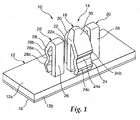
- Fig. 1 is a perspective view of an article support 10 according to an embodiment of the present invention
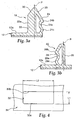
- Figs. 2(a) - 2(c) are a front view, a side view and a plan view of the article support 10, respectively
- Fig. 3(a) and 3(b) are different cross-sectional views of the article support 10.
- the article support 10 comprises a base 12 and a mount section 14 provided on the base 12.
- the article support 10 having the base 12 and the mount section 14 is integrally formed of a resin material such as nylon, polybutylene terephthalate, polyacetal and the like.
- the base 12 is a plate-like element that is rectangular when viewed from top and that has a top surface 12a and a back surface 12b, which are substantially flat and extend parallel to each other.
- An adhesive layer such as, for example, pressure sensitive adhesive double coated tape 16 for fastening an article to be supported may be disposed on the back surface 12b of the base 12.
- the mount section 14 comprises a first engaging element 18 standing vertically on the top surface 12a of the base 12, and a second engaging element 20 standing vertically on the top surface 12a of the base 12.
- the first engaging element 18 has a pillar 22 that protrudes from the base top surface 12a, and a first hook 24 that extends from the pillar 22 so that it can be displaced elastically.
- the second engaging element 20 has a pillar 26 that protrudes from the base top surface 12a, and a second hook 28 that extends from the pillar 26 so that it can be displaced elastically.
- the first hook 24 of the first engaging element 18 and the second hook 28 of the second engaging element 20 can be displaced elastically independently of each other and are disposed on the base top surface 12a on the sides opposite to each other with respect to the pillars 22 and 26.
- the pillar 22 of the first engaging element 18 and the pillar 26 of the second engaging element 20 are disposed on the base 12 so that they are separated from each other.
- the first engaging element 18 and the second engaging element 20 are formed on the base 12 as components that are independent of each other.
- one piece of the first engaging element 18 is mounted substantially at the center of the base top surface 12a and a pair of the second engaging elements 20 are mounted on both sides of the first engaging element 18 in the longitudinal direction of the base.
- the first hook 24 of the first engaging element 18 and each second hook 28 of the both second engaging elements 20 are formed on the base 12 so that they project in the directions opposite to each other with respect to an assumed plane P connecting between the respective pillars 22 and 26 ( Fig. 2(a) ).
- the pillar 22 of the first engaging element 18 comprises a rib 22a that extends substantially across the entire height on the side opposite to the first hook 24 (that is, on the same side of the second hooks 28 of the second engaging elements 20). It provides the pillar 22 with stiffness sufficient to bear a specific load (for example, a weight of the supported article) without bend.
- the rib 22a of the pillar 22 acts as a load bearing element that is engaged with an object to bear the load such as the weight of the object fastened to the base back surface 12b on such object when the mount section 14 is attached to the object properly, as described later.
- the first hook 24 of the first engaging element 18 is separated from the pillar 22 and extends in a serpentine manner so that it is supported at its both ends between the distal end of the pillar 22 and the top surface 12a of the base 12. Therefore, the first hook 24 can be displaced elastically so that it is moved toward or away from the pillar 22.
- a recess 24a is formed at the center in the longitudinal direction where the first hook 24 is separated from the pillar 22 and a pair of protuberances 24b and 24c are formed on the both sides of the recess 24a in the longitudinal direction.
- the recess 24a and the protuberance 24b on the distal side of the first hook 24 act as engagement maintaining elements that are engaged with an object to fixedly hold the article support 10 on the object when the mount section 14 is attached to the object properly, as described later.
- the recess 24a and the protuberance 24c on the base side of the first hook 24 act as spacer elements that are engaged with an object to define a predetermined minimum distance between the base 12 and the object when the mount section 14 is attached to the object properly, as described later.
- each second engaging element 20 does not have a rib and has such stiffness that the pillar 26 itself is more flexible than the pillar 22 of the first engaging element 18 but it cannot be bent easily.
- the pillar 26 is disposed at a position where it is not engaged with an object when the mount section 14 is attached to the object properly, as described later.
- the second hook 28 of each second engaging element 20 is separated from the pillar 26 and extends in a serpentine manner so that it is supported at its both ends between the distal end of the pillar 26 and the top surface 12a of the base 12. Therefore, the second hook 28 can be displaced elastically so that it is moved toward or away from the pillar 26.
- a recess 28a is formed at the center in the longitudinal direction where the second hook 28 is separated from the pillar 26 and a pair of protuberances 28b and 28c are formed on the both sides of the recess 28a in the longitudinal direction.
- the recess 28a and the protuberance 28b on the distal side of the second hook 28 act as engagement maintaining elements that are engaged with an object to fixedly hold the article support 10 on the object when the mount section 14 is attached to the object properly, as described later.
- the recess 28a and the protuberance 28c on the base side of the second hook 28 act as spacer elements that are engaged with an object to define a predetermined minimum distance between the base 12 and the object when the mount section 14 is attached to the object properly, as described later.
- the distance from the assumed plane P to the outward end face of the rib 22a of the pillar 22 of the first engaging element 18 is substantially equal to the distance from the assumed plane P to the outward end face of the recess 28a of the second hook 28 of each second engaging element 20 (the end face on the side separated from the pillar 26) and, at the same time, smaller than the distances to the outward end faces of the protuberances 28b and 28c of each second hook 28.
- the recess 24a and the protuberances 24b and 24c of the first hook 24 of the first engaging element 18 are disposed at the heights from the base top surface 12a that are substantially equal to the recess 28a and the protuberances 28b and 28c of the second hook 28 of each second engaging element 20, respectively.
- the pillar 22 of the first engaging element 18 on the base 12 protrudes higher than the pillars 26 of the both second engaging elements 20. Then, in the distal region of the pillar 22 and the first hook 24 where these elements are joined together, a plurality of guide faces 30 are formed for guiding the first hook 24 and the second hooks 28 to the positions where they are engaged with an object by contacting the object while the mount section 14 is attached to the object.
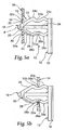
- the article support 10 is fixedly attached via the mount section 14 to a thin plate-like object 34 having a substantially rectangular or elliptical opening 32.
- the operation for attaching the article support 10 is performed by engaging the first and second engaging elements 18 and 20 of the mount section 14 into the opening 32 of the object 34.
- the opening 32 of the object 34 is shaped so that its minor axis L1 is substantially equal to the distance ⁇ between the outward end face of the rib 22a of the pillar 22 and the outward end face of the recess 24a of the first hook 24 in the first engaging element 18 of the article support 10 ( Fig.
- the first and second engaging elements 18 and 20 are inserted into the opening 32 by applying a pressing force to the base 12 in the direction toward the object 34.
- the outward end faces of the rib 22a and the first hook 24 of the first engaging element 18 are pressed against a pair of longer edges 32a and 32b of the opening 32, respectively.
- the first hook 24 is pressed by one of the longer edges of the opening 32 (the longer edge 32b in the figures) and bent elastically in the direction toward the pillar 22 and, then, restored elastically to receive the longer edge 32b in the recess 24a when the protuberance 24b on the distal side gets over the longer edge 32b ( Fig. 5(b) ).
- the rib 22a of the pillar 22 abuts against the other longer edge of the opening 32 (the longer edge 32a in the figures).
- each second engaging element 20 is pressed against the longer edge of the opening 32 on the side against which the pillar rib 22a of the first engaging element 18 abuts (the longer edge 32a in the figures).
- the pillar 26 of each second engaging element 20 is disposed apart from the other longer edge of the opening 32 (the longer edge 32b in the figures).
- each second hook 28 is pressed by the longer edge of the opening 32 (the longer edge 32a in the figures) and bent elastically in the direction toward the pillar 26 and, then, restored elastically to receive the longer edge 32a in the recess 28a when the protuberance 28b on the distal side gets over the longer edge 32a ( Fig. 5(b) ).
- the pressing force to the base 12 for engaging the first and second engaging elements 18 and 20 into the opening 32 is released.
- the protuberances 24b and 28b on the distal side of the first hook 24 and the second hooks 28 hold the article support 10 on the object 34 so that the article support 10 does not fall off the opening 32.
- the protuberances 24c and 28c on the base side of the first hook 24 and the second hooks 28 define a predetermined distance between the base 12 and the object 34.
- the article support 10 is fixedly held in the opening 32 of the object 34 and attached to the object 34 by cooperation between the first hook 24 of the first engaging element 18 and the second hooks 28 of the pair of the second engaging elements 20.
- the article support 10 is substantially maintained in a stationary manner in the direction of the minor axis L1 of the opening 32 by engaging the rib 22a of the pillar 22 and the first hook 24 of the first engaging element 18 with the longer edges 32a and 32b of the opening 32 of the object 34 at the same time, respectively.
- the second hooks 28 of the second engaging elements 20 disposed on the both sides of the first engaging element 18 are engaged with one of the longer edges of the opening 32 of the object 34 (the longer edge 32a in the figures) and act so as to prevent the first engaging element 18 from being rotated in the opening 32. Therefore, the article support 10 can be attached to the opening 32 of the object 34 stably without play.
- the relationship between the article support 10 and the object 34 shown in the figures is defined for applications in which the article support 10 is allowed to be moved in the direction of the major axis L2 of the opening 32, the article support 10 can also be secured in the direction of the major axis L2 by appropriately defining the dimensional relationship between them.
- the rib 22a of the pillar 22 of the first engaging element 18 is oriented so that it is disposed on the front side when viewed in the direction of the load.
- the engagement maintaining function can be exhibited stably because the pillar 22 of the first engaging element 18 bears the load properly by its own stiffness and, on the other hand, the load is not applied to the first hook 24 of the first engaging element 18.
- the second hooks 28 of the second engaging elements 20 can also exhibit the engaging maintaining function while they bear their share of the load.
- the positional displacement of the article support 10 with respect to the article can be prevented because the article support 10 can be fixedly held in the opening 32 of the object 34 by the first and second hooks 24 and 28 stably and, further, the load concentration on the first engaging element 18 and, thus, the stress concentration on the pressure sensitive adhesive double coated tape 16 (the adhesive layer) can be avoided.
- the load bearing construction provided on the object 34 accordingly for allowing the mount section 14 to exhibit the load bearing function is constructed by the edges of the opening 32, which is formed as an indispensable element for engagement with the first and second hooks 24 and 28, versatility is imparted to the article support 10 so that it is not necessary to provide the object 34 with any special load bearing construction.
- the first and second engaging elements 18 and 20 may be inserted into the opening 32 while the assumed plane P on the base 12 of the article support 10 is still not oriented substantially in parallel with the major axis L2 of the opening 32 of the object 34.
- the first engaging element 18 of the article support 10 is inserted into the opening 32, either one of the second engaging elements 20 can be engaged with one of the longer edges of the object 34 (the longer edge 32a in the figures) while its second hook 28 is bent considerably.
- the mount section 14 can show adaptability to a certain error range wherein at least one of the second hooks 28 can cooperate with the first hook 24 to fixedly hold the article support 10 in the opening 32 of the object stably.
- the guiding faces 30 of the first engaging element 18, which is inserted into the opening 32 earlier make contact with the edges of the opening 32 and slide thereon as appropriate so as to automatically guide the first hook 24 and the second hooks 28 to the positions where they are engaged with the longer edges 32a and 32b of the opening 32.
- the positioning construction provided on the object 34 accordingly for allowing the guiding faces 30 of the first engaging element 18 to exhibit the guiding function is constructed by the edges of the opening 32, which is formed as an indispensable element for engagement with the first and second hooks 24 and 28, versatility is imparted to the article support 10 so that it is not necessary to provide the object 34 with any special positioning construction.
- the article support 10 having the configuration as described above achieves a remarkable effect particularly in applications where the base 12 is fastened to the article to be supported in advance and the article support 10 is attached to the object 34 along with the article routinely.
- the article support 10 can preferably be used as a support for temporal fixing during curing of adhesive when a stationary window glass for a car is bonded to a window frame of a car body.
- the stationary window glass of the car is secured to the window frame of the car body in an airtight manner via thermosetting adhesive (sealant) over an entire edge of the glass panel, wherein it is required to fixedly hold the glass panel by using the support for temporal fixing so that the glass panel is not moved by vibrations due to other manufacturing operations, air pressure variations within the cabin, and the like till the adhesive is cured.
- thermosetting adhesive silant
- thermosetting adhesive 38 in an uncured state is applied in a strip-like manner along the outer edge of one surface (the surface toward the inside of the car body) of the glass panel 36 acting as the article to be supported and the article supports 10 are fastened via pressure sensitive adhesive double coated tape 16 disposed on the base back surfaces 12b to a plurality of predetermined positions (the positions corresponding to the plurality of openings 32 of the flange 34) in the inside and in the neighborhood of the thermosetting adhesive 38.
- the mount section 14 of each article support 10 is in the condition in which the first and second engaging elements 18 and 20 are projected from the surface of the glass panel 36 to a height preferably exceeding the thermosetting adhesive 38 ( Fig. 6 ).
- an adhesive flow preventing element called a dam rubber may further be secured to the glass panel 36 on the lower side in the direction of gravity.
- the positions for temporarily fixing the glass panel 36 on the window frame of the car body are determined at least along the flange 34 on the topside of the window frame of the car body so as to effectively bear the gravity applied to the glass panel 36.
- the flange 34 of the window frame of the car body typically extends in a narrow width along the contour of the window frame and, in the limited attachment area, it is required to attach the article supports 10 to the flange 34 with sufficient mechanical strength.
- each article support 10 is oriented so that the first and second engaging elements 18 and 20 thereof are aligned along the major axis of the flange openings 32 and so that the rib 22a of the pillar 22 of the first engaging element 18 is positioned on the lower side in the direction of gravity ( Fig. 6 ).
- the glass panel 36 on which a predetermined number of the article supports 10 are fastened at predetermined positions, is lifted up manually or by machine (for example, by robot) and, then, the mount sections 14 of these article supports 10 are aligned with the corresponding openings 32 provided in the flange 34 and inserted thereinto.
- each article support 10 is somewhat offset from the corresponding opening 32, with the help of the self-positioning effect exhibited by the guiding faces 30 of the first engaging element 18 of each article support 10, the first and second hooks 24 and 28 of each article support 10 are automatically guided to the positions where they are engaged with the longer edges 32a and 32b of the opening 32 so that the position of the glass panel 36 with respect to the flange 34 is corrected, as described above.
- each article support 10 is attached to the flange 34 defining a predetermined distance between the base 12 and the flange 34 by cooperation between the first hook 24 of the first engaging element 18 and at least one of the second hooks 28 of the second engaging elements 20 as described above and the glass panel 36 is temporarily fixed at a predetermined position of the window frame of the car body ( Fig. 7 ).
- the uncured thermosetting adhesive 38 (as well as the dam rubber, if used) tends to urge the glass panel 36 in the direction to move away from the flange 34 by its own resiliency. Therefore, the protuberances 24b and 28b on the distal side of the first hook 24 and the second hooks 28 of each article support 10 are engaged with the longer edges 32a and 32b of the flange 34, in particular, at the rising face 24d of the protuberance 24b and the inclined face 28d of the protuberance 28b, to fixedly hold the article support 10 on the object 34 so that it does not fall off the opening 32 ( Fig. 7 ).
- the first and second engaging elements 18 and 20 which are aligned along the major axis of the opening 32 of the flange 34, bear the weight of the glass panel 36 in a distributed manner on the rib 22a of the pillar 22 mainly and on the second hooks 28 in an auxiliary manner. Therefore, the first and second hooks 24 and 28 of the first and second engaging elements 18 and 20 are engaged with the longer edges 32a and 32b of the flange opening 32 stably so as to fixedly hold the article support 10 on the flange 34 without being bent by a load such as the weight of the glass panel 36 and the like.
- the article support 10 bears the load such as the weight of the glass panel 36 and the like, as the load concentration on the first engaging element 18 and, consequently, the stress concentration on the pressure sensitive adhesive double coated tape 16 (the adhesive layer) can be avoided, the positional displacement of each article support 10 with respect to the glass panel 36 can be prevented effectively.
- the mount sections 14 of the article supports 10 have adaptability to a certain error range as described above, if only each article support 10 on the glass panel 36 is aligned with the corresponding opening 32 of the flange 34 with high accuracy, the mount sections 14 can be inserted into the openings 32 automatically so that the first and second hooks 24 and 28 can be engaged with the longer edges 32a and 32b of the openings 32 stably, even when there is a relative positional offset between the article support 10 and the opening 32 in the rotational direction.
- first and second hooks 24 and 28 of the first and second engaging elements 18 and 20 of the article support 10 ensure a predetermined minimum distance between the flange 34 and the glass panel 36 by their spacer elements 24a, 24c, 28a and 28c. Therefore, the thermosetting adhesive 38 disposed along the outer edge of the glass panel 36 in advance can be cured stably between the flange 34 and the glass panel 36 so as to fasten them to each other in an airtight manner.
- At least one of the first and second hooks 24 and 28 of the first and second engaging elements 18 and 20 may be supported by the pillars 22 and 26 in a cantilevered manner.
- a hook-and-loop fastener structure in which a plurality of headed elements stand on the base back surface 12b may be adopted in place of the pressure sensitive adhesive double coated tape 16.
- the article supports 10 are attached to the openings 32 of the object 34 in advance solely when these are used. Also in the case of such article supports, the article supports can be attached to the object stably thanks to the effect of the mount sections having a distinctive configuration as described above.
Landscapes
- Engineering & Computer Science (AREA)
- General Engineering & Computer Science (AREA)
- Mechanical Engineering (AREA)
- Connection Of Plates (AREA)
- Supports Or Holders For Household Use (AREA)
- Insertion Pins And Rivets (AREA)
- Slide Fasteners, Snap Fasteners, And Hook Fasteners (AREA)
- Manipulator (AREA)
- Die Bonding (AREA)
- Packages (AREA)
- Packaging Frangible Articles (AREA)
- Vibration Prevention Devices (AREA)
Claims (7)
- Support d'article (10) comprenant une base (12) et une section de montage (14) pour supporter un article fixé à ladite base (12) sur un objet en attachant ladite section de montage (14) à l'objet, ladite section de montage comprenant :un premier élément d'engagement (18) comprenant un montant (22) faisant saillie depuis ladite base (12) et un premier crochet (24) s'étendant depuis ledit montant (22) d'une manière déplaçable élastiquement ;deux deuxièmes éléments d'engagement (20) disposés sur des côtés opposés dudit premier élément d'engagement (18), chaque deuxième élément d'engagement (20) comprenant un montant (26) faisant saillie depuis ladite base (12) et un deuxième crochet (28) s'étendant depuis ledit montant (26) d'une manière déplaçable élastiquement, ledit montant (22) dudit premier élément d'engagement (18) et ledit montant (26) dudit deuxième élément d'engagement (20) étant écartés l'un de l'autre sur ladite base (12),dans lequel ledit premier crochet (24) et ledit deuxième crochet (28) sont déplaçables élastiquement indépendamment l'un de l'autre, et sont disposés à l'opposé l'un de l'autre par rapport auxdits montants (22, 26).
- Support d'article selon la revendication 1, dans lequel ledit montant (22) dudit premier élément d'engagement (18) fait saillie plus haut que lesdits montants (26) desdits deuxièmes éléments d'engagement (20) sur ladite base (12).
- Support d'article selon la revendication 2, dans lequel ledit montant (22) dudit premier élément d'engagement (18) comprend une face de guidage (30) qui est capable d'entrer en contact avec l'objet pendant une opération de fixation de ladite section de montage à l'objet afin de guider ledit premier crochet (24) et lesdits deuxièmes crochets (28) vers une position pour l'engagement avec l'objet.
- Support d'article selon l'une quelconque des revendications 1 à 3, dans lequel, lorsque ladite section de montage est attachée à l'objet, ledit montant (22) et ledit premier crochet (24) dudit premier élément d'engagement (18) sont engagés avec l'objet tandis que lesdits montants (26) desdits deuxièmes éléments d'engagement (20) ne sont pas engagés avec ledit objet.
- Support d'article selon l'une quelconque des revendications 1 à 4, dans lequel, lorsque ladite section de montage est attachée à l'objet, ledit montant (22) dudit premier élément d'engagement (18) porte une charge sur l'objet, et ledit premier crochet (24) et lesdits deuxièmes crochets (28) sont engagés avec l'objet de façon à maintenir fixement le support d'article sur l'objet.
- Support d'article selon l'une quelconque des revendications 1 à 5, dans lequel au moins un dudit premier crochet (24) et desdits deuxièmes crochets (28) est supporté à ses deux extrémités entre ladite base (12) et ledit montant (22, 26).
- Support d'article selon l'une quelconque des revendications 1 à 6, dans lequel au moins un dudit premier crochet (24) et desdits deuxièmes crochets (28) comprend un élément d'écartement pour définir une distance minimum prédéterminée entre ladite base (12) et ledit objet lorsque ladite section de montage est attachée à l'objet.
Applications Claiming Priority (2)
| Application Number | Priority Date | Filing Date | Title |
|---|---|---|---|
| JP2004145375A JP4683858B2 (ja) | 2004-05-14 | 2004-05-14 | 物品支持具 |
| PCT/US2005/016413 WO2005113989A1 (fr) | 2004-05-14 | 2005-05-11 | Support d'article |
Publications (2)
| Publication Number | Publication Date |
|---|---|
| EP1751433A1 EP1751433A1 (fr) | 2007-02-14 |
| EP1751433B1 true EP1751433B1 (fr) | 2009-07-08 |
Family
ID=34969454
Family Applications (1)
| Application Number | Title | Priority Date | Filing Date |
|---|---|---|---|
| EP05747631A Not-in-force EP1751433B1 (fr) | 2004-05-14 | 2005-05-11 | Support d'article |
Country Status (10)
| Country | Link |
|---|---|
| US (1) | US7686266B2 (fr) |
| EP (1) | EP1751433B1 (fr) |
| JP (1) | JP4683858B2 (fr) |
| CN (1) | CN1985095B (fr) |
| AT (1) | ATE435980T1 (fr) |
| BR (1) | BRPI0511012B1 (fr) |
| CA (1) | CA2566714C (fr) |
| DE (1) | DE602005015316D1 (fr) |
| TW (1) | TWI277545B (fr) |
| WO (1) | WO2005113989A1 (fr) |
Families Citing this family (25)
| Publication number | Priority date | Publication date | Assignee | Title |
|---|---|---|---|---|
| JP4725365B2 (ja) * | 2006-03-01 | 2011-07-13 | 日産自動車株式会社 | 係合固定構造および係合固定方法 |
| JP5159054B2 (ja) * | 2006-07-13 | 2013-03-06 | 日本トムソン株式会社 | 直動転がり案内ユニット |
| JP2008240887A (ja) * | 2007-03-27 | 2008-10-09 | Daikyo Nishikawa Kk | 取付部材の取付構造 |
| CN101835648B (zh) | 2007-10-24 | 2013-03-27 | 皮尔金顿汽车德国有限公司 | 定心销 |
| US20090126168A1 (en) * | 2007-11-15 | 2009-05-21 | Kobe James J | Multi-Angle Pop-In Mechanical Fastener |
| US20090261613A1 (en) * | 2008-04-16 | 2009-10-22 | International Automotive Components Group North America, Inc. | Trim component with retention tabs |
| FR2941174B1 (fr) * | 2009-01-21 | 2012-12-14 | Peugeot Citroen Automobiles Sa | Dispositif pour fixer de facon etanche un vitrage en matiere plastique transparente sur une ouverture de la structure d'un vehicule automobile. |
| US7976094B2 (en) * | 2009-03-04 | 2011-07-12 | Zeledyne, Llc | Folding locator pin for glass panels |
| US9812684B2 (en) | 2010-11-09 | 2017-11-07 | GM Global Technology Operations LLC | Using elastic averaging for alignment of battery stack, fuel cell stack, or other vehicle assembly |
| EP2638199B1 (fr) * | 2010-11-12 | 2016-09-07 | Arçelik Anonim Sirketi | Machine à laver/sécher avec un élément de raccordement |
| US11022343B2 (en) * | 2011-09-02 | 2021-06-01 | Pv Solutions, Llc | Mounting system for photovoltaic arrays |
| GB201120340D0 (en) | 2011-11-25 | 2012-01-04 | Pilkington Group Ltd | Automotive glazing |
| JP5742691B2 (ja) * | 2011-11-30 | 2015-07-01 | トヨタ自動車株式会社 | テザークリップおよびそれを備えたガーニッシュ取付装置 |
| DE102012010893A1 (de) * | 2012-06-01 | 2013-12-05 | Gottlieb Binder Gmbh & Co. Kg | Befestigungssystem |
| JP6036060B2 (ja) * | 2012-09-13 | 2016-11-30 | トヨタ車体株式会社 | 部品の掛止構造 |
| DE102013009091A1 (de) | 2013-05-28 | 2014-12-04 | Gottlieb Binder Gmbh & Co. Kg | Verfahren zum Herstellen eines Verbindungsteils, nach dem Verfahren hergestelltes Verbindungsteil, Werkzeug zum Herstellen eines solchen Verbindungsteils und Befestigungssystem mit einem derartigen Verbindungsteil |
| JP6135596B2 (ja) * | 2014-05-09 | 2017-05-31 | トヨタ自動車株式会社 | 車両用取付構造 |
| US20150375798A1 (en) * | 2014-06-30 | 2015-12-31 | GM Global Technology Operations LLC | Elastically averaged alignment systems and methods |
| US9429176B2 (en) * | 2014-06-30 | 2016-08-30 | GM Global Technology Operations LLC | Elastically averaged alignment systems and methods |
| JP6522324B2 (ja) * | 2014-12-04 | 2019-05-29 | Agcオートモーティブウィンドウシステムズ株式会社 | ガラス支持具 |
| US9758110B2 (en) | 2015-01-12 | 2017-09-12 | GM Global Technology Operations LLC | Coupling system |
| US10288099B2 (en) * | 2015-12-04 | 2019-05-14 | Ford Global Technologies, Llc | Attachment feature for securing two parallel workpieces together |
| EP3413688B1 (fr) * | 2017-06-09 | 2021-08-11 | Electrolux Appliances Aktiebolag | Élément de raccordement d'une bobine d'induction à un support de bobine d'une table de cuisson par induction |
| CN111520587A (zh) * | 2020-04-21 | 2020-08-11 | 河北工业职业技术学院 | 一种基于大数据的课堂教学管理系统 |
| JP7294262B2 (ja) * | 2020-07-13 | 2023-06-20 | トヨタ自動車株式会社 | 車両 |
Family Cites Families (19)
| Publication number | Priority date | Publication date | Assignee | Title |
|---|---|---|---|---|
| JPS6020186U (ja) * | 1983-07-19 | 1985-02-12 | 北川工業株式会社 | 固定具 |
| JPH0617347Y2 (ja) * | 1984-07-24 | 1994-05-02 | 北川工業株式会社 | 板材保持具 |
| JPS62191910U (fr) * | 1986-05-28 | 1987-12-07 | ||
| US4739543A (en) * | 1987-06-08 | 1988-04-26 | Ford Motor Company | Push pin retainer |
| JPH03260256A (ja) | 1990-03-08 | 1991-11-20 | Naka Ind Ltd | 手摺及びその取付け工法 |
| JP2512360Y2 (ja) * | 1990-08-24 | 1996-10-02 | 株式会社ニフコ | 板状物の係合具 |
| JPH0632132A (ja) | 1992-07-20 | 1994-02-08 | Nippondenso Co Ltd | 減衰力可変ショックアブソーバ及びその制御装置 |
| JP3476219B2 (ja) | 1993-07-30 | 2003-12-10 | 株式会社ニデック | 眼屈折力測定装置 |
| CA2129773C (fr) | 1993-09-02 | 2007-05-01 | Michael Klaus | Derives d'acides carboxyliques aromatiques |
| JP3260256B2 (ja) * | 1995-05-16 | 2002-02-25 | 株式会社ニフコ | ガラスストッパー |
| JP3116793B2 (ja) | 1995-11-24 | 2000-12-11 | 三菱自動車工業株式会社 | ウインドガラスの仮止め用クリップ |
| US5833480A (en) * | 1996-07-03 | 1998-11-10 | Illinois Tool Works Inc. | Standoff ground connector |
| JP3768308B2 (ja) * | 1996-11-15 | 2006-04-19 | 大和化成工業株式会社 | ガーニッシュクリップ |
| US6305892B1 (en) * | 1997-08-12 | 2001-10-23 | Zenith Electronics Corporation | Fastening system for speaker grilles |
| EP1046825A3 (fr) * | 1999-04-23 | 2002-04-17 | Piolax Inc. | Dispositif de fixation d'une pièce sur un panneau à travers un orifice traversant et support muni d'un tel dispositif |
| JP3772253B2 (ja) * | 1999-04-23 | 2006-05-10 | 株式会社パイオラックス | 止着具 |
| US6471313B1 (en) * | 1999-12-13 | 2002-10-29 | Hoshizaki Denki Co., Ltd. | Corner cover mounting structure for heat-insulated housing for use in refrigerator |
| JP3715232B2 (ja) * | 2001-11-19 | 2005-11-09 | 本田技研工業株式会社 | ピラーガーニッシュ締結構造 |
| US6824197B2 (en) * | 2003-03-20 | 2004-11-30 | Newfrey Llc | Panel retention device |
-
2004
- 2004-05-14 JP JP2004145375A patent/JP4683858B2/ja not_active Expired - Lifetime
-
2005
- 2005-05-11 WO PCT/US2005/016413 patent/WO2005113989A1/fr active Application Filing
- 2005-05-11 CN CN200580023639.0A patent/CN1985095B/zh active Active
- 2005-05-11 US US11/569,005 patent/US7686266B2/en active Active
- 2005-05-11 DE DE602005015316T patent/DE602005015316D1/de active Active
- 2005-05-11 AT AT05747631T patent/ATE435980T1/de not_active IP Right Cessation
- 2005-05-11 CA CA2566714A patent/CA2566714C/fr active Active
- 2005-05-11 EP EP05747631A patent/EP1751433B1/fr not_active Not-in-force
- 2005-05-11 BR BRPI0511012-2A patent/BRPI0511012B1/pt not_active IP Right Cessation
- 2005-05-13 TW TW094115674A patent/TWI277545B/zh not_active IP Right Cessation
Also Published As
| Publication number | Publication date |
|---|---|
| US7686266B2 (en) | 2010-03-30 |
| TWI277545B (en) | 2007-04-01 |
| BRPI0511012A (pt) | 2007-11-27 |
| JP4683858B2 (ja) | 2011-05-18 |
| JP2005325942A (ja) | 2005-11-24 |
| DE602005015316D1 (de) | 2009-08-20 |
| US20080169388A1 (en) | 2008-07-17 |
| ATE435980T1 (de) | 2009-07-15 |
| CA2566714A1 (fr) | 2005-12-01 |
| CA2566714C (fr) | 2012-08-14 |
| CN1985095B (zh) | 2010-11-17 |
| CN1985095A (zh) | 2007-06-20 |
| WO2005113989A1 (fr) | 2005-12-01 |
| EP1751433A1 (fr) | 2007-02-14 |
| TW200606040A (en) | 2006-02-16 |
| BRPI0511012B1 (pt) | 2018-06-12 |
Similar Documents
| Publication | Publication Date | Title |
|---|---|---|
| EP1751433B1 (fr) | Support d'article | |
| CA2702112C (fr) | Ensemble de joint de panneau interieur a encliquetage | |
| EP0468753A1 (fr) | Dispositif de montage pour boîtier de lampe dans un véhicule | |
| US4389069A (en) | Method of and a device for fixing a window molding onto a windowpane | |
| US6944917B2 (en) | Clip for mounting weatherstrip | |
| CN109555763B (zh) | 夹具安装座 | |
| US9796345B2 (en) | Clip and connecting structure using clip | |
| US20040012218A1 (en) | Clip for attaching a corner cladding to a vehicle | |
| JPH0840152A (ja) | ルーフドリップモールの係止クリップ | |
| JP2587516Y2 (ja) | 車両用ウインドガラス取付調整装置 | |
| JPS637695Y2 (fr) | ||
| KR200141961Y1 (ko) | 차량용 클립구조 | |
| JPH07332322A (ja) | 部品の取付構造 | |
| JPH08318733A (ja) | ウィンドウガラス取り付け装置 | |
| JPH0333561Y2 (fr) | ||
| JP3890732B2 (ja) | 車両用ウィンドガラスガーニッシュ固定構造 | |
| JPH0135926Y2 (fr) | ||
| JPH0732195Y2 (ja) | 自動車用ウインドシールドモールの係止具 | |
| JP2538059Y2 (ja) | モールの取付構造 | |
| JPS6111043Y2 (fr) | ||
| KR100551176B1 (ko) | 위치 보정용 훼스너 브라켓의 결합구조 | |
| JP5029567B2 (ja) | 接着式ウインドガラスの仮止め構造 | |
| JPH0426248Y2 (fr) | ||
| JP2579810Y2 (ja) | ベルトモール用クリップ | |
| JP2004351065A (ja) | 物品支持具 |
Legal Events
| Date | Code | Title | Description |
|---|---|---|---|
| PUAI | Public reference made under article 153(3) epc to a published international application that has entered the european phase |
Free format text: ORIGINAL CODE: 0009012 |
|
| 17P | Request for examination filed |
Effective date: 20061130 |
|
| AK | Designated contracting states |
Kind code of ref document: A1 Designated state(s): AT BE BG CH CY CZ DE DK EE ES FI FR GB GR HU IE IS IT LI LT LU MC NL PL PT RO SE SI SK TR |
|
| DAX | Request for extension of the european patent (deleted) | ||
| GRAP | Despatch of communication of intention to grant a patent |
Free format text: ORIGINAL CODE: EPIDOSNIGR1 |
|
| GRAJ | Information related to disapproval of communication of intention to grant by the applicant or resumption of examination proceedings by the epo deleted |
Free format text: ORIGINAL CODE: EPIDOSDIGR1 |
|
| GRAP | Despatch of communication of intention to grant a patent |
Free format text: ORIGINAL CODE: EPIDOSNIGR1 |
|
| GRAS | Grant fee paid |
Free format text: ORIGINAL CODE: EPIDOSNIGR3 |
|
| GRAA | (expected) grant |
Free format text: ORIGINAL CODE: 0009210 |
|
| AK | Designated contracting states |
Kind code of ref document: B1 Designated state(s): AT BE BG CH CY CZ DE DK EE ES FI FR GB GR HU IE IS IT LI LT LU MC NL PL PT RO SE SI SK TR |
|
| REG | Reference to a national code |
Ref country code: GB Ref legal event code: FG4D |
|
| REG | Reference to a national code |
Ref country code: CH Ref legal event code: EP |
|
| REG | Reference to a national code |
Ref country code: IE Ref legal event code: FG4D |
|
| REF | Corresponds to: |
Ref document number: 602005015316 Country of ref document: DE Date of ref document: 20090820 Kind code of ref document: P |
|
| PG25 | Lapsed in a contracting state [announced via postgrant information from national office to epo] |
Ref country code: SI Free format text: LAPSE BECAUSE OF FAILURE TO SUBMIT A TRANSLATION OF THE DESCRIPTION OR TO PAY THE FEE WITHIN THE PRESCRIBED TIME-LIMIT Effective date: 20090708 |
|
| NLV1 | Nl: lapsed or annulled due to failure to fulfill the requirements of art. 29p and 29m of the patents act | ||
| PG25 | Lapsed in a contracting state [announced via postgrant information from national office to epo] |
Ref country code: LT Free format text: LAPSE BECAUSE OF FAILURE TO SUBMIT A TRANSLATION OF THE DESCRIPTION OR TO PAY THE FEE WITHIN THE PRESCRIBED TIME-LIMIT Effective date: 20090708 Ref country code: IS Free format text: LAPSE BECAUSE OF FAILURE TO SUBMIT A TRANSLATION OF THE DESCRIPTION OR TO PAY THE FEE WITHIN THE PRESCRIBED TIME-LIMIT Effective date: 20091108 Ref country code: FI Free format text: LAPSE BECAUSE OF FAILURE TO SUBMIT A TRANSLATION OF THE DESCRIPTION OR TO PAY THE FEE WITHIN THE PRESCRIBED TIME-LIMIT Effective date: 20090708 Ref country code: ES Free format text: LAPSE BECAUSE OF FAILURE TO SUBMIT A TRANSLATION OF THE DESCRIPTION OR TO PAY THE FEE WITHIN THE PRESCRIBED TIME-LIMIT Effective date: 20091019 Ref country code: AT Free format text: LAPSE BECAUSE OF FAILURE TO SUBMIT A TRANSLATION OF THE DESCRIPTION OR TO PAY THE FEE WITHIN THE PRESCRIBED TIME-LIMIT Effective date: 20090708 |
|
| PG25 | Lapsed in a contracting state [announced via postgrant information from national office to epo] |
Ref country code: NL Free format text: LAPSE BECAUSE OF FAILURE TO SUBMIT A TRANSLATION OF THE DESCRIPTION OR TO PAY THE FEE WITHIN THE PRESCRIBED TIME-LIMIT Effective date: 20090708 Ref country code: PL Free format text: LAPSE BECAUSE OF FAILURE TO SUBMIT A TRANSLATION OF THE DESCRIPTION OR TO PAY THE FEE WITHIN THE PRESCRIBED TIME-LIMIT Effective date: 20090708 |
|
| PG25 | Lapsed in a contracting state [announced via postgrant information from national office to epo] |
Ref country code: BG Free format text: LAPSE BECAUSE OF FAILURE TO SUBMIT A TRANSLATION OF THE DESCRIPTION OR TO PAY THE FEE WITHIN THE PRESCRIBED TIME-LIMIT Effective date: 20091008 Ref country code: PT Free format text: LAPSE BECAUSE OF FAILURE TO SUBMIT A TRANSLATION OF THE DESCRIPTION OR TO PAY THE FEE WITHIN THE PRESCRIBED TIME-LIMIT Effective date: 20091109 |
|
| PG25 | Lapsed in a contracting state [announced via postgrant information from national office to epo] |
Ref country code: CZ Free format text: LAPSE BECAUSE OF FAILURE TO SUBMIT A TRANSLATION OF THE DESCRIPTION OR TO PAY THE FEE WITHIN THE PRESCRIBED TIME-LIMIT Effective date: 20090708 Ref country code: RO Free format text: LAPSE BECAUSE OF FAILURE TO SUBMIT A TRANSLATION OF THE DESCRIPTION OR TO PAY THE FEE WITHIN THE PRESCRIBED TIME-LIMIT Effective date: 20090708 Ref country code: DK Free format text: LAPSE BECAUSE OF FAILURE TO SUBMIT A TRANSLATION OF THE DESCRIPTION OR TO PAY THE FEE WITHIN THE PRESCRIBED TIME-LIMIT Effective date: 20090708 Ref country code: EE Free format text: LAPSE BECAUSE OF FAILURE TO SUBMIT A TRANSLATION OF THE DESCRIPTION OR TO PAY THE FEE WITHIN THE PRESCRIBED TIME-LIMIT Effective date: 20090708 |
|
| PLBE | No opposition filed within time limit |
Free format text: ORIGINAL CODE: 0009261 |
|
| STAA | Information on the status of an ep patent application or granted ep patent |
Free format text: STATUS: NO OPPOSITION FILED WITHIN TIME LIMIT |
|
| PG25 | Lapsed in a contracting state [announced via postgrant information from national office to epo] |
Ref country code: SK Free format text: LAPSE BECAUSE OF FAILURE TO SUBMIT A TRANSLATION OF THE DESCRIPTION OR TO PAY THE FEE WITHIN THE PRESCRIBED TIME-LIMIT Effective date: 20090708 Ref country code: BE Free format text: LAPSE BECAUSE OF FAILURE TO SUBMIT A TRANSLATION OF THE DESCRIPTION OR TO PAY THE FEE WITHIN THE PRESCRIBED TIME-LIMIT Effective date: 20090708 |
|
| 26N | No opposition filed |
Effective date: 20100409 |
|
| PG25 | Lapsed in a contracting state [announced via postgrant information from national office to epo] |
Ref country code: GR Free format text: LAPSE BECAUSE OF FAILURE TO SUBMIT A TRANSLATION OF THE DESCRIPTION OR TO PAY THE FEE WITHIN THE PRESCRIBED TIME-LIMIT Effective date: 20091009 |
|
| PG25 | Lapsed in a contracting state [announced via postgrant information from national office to epo] |
Ref country code: MC Free format text: LAPSE BECAUSE OF NON-PAYMENT OF DUE FEES Effective date: 20100531 |
|
| REG | Reference to a national code |
Ref country code: CH Ref legal event code: PL |
|
| GBPC | Gb: european patent ceased through non-payment of renewal fee |
Effective date: 20100511 |
|
| REG | Reference to a national code |
Ref country code: FR Ref legal event code: ST Effective date: 20110131 |
|
| PG25 | Lapsed in a contracting state [announced via postgrant information from national office to epo] |
Ref country code: CH Free format text: LAPSE BECAUSE OF NON-PAYMENT OF DUE FEES Effective date: 20100531 Ref country code: LI Free format text: LAPSE BECAUSE OF NON-PAYMENT OF DUE FEES Effective date: 20100531 |
|
| PG25 | Lapsed in a contracting state [announced via postgrant information from national office to epo] |
Ref country code: IT Free format text: LAPSE BECAUSE OF FAILURE TO SUBMIT A TRANSLATION OF THE DESCRIPTION OR TO PAY THE FEE WITHIN THE PRESCRIBED TIME-LIMIT Effective date: 20090708 |
|
| PG25 | Lapsed in a contracting state [announced via postgrant information from national office to epo] |
Ref country code: IE Free format text: LAPSE BECAUSE OF NON-PAYMENT OF DUE FEES Effective date: 20100511 |
|
| PG25 | Lapsed in a contracting state [announced via postgrant information from national office to epo] |
Ref country code: FR Free format text: LAPSE BECAUSE OF NON-PAYMENT OF DUE FEES Effective date: 20100531 |
|
| PG25 | Lapsed in a contracting state [announced via postgrant information from national office to epo] |
Ref country code: GB Free format text: LAPSE BECAUSE OF NON-PAYMENT OF DUE FEES Effective date: 20100511 |
|
| PG25 | Lapsed in a contracting state [announced via postgrant information from national office to epo] |
Ref country code: CY Free format text: LAPSE BECAUSE OF FAILURE TO SUBMIT A TRANSLATION OF THE DESCRIPTION OR TO PAY THE FEE WITHIN THE PRESCRIBED TIME-LIMIT Effective date: 20090708 |
|
| PG25 | Lapsed in a contracting state [announced via postgrant information from national office to epo] |
Ref country code: SE Free format text: LAPSE BECAUSE OF FAILURE TO SUBMIT A TRANSLATION OF THE DESCRIPTION OR TO PAY THE FEE WITHIN THE PRESCRIBED TIME-LIMIT Effective date: 20090708 Ref country code: HU Free format text: LAPSE BECAUSE OF FAILURE TO SUBMIT A TRANSLATION OF THE DESCRIPTION OR TO PAY THE FEE WITHIN THE PRESCRIBED TIME-LIMIT Effective date: 20100109 Ref country code: LU Free format text: LAPSE BECAUSE OF NON-PAYMENT OF DUE FEES Effective date: 20100511 |
|
| PG25 | Lapsed in a contracting state [announced via postgrant information from national office to epo] |
Ref country code: TR Free format text: LAPSE BECAUSE OF FAILURE TO SUBMIT A TRANSLATION OF THE DESCRIPTION OR TO PAY THE FEE WITHIN THE PRESCRIBED TIME-LIMIT Effective date: 20090708 |
|
| REG | Reference to a national code |
Ref country code: DE Ref legal event code: R082 Ref document number: 602005015316 Country of ref document: DE Representative=s name: ISARPATENT - PATENT- UND RECHTSANWAELTE BEHNIS, DE Ref country code: DE Ref legal event code: R082 Ref document number: 602005015316 Country of ref document: DE Representative=s name: ISARPATENT - PATENT- UND RECHTSANWAELTE BARTH , DE Ref country code: DE Ref legal event code: R082 Ref document number: 602005015316 Country of ref document: DE Representative=s name: ISARPATENT - PATENTANWAELTE- UND RECHTSANWAELT, DE Ref country code: DE Ref legal event code: R081 Ref document number: 602005015316 Country of ref document: DE Owner name: 3M INNOVATIVE PROPERTIES CO., ST. PAUL, US Free format text: FORMER OWNERS: 3M INNOVATIVE PROPERTIES CO., ST. PAUL, MINN., US; HONDA MOTOR CO., LTD., TOKYO, JP |
|
| PGFP | Annual fee paid to national office [announced via postgrant information from national office to epo] |
Ref country code: DE Payment date: 20190430 Year of fee payment: 15 |
|
| REG | Reference to a national code |
Ref country code: DE Ref legal event code: R119 Ref document number: 602005015316 Country of ref document: DE |
|
| PG25 | Lapsed in a contracting state [announced via postgrant information from national office to epo] |
Ref country code: DE Free format text: LAPSE BECAUSE OF NON-PAYMENT OF DUE FEES Effective date: 20201201 |