EP1749549B1 - Système de drainage de fluide cephalo-rachidien - Google Patents
Système de drainage de fluide cephalo-rachidien Download PDFInfo
- Publication number
- EP1749549B1 EP1749549B1 EP05016789A EP05016789A EP1749549B1 EP 1749549 B1 EP1749549 B1 EP 1749549B1 EP 05016789 A EP05016789 A EP 05016789A EP 05016789 A EP05016789 A EP 05016789A EP 1749549 B1 EP1749549 B1 EP 1749549B1
- Authority
- EP
- European Patent Office
- Prior art keywords
- liquor
- pressure
- pump
- drainage
- operating
- Prior art date
- Legal status (The legal status is an assumption and is not a legal conclusion. Google has not performed a legal analysis and makes no representation as to the accuracy of the status listed.)
- Active
Links
- 210000001175 cerebrospinal fluid Anatomy 0.000 title claims abstract description 84
- 238000001514 detection method Methods 0.000 claims description 5
- 230000003287 optical effect Effects 0.000 claims description 4
- 238000012544 monitoring process Methods 0.000 claims description 3
- 239000012530 fluid Substances 0.000 abstract description 15
- 238000000034 method Methods 0.000 abstract description 7
- 238000005259 measurement Methods 0.000 abstract description 3
- 210000004556 brain Anatomy 0.000 description 20
- 230000002572 peristaltic effect Effects 0.000 description 14
- 238000005086 pumping Methods 0.000 description 9
- 230000008569 process Effects 0.000 description 6
- 230000002490 cerebral effect Effects 0.000 description 5
- 239000007788 liquid Substances 0.000 description 4
- 210000003625 skull Anatomy 0.000 description 4
- 238000011156 evaluation Methods 0.000 description 3
- 230000008901 benefit Effects 0.000 description 2
- 238000009530 blood pressure measurement Methods 0.000 description 2
- 230000008878 coupling Effects 0.000 description 2
- 238000010168 coupling process Methods 0.000 description 2
- 238000005859 coupling reaction Methods 0.000 description 2
- 208000003906 hydrocephalus Diseases 0.000 description 2
- 230000002706 hydrostatic effect Effects 0.000 description 2
- XLYOFNOQVPJJNP-UHFFFAOYSA-N water Substances O XLYOFNOQVPJJNP-UHFFFAOYSA-N 0.000 description 2
- 206010022773 Intracranial pressure increased Diseases 0.000 description 1
- 208000007536 Thrombosis Diseases 0.000 description 1
- 230000001154 acute effect Effects 0.000 description 1
- 238000011511 automated evaluation Methods 0.000 description 1
- 230000005540 biological transmission Effects 0.000 description 1
- 230000015572 biosynthetic process Effects 0.000 description 1
- 239000008280 blood Substances 0.000 description 1
- 210000004369 blood Anatomy 0.000 description 1
- 230000036772 blood pressure Effects 0.000 description 1
- 238000011109 contamination Methods 0.000 description 1
- 230000002950 deficient Effects 0.000 description 1
- 230000001419 dependent effect Effects 0.000 description 1
- 230000036512 infertility Effects 0.000 description 1
- 238000007917 intracranial administration Methods 0.000 description 1
- 210000004705 lumbosacral region Anatomy 0.000 description 1
- 239000000463 material Substances 0.000 description 1
- 230000000474 nursing effect Effects 0.000 description 1
- 238000010926 purge Methods 0.000 description 1
- 230000001105 regulatory effect Effects 0.000 description 1
- 230000004044 response Effects 0.000 description 1
- 238000005096 rolling process Methods 0.000 description 1
- 230000035945 sensitivity Effects 0.000 description 1
- 230000002123 temporal effect Effects 0.000 description 1
- 238000012546 transfer Methods 0.000 description 1
- 210000003462 vein Anatomy 0.000 description 1
- 230000000007 visual effect Effects 0.000 description 1
Images
Classifications
-
- A—HUMAN NECESSITIES
- A61—MEDICAL OR VETERINARY SCIENCE; HYGIENE
- A61M—DEVICES FOR INTRODUCING MEDIA INTO, OR ONTO, THE BODY; DEVICES FOR TRANSDUCING BODY MEDIA OR FOR TAKING MEDIA FROM THE BODY; DEVICES FOR PRODUCING OR ENDING SLEEP OR STUPOR
- A61M27/00—Drainage appliance for wounds or the like, i.e. wound drains, implanted drains
- A61M27/002—Implant devices for drainage of body fluids from one part of the body to another
- A61M27/006—Cerebrospinal drainage; Accessories therefor, e.g. valves
-
- A—HUMAN NECESSITIES
- A61—MEDICAL OR VETERINARY SCIENCE; HYGIENE
- A61M—DEVICES FOR INTRODUCING MEDIA INTO, OR ONTO, THE BODY; DEVICES FOR TRANSDUCING BODY MEDIA OR FOR TAKING MEDIA FROM THE BODY; DEVICES FOR PRODUCING OR ENDING SLEEP OR STUPOR
- A61M1/00—Suction or pumping devices for medical purposes; Devices for carrying-off, for treatment of, or for carrying-over, body-liquids; Drainage systems
- A61M1/71—Suction drainage systems
- A61M1/73—Suction drainage systems comprising sensors or indicators for physical values
-
- A—HUMAN NECESSITIES
- A61—MEDICAL OR VETERINARY SCIENCE; HYGIENE
- A61M—DEVICES FOR INTRODUCING MEDIA INTO, OR ONTO, THE BODY; DEVICES FOR TRANSDUCING BODY MEDIA OR FOR TAKING MEDIA FROM THE BODY; DEVICES FOR PRODUCING OR ENDING SLEEP OR STUPOR
- A61M1/00—Suction or pumping devices for medical purposes; Devices for carrying-off, for treatment of, or for carrying-over, body-liquids; Drainage systems
- A61M1/71—Suction drainage systems
- A61M1/74—Suction control
-
- F—MECHANICAL ENGINEERING; LIGHTING; HEATING; WEAPONS; BLASTING
- F04—POSITIVE - DISPLACEMENT MACHINES FOR LIQUIDS; PUMPS FOR LIQUIDS OR ELASTIC FLUIDS
- F04B—POSITIVE-DISPLACEMENT MACHINES FOR LIQUIDS; PUMPS
- F04B43/00—Machines, pumps, or pumping installations having flexible working members
- F04B43/12—Machines, pumps, or pumping installations having flexible working members having peristaltic action
- F04B43/1253—Machines, pumps, or pumping installations having flexible working members having peristaltic action by using two or more rollers as squeezing elements, the rollers moving on an arc of a circle during squeezing
-
- A—HUMAN NECESSITIES
- A61—MEDICAL OR VETERINARY SCIENCE; HYGIENE
- A61B—DIAGNOSIS; SURGERY; IDENTIFICATION
- A61B5/00—Measuring for diagnostic purposes; Identification of persons
- A61B5/03—Detecting, measuring or recording fluid pressure within the body other than blood pressure, e.g. cerebral pressure; Measuring pressure in body tissues or organs
- A61B5/031—Intracranial pressure
-
- A—HUMAN NECESSITIES
- A61—MEDICAL OR VETERINARY SCIENCE; HYGIENE
- A61M—DEVICES FOR INTRODUCING MEDIA INTO, OR ONTO, THE BODY; DEVICES FOR TRANSDUCING BODY MEDIA OR FOR TAKING MEDIA FROM THE BODY; DEVICES FOR PRODUCING OR ENDING SLEEP OR STUPOR
- A61M2210/00—Anatomical parts of the body
- A61M2210/06—Head
- A61M2210/0693—Brain, cerebrum
-
- F—MECHANICAL ENGINEERING; LIGHTING; HEATING; WEAPONS; BLASTING
- F04—POSITIVE - DISPLACEMENT MACHINES FOR LIQUIDS; PUMPS FOR LIQUIDS OR ELASTIC FLUIDS
- F04B—POSITIVE-DISPLACEMENT MACHINES FOR LIQUIDS; PUMPS
- F04B2205/00—Fluid parameters
- F04B2205/01—Pressure before the pump inlet
Definitions
- the invention relates generally to a device for drainage of cerebrospinal fluid, and more particularly to a cerebrospinal fluid drainage system according to the preamble of claim 1.
- CSF drainage arrangement normally consists of a brain catheter which is introduced through a skull into the cerebral cavity (ventricle) to be treated and connected to a drainage conduit to the outside or to the desired body cavity or vein.
- cerebral water is about 500 ml / day, with the pressure of the cerebrospinal fluid in the lumbar region of the brain as well as in the brain ventricles a constant value within certain limits.
- a reduced pressure of the brain fluid in the skull of the patient should be produced with the help of the drainage device, wherein the desired during the treatment lower pressure of the cerebrospinal fluid (CSF pressure) should be below the brain blood pressure.
- CSF pressure cerebrospinal fluid
- An external CSF drainage arrangement is for example from DE 296 21 904 U1 in which a so-called balancing chamber is mounted on a height-adjustable stand in which the drained liquid is collected and its volume is determined. Due to the sensitivity of the brain to pressure, it is extremely important for the drainage of cerebrospinal fluid or cerebrospinal fluid to maintain a given drainage pressure. Therefore, the balance chamber of the known CSF drainage assembly must be accurately aligned to a certain height relative to the head of the patient.
- the cerebrospinal fluid line is equipped with a pressure transducer, which measures the current pressure of the cerebrospinal fluid in the cerebrospinal fluid line.
- the drainage pressure and thus the hydrostatic pressure in the drainage line and the balancing chamber should not exceed or fall below certain limit values. If the head position of the patient is changed, for example, by pivoting the back part of the bed, the height of the balancing chamber and the pressure transducer must also be adjusted so that on the one hand the pressure measurement is correct and on the other hand the pressure limits are maintained.
- the DE 103 17 308 describes a CSF drainage assembly, which is also arranged on a height-adjustable stand, with an attached to the stand balancing chamber, connected to the balancing chamber CSF supply line, a pressure transducer in the CSF supply line and a direction finder for adjusting the altitude of the tripod.
- a valve having a certain closing pressure is used to control the process of draining the liquor.
- the operating pressure of the existing valve in the discharge device corresponds to the desired liquor pressure.
- the outflow of cerebral fluid from the ventricles occurs as long as the cerebrospinal fluid pressure is above the switching pressure of the valve.
- the monitoring of the pressure with optical sensor means is disclosed.
- the American patent US6336924 discloses an external fluid drainage system.
- the drainage system comprises a two-part drainage catheter.
- the first part is located near the patient's head and the second part near a drainage bag.
- a pressure sensor is housed between the first and second parts of the catheter.
- One end of the first part is inserted into a ventricle of the patient's head for drainage.
- the other end is connected to the pressure sensor.
- a transparent drainage bag is provided. It is also proposed to detect the drained liquid by means of an optical drop counting system.
- External flow control is provided to control flow through the catheter.
- a pump or a controllable valve are proposed. The flow control is controlled electronically as soon as the measured pressure exceeds a threshold value.
- the object is achieved by the liquor drainage system according to the invention.
- the CSF drainage system includes a CSF supply line and a pressure sensor that detects the pressure in the CSF supply line.
- a pump is provided which evacuates the cerebrospinal fluid in response to predetermined operating parameters and measured operational readings, detection means which detect the volume of drained cerebral fluid.
- the detection means is adapted to calculate the drained liquor volume from the rotation of the pump and the tubing diameter.
- the pump is designed to pump out the brain fluid depending on the volume of drained liquor and depending on the pressure measured in the CSF supply line.
- the measurement of the drained liquor volume based on the pumping processes is inexpensive, because it requires no further measuring device for determining the drained liquor volume.
- the combined use of pressure and drained liquor volume to control the pump is more reliable. Because the sole use of the pressure sensor within the CSF supply line can lead to errors. The control of the pump as a function of the drained liquor volume and the measured pressure therefore allows a more accurate and reliable control of the brain pressure.
- a CSF drainage pumping system that can selectively purge a particular liquor volume with a pressure controlled pump. Since the CSF supply line or the brain catheter is directly connected to the brain cavity (ventricle) to be treated, the same pressure prevails in the CSF supply line and in the brain cavity to be treated, which pressure is determined by the pressure sensor arranged in the CSF supply line. For reasons of safety and the accuracy of the CSF pressure measurement, it is also conceivable to provide a plurality of pressure sensors, so that, for example, incorrect or missing measured values of a defective pressure sensor can be replaced by the measured values of an intact pressure sensor. With several pressure sensors, their measured values can be compared with each other to check or improve the measuring accuracy.
- the pump When the cerebral pressure or pressure of the cerebrospinal fluid (CSF) rises above a defined upper value, the pump is preferably activated automatically and a certain volume of cerebrospinal fluid is pumped off until the desired pressure of the cerebrospinal fluid has been established. This process is actively monitored by the pressure sensor (s) installed in the CSF supply line. Once a sufficient volume of brain fluid has been pumped out and the pressure sensor in the CSF supply line detects that the brain pressure has fallen back to a defined lower value, the pump can be stopped automatically.
- the pressure sensor s
- the pressure sensor is equipped with fastening means which allow an arrangement of the pressure sensor in the head region of the patient.
- the pressure sensor can be fastened by means of a headband in the vicinity of the skull bore or can be arranged via an ear hook or clip on the patient's ear.
- the control of the liquor drainage system is advantageously carried out by an electronic control.
- the electronic control the calculations necessary for the operation of the pump are made on the basis of the given operating parameters and the operating measured values or the measured operating data.
- the electronic control of the CSF drainage system is preferably programmable, so that certain operations can be performed, for example, for different medical applications via appropriate software.
- alarm functions can be set up in the electronic control of the CSF drainage system, which alarms in the event of a deviation of the measured operating data from a predetermined range for the pressure or the pump volume by optical and / or acoustic means. Such an alarm signal is expediently passed on via an appropriate interface and electronically to an external monitoring.
- the CSF drainage system comprises input means via which certain operating parameters, such as predetermined pressure limits of CSF pressure or brain pressure in the ventricle to be treated, may be input to the control electronics.
- control electronics and electronic storage means may be provided in which, for example, certain operations of the CSF drainage system can be stored or kept.
- the CSF drainage system may further comprise controls via which the operation of the Pump can be controlled directly. This gives the possibility to control the pump manually, for example, to generate a short term, higher pumping power to eliminate clogging.
- the pressure sensor in the CSF supply line is preferably designed as an electronic pressure sensor, which forwards the pressure measured in the CSF supply line in the form of electrical signals to the control electronics.
- the control electronics Based on the pressure signals supplied by the pressure sensor and the predetermined pressure limits, the control electronics calculates the required operation of the CSF drainage system or the operation of the CSF pump. In particular, the control electronics performs a comparison between the predetermined CSF pressure limits and the pressure in the CSF supply line determined by the pressure sensor. The control electronics decide on the basis of the calculation whether the pump of the CSF drainage system should be activated or deactivated and / or with which pumping power and, if appropriate, over which period of time the CSF drainage pump should be operated.
- a peristaltic pump is preferably used, which has the merit that the pumped liquid within the tube system does not come in contact with any foreign bodies.
- a piezo-pressure sensor is particularly suitable, which can also detect minimal pressure changes using piezoceramic materials and emits as electrical impulses.
- the liquor drainage system is equipped with a hose system with corresponding branches.
- This tubing system includes a cerebrospinal fluid supply (or brain catheter) leading from the patient's head to the pump, and a CSF drain line leading from the pump to a collection bag for collecting the drained liquor.
- the liquor is pumped out selectively, the pumped volume is controlled pressure controlled.
- the pumped volume is controlled pressure controlled.
- a purely volume-controlled liquor drainage as used e.g. necessary for lumbar permanent drainage.
- the tube system of the liquor drainage system is a closed tube system which allows a simultaneous measurement of the pressure via the pressure sensor during the pumping operation.
- the pressure sensor e.g. Disconnections of the hose connections due to acute pressure drop in the hose system or Schlauchokissesionen or hose closures are recorded by very low or very high pressure values during the pumping process.
- the operating data of the CSF drainage system are detected continuously or at intervals.
- the CSF drainage volume can be calculated continuously from the rotation of the pump and the tubing diameter.
- a recording and documentation of the time course of the determined pumping volume and the pressure in the liquor supply line can be done.
- These data can be forwarded for further evaluation by the control electronics of the liquor drainage system to an evaluation unit. This will result in an automated evaluation of the temporal Brain pressure and cerebro-drainage course allows what was possible in previous systems only by reading the fluid level at the collection bag.
- the operational data of the CSF drainage system e.g. the recording and documentation of the time course of the determined pumping volume or the pressure in the liquor supply line, the running time of the pump, the total volume delivered by the pump, the operating mode or the running time of the pump may conveniently be stored in the electronic storage means of the liquor drainage system according to the invention and be retrieved.
- input means may be provided with which the data stored in the storage means of the CSF drainage system are manually deleted.
- the liquor drainage system according to the invention expediently has a visual display via which set operating parameters and / or current measured values of operating data can be displayed.
- the data transfer from the liquor drainage system to an external evaluation unit takes place via an interface, such as e.g. a cable, infrared, or wireless connection or with the help of a memory card / chip.
- the liquor drainage system according to the invention can also be equipped with an additional output for the transmission of operating data, in particular the CSF pressure signal to external display monitors and with a call button for the nursing staff.
- the liquor drainage system is preferably equipped with an accumulator for electrical energy or an accumulator which ensures the operation independent of the mains for at least a few hours and facilitates transport of the patient to the system.
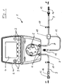
- Figure 1 shows a sketch of the structure of a liquor drainage system according to a preferred embodiment of the present invention.
- the embodiment of the CSF drainage system 1 shown in Fig. 1 comprises, according to the present invention, a main component 2 having a housing 2 in which an electronic control with electronic means for the calculations described above is housed. On the housing 2 input and control elements 3 are arranged, can be entered manually on the required for the operation of the CSF drainage system 1 operating parameters or a desired operating mode of the CSF drainage system. Via a display 4, all entered operating parameters and / or current operating measured values and operating modes of the CSF drainage system 1 can be displayed.
- the main component 2 of the CSF drainage system 1 further comprises a peristaltic pump 5 with connections 6 for hose connections 9 of a hose system.
- the tube connections 9 connected to the peristaltic pump 5 are on the one hand a cerebrospinal fluid supply line (brain catheter) 8 between the peristaltic pump 5 and the patient and on the other hand a hose connection 7 between the peristaltic pump 5 and a discharge bag (not shown) in which collects the pumped cerebrospinal fluid (cerebrospinal fluid).
- the connecting direction of the hose connection 7 to the drainage bag and indicated by the arrow B the connection direction of the hose connection 8 to the patient by the arrow A.
- the hose connections 9 of the hose system have an inner diameter of about 1.0 mm, an outer diameter of about 4.0 mm, a wall thickness of about 1.5 mm and a hardness in the range of 50-55 Shore Have a.
- the peristaltic pump 5 is constructed in a known manner and comprises a flexible circularly arranged pump tube segment.
- the axis of a pump rotor is mounted in the center of the circularly arranged pump tube segment, at the radially outer ends of which rotatably mounted rollers are provided. With the rotation of the pump rotor, the rollers roll on the circular pump tube segment, compressing the pump tube segment.
- a fluid located in the pump hose segment is conveyed in the direction of rotation of the pump rotor.
- Such a peristaltic pump has the advantage that the fluid contained in the tube does not come into contact with foreign bodies and thus contamination of the fluid is excluded.
- a pressure sensor 10 is arranged, which measures the pressure of the liquor in the CSF supply line 8 permanently or at intervals.
- the pressure readings determined by the pressure sensor are converted into electrical signals and forwarded via an electrical line 11 to the electrical control in the main component 2 of the liquor drainage system 1.
- the electrical line 11 is connected by the pressure sensor 10 via a connection 12 to the main component 2 of the liquor drainage system 1 via a corresponding interface (not shown).
- the electrical control of the CSF drainage system 1 uses the operating readings transmitted by the pressure sensor 10 from the pressure in the CSF supply line 8 as a basis for the calculations in the electrical control for controlled operation of the peristaltic pump 5. If, for example, a pressure in the Liquor supply line 8 is detected, which is above a predetermined operating parameter or outside a certain Pressure range is, the electrical control of the CSF drainage system 1, the peristaltic pump 5 can be activated.
- the electrical control can stop the operation of the peristaltic pump 5.
- the CSF drainage system 1 may include detection means which determine the volume of liquor delivered and use the drained liquor volume as the basis for the control of the pump 5. For this purpose, for example, the number of revolutions of the pump rotor can be used, since this is in direct proportion to the funded by the peristaltic pump 5 volume.
- Both the hose connection 7 between the hose pump 5 and the discharge bag and the liquor supply line 8 between the hose pump and the patient can be equipped with a branch, for example in the form of a 3-way valve 17, are connected via the other hose lines to the hose system can.
- the hose connections 9 are respectively connected via suitable hose connection elements 13, 14, 15, 16 to further hose segments or other components of the liquor drainage system 1 which carry liquor liquid.
- the hose connection elements or hose couplings 13, 14, 15, 16 are each designed so that they ensure a pressure-safe connection of the hose connections and thus a closed hose system.
- the hose connection elements or hose couplings 13, 14, 15, 16 may be designed so that they have a disposable use of the hose connections 7, 8 or of the entire Ensure tubing sets, ie that a hose connections 7, 8 can be used only once in the closed-circuit tube to ensure their sterility.
- at least one connecting element 13, 14, 15, 16 may be formed such that the pressure sensor 10 can be received or integrated therein. In this way, the pressure sensor would be placed in direct contact with the liquor in the drainage system and mounted easily replaceable.
- the liquor drainage system 1 is characterized on the one hand by simple operation and on the other hand ensures a controlled liquor drainage process, in which the drained liquor volume regulated as needed and the drainage pressure or the CSF pressure can be reliably maintained within a certain pressure range ,
Landscapes
- Health & Medical Sciences (AREA)
- Engineering & Computer Science (AREA)
- Heart & Thoracic Surgery (AREA)
- Biomedical Technology (AREA)
- Public Health (AREA)
- Hematology (AREA)
- Life Sciences & Earth Sciences (AREA)
- Animal Behavior & Ethology (AREA)
- General Health & Medical Sciences (AREA)
- Veterinary Medicine (AREA)
- Anesthesiology (AREA)
- Vascular Medicine (AREA)
- Ophthalmology & Optometry (AREA)
- Otolaryngology (AREA)
- Neurology (AREA)
- General Engineering & Computer Science (AREA)
- Mechanical Engineering (AREA)
- External Artificial Organs (AREA)
- Measuring And Recording Apparatus For Diagnosis (AREA)
- Quick-Acting Or Multi-Walled Pipe Joints (AREA)
- Separation Using Semi-Permeable Membranes (AREA)
Claims (20)
- Système de drainage du liquide céphalo-rachidien (1) destiné à drainer le liquide cérébro-spinal (liquide céphalo-rachidien), munid'une conduite d'arrivée (8) du liquide céphalo-rachidien et d'un capteur de pression (10), qui détermine la pression dans la conduite d'arrivée (8) du liquide céphalo-rachidien, etd'une pompe (5), qui évacue par pompage le liquide cérébro-spinal en fonction de paramètres de fonctionnement prédéterminés et de valeurs de fonctionnement mesurées, de moyens de détection qui déterminent le volume de liquide cérébro-spinal drainé,
caractérisé en ce que
le moyen de détection est conçu pour calculer le volume du liquide céphalo-rachidien drainé à partir de la rotation de la pompe et du diamètre de tuyau flexible, la pompe (5) est conçue pour évacuer par pompage le liquide cérébro-spinal en fonction du volume de liquide céphalo-rachidien drainé et en fonction de la pression mesurée dans la conduite d'arrivée (8) du liquide céphalo-rachidien. - Système selon la revendication 1, les paramètres de fonctionnement prédéterminés et les valeurs de fonctionnement mesurées comprenant au moins la pression mesurée dans la conduite d'arrivée (8) du liquide céphalo-rachidien ou le volume du liquide céphalo-rachidien évacué par pompage.
- Système selon l'une des revendications précédentes, la pompe (5) étant conçue comme pompe péristaltique.
- Système selon l'une des revendications précédentes, le capteur de pression (10) étant disposé sur la conduite d'arrivée (8) du liquide céphalo-rachidien, de préférence à proximité du patient.
- Système selon l'une des revendications précédentes, le capteur de pression (10) étant pourvu de moyens de fixation qui permettent un agencement du capteur de pression (10) dans la région de tête du patient, de préférence au niveau de l'oreille du patient.
- Système selon l'une des revendications précédentes, plusieurs capteurs de pression (10) étant prévus qui déterminent en commun ou en alternance la pression dans la conduite d'arrivée (8) du liquide céphalo-rachidien.
- Système selon l'une des revendications précédentes, le capteur de pression (10) étant conçu comme capteur de pression électronique, en particulier comme capteur de pression piézoélectrique, qui convertit en impulsions électriques les variations de pression dans la conduite d'arrivée (8) du liquide céphalo-rachidien.
- Système selon l'une des revendications précédentes, le système de drainage du liquide céphalo-rachidien (1) comprenant une commande électronique, qui effectue les calculs nécessaires au fonctionnement de la pompe (5) à partir des paramètres de fonctionnement prédéterminés et des valeurs de fonctionnement mesurées.
- Système selon la revendication 8, la commande électronique étant programmable, de sorte que certains déroulements opératoires, par exemple pour différentes applications médicales, sont réalisables.
- Système selon l'une des revendications 8 ou 9, la commande électronique comprenant des fonctions d'alarme, qui sont activées lorsqu'une valeur de fonctionnement mesurée s'écarte du paramètre de fonctionnement prédéterminé correspondant.
- Système selon l'une des revendications 8 à 10, la commande électronique comprenant au moins une interface, comme par exemple une liaison câblée, infrarouge ou radio ou une puce/carte à mémoire amovible, par l'intermédiaire de laquelle les valeurs de fonctionnement mesurées et/ou les paramètres de fonctionnement peuvent être transmis à un système externe de contrôle ou à un dispositif externe d'affichage.
- Système selon l'une des revendications 8 à 11, la commande électronique comprenant des moyens électroniques de mémorisation dans lesquels peuvent être mémorisés par exemple des déroulements opératoires prédéterminés du système de drainage du liquide céphalo-rachidien (1) ou une documentation temporelle du fonctionnement du système de drainage du liquide céphalo-rachidien (1).
- Système selon l'une des revendications précédentes, le système de drainage du liquide céphalo-rachidien (1) comportant des moyens d'entrée, par l'intermédiaire desquels des paramètres de fonctionnement, comme par exemple les valeurs limites prédéterminées de la pression du liquide céphalo-rachidien, peuvent être entrés dans la commande électronique.
- Système selon l'une des revendications précédentes, le système de drainage du liquide céphalo-rachidien (1) comportant des éléments de commande par l'intermédiaire desquels par exemple le fonctionnement de la pompe (5) peut être commandé directement ou une fonction d'alarme peut être activée manuellement.
- Système selon l'une des revendications précédentes, le système de drainage du liquide céphalo-rachidien (1) comportant un affichage optique par l'intermédiaire duquel des paramètres de fonctionnement réglés et/ou les valeurs de fonctionnement mesurées actuelles peuvent être affichés.
- Système selon l'une des revendications précédentes, le système de drainage du liquide céphalo-rachidien (1) étant équipé d'un réservoir pour l'énergie électrique et/ou d'un accumulateur pour l'alimentation électrique indépendante du secteur.
- Système selon l'une des revendications précédentes, le système de drainage du liquide céphalo-rachidien (1) comprenant un système fermé de tuyaux flexibles (9) comportant des liaisons à tuyaux flexibles (7, 8) afin de relier les composants conduisant le liquide.
- Système selon la revendication 17, le système fermé de tuyaux flexibles (9) comprenant des moyens, en particulier des éléments de raccordement (13, 14, 15, 16) qui garantissent la possibilité d'usage unique des liaisons à tuyaux flexibles (7, 8).
- Système selon la revendication 18, le capteur de pression (10) étant intégré dans un des éléments de liaison (13, 14, 15, 16).
- Système selon l'une des revendications précédentes, le système de drainage du liquide céphalo-rachidien (1) comprenant une poche d'évacuation destinée à recueillir le liquide céphalo-rachidien évacué.
Priority Applications (10)
| Application Number | Priority Date | Filing Date | Title |
|---|---|---|---|
| DE502005002730T DE502005002730D1 (de) | 2005-08-02 | 2005-08-02 | Liquor-Drainagesystem |
| EP05016789A EP1749549B1 (fr) | 2005-08-02 | 2005-08-02 | Système de drainage de fluide cephalo-rachidien |
| ES05016789T ES2303159T3 (es) | 2005-08-02 | 2005-08-02 | Sistema de drenaje de liquido cefalorraquideo. |
| AT05016789T ATE385194T1 (de) | 2005-08-02 | 2005-08-02 | Liquor-drainagesystem |
| AU2006275211A AU2006275211A1 (en) | 2005-08-02 | 2006-03-24 | Drainage system for cerebrospinal fluid |
| CA2612440A CA2612440C (fr) | 2005-08-02 | 2006-03-24 | Systeme de drainage de liquide cephalo-rachidien |
| PCT/EP2006/002730 WO2007014582A1 (fr) | 2005-08-02 | 2006-03-24 | Systeme de drainage de liquide cephalo-rachidien |
| JP2008524367A JP4851520B2 (ja) | 2005-08-02 | 2006-03-24 | 脳脊髄液用の排出システム |
| US11/818,893 US8608716B2 (en) | 2005-08-02 | 2007-06-15 | Drainage system for cerebrospinal fluid |
| US14/076,543 US9717890B2 (en) | 2005-08-02 | 2013-11-11 | Drainage system for cerebrospinal fluid |
Applications Claiming Priority (1)
| Application Number | Priority Date | Filing Date | Title |
|---|---|---|---|
| EP05016789A EP1749549B1 (fr) | 2005-08-02 | 2005-08-02 | Système de drainage de fluide cephalo-rachidien |
Publications (2)
| Publication Number | Publication Date |
|---|---|
| EP1749549A1 EP1749549A1 (fr) | 2007-02-07 |
| EP1749549B1 true EP1749549B1 (fr) | 2008-01-30 |
Family
ID=35406417
Family Applications (1)
| Application Number | Title | Priority Date | Filing Date |
|---|---|---|---|
| EP05016789A Active EP1749549B1 (fr) | 2005-08-02 | 2005-08-02 | Système de drainage de fluide cephalo-rachidien |
Country Status (9)
| Country | Link |
|---|---|
| US (2) | US8608716B2 (fr) |
| EP (1) | EP1749549B1 (fr) |
| JP (1) | JP4851520B2 (fr) |
| AT (1) | ATE385194T1 (fr) |
| AU (1) | AU2006275211A1 (fr) |
| CA (1) | CA2612440C (fr) |
| DE (1) | DE502005002730D1 (fr) |
| ES (1) | ES2303159T3 (fr) |
| WO (1) | WO2007014582A1 (fr) |
Families Citing this family (58)
| Publication number | Priority date | Publication date | Assignee | Title |
|---|---|---|---|---|
| IL152950A0 (en) | 2002-11-19 | 2003-06-24 | Biometrix Ltd | A fluid administrating manifold |
| US7585280B2 (en) | 2004-12-29 | 2009-09-08 | Codman & Shurtleff, Inc. | System and method for measuring the pressure of a fluid system within a patient |
| DE502005002730D1 (de) * | 2005-08-02 | 2008-03-20 | Moeller Medical Gmbh & Co Kg | Liquor-Drainagesystem |
| ATE456383T1 (de) | 2006-09-28 | 2010-02-15 | Tyco Healthcare | Tragbares wundtherapiesystem |
| MX2009008397A (es) * | 2007-02-09 | 2009-10-28 | Kci Licensing Inc | Sistema y metodo para administrar presion reducida en un sitio de tejido. |
| GB0712763D0 (en) | 2007-07-02 | 2007-08-08 | Smith & Nephew | Apparatus |
| GB0803564D0 (en) | 2008-02-27 | 2008-04-02 | Smith & Nephew | Fluid collection |
| US8414519B2 (en) | 2008-05-21 | 2013-04-09 | Covidien Lp | Wound therapy system with portable container apparatus |
| US8177763B2 (en) | 2008-09-05 | 2012-05-15 | Tyco Healthcare Group Lp | Canister membrane for wound therapy system |
| US10912869B2 (en) | 2008-05-21 | 2021-02-09 | Smith & Nephew, Inc. | Wound therapy system with related methods therefor |
| US8827983B2 (en) | 2008-08-21 | 2014-09-09 | Smith & Nephew, Inc. | Sensor with electrical contact protection for use in fluid collection canister and negative pressure wound therapy systems including same |
| US8679048B2 (en) | 2009-03-31 | 2014-03-25 | Likvor Ab | Optimization of hydrocephalus shunt settings |
| US9074920B2 (en) | 2009-06-03 | 2015-07-07 | Biometrix Ltd. | Apparatus and method for bedside collection of body fluids and automatic volume level monitoring |
| US9357950B2 (en) | 2009-06-03 | 2016-06-07 | Biometrix Ltd. | Apparatus and method of fluid aspiration |
| US8109899B2 (en) | 2009-07-06 | 2012-02-07 | Likvor Ab | Fully automated method of measuring and regulating cerebrospinal fluid parameters using disposable tube-set |
| ES2709486T3 (es) | 2010-03-19 | 2019-04-16 | Univ Washington | Sistemas de drenaje para exceso de fluidos corporales y métodos asociados |
| CA140189S (en) | 2010-10-15 | 2011-11-07 | Smith & Nephew | Medical dressing |
| CA140188S (en) | 2010-10-15 | 2011-11-07 | Smith & Nephew | Medical dressing |
| DE102012209405A1 (de) | 2012-06-04 | 2013-12-05 | Spiegelberg GmbH & Co. KG | Vorrichtung zur Drainage von Körperflüssigkeiten |
| USD764654S1 (en) | 2014-03-13 | 2016-08-23 | Smith & Nephew, Inc. | Canister for collecting wound exudate |
| US9084620B2 (en) | 2013-03-14 | 2015-07-21 | DePuy Synthes Products, Inc. | Detection and clearing of occlusions in catheters |
| US10463264B2 (en) | 2013-10-15 | 2019-11-05 | Aqueduct Critical Care, Inc. | Pressure/force sensors having a flexible membrane, dynamic and static pressure/force sensor calibration methods |
| JP6634661B2 (ja) * | 2014-01-07 | 2020-01-22 | ポトレロ メディカル,インコーポレイテッド | 体液の排液及び分析用のシステム、器具ならびに方法 |
| EP3094242A4 (fr) | 2014-01-16 | 2018-03-14 | University Of Washington Through Its Center For Commercialization | Ensembles de référence de pression pour systèmes de drainage de fluides corporels et procédés associés |
| CA2944007C (fr) * | 2014-04-07 | 2022-06-07 | Csfrefresh Incorporated | Shunt de mesure csf programmable |
| USD764048S1 (en) | 2014-05-28 | 2016-08-16 | Smith & Nephew, Inc. | Device for applying negative pressure to a wound |
| USD764047S1 (en) | 2014-05-28 | 2016-08-16 | Smith & Nephew, Inc. | Therapy unit assembly |
| USD764653S1 (en) | 2014-05-28 | 2016-08-23 | Smith & Nephew, Inc. | Canister for collecting wound exudate |
| USD770173S1 (en) | 2014-06-02 | 2016-11-01 | Smith & Nephew, Inc. | Bag |
| USD765830S1 (en) | 2014-06-02 | 2016-09-06 | Smith & Nephew, Inc. | Therapy unit assembly |
| CN106687154B (zh) | 2014-07-31 | 2021-02-09 | 史密夫和内修有限公司 | 用于施用减压治疗的系统和方法 |
| JP6754354B2 (ja) * | 2014-09-28 | 2020-09-16 | ポトレロ メディカル,インコーポレイテッド | 生理学的データを感知し、体液を排出しかつ分析するためのシステム、デバイス、および方法 |
| PL225073B1 (pl) * | 2014-10-24 | 2017-02-28 | Vimex Spółka Z Ograniczoną Odpowiedzialnością | Pompa perystaltyczna |
| JP6878307B2 (ja) | 2015-05-20 | 2021-05-26 | グラビタス メディカル,インコーポレイテッド | 胃内容物の残存量の決定装置 |
| CN105126186A (zh) * | 2015-10-21 | 2015-12-09 | 王学建 | 脑脊液体外引流系统的引流调节装置 |
| JP1586116S (fr) | 2016-02-29 | 2017-09-19 | ||
| SG10201602099QA (en) * | 2016-03-17 | 2017-10-30 | Changi General Hospital Pte Ltd | A body fluid drainage device |
| CO2016005747A1 (es) * | 2016-12-23 | 2018-07-10 | Univ Eia | Dispositivo y método para controlar el flujo de un líquido |
| CA3056201A1 (fr) * | 2017-03-17 | 2018-09-20 | Irras Ab | Systeme d'echange de fluide et procedes associes |
| EP3612242A1 (fr) | 2017-04-19 | 2020-02-26 | Smith & Nephew, Inc | Cartouches pour traitement de plaies par pression négative |
| CN107096078A (zh) * | 2017-05-12 | 2017-08-29 | 中国人民解放军第二军医大学第二附属医院 | 脑脊液引流装置 |
| CN107714188A (zh) * | 2017-09-26 | 2018-02-23 | 中国人民解放军总医院 | 一种手术用废液收集装置 |
| BR112020011994A2 (pt) * | 2017-12-15 | 2020-11-17 | The Board Of Regents, The University Of Texas System | sistemas e métodos para evacuar hematomas subdurais |
| JP2021519668A (ja) | 2018-03-22 | 2021-08-12 | クライオライフ、インコーポレイテッド | 中枢神経系局所的低体温装置および方法 |
| CN111803734A (zh) * | 2018-09-28 | 2020-10-23 | 德州飚丰信息技术有限公司 | 一种智能积液引流装置 |
| CN112121244A (zh) * | 2018-09-28 | 2020-12-25 | 德州飚丰信息技术有限公司 | 医疗用智能引流控制装置 |
| KR102201288B1 (ko) * | 2019-04-01 | 2021-01-11 | 국립암센터 | 뇌질환치료 시스템 |
| CN111558125B (zh) * | 2019-04-15 | 2022-03-11 | 华中科技大学同济医学院附属协和医院 | 一种智能颅内脑脊液引流装置 |
| CN110115779A (zh) * | 2019-05-20 | 2019-08-13 | 刘云峰 | 一种胸腹腔液体负压泵吸装置 |
| CN110432974A (zh) * | 2019-07-04 | 2019-11-12 | 中国人民解放军总医院 | 一种手术用废液收集装置 |
| US11103683B1 (en) | 2020-02-10 | 2021-08-31 | Frederick H. Sklar | Implantable intracranial pulse pressure modulator and system and method for use of same |
| CN116367873A (zh) | 2020-09-03 | 2023-06-30 | 大脑空间公司 | 用于患者护理的体液管理系统 |
| US20230123678A1 (en) * | 2021-10-15 | 2023-04-20 | Wisconsin Alumni Research Foundation | Automatic In Vitro Diagnostic Medical Device for Intraventricular Drainage |
| CN113975480B (zh) * | 2021-10-29 | 2024-05-24 | 首都医科大学宣武医院 | 一种引流控制方法和装置 |
| US12090093B2 (en) | 2022-11-07 | 2024-09-17 | Frederick H. Sklar | Surgical universal headrest including skull pin holder assembly |
| US20240151347A1 (en) | 2022-11-07 | 2024-05-09 | Frederick H. Sklar | Base station assembly for an operating room table |
| US12082981B2 (en) | 2022-11-07 | 2024-09-10 | Frederick H. Sklar | Surgical armrest |
| CN115998388B (zh) * | 2023-02-27 | 2024-03-19 | 迈德微创(天津)医疗器械有限责任公司 | 一种腰穿用脑脊液测压装置及方法 |
Family Cites Families (34)
| Publication number | Priority date | Publication date | Assignee | Title |
|---|---|---|---|---|
| DE3127882A1 (de) | 1981-07-15 | 1983-02-03 | Jean Richard Dr. 3000 Hannover Moringlane | Mess- und ableitungsvorrichtung zum studium sowie zur behandlung des hydrocephalus und zum monitoring bei externer liquordrainage |
| JPS60220074A (ja) * | 1984-04-14 | 1985-11-02 | 株式会社豊田中央研究所 | モニタ付ドレナ−ジチユ−ブ |
| US4902277A (en) | 1987-08-26 | 1990-02-20 | Orthoconcept | Circulating a liquid through a joint |
| US5000733A (en) | 1986-05-23 | 1991-03-19 | Orthoconcept S.A. | Circulating a liquid through a joint |
| EP0323535A1 (fr) * | 1988-01-05 | 1989-07-12 | Hellige GmbH | Armature déstinée à l'implantation de biocapteurs dans la voûte crânienne |
| US4904237A (en) * | 1988-05-16 | 1990-02-27 | Janese Woodrow W | Apparatus for the exchange of cerebrospinal fluid and a method of treating brain and spinal cord injuries |
| DE69004682T2 (de) | 1990-03-28 | 1994-04-28 | Fms Sa | Montagevorrichtung eines Schlauches in einer peristaltischen Pumpe. |
| US5195536A (en) * | 1991-09-12 | 1993-03-23 | Axon Medical, Inc. | Self-adhering noninvasive intracorporeal movement detector |
| JPH05300941A (ja) * | 1992-04-28 | 1993-11-16 | Japan Medical Dynamic Marketing Inc | 脳室シャントにおけるシャントバルブの流量のチェック方法 |
| EP0617913B1 (fr) | 1993-03-26 | 2001-11-21 | Edwards Lifesciences Corporation | Moniteur de pression intracranienne et cathéter de drainage |
| US5492455A (en) * | 1994-06-23 | 1996-02-20 | Lancer Corporation | Pumping apparatus including a quick connect interface |
| DE69526613T2 (de) * | 1994-07-12 | 2002-08-29 | Medrad, Inc. | Informationswegregelkreis für ein System, das medizinische Flüssigkeiten ausliefert |
| US5683357A (en) * | 1995-12-01 | 1997-11-04 | Magram; Gary | External cerebrospinal fluid drain apparatus |
| US6689085B1 (en) * | 1996-07-11 | 2004-02-10 | Eunoe, Inc. | Method and apparatus for treating adult-onset dementia of the Alzheimer's type |
| US5980480A (en) | 1996-07-11 | 1999-11-09 | Cs Fluids, Inc. | Method and apparatus for treating adult-onset dementia of the alzheimer's type |
| US20030004495A1 (en) * | 1996-07-11 | 2003-01-02 | Eunoe, Inc. | Apparatus and methods for volumetric CSF removal |
| DE29621904U1 (de) | 1996-12-17 | 1997-01-30 | DISPOMEDICA GMBH, 22041 Hamburg | Stativ zum Einsatz in der Medizin |
| US6248080B1 (en) * | 1997-09-03 | 2001-06-19 | Medtronic, Inc. | Intracranial monitoring and therapy delivery control device, system and method |
| FR2772278B1 (fr) * | 1997-12-17 | 2000-09-22 | Nmt Neurosciences Implants | Dispositif de drainage externe de fluide biologique |
| EP0982048A1 (fr) * | 1998-03-12 | 2000-03-01 | Leonhardt, Steffen, Dr.-Ing. | Implant de drainage à commande de fluide cephalo-rachidien |
| US6105582A (en) * | 1998-07-28 | 2000-08-22 | Pranevicius; Osvaldas | Cerebral blood outflow maintenance during intracranial hypertension |
| US6533733B1 (en) * | 1999-09-24 | 2003-03-18 | Ut-Battelle, Llc | Implantable device for in-vivo intracranial and cerebrospinal fluid pressure monitoring |
| US7933780B2 (en) * | 1999-10-22 | 2011-04-26 | Telaric, Llc | Method and apparatus for controlling an infusion pump or the like |
| JP3175742B1 (ja) | 1999-10-22 | 2001-06-11 | ライオン株式会社 | コンタクトレンズ用眼科用組成物 |
| JP2004513681A (ja) * | 2000-07-21 | 2004-05-13 | メドトロニック,インコーポレイテッド | 生体パラメータを測定しかつ通信する装置及び方法 |
| KR100380180B1 (ko) | 2000-09-05 | 2003-04-14 | 한국과학기술연구원 | 매립지 차수막의 파손위치 검지용 감지기 |
| JP2003016357A (ja) | 2001-06-28 | 2003-01-17 | Ntt Docomo Inc | 情報提供方法、情報提供装置、情報提供システム、情報提供サービスの収益分配方法、その収益分配装置、その収益分配システムおよびコンピュータ・プログラム |
| DE10233053B4 (de) | 2002-07-19 | 2005-02-24 | W.O.M. World Of Medicine Ag | Vorrichtung zum Durchspülen einer Körperhöhle |
| DE10317308B4 (de) | 2003-04-14 | 2005-09-08 | Smiths Medical Deutschland Gmbh | Liquor-Drainageanordnung |
| US20050055009A1 (en) * | 2003-09-05 | 2005-03-10 | Codman & Shurtleff, Inc. | Method and apparatus for managing normal pressure hydrocephalus |
| JP2005300941A (ja) | 2004-04-13 | 2005-10-27 | Konica Minolta Opto Inc | 撮像装置 |
| EP1781366B1 (fr) * | 2004-07-20 | 2015-04-22 | Medtronic, Inc. | Dispositif de drainage de fluide spinal cerebral implantable |
| FR2879621B1 (fr) | 2004-12-16 | 2007-04-06 | Total France Sa | Huile pour moteur marin 4-temps |
| DE502005002730D1 (de) * | 2005-08-02 | 2008-03-20 | Moeller Medical Gmbh & Co Kg | Liquor-Drainagesystem |
-
2005
- 2005-08-02 DE DE502005002730T patent/DE502005002730D1/de active Active
- 2005-08-02 EP EP05016789A patent/EP1749549B1/fr active Active
- 2005-08-02 AT AT05016789T patent/ATE385194T1/de active
- 2005-08-02 ES ES05016789T patent/ES2303159T3/es active Active
-
2006
- 2006-03-24 AU AU2006275211A patent/AU2006275211A1/en not_active Abandoned
- 2006-03-24 JP JP2008524367A patent/JP4851520B2/ja active Active
- 2006-03-24 WO PCT/EP2006/002730 patent/WO2007014582A1/fr active Application Filing
- 2006-03-24 CA CA2612440A patent/CA2612440C/fr active Active
-
2007
- 2007-06-15 US US11/818,893 patent/US8608716B2/en active Active
-
2013
- 2013-11-11 US US14/076,543 patent/US9717890B2/en active Active
Also Published As
| Publication number | Publication date |
|---|---|
| ES2303159T3 (es) | 2008-08-01 |
| ATE385194T1 (de) | 2008-02-15 |
| US20140066903A1 (en) | 2014-03-06 |
| US9717890B2 (en) | 2017-08-01 |
| WO2007014582A1 (fr) | 2007-02-08 |
| CA2612440A1 (fr) | 2007-02-08 |
| EP1749549A1 (fr) | 2007-02-07 |
| US8608716B2 (en) | 2013-12-17 |
| JP2009502374A (ja) | 2009-01-29 |
| JP4851520B2 (ja) | 2012-01-11 |
| AU2006275211A1 (en) | 2007-02-08 |
| US20080033400A1 (en) | 2008-02-07 |
| DE502005002730D1 (de) | 2008-03-20 |
| CA2612440C (fr) | 2013-11-26 |
Similar Documents
| Publication | Publication Date | Title |
|---|---|---|
| EP1749549B1 (fr) | Système de drainage de fluide cephalo-rachidien | |
| DE112009004377B4 (de) | Blutdruckmesseinrichtung, welche eine Manschette beinhaltet, welche um den Messort zu wickeln ist | |
| EP3060805B1 (fr) | Procédé de fonctionnement d'un dispositif d'alimentation qui sollicite un chanal avec un liquide, dispositif d'alimentation, catheter creux et pompe a catheter | |
| EP3141272B1 (fr) | Dispositif de surveillance d'un dispositif de traitement extracorporel du sang et dispositif de traitement extracorporel du sang | |
| DE69230837T2 (de) | Flüssigkeitsbehandlungssystem | |
| DE69315450T2 (de) | Zustandbestimmung einer Flüssigkeitsschlauchleitung | |
| EP2445545B1 (fr) | Dispositif de circulation du sang dans un circuit extracorporel | |
| EP2411070A1 (fr) | Dispositif de traitement de sang | |
| DE112010004179T5 (de) | Elektronisches Blutdruckmessgeät | |
| DE102014214359A1 (de) | Pumpenvorrichtung | |
| EP1960017B1 (fr) | Procédé de purge d'un filtre hydrophobe mouillé et dispositif de réalisation du procédé | |
| EP3108809A1 (fr) | Dispositif et procede de mesure de pression dans le c ur d'un patient | |
| DE102011102872B4 (de) | Blutbehandlungsvorrichtung | |
| DE10033192B4 (de) | Verfahren zur Detektion arterieller Einlaufprobleme während einer extrakorporalen Blutbehandlung und extrakorporale Blutbehandlungsvorrichtung | |
| DE202005012136U1 (de) | Liquor-Drainagesystem | |
| DE102015104786B4 (de) | Überwachung einer Infusionspumpe | |
| DE102017124927A1 (de) | System zur Vakuum-unterstützten venösen Drainage (VAVD) | |
| EP3765119B1 (fr) | Dispositif de surveillance d'un accès vasculaire en cours d'un traitement extracorporel du sang | |
| EP3520839A1 (fr) | Dispositif de surveillance et procédé de surveillance d'un dispositif de traitement extracorporel du sang | |
| DE3633080A1 (de) | Vorrichtung zur ueberwachung eines fluessigkeitsvolumens | |
| DE10305036A1 (de) | Drucksensor für eine medizinische Schlauchpumpe | |
| DE102004010843A1 (de) | Adapter und Pumpeninterface zur Druckmessung für eine Infusionspumpe | |
| DE2949654A1 (de) | Einrichtung zur verhinderung des eindringens von jfluessigkeit in das vakuumpumpenaggregat einer fluessigkeitspumpvorrichtung | |
| EP3501560A1 (fr) | Procédé de fonctionnement d'un système de traitement par sous-pression | |
| DE102017202795A1 (de) | Drainagevorrichtung |
Legal Events
| Date | Code | Title | Description |
|---|---|---|---|
| PUAI | Public reference made under article 153(3) epc to a published international application that has entered the european phase |
Free format text: ORIGINAL CODE: 0009012 |
|
| 17P | Request for examination filed |
Effective date: 20060531 |
|
| AK | Designated contracting states |
Kind code of ref document: A1 Designated state(s): AT BE BG CH CY CZ DE DK EE ES FI FR GB GR HU IE IS IT LI LT LU LV MC NL PL PT RO SE SI SK TR |
|
| AX | Request for extension of the european patent |
Extension state: AL BA HR MK YU |
|
| 17Q | First examination report despatched |
Effective date: 20060814 |
|
| RIN1 | Information on inventor provided before grant (corrected) |
Inventor name: HOELPER, BERND M. Inventor name: SCHROETER, WERNER Inventor name: TRAXLER, CHRISTOPH Inventor name: HOELPER, MANFRED Inventor name: MARTENS, DANIELA |
|
| 17Q | First examination report despatched |
Effective date: 20060814 |
|
| GRAP | Despatch of communication of intention to grant a patent |
Free format text: ORIGINAL CODE: EPIDOSNIGR1 |
|
| AKX | Designation fees paid |
Designated state(s): AT BE BG CH CY CZ DE DK EE ES FI FR GB GR HU IE IS IT LI LT LU LV MC NL PL PT RO SE SI SK TR |
|
| RIN1 | Information on inventor provided before grant (corrected) |
Inventor name: HOELPER, BERND M. Inventor name: SCHROETER, WERNER Inventor name: MARTENS, DANIELA Inventor name: TRAXLER, CHRISTOPH Inventor name: HOELPER, MANFRED |
|
| GRAS | Grant fee paid |
Free format text: ORIGINAL CODE: EPIDOSNIGR3 |
|
| GRAA | (expected) grant |
Free format text: ORIGINAL CODE: 0009210 |
|
| AK | Designated contracting states |
Kind code of ref document: B1 Designated state(s): AT BE BG CH CY CZ DE DK EE ES FI FR GB GR HU IE IS IT LI LT LU LV MC NL PL PT RO SE SI SK TR |
|
| REG | Reference to a national code |
Ref country code: GB Ref legal event code: FG4D Free format text: NOT ENGLISH |
|
| REG | Reference to a national code |
Ref country code: CH Ref legal event code: EP |
|
| REG | Reference to a national code |
Ref country code: IE Ref legal event code: FG4D Free format text: LANGUAGE OF EP DOCUMENT: GERMAN |
|
| REF | Corresponds to: |
Ref document number: 502005002730 Country of ref document: DE Date of ref document: 20080320 Kind code of ref document: P |
|
| GBT | Gb: translation of ep patent filed (gb section 77(6)(a)/1977) |
Effective date: 20080429 |
|
| PG25 | Lapsed in a contracting state [announced via postgrant information from national office to epo] |
Ref country code: IS Free format text: LAPSE BECAUSE OF FAILURE TO SUBMIT A TRANSLATION OF THE DESCRIPTION OR TO PAY THE FEE WITHIN THE PRESCRIBED TIME-LIMIT Effective date: 20080530 Ref country code: FI Free format text: LAPSE BECAUSE OF FAILURE TO SUBMIT A TRANSLATION OF THE DESCRIPTION OR TO PAY THE FEE WITHIN THE PRESCRIBED TIME-LIMIT Effective date: 20080130 |
|
| NLV1 | Nl: lapsed or annulled due to failure to fulfill the requirements of art. 29p and 29m of the patents act | ||
| REG | Reference to a national code |
Ref country code: ES Ref legal event code: FG2A Ref document number: 2303159 Country of ref document: ES Kind code of ref document: T3 |
|
| ET | Fr: translation filed | ||
| PG25 | Lapsed in a contracting state [announced via postgrant information from national office to epo] |
Ref country code: PT Free format text: LAPSE BECAUSE OF FAILURE TO SUBMIT A TRANSLATION OF THE DESCRIPTION OR TO PAY THE FEE WITHIN THE PRESCRIBED TIME-LIMIT Effective date: 20080630 Ref country code: LV Free format text: LAPSE BECAUSE OF FAILURE TO SUBMIT A TRANSLATION OF THE DESCRIPTION OR TO PAY THE FEE WITHIN THE PRESCRIBED TIME-LIMIT Effective date: 20080130 Ref country code: SI Free format text: LAPSE BECAUSE OF FAILURE TO SUBMIT A TRANSLATION OF THE DESCRIPTION OR TO PAY THE FEE WITHIN THE PRESCRIBED TIME-LIMIT Effective date: 20080130 Ref country code: PL Free format text: LAPSE BECAUSE OF FAILURE TO SUBMIT A TRANSLATION OF THE DESCRIPTION OR TO PAY THE FEE WITHIN THE PRESCRIBED TIME-LIMIT Effective date: 20080130 |
|
| REG | Reference to a national code |
Ref country code: IE Ref legal event code: FD4D |
|
| PG25 | Lapsed in a contracting state [announced via postgrant information from national office to epo] |
Ref country code: NL Free format text: LAPSE BECAUSE OF FAILURE TO SUBMIT A TRANSLATION OF THE DESCRIPTION OR TO PAY THE FEE WITHIN THE PRESCRIBED TIME-LIMIT Effective date: 20080130 Ref country code: SE Free format text: LAPSE BECAUSE OF FAILURE TO SUBMIT A TRANSLATION OF THE DESCRIPTION OR TO PAY THE FEE WITHIN THE PRESCRIBED TIME-LIMIT Effective date: 20080430 Ref country code: SK Free format text: LAPSE BECAUSE OF FAILURE TO SUBMIT A TRANSLATION OF THE DESCRIPTION OR TO PAY THE FEE WITHIN THE PRESCRIBED TIME-LIMIT Effective date: 20080130 Ref country code: DK Free format text: LAPSE BECAUSE OF FAILURE TO SUBMIT A TRANSLATION OF THE DESCRIPTION OR TO PAY THE FEE WITHIN THE PRESCRIBED TIME-LIMIT Effective date: 20080130 Ref country code: CZ Free format text: LAPSE BECAUSE OF FAILURE TO SUBMIT A TRANSLATION OF THE DESCRIPTION OR TO PAY THE FEE WITHIN THE PRESCRIBED TIME-LIMIT Effective date: 20080130 Ref country code: IE Free format text: LAPSE BECAUSE OF FAILURE TO SUBMIT A TRANSLATION OF THE DESCRIPTION OR TO PAY THE FEE WITHIN THE PRESCRIBED TIME-LIMIT Effective date: 20080130 |
|
| REG | Reference to a national code |
Ref country code: CH Ref legal event code: NV Representative=s name: PATENTANWALTSKANZLEI NUECKEL |
|
| PG25 | Lapsed in a contracting state [announced via postgrant information from national office to epo] |
Ref country code: RO Free format text: LAPSE BECAUSE OF FAILURE TO SUBMIT A TRANSLATION OF THE DESCRIPTION OR TO PAY THE FEE WITHIN THE PRESCRIBED TIME-LIMIT Effective date: 20080130 |
|
| PLBE | No opposition filed within time limit |
Free format text: ORIGINAL CODE: 0009261 |
|
| STAA | Information on the status of an ep patent application or granted ep patent |
Free format text: STATUS: NO OPPOSITION FILED WITHIN TIME LIMIT |
|
| 26N | No opposition filed |
Effective date: 20081031 |
|
| PG25 | Lapsed in a contracting state [announced via postgrant information from national office to epo] |
Ref country code: LT Free format text: LAPSE BECAUSE OF FAILURE TO SUBMIT A TRANSLATION OF THE DESCRIPTION OR TO PAY THE FEE WITHIN THE PRESCRIBED TIME-LIMIT Effective date: 20080130 |
|
| PG25 | Lapsed in a contracting state [announced via postgrant information from national office to epo] |
Ref country code: MC Free format text: LAPSE BECAUSE OF NON-PAYMENT OF DUE FEES Effective date: 20080831 |
|
| PG25 | Lapsed in a contracting state [announced via postgrant information from national office to epo] |
Ref country code: EE Free format text: LAPSE BECAUSE OF FAILURE TO SUBMIT A TRANSLATION OF THE DESCRIPTION OR TO PAY THE FEE WITHIN THE PRESCRIBED TIME-LIMIT Effective date: 20080130 Ref country code: BG Free format text: LAPSE BECAUSE OF FAILURE TO SUBMIT A TRANSLATION OF THE DESCRIPTION OR TO PAY THE FEE WITHIN THE PRESCRIBED TIME-LIMIT Effective date: 20080430 |
|
| PG25 | Lapsed in a contracting state [announced via postgrant information from national office to epo] |
Ref country code: CY Free format text: LAPSE BECAUSE OF FAILURE TO SUBMIT A TRANSLATION OF THE DESCRIPTION OR TO PAY THE FEE WITHIN THE PRESCRIBED TIME-LIMIT Effective date: 20080130 Ref country code: BE Free format text: LAPSE BECAUSE OF NON-PAYMENT OF DUE FEES Effective date: 20080831 |
|
| PG25 | Lapsed in a contracting state [announced via postgrant information from national office to epo] |
Ref country code: HU Free format text: LAPSE BECAUSE OF FAILURE TO SUBMIT A TRANSLATION OF THE DESCRIPTION OR TO PAY THE FEE WITHIN THE PRESCRIBED TIME-LIMIT Effective date: 20080731 Ref country code: LU Free format text: LAPSE BECAUSE OF NON-PAYMENT OF DUE FEES Effective date: 20080802 |
|
| PG25 | Lapsed in a contracting state [announced via postgrant information from national office to epo] |
Ref country code: GR Free format text: LAPSE BECAUSE OF FAILURE TO SUBMIT A TRANSLATION OF THE DESCRIPTION OR TO PAY THE FEE WITHIN THE PRESCRIBED TIME-LIMIT Effective date: 20080501 |
|
| PGFP | Annual fee paid to national office [announced via postgrant information from national office to epo] |
Ref country code: CH Payment date: 20130826 Year of fee payment: 9 Ref country code: AT Payment date: 20130821 Year of fee payment: 9 |
|
| PGFP | Annual fee paid to national office [announced via postgrant information from national office to epo] |
Ref country code: FR Payment date: 20130820 Year of fee payment: 9 |
|
| REG | Reference to a national code |
Ref country code: CH Ref legal event code: PL |
|
| REG | Reference to a national code |
Ref country code: AT Ref legal event code: MM01 Ref document number: 385194 Country of ref document: AT Kind code of ref document: T Effective date: 20140802 |
|
| PG25 | Lapsed in a contracting state [announced via postgrant information from national office to epo] |
Ref country code: CH Free format text: LAPSE BECAUSE OF NON-PAYMENT OF DUE FEES Effective date: 20140831 Ref country code: LI Free format text: LAPSE BECAUSE OF NON-PAYMENT OF DUE FEES Effective date: 20140831 |
|
| PG25 | Lapsed in a contracting state [announced via postgrant information from national office to epo] |
Ref country code: AT Free format text: LAPSE BECAUSE OF NON-PAYMENT OF DUE FEES Effective date: 20140802 |
|
| REG | Reference to a national code |
Ref country code: FR Ref legal event code: ST Effective date: 20150430 |
|
| PG25 | Lapsed in a contracting state [announced via postgrant information from national office to epo] |
Ref country code: FR Free format text: LAPSE BECAUSE OF NON-PAYMENT OF DUE FEES Effective date: 20140901 |
|
| P01 | Opt-out of the competence of the unified patent court (upc) registered |
Effective date: 20230526 |
|
| PGFP | Annual fee paid to national office [announced via postgrant information from national office to epo] |
Ref country code: TR Payment date: 20230829 Year of fee payment: 19 Ref country code: IT Payment date: 20230823 Year of fee payment: 19 Ref country code: GB Payment date: 20230822 Year of fee payment: 19 Ref country code: ES Payment date: 20230918 Year of fee payment: 19 |
|
| PGFP | Annual fee paid to national office [announced via postgrant information from national office to epo] |
Ref country code: DE Payment date: 20240531 Year of fee payment: 20 |