EP1746819B1 - Imaging device, image display method, and user interface - Google Patents
Imaging device, image display method, and user interface Download PDFInfo
- Publication number
- EP1746819B1 EP1746819B1 EP05738836A EP05738836A EP1746819B1 EP 1746819 B1 EP1746819 B1 EP 1746819B1 EP 05738836 A EP05738836 A EP 05738836A EP 05738836 A EP05738836 A EP 05738836A EP 1746819 B1 EP1746819 B1 EP 1746819B1
- Authority
- EP
- European Patent Office
- Prior art keywords
- image signal
- mode
- image
- displayed
- reproducing
- Prior art date
- Legal status (The legal status is an assumption and is not a legal conclusion. Google has not performed a legal analysis and makes no representation as to the accuracy of the status listed.)
- Expired - Fee Related
Links
- 238000003384 imaging method Methods 0.000 title claims abstract description 42
- 238000000034 method Methods 0.000 title claims description 14
- 230000007704 transition Effects 0.000 claims description 65
- 238000003825 pressing Methods 0.000 claims 1
- 238000010586 diagram Methods 0.000 description 13
- 238000001454 recorded image Methods 0.000 description 7
- 230000008569 process Effects 0.000 description 4
- 102100036848 C-C motif chemokine 20 Human genes 0.000 description 3
- 101000713099 Homo sapiens C-C motif chemokine 20 Proteins 0.000 description 3
- 238000012217 deletion Methods 0.000 description 3
- 230000037430 deletion Effects 0.000 description 3
- 101000911772 Homo sapiens Hsc70-interacting protein Proteins 0.000 description 2
- 101001139126 Homo sapiens Krueppel-like factor 6 Proteins 0.000 description 2
- 230000008859 change Effects 0.000 description 2
- 239000004973 liquid crystal related substance Substances 0.000 description 2
- 101000710013 Homo sapiens Reversion-inducing cysteine-rich protein with Kazal motifs Proteins 0.000 description 1
- 101000661807 Homo sapiens Suppressor of tumorigenicity 14 protein Proteins 0.000 description 1
- 230000005540 biological transmission Effects 0.000 description 1
- 230000003247 decreasing effect Effects 0.000 description 1
- 238000012840 feeding operation Methods 0.000 description 1
- 230000007246 mechanism Effects 0.000 description 1
- 238000012986 modification Methods 0.000 description 1
- 230000004048 modification Effects 0.000 description 1
- 230000003287 optical effect Effects 0.000 description 1
- GGCZERPQGJTIQP-UHFFFAOYSA-N sodium;9,10-dioxoanthracene-2-sulfonic acid Chemical compound [Na+].C1=CC=C2C(=O)C3=CC(S(=O)(=O)O)=CC=C3C(=O)C2=C1 GGCZERPQGJTIQP-UHFFFAOYSA-N 0.000 description 1
- 210000003813 thumb Anatomy 0.000 description 1
Images


Classifications
-
- H—ELECTRICITY
- H04—ELECTRIC COMMUNICATION TECHNIQUE
- H04N—PICTORIAL COMMUNICATION, e.g. TELEVISION
- H04N23/00—Cameras or camera modules comprising electronic image sensors; Control thereof
- H04N23/60—Control of cameras or camera modules
- H04N23/63—Control of cameras or camera modules by using electronic viewfinders
- H04N23/631—Graphical user interfaces [GUI] specially adapted for controlling image capture or setting capture parameters
-
- G—PHYSICS
- G06—COMPUTING; CALCULATING OR COUNTING
- G06F—ELECTRIC DIGITAL DATA PROCESSING
- G06F3/00—Input arrangements for transferring data to be processed into a form capable of being handled by the computer; Output arrangements for transferring data from processing unit to output unit, e.g. interface arrangements
- G06F3/01—Input arrangements or combined input and output arrangements for interaction between user and computer
- G06F3/03—Arrangements for converting the position or the displacement of a member into a coded form
- G06F3/041—Digitisers, e.g. for touch screens or touch pads, characterised by the transducing means
- G06F3/0412—Digitisers structurally integrated in a display
-
- G—PHYSICS
- G06—COMPUTING; CALCULATING OR COUNTING
- G06F—ELECTRIC DIGITAL DATA PROCESSING
- G06F3/00—Input arrangements for transferring data to be processed into a form capable of being handled by the computer; Output arrangements for transferring data from processing unit to output unit, e.g. interface arrangements
- G06F3/01—Input arrangements or combined input and output arrangements for interaction between user and computer
- G06F3/048—Interaction techniques based on graphical user interfaces [GUI]
- G06F3/0484—Interaction techniques based on graphical user interfaces [GUI] for the control of specific functions or operations, e.g. selecting or manipulating an object, an image or a displayed text element, setting a parameter value or selecting a range
- G06F3/0485—Scrolling or panning
-
- G—PHYSICS
- G06—COMPUTING; CALCULATING OR COUNTING
- G06F—ELECTRIC DIGITAL DATA PROCESSING
- G06F3/00—Input arrangements for transferring data to be processed into a form capable of being handled by the computer; Output arrangements for transferring data from processing unit to output unit, e.g. interface arrangements
- G06F3/01—Input arrangements or combined input and output arrangements for interaction between user and computer
- G06F3/048—Interaction techniques based on graphical user interfaces [GUI]
- G06F3/0487—Interaction techniques based on graphical user interfaces [GUI] using specific features provided by the input device, e.g. functions controlled by the rotation of a mouse with dual sensing arrangements, or of the nature of the input device, e.g. tap gestures based on pressure sensed by a digitiser
- G06F3/0488—Interaction techniques based on graphical user interfaces [GUI] using specific features provided by the input device, e.g. functions controlled by the rotation of a mouse with dual sensing arrangements, or of the nature of the input device, e.g. tap gestures based on pressure sensed by a digitiser using a touch-screen or digitiser, e.g. input of commands through traced gestures
-
- H—ELECTRICITY
- H04—ELECTRIC COMMUNICATION TECHNIQUE
- H04N—PICTORIAL COMMUNICATION, e.g. TELEVISION
- H04N23/00—Cameras or camera modules comprising electronic image sensors; Control thereof
-
- H—ELECTRICITY
- H04—ELECTRIC COMMUNICATION TECHNIQUE
- H04N—PICTORIAL COMMUNICATION, e.g. TELEVISION
- H04N23/00—Cameras or camera modules comprising electronic image sensors; Control thereof
- H04N23/60—Control of cameras or camera modules
- H04N23/63—Control of cameras or camera modules by using electronic viewfinders
- H04N23/633—Control of cameras or camera modules by using electronic viewfinders for displaying additional information relating to control or operation of the camera
Definitions
- the present invention relates to an imaging apparatus, a screen displaying method, and a user interface that allow transitions between a shooting mode and a reproducing mode to smoothly take place.
- Digital cameras that have a displaying device for example an LCD (Liquid Crystal Display) with a relatively large screen have been widespread.
- the LCD is used to set a composition, an angle of view, and so forth.
- the LCD is used to display the reproduced image.
- An electronic camera that can shoot moving images and still images and that can display them in the order of days, months, and years of which they were shot along a time axis is described in the specification of Japanese Patent No. 3403324 .
- the digital camera described in the document displays captured images so that they can be easily searched for an image to be reproduced.
- the conventional digital camera needed an operation of an input device to switch a mode between a shooting mode and a reproducing mode.
- the shooting mode and the reproducing mode were separated, for example it was difficult for the user to shoot an image while checking an image that has been just captured.
- a user interface of a digital camera be predictable and intuitional by a plurality of users. It can be said that such an interface has an affinity with a user's conceptual model.
- the electronic camera described in the specification of Japanese Patent No. 3403324 deals with only images that were captured. Thus, the specification does not mention an image captured in the shooting mode. The specification does not mention that modes are switched having an affinity with the user's conceptual model.
- an object of the present invention is to provide an imaging apparatus, a screen displaying method, and a user interface that allow a shooting mode and a reproducing mode to be switched having an affinity with a seamless conceptual model and thereby their operability to be improved.
- Another object of the present invention is to provide an imaging apparatus, a screen displaying method, and a user interface that allow a shooting mode and a reproducing mode to co-exist and thereby their operability to be improved.
- a first aspect of the present invention is an imaging apparatus, comprising: an imaging unit; a display; a storage which temporarily stores an image signal which is output from the imaging unit and an image signal which is output to the display; an input unit which accepts an operation input of a user; and a control unit which controls writing and reading of the storage, wherein the control unit controls the storage so that a first image signal as an image signal of an object which the imaging unit is currently capturing and a second image signal which has been already captured are successively displayed along a time axis on the display, and wherein the control unit controls the storage so that transitions from one of a shooting mode in which the first image signal is displayed on the display and a reproducing mode in which only the second image signal is displayed on the display to the other seamlessly take place according to an operation input from the input unit.
- a second aspect of the present invention is a screen displaying method of displaying image signals for an imaging apparatus having a display, the method comprising the steps of: displaying a first image signal which is an image signal of an object which an imaging unit is currently capturing on the display when a shooting mode takes place; displaying only a second image signal which has been already captured on the display when a reproducing mode takes place; and causing transitions from one mode of the shooting mode and the reproducing mode to the other mode to seamlessly take place according to an operation input.
- a third aspect of the present invention is a user interface for an imaging apparatus, comprising: a display; an input unit which is operable in at least two directions; a shooting mode in which a first image signal as an image of an object which an imaging unit is currently capturing is displayed on the display; and a reproducing mode in which only a second image signal which has been already captured is displayed on the display, wherein transitions from one mode of the shooting mode and the reproducing mode to the other mode seamlessly take place according to the directions of the operation of the input unit.
- a fourth aspect of the present invention is an imaging apparatus, comprising: an imaging unit; a display; a storage which temporarily stores an image signal which is output from the imaging unit and an image signal which is output to the display; an input unit which accepts an operation input of a user; and a control unit which controls writing and reading of the storage, wherein the control unit controls the storage so that a first image signal as an image signal of an object which the imaging unit is currently capturing and a second image signal which has been already captured are displayed at the same time, but the first image signal and the second image signal do not overlap.
- a fifth aspect of the present invention is an image signal displaying method for an imaging apparatus having a display, comprising the step of:
- a sixth aspect of the present invention is a user interface for an imaging apparatus having a display, wherein a first image signal as an image signal of an object which an imaging unit is currently capturing and a second image signal which has been already captured at the same time are displayed so the first image signal and the second image signal do not overlap.
- folders can be switched using direction keys.
- up and down keys of directional keys or left and right keys thereof folders or image files are switched.
- folders and image files can be switched in the same manner as a film changing operation and a film feeding operation. Since folders can be directly switched, their operations can be simplified.
- this image since an image that is being currently captured (this image may be hereinafter referred to as a currently captured image) and an image that has been captured immediately after the currently captured image and that has been recoded (this image may be hereinafter referred to as a recoded image) are displayed at the same time, while the recorded image is being observed, a newly shot object, its composition, and so forth can be decided.
- the shooting mode and the reproducing mode co-exist, the modes can be seamlessly switched.
- a recorded image can be deleted without need to switch the modes.
- FIG. 1 shows an example of a structure of a digital camera according to an embodiment of the present invention.
- a block surrounded by dotted lines is a processing unit controlled by a CPU (Central Processing Unit) 1.
- CPU Central Processing Unit
- the processing unit 1 is composed of an internal record medium 3, for example a RAM, an image processing unit 4, an external interface 5, an RGB processing unit 6, a signal processing unit 7, and a video output processing unit 8.
- An operating unit 9 is connected to the CPU 2. Signals corresponding to operations for a shutter and so forth disposed on the operating unit 9 are supplied to the CPU 2.
- the external record medium 11 is an optical disc, a memory card, or the like on which data can be written.
- An image signal captured by a CCD (Charge Coupled Device) 12 that is an image sensor is supplied to the signal processing unit 7.
- the signal processing unit 7 processes the captured image signal.
- the signal processing unit 7 outputs the image signal captured by the CCD 12 regardless of an input from the operating unit 9.
- the captured image signal is stored in the internal record medium 3. While an object is being captured, an image stored in the internal record medium 3 is usually updated. Data writing, data reading, and so forth for the internal record medium 3 are controlled by the CPU 2.
- the image signal stored in the internal record medium 3 is converted into for example a JPEG image file by the image processing unit 4.
- the image file is stored as data different from a captured image signal to the internal record medium 3.
- the image file that is read from the internal record medium 3 is stored in the external record medium 11 through the media processing unit 10.
- a captured image is always updated and displayed on the LCD 13.
- the captured image and OSD data such as a reduced image of recorded image data and icons are combined by the signal processing unit 7 and displayed on the LCD 13.
- the OSD On Screen Display
- the OSD is a general term that denotes a memory area and a mechanism that prepare data of icons and so forth that are combined with a real time image captured by the camera.
- the image processing unit 4 converts the obtained image data into image data corresponding to a size of the OSD.
- the converted image data are stored in an OSD display area of the internal record medium 3.
- an OSD display size image corresponding to an image that has been just captured is stored in the internal record medium 3, it is not necessary to read data from the external record medium 11.
- the image processing unit 4 is controlled by the CPU 2 so that the image processing unit 4 performs an enlarging or reducing process for an image to be displayed corresponding to user's operations for keys and so forth on the operating unit 9.
- An analog color video signal is supplied from the video output processing unit 8 and extracted from a video output terminal (not shown).
- a video output terminal not shown
- an image stored in the internal record medium 3 or the external record medium 11 can be displayed on the external monitor 14.
- a printer 15 is connected to the external interface 5. The printer 15 can print an image.
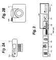
- the operating unit 9 includes a time axis operation dial.
- Fig. 2A shows an example of the time axis operation dial.
- a time axis operation dial 22a slightly protrudes from a rear surface and a side surface of a camera body 21.
- a time axis operation dial 22b is disposed on a top surface of the camera body 21.
- the time axis operation dials 22a and 22b have the same shape and sense of operation as a windup dial of a silver salt film camera. In other words, the time axis operation dials 22a and 22b can be rotated for a predetermined amount in each step. Viewed from the top surface of the camera body 21, the time axis operation dials 22a and 22b can be rotated in the clockwise direction and the counterclockwise direction. In the following description, the time axis operation dials 22a and 22b are generally referred to as the time dial 22.
- the time axis may be operated by an input device such as a cross key, a roller, a track ball, a touch panel, or the like.
- an input device such as a cross key, a roller, a track ball, a touch panel, or the like.
- edge portions of a cross shape operation portion of the cross key (these edge portions are referred to as a left button, a right button, an up button, and a down button) are pressed, moving directions of the cursor are designated to upward, downward, leftward, and right ward, respectively.
- the time dial 22 is not limited to a mechanical structure. Instead, a GUI (Graphical User Interface) that operates buttons or the like on the display screen may be used.
- Fig. 3 describes images displayed on the LCD 13 according to the embodiment.
- Reference letter R denotes an image that is currently being captured (hereinafter this image may be referred to as a currently captured image).
- Reference letter P denotes an image that has been captured and that is reproduced in the reproducing mode (thereinafter this image may be referred to as a reproduced image).
- the currently captured image R is followed by reproduced images P1, P2, P3, and so forth and arranged along the time axis.
- the right direction denotes a direction from the past to the present on the time axis
- the left direction denotes a direction from the present to the past on the time axis.
- the LCD 13 may be either an LCD having an aspect ratio of 4 to 3 or a wide LCD having an aspect ratio of for example 16 to 9.
- reference letter SC denotes a display frame for the wide LCD.
- the currently captured image R and the reproduced images P1 and P2 are displayed at the same time.
- the time dial 22 is rotated in the counterclockwise direction viewed from the top surface of the camera body 21, the time axis is varied from the present to the past.
- the size of the currently captured image R is larger than that of the reproduced image P. Instead, with different shape icons added to the currently captured image R and the reproduced image P, they may be distinguished.
- Fig. 4 schematically shows display data that form images displayed on the LCD 13 and that are stored in the internal record medium 3.
- the currently captured image R shown in Fig. 4A is stored in the internal record medium 3.
- the currently captured image R is updated at intervals of a frame or the like.
- Fig. 4B shows OSD data that are stored in the internal record medium 3 besides the currently captured data R.
- the OSD data are data of icons combined with the currently captured data R.
- the reproduced images P1 and P2 of a plurality of recently recorded images are stored in a storage area MC of the internal record medium 3 corresponding to the display frame SC.
- the reproduced image data P1 and P2 are read from the external record medium 11, decoded and size-reduced by the image processing unit 4, and then stored in the internal record medium 3.
- OSD display size images corresponding to images that have been just captured it is not necessary to read data from the external record medium 11.
- the size of the reproduced images P1 and P2 is smaller than that of the currently captured image R.
- the OSD data contain an icon 31 that indicates a currently captured image and an icon 32 that indicates a reproduced image. With these icons 31 and 32, the user can easily identify the types of the images. In the following description, illustrations of the icons 31 and 32 will be omitted.
- the OSD data may be composed of data having a plurality of hierarchical levels. As shown in Fig. 4C , the currently captured image R and the OSD data are combined and displayed on the wide type LCD 13.
- the display frame SC of the LCD 13 disposed on the rear surface of the digital camera is a wide type LCD having an aspect ratio of for example (16 : 9).
- Reference letter ST1 denotes a display screen that appears in a shooting mode. An image R of an object currently captured through a lens is displayed nearly at a center portion of the display frame SC. In the shooting mode, when a shutter button 24 is pressed, the object can be shot.
- a plurality of keys, buttons, and so forth are disposed on the rear surface of the digital camera. They are for example a menu button 25 and a delete button 26.
- the currently captured image R is moved rightward.
- the reproduced image P1 that has been just captured and obtained is displayed on the left of the currently captured image R.
- the reproduced image P2 captured before the reproduced image P1 is displayed on the left thereof.
- the display screen ST2 on which the currently captured image R and the reproduced images P1 and P2 are displayed at the same time is a co-existent state of the shooting mode and the reproducing mode. While the user is watching an image that has been just captured, he or she can decide a composition and so forth of an image that he or she will shoot.
- a display screen ST3 appears on which only the reproduced images P1, P2, P3, and P4 are displayed. This state is the reproducing mode. A plurality of reproduced images P1, P2, P3, and P4 are displayed along the time axis.
- Fig. 5 shows transitions of screens from the present to the past that take place when the time dial 22 is rotated in the counterclockwise direction viewed from the top surface of the camera body 21.
- the shooting mode and the reproducing mode can be switched as seamless operations.
- the rotating operation of the time dial 22, the mode switching, and the image switching have an affinity with the user's conceptual model. Thus, they have an excellent operability. Instead, the shooting mode and the reproducing mode may be directly switched not through the co-existent state thereof.
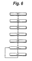
- Fig. 6 shows transitions of operations that take place when the time dial 22 is rotated.
- the time dial 22 is rotated in the counterclockwise direction viewed from the top surface of the camera body 21, the operations change from the top to the bottom shown in Fig. 6 .
- the time dial 22 is rotated in the clockwise direction viewed from the top surface of the camera body 21, operations change from the bottom to the top shown in Fig. 6 .
- step S2 the shooting mode
- step S3 the co-existent state of the shooting mode and the reproducing mode in which both the currently captured image R and the reproduced image P are displayed takes place.
- the moving of images is momentarily stopped. In other words, even if the time dial 22 is rotated, the moving of reproduced images is stopped. After a momentary stop time elapsed, the co-existent state of the shooting mode and the reproducing mode of step S3 takes place. Since the momentary stop state is provided, the user can know that the reproducing mode is switched to the shooting mode. Since the moving of reproduced images stops for a short time, it does not prevent modes from being seamlessly switched.
- the shooting mode, the co-existent mode of the shooting mode and reproducing mode, and the reproducing mode be indicated with animations corresponding to the operations of the time dial 22.
- Fig. 7 shows examples of animations of transitions of screens.
- a transition display screen ST14 When the time dial 22 is rotated for one more step, as displayed on a transition display screen ST14, the currently captured image R is gradually moved rightward and exited from the display frame SC. Thereafter, a display screen ST15 appears on which only the reproduced images P1, P2, and P3 are displayed as a reproducing mode. In the reproducing mode, a frame-shaped cursor denoted by solid lines indicates the reproduced image P1 that is being currently focused.
- the reproduced image P1 is exited from the screen and then the reproduced image P2 is focused.
- Reference letter ST101 denotes a normal display screen that appears when the power is turned on.
- a currently captured image R of an object that is being captured through the lens and a reproduced image P1 that has been just captured and obtained are displayed so that the currently captured image R is followed by the reproduced image P1 on the left thereof and they do not overlap. Since the currently captured image R and the reproduced image P1 do not overlap, the currently captured image can be prevented from being obstructed by the reproduced image.
- the reproduced image P1 is followed by a reproduced image P2 on the left thereof.
- the display screen ST101 on which the currently captured image R and reproduced images P1 and P2 are displayed at the same time is a co-existent state of the shooting mode and the reproducing mode.
- the shutter button 24 is pressed while the display screen ST101 appears, a new image can be recorded and a desired image can be displayed as a reproduced image.
- the user is watching an image that has been just captured, he or she can decide a composition and so forth of an image that he or she will shoot.
- Fig. 9 shows transitions of screens in the co-existent state of the shooting mode and the reproducing mode in which the currently captured image R and the reproduced images P1 and P2 are displayed at the same time when a delete button 26 is pressed.
- the delete button 26 is pressed while the transition screen ST111 appears, transitions to a display screen ST112 take place.
- a frame shaped cursor C is displayed at a position corresponding to the reproduced image P1 so that the cursor indicates that the reproduced image P1 has been selected.
- a deletion dialog 28 is displayed at the position of the currently captured image R. When the left button of the cross key 27 is pressed, a reproduced image on the left of the cursor C (namely, a reproduced image earlier than the reproduced image at the position of the cursor C) can be selected.
- the deletion dialog 28 has "delete” and "end” which can be selected by the up and down buttons of the cross key 27. The selected item is highlighted.
- a currently captured image R and reproduced images P1 and P2 are displayed in the display frame SC of the LCD 13.
- the display screen ST21 is a co-existent state of the shooting mode and the reproducing mode.
- the menu button 25 is pressed in this state, a menu with respect to the shooting mode is displayed in the display frame 13.
- a display screen ST22 appears on which the frame-shaped cursor C indicates the reproduced image P1.
- the state of which the reproduced image P1 is selected is the reproducing mode.
- An arrow cursor is also displayed beside the cursor C. The arrow cursor indicates that images on the left can be selected.
- transition display screen ST25 When the left button of the cross key 27 is pressed again, animations of transitions to a display screen through a transition display screen ST25 appear.
- the transition display screen ST25 momentarily appears.
- the cursor C On the display screen ST26, the cursor C indicates the reproduced image P3. Since reproduced images can be switched in both the directions, arrow cursors are displayed on both the sides.
- modes can be seamlessly switched.
- images can be switched having an affinity with the user's conceptual model.
- a reproduced image indicated by the cursor C can be displayed in an enlarged size or a reduced size.
- the reproducing mode will be described in detail.
- the selected image can be displayed in an enlarged size or a reduced size.
- Fig. 11 shows transitions of screens when a reproduced image is displayed in an enlarged size.
- a display screen ST26 is the same as the last display screen shown in Fig. 10 .
- a tele key or "OK" key is pressed.
- the tele key is a mechanical key disposed on the camera body, a GUI key, or the like.
- the "OK” key is a mechanical key disposed on the camera body, a GUI key, a center switch of the cross key 27, or the like.
- Animations of transitions of display screens until a display screen ST28 through a transition display screen ST27 appear according to the operation of the tele key or the "OK" key.
- Enlarged reproduced images P21, P31, and P41 displayed on the transition display screen ST27 are slightly larger than the original reproduced images P2, P3, and P4, respectively.
- An enlarged reproduced image P32 displayed at the center position on the display screen ST28 is larger than the reproduced image P31.
- Fig. 12 shows transitions of screens when an image is displayed in a reduced size.
- a display screen ST26 is the same as the last display screen shown in Fig. 10 .
- a wide key or the "OK" key is pressed.
- the wide key is a mechanical key of the camera body, a GUI key, or the like.
- the "OK” keys is a mechanical key disposed on the camera body, a GUI key, the center switch of the cross key 27, or the like.
- Animations of transitions of display screens until a display screen ST38 through a transition display screen ST37 appear according to the operation of the wide key or the "OK" key.
- Reduced reproduced images P13, P24, P33, P43, and P54 displayed on the transition display screen ST37 are slightly smaller than original reproduced images P1, P2, P3, and P4, respectively.
- a reduced reproduced image P34 displayed at the center position on the display screen ST38 is smaller than the reproduced image P33.
- the display frame SC of the LCD 13 is an oblong wide screen.
- an LCD having a display frame SC whose aspect ratio is (4 : 3) may be used instead of the wide screen.
- reference letter SC' denotes a display frame whose aspect ratio is (4 : 3).
- Reference letter ST41 denotes a display screen that is a shooting mode. A currently captured image R of an object through a lens is displayed nearly at the center portion of the display frame SC. When the shutter button 24 is pressed in the shooting mode, the object can be shot.
- the currently captured image R is reduced and moved rightward.
- a reproduced image P1 captured immediately before the currently captured image R is displayed on the left thereof.
- a display screen ST42 on which both the currently captured image R and the reproduced image P1 are displayed at the same time is a co-existent state of the shooting mode and the reproducing mode. While the user is watching an image that has been just captured, he or she can select a new image that he or she will shoot.
- a display screen ST43 appears on which only reproduced images P1, P2, and P3 are displayed. This state is the reproducing mode. A plurality of reproduced images P1, P2, and P3 are displayed along the time axis.
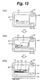
- Fig. 13 shows transitions of screens from the present to the past that take place when the time dial 22 is rotated in the counterclockwise direction viewed from the top surface of the camera body 21.
- the time dial 22 is rotated in the clockwise direction viewed from the top surface of the camera body 21, transitions of screens from the past to the present take place.
- the shooting mode and the reproducing mode can be seamlessly switched.
- the transitions of the shooting mode, the co-existent mode of the shooting mode and the reproducing mode, and the reproducing mode are represented by animations according to operations of the time dial 22.
- Fig. 14 shows examples of animations of transitions of screens.
- transitions of display screens through a transition display screen ST52 to a display screen ST53 take place on which the currently captured image R and reproduced images P1 and P2 are displayed at the same time.
- the currently captured image R is gradually moved rightward and a reproduced image is gradually entered from the left of the screen between the display screens ST51 and ST53.
- the reproduced image P1 is displayed adjacent to the currently captured image R on the display screen ST53.
- the currently captured image R is gradually moved rightward and exited from the display frame SC' as shown on a transition display screen ST54. Thereafter, a display screen ST55 appears. Only the reproduced images P1, P2, and P3 are displayed on the display screen ST55 that is a reproducing mode. In the reproducing mode, a frame-shaped cursor denoted by solid lines indicates the reproduced image P1 that is being currently focused.
- the reproduced image P1 is exited from the screen and the reproduced image P2 is focused (not shown).
- the present invention is not limited to the foregoing embodiment. Instead, various modifications and ramifications may be made without departing from the scope of the present invention.
- the present invention is not limited to a digital camera that records still images.
- the present invention may be applied to an imaging apparatus that records moving images and an imaging apparatus that can record both still images and moving images. When a moving image is recorded, for example the top image thereof is displayed on an LCD or the like.
Landscapes
- Engineering & Computer Science (AREA)
- General Engineering & Computer Science (AREA)
- Theoretical Computer Science (AREA)
- Human Computer Interaction (AREA)
- Physics & Mathematics (AREA)
- General Physics & Mathematics (AREA)
- Multimedia (AREA)
- Signal Processing (AREA)
- Studio Devices (AREA)
- Television Signal Processing For Recording (AREA)
Applications Claiming Priority (3)
| Application Number | Priority Date | Filing Date | Title |
|---|---|---|---|
| JP2004143439A JP5055685B2 (ja) | 2004-05-13 | 2004-05-13 | 撮像装置、画面表示方法およびユーザインターフェース |
| JP2004143438A JP2005328242A (ja) | 2004-05-13 | 2004-05-13 | 撮像装置、画面表示方法およびユーザインターフェース |
| PCT/JP2005/008658 WO2005112436A1 (ja) | 2004-05-13 | 2005-05-02 | 撮像装置、画面表示方法およびユーザインターフェース |
Publications (3)
| Publication Number | Publication Date |
|---|---|
| EP1746819A1 EP1746819A1 (en) | 2007-01-24 |
| EP1746819A4 EP1746819A4 (en) | 2007-10-17 |
| EP1746819B1 true EP1746819B1 (en) | 2012-05-23 |
Family
ID=35394522
Family Applications (1)
| Application Number | Title | Priority Date | Filing Date |
|---|---|---|---|
| EP05738836A Expired - Fee Related EP1746819B1 (en) | 2004-05-13 | 2005-05-02 | Imaging device, image display method, and user interface |
Country Status (5)
| Country | Link |
|---|---|
| US (5) | US7714926B2 (ko) |
| EP (1) | EP1746819B1 (ko) |
| KR (2) | KR101114195B1 (ko) |
| CN (2) | CN101959021B (ko) |
| WO (1) | WO2005112436A1 (ko) |
Families Citing this family (52)
| Publication number | Priority date | Publication date | Assignee | Title |
|---|---|---|---|---|
| KR101114195B1 (ko) | 2004-05-13 | 2012-02-22 | 소니 주식회사 | 촬상 장치, 화면 표시 방법 및 유저 인터페이스 |
| JP5055684B2 (ja) | 2004-05-13 | 2012-10-24 | ソニー株式会社 | 画像フォルダ切替装置 |
| KR20070092582A (ko) * | 2006-03-09 | 2007-09-13 | 삼성전자주식회사 | 영상 표시 및 저장 장치와 방법 |
| WO2007145004A1 (ja) * | 2006-06-13 | 2007-12-21 | Panasonic Corporation | 撮像装置 |
| USD609714S1 (en) * | 2007-03-22 | 2010-02-09 | Fujifilm Corporation | Electronic camera |
| JP4386097B2 (ja) * | 2007-06-04 | 2009-12-16 | ソニー株式会社 | 情報表示装置、撮像装置、および表示データ制御方法、並びにコンピュータ・プログラム |
| JP4995059B2 (ja) * | 2007-12-17 | 2012-08-08 | ペンタックスリコーイメージング株式会社 | デジタルカメラ |
| JP4960849B2 (ja) * | 2007-12-17 | 2012-06-27 | ペンタックスリコーイメージング株式会社 | デジタルカメラ |
| JP5116514B2 (ja) * | 2008-03-11 | 2013-01-09 | キヤノン株式会社 | 撮像装置および表示制御方法 |
| JP4931845B2 (ja) * | 2008-03-18 | 2012-05-16 | 富士フイルム株式会社 | 撮像装置及び撮影画像表示制御方法 |
| US8477228B2 (en) | 2008-06-30 | 2013-07-02 | Verizon Patent And Licensing Inc. | Camera data management and user interface apparatuses, systems, and methods |
| KR20100013705A (ko) * | 2008-07-31 | 2010-02-10 | 삼성디지털이미징 주식회사 | 디지털 영상 처리 장치, 그 제어 방법 및 이를 실행시키기위한 프로그램을 저장한 기록 매체 |
| KR101436841B1 (ko) * | 2008-08-19 | 2014-09-03 | 삼성전자주식회사 | 디지털 이미지 처리장치 |
| JP5393190B2 (ja) | 2009-02-17 | 2014-01-22 | キヤノン株式会社 | 表示制御装置、表示制御装置の制御方法、プログラム、及び記録媒体 |
| US9148618B2 (en) * | 2009-05-29 | 2015-09-29 | Apple Inc. | Systems and methods for previewing newly captured image content and reviewing previously stored image content |
| JP2011033870A (ja) * | 2009-08-03 | 2011-02-17 | Sony Corp | 画像処理装置、画像処理方法およびプログラム |
| JP5581628B2 (ja) * | 2009-08-05 | 2014-09-03 | ソニー株式会社 | 表示制御装置、表示制御方法及び表示制御プログラム |
| EP2495953A4 (en) * | 2009-10-27 | 2015-11-25 | Nec Casio Mobile Comm Ltd | IMAGE RECORDING AND IMAGE RECORDING |
| US8239783B2 (en) * | 2009-11-19 | 2012-08-07 | Microsoft Corporation | Integrated viewfinder and digital media |
| CN102404525A (zh) * | 2010-09-16 | 2012-04-04 | 宏碁股份有限公司 | 一种电视播放介面及播放方法 |
| JP5136624B2 (ja) * | 2010-11-25 | 2013-02-06 | カシオ計算機株式会社 | 撮像装置、撮像方法及びプログラム |
| KR101839473B1 (ko) | 2011-08-03 | 2018-03-19 | 삼성전자주식회사 | 비교 영상 제공 방법 및 이를 적용한 영상 촬영 장치 |
| JP5806623B2 (ja) * | 2012-02-07 | 2015-11-10 | オリンパス株式会社 | 撮像装置、撮像方法およびプログラム |
| US20130314558A1 (en) * | 2012-05-24 | 2013-11-28 | Mediatek Inc. | Image capture device for starting specific action in advance when determining that specific action is about to be triggered and related image capture method thereof |
| EP4171052A1 (en) | 2012-06-11 | 2023-04-26 | Sony Group Corporation | Control device, control method, and recording medium |
| JP2013257686A (ja) * | 2012-06-12 | 2013-12-26 | Sony Corp | 投影型画像表示装置及び画像投影方法、並びにコンピューター・プログラム |
| KR101935039B1 (ko) * | 2012-09-11 | 2019-01-03 | 엘지전자 주식회사 | 이동 단말기 및 이동 단말기의 제어 방법 |
| KR101969424B1 (ko) * | 2012-11-26 | 2019-08-13 | 삼성전자주식회사 | 촬영된 이미지를 표시하는 촬영 장치 및 그 촬영 방법 |
| JP5725049B2 (ja) * | 2013-01-24 | 2015-05-27 | カシオ計算機株式会社 | 撮像装置、撮像方法及びプログラム |
| JP2014165609A (ja) * | 2013-02-22 | 2014-09-08 | Olympus Imaging Corp | 撮影機器 |
| USD738394S1 (en) | 2013-06-09 | 2015-09-08 | Apple Inc. | Display screen or portion thereof with animated graphical user interface |
| USD741350S1 (en) | 2013-06-10 | 2015-10-20 | Apple Inc. | Display screen or portion thereof with animated graphical user interface |
| KR102047703B1 (ko) * | 2013-08-09 | 2019-11-22 | 엘지전자 주식회사 | 이동 단말기 및 이의 제어 방법 |
| KR102065410B1 (ko) * | 2013-09-04 | 2020-01-13 | 엘지전자 주식회사 | 이동 단말기 및 이의 제어 방법 |
| JP5768989B2 (ja) * | 2013-09-06 | 2015-08-26 | 第一精工株式会社 | 同軸コネクタ装置 |
| USD772278S1 (en) | 2013-12-18 | 2016-11-22 | Apple Inc. | Display screen or portion thereof with animated graphical user interface |
| US9811245B2 (en) | 2013-12-24 | 2017-11-07 | Dropbox, Inc. | Systems and methods for displaying an image capturing mode and a content viewing mode |
| USD769892S1 (en) | 2014-05-30 | 2016-10-25 | Apple Inc. | Display screen or portion thereof with graphical user interface |
| USD767613S1 (en) * | 2015-05-01 | 2016-09-27 | Microsoft Corporation | Display screen with animated graphical user interface |
| USD765699S1 (en) | 2015-06-06 | 2016-09-06 | Apple Inc. | Display screen or portion thereof with graphical user interface |
| KR20170013555A (ko) * | 2015-07-28 | 2017-02-07 | 엘지전자 주식회사 | 이동단말기 및 그 제어방법 |
| CN105245763B (zh) * | 2015-09-28 | 2018-11-06 | 北京方瑞博石数字技术有限公司 | 一种微电影的拍摄系统 |
| US10547776B2 (en) | 2016-09-23 | 2020-01-28 | Apple Inc. | Devices, methods, and graphical user interfaces for capturing and recording media in multiple modes |
| USD868804S1 (en) * | 2017-01-20 | 2019-12-03 | Twitter, Inc. | Display screen with a transitional graphical user interface |
| USD846587S1 (en) | 2017-06-04 | 2019-04-23 | Apple Inc. | Display screen or portion thereof with animated graphical user interface |
| USD877175S1 (en) | 2018-06-04 | 2020-03-03 | Apple Inc. | Electronic device with graphical user interface |
| USD923653S1 (en) * | 2018-09-11 | 2021-06-29 | Delta Electronics, Inc. | Display screen with graphical user interface |
| USD883319S1 (en) | 2018-10-29 | 2020-05-05 | Apple Inc. | Electronic device with graphical user interface |
| CN109413333B (zh) * | 2018-11-28 | 2022-04-01 | 维沃移动通信有限公司 | 一种显示控制方法及终端 |
| USD945470S1 (en) * | 2018-12-27 | 2022-03-08 | Sony Corporation | Display panel or screen with animated graphical user interface |
| JP7110163B2 (ja) * | 2019-09-13 | 2022-08-01 | 富士フイルム株式会社 | 画像処理装置、撮影装置、画像処理方法、及び画像処理プログラム |
| CN111265867B (zh) * | 2020-01-20 | 2021-06-29 | 腾讯科技(深圳)有限公司 | 对局画面的显示方法、装置、终端及存储介质 |
Family Cites Families (37)
| Publication number | Priority date | Publication date | Assignee | Title |
|---|---|---|---|---|
| US5138460A (en) * | 1987-08-20 | 1992-08-11 | Canon Kabushiki Kaisha | Apparatus for forming composite images |
| JP2697831B2 (ja) | 1987-11-04 | 1998-01-14 | キヤノン株式会社 | 再生装置 |
| CN1148954A (zh) | 1995-10-24 | 1997-05-07 | 李军 | 全自动多功能防褥按摩保健气动床 |
| JP3630862B2 (ja) * | 1996-07-18 | 2005-03-23 | キヤノン株式会社 | 撮像装置及び方法 |
| JP3847915B2 (ja) | 1997-09-10 | 2006-11-22 | キヤノン株式会社 | 情報処理方法及び装置 |
| JPH10164433A (ja) | 1996-12-04 | 1998-06-19 | Fujitsu Ltd | 画面切り替え方法及び装置 |
| JPH10243273A (ja) * | 1997-02-24 | 1998-09-11 | Canon Inc | デジタルカメラ用画像表示方法 |
| US6069606A (en) * | 1997-05-15 | 2000-05-30 | Sony Corporation | Display of multiple images based on a temporal relationship among them with various operations available to a user as a function of the image size |
| US6233015B1 (en) * | 1997-06-27 | 2001-05-15 | Eastman Kodak Company | Camera with user compliant browse and display modes |
| US6137534A (en) * | 1997-07-10 | 2000-10-24 | Flashpoint Technology, Inc. | Method and apparatus for providing live view and instant review in an image capture device |
| US6122003A (en) * | 1997-08-22 | 2000-09-19 | Flashpoint Technology, Inc. | Method and apparatus for changing operating modes of an image capture device |
| EP0899666B1 (en) | 1997-08-25 | 2003-07-09 | Sharp Kabushiki Kaisha | Image processing apparatus displaying a catalog of different types of data in different manner |
| JP3403324B2 (ja) | 1997-08-25 | 2003-05-06 | シャープ株式会社 | 画像入出力装置 |
| WO1999012341A1 (en) | 1997-09-03 | 1999-03-11 | Casio Computer Co., Ltd. | Electronic still camera having photographed image reproducing function |
| US7136096B1 (en) * | 1998-03-11 | 2006-11-14 | Canon Kabushiki Kaisha | Image processing method and apparatus, control method therefor, and storage medium |
| JP2001128051A (ja) * | 1999-10-27 | 2001-05-11 | Ricoh Co Ltd | 撮像装置 |
| US6456323B1 (en) * | 1999-12-31 | 2002-09-24 | Stmicroelectronics, Inc. | Color correction estimation for panoramic digital camera |
| JP2001313861A (ja) | 2000-02-21 | 2001-11-09 | Fujitsu Ltd | 画像撮影装置、データ管理装置、媒体、およびプログラム |
| EP1128656A3 (en) * | 2000-02-21 | 2002-01-09 | Fujitsu Limited | Image photographing system having data management function, data management device and storage medium |
| EP1290571A4 (en) | 2000-04-17 | 2005-11-02 | Igt Reno Nev | SYSTEM AND METHOD FOR DETECTING THE PICTURE OF A PLAYER TO INTEGRATE IT INTO A GAME |
| JP2001320610A (ja) | 2000-05-02 | 2001-11-16 | Nikon Corp | 電子スチルカメラ |
| US6680845B2 (en) | 2000-09-06 | 2004-01-20 | Sony Corporation | Information processing apparatus |
| JP4573077B2 (ja) | 2000-09-06 | 2010-11-04 | ソニー株式会社 | 情報処理装置 |
| KR20020023638A (ko) * | 2000-09-22 | 2002-03-29 | 니시무로 타이죠 | 촬영장치 및 촬영방법 |
| JP3914705B2 (ja) * | 2000-11-29 | 2007-05-16 | 富士フイルム株式会社 | ディジタル・カメラおよびその動作制御方法 |
| US6887157B2 (en) | 2001-08-09 | 2005-05-03 | Igt | Virtual cameras and 3-D gaming environments in a gaming machine |
| US6970200B2 (en) | 2001-10-26 | 2005-11-29 | Hewlett-Packard Development Company, L.P. | System and method for a simplified digital camera interface for viewing images and controlling camera operation |
| JP2003209719A (ja) | 2002-01-16 | 2003-07-25 | Toshiba Corp | デジタルスチルカメラ |
| JP2003263256A (ja) | 2002-03-11 | 2003-09-19 | Omron Corp | ウインドウ表示方法 |
| JP3977684B2 (ja) * | 2002-05-21 | 2007-09-19 | 株式会社東芝 | デジタルスチルカメラ |
| JP2004072727A (ja) * | 2002-06-11 | 2004-03-04 | Sanyo Electric Co Ltd | 画像処理方法、画像処理装置、画像記録再生装置、およびテレビジョン受像機 |
| EP1430709B1 (en) | 2002-08-28 | 2007-07-18 | Casio Computer Co., Ltd. | Image and audio reproducing apparatus, image and audio reproducing method and program |
| JP2004254256A (ja) * | 2003-02-24 | 2004-09-09 | Casio Comput Co Ltd | カメラ装置、表示方法及びプログラム |
| JP2005176136A (ja) * | 2003-12-12 | 2005-06-30 | Canon Inc | 画像処理装置、画像再生方法、プログラムおよび記憶媒体 |
| JP5055684B2 (ja) | 2004-05-13 | 2012-10-24 | ソニー株式会社 | 画像フォルダ切替装置 |
| KR101114195B1 (ko) * | 2004-05-13 | 2012-02-22 | 소니 주식회사 | 촬상 장치, 화면 표시 방법 및 유저 인터페이스 |
| KR101058019B1 (ko) * | 2004-11-10 | 2011-08-19 | 삼성전자주식회사 | 통합 디스플레이 모드가 수행되는 디지털 촬영 장치의제어 방법, 및 이 방법을 채용한 디지털 촬영 장치 |
-
2005
- 2005-05-02 KR KR1020067019748A patent/KR101114195B1/ko not_active IP Right Cessation
- 2005-05-02 CN CN201010282287.3A patent/CN101959021B/zh not_active Expired - Fee Related
- 2005-05-02 US US11/568,810 patent/US7714926B2/en not_active Expired - Fee Related
- 2005-05-02 EP EP05738836A patent/EP1746819B1/en not_active Expired - Fee Related
- 2005-05-02 WO PCT/JP2005/008658 patent/WO2005112436A1/ja not_active Application Discontinuation
- 2005-05-02 KR KR1020117018092A patent/KR101164374B1/ko active IP Right Grant
- 2005-05-02 CN CN2005800104739A patent/CN1947412B/zh not_active Expired - Fee Related
-
2010
- 2010-03-30 US US12/750,179 patent/US8218057B2/en not_active Expired - Fee Related
-
2012
- 2012-06-04 US US13/487,672 patent/US8648954B2/en not_active Expired - Fee Related
- 2012-11-28 US US13/687,011 patent/US20130155310A1/en not_active Abandoned
-
2013
- 2013-12-17 US US14/108,693 patent/US9497382B2/en not_active Expired - Fee Related
Also Published As
| Publication number | Publication date |
|---|---|
| KR20110094152A (ko) | 2011-08-19 |
| CN101959021A (zh) | 2011-01-26 |
| WO2005112436A1 (ja) | 2005-11-24 |
| US20160119547A1 (en) | 2016-04-28 |
| US20130155310A1 (en) | 2013-06-20 |
| US20120274831A1 (en) | 2012-11-01 |
| US7714926B2 (en) | 2010-05-11 |
| US8648954B2 (en) | 2014-02-11 |
| US8218057B2 (en) | 2012-07-10 |
| KR20070014136A (ko) | 2007-01-31 |
| US20100182481A1 (en) | 2010-07-22 |
| CN1947412A (zh) | 2007-04-11 |
| EP1746819A4 (en) | 2007-10-17 |
| US9497382B2 (en) | 2016-11-15 |
| KR101164374B1 (ko) | 2012-07-09 |
| CN1947412B (zh) | 2011-06-15 |
| KR101114195B1 (ko) | 2012-02-22 |
| US20070188646A1 (en) | 2007-08-16 |
| EP1746819A1 (en) | 2007-01-24 |
| CN101959021B (zh) | 2015-02-11 |
Similar Documents
| Publication | Publication Date | Title |
|---|---|---|
| EP1746819B1 (en) | Imaging device, image display method, and user interface | |
| US9116610B2 (en) | Imaging apparatus and user interface | |
| US8972867B1 (en) | Method and apparatus for editing heterogeneous media objects in a digital imaging device | |
| US7471890B2 (en) | Mobile communication terminal with dual-display unit having function of editing captured image and method thereof | |
| US20050086611A1 (en) | Display method and display device | |
| US20100088643A1 (en) | Display apparatus, display method, program and storage medium | |
| JP2005328242A (ja) | 撮像装置、画面表示方法およびユーザインターフェース | |
| JP5055685B2 (ja) | 撮像装置、画面表示方法およびユーザインターフェース | |
| JP2006115044A (ja) | 撮像装置、レイアウト編集方法およびプログラム | |
| JP2000217014A (ja) | 選択方法および電子撮像装置 | |
| JP4840488B2 (ja) | 撮像装置、画面表示方法およびユーザインターフェース | |
| JP5212535B2 (ja) | 画面表示装置および画面表示方法 | |
| JP2006115045A (ja) | 撮像装置、撮像方法、プログラムおよびユーザインターフェース |
Legal Events
| Date | Code | Title | Description |
|---|---|---|---|
| PUAI | Public reference made under article 153(3) epc to a published international application that has entered the european phase |
Free format text: ORIGINAL CODE: 0009012 |
|
| 17P | Request for examination filed |
Effective date: 20061108 |
|
| AK | Designated contracting states |
Kind code of ref document: A1 Designated state(s): DE ES FR GB IT NL |
|
| DAX | Request for extension of the european patent (deleted) | ||
| RBV | Designated contracting states (corrected) |
Designated state(s): DE ES FR GB IT NL |
|
| A4 | Supplementary search report drawn up and despatched |
Effective date: 20070914 |
|
| RIC1 | Information provided on ipc code assigned before grant |
Ipc: H04N 5/232 20060101AFI20070910BHEP |
|
| 17Q | First examination report despatched |
Effective date: 20080506 |
|
| GRAP | Despatch of communication of intention to grant a patent |
Free format text: ORIGINAL CODE: EPIDOSNIGR1 |
|
| GRAS | Grant fee paid |
Free format text: ORIGINAL CODE: EPIDOSNIGR3 |
|
| GRAA | (expected) grant |
Free format text: ORIGINAL CODE: 0009210 |
|
| AK | Designated contracting states |
Kind code of ref document: B1 Designated state(s): DE ES FR GB IT NL |
|
| REG | Reference to a national code |
Ref country code: GB Ref legal event code: FG4D |
|
| REG | Reference to a national code |
Ref country code: DE Ref legal event code: R081 Ref document number: 602005034312 Country of ref document: DE Owner name: THOMSON LICENSING SAS, FR Free format text: FORMER OWNER: SONY CORPORATION, TOKIO/TOKYO, JP |
|
| REG | Reference to a national code |
Ref country code: DE Ref legal event code: R096 Ref document number: 602005034312 Country of ref document: DE Effective date: 20120719 |
|
| REG | Reference to a national code |
Ref country code: NL Ref legal event code: T3 |
|
| PG25 | Lapsed in a contracting state [announced via postgrant information from national office to epo] |
Ref country code: IT Free format text: LAPSE BECAUSE OF FAILURE TO SUBMIT A TRANSLATION OF THE DESCRIPTION OR TO PAY THE FEE WITHIN THE PRESCRIBED TIME-LIMIT Effective date: 20120523 |
|
| PLBE | No opposition filed within time limit |
Free format text: ORIGINAL CODE: 0009261 |
|
| STAA | Information on the status of an ep patent application or granted ep patent |
Free format text: STATUS: NO OPPOSITION FILED WITHIN TIME LIMIT |
|
| PG25 | Lapsed in a contracting state [announced via postgrant information from national office to epo] |
Ref country code: ES Free format text: LAPSE BECAUSE OF FAILURE TO SUBMIT A TRANSLATION OF THE DESCRIPTION OR TO PAY THE FEE WITHIN THE PRESCRIBED TIME-LIMIT Effective date: 20120903 |
|
| 26N | No opposition filed |
Effective date: 20130226 |
|
| REG | Reference to a national code |
Ref country code: DE Ref legal event code: R097 Ref document number: 602005034312 Country of ref document: DE Effective date: 20130226 |
|
| REG | Reference to a national code |
Ref country code: FR Ref legal event code: TP Owner name: THOMSON LICENSING SA, FR Effective date: 20150623 |
|
| REG | Reference to a national code |
Ref country code: FR Ref legal event code: PLFP Year of fee payment: 12 |
|
| REG | Reference to a national code |
Ref country code: DE Ref legal event code: R082 Ref document number: 602005034312 Country of ref document: DE Representative=s name: MITSCHERLICH, PATENT- UND RECHTSANWAELTE PARTM, DE Ref country code: DE Ref legal event code: R082 Ref document number: 602005034312 Country of ref document: DE Representative=s name: HOFSTETTER, SCHURACK & PARTNER PATENT- UND REC, DE Ref country code: DE Ref legal event code: R081 Ref document number: 602005034312 Country of ref document: DE Owner name: THOMSON LICENSING SAS, FR Free format text: FORMER OWNER: SONY CORPORATION, TOKIO/TOKYO, JP |
|
| REG | Reference to a national code |
Ref country code: GB Ref legal event code: 732E Free format text: REGISTERED BETWEEN 20170406 AND 20170412 |
|
| REG | Reference to a national code |
Ref country code: FR Ref legal event code: PLFP Year of fee payment: 13 |
|
| REG | Reference to a national code |
Ref country code: DE Ref legal event code: R082 Ref document number: 602005034312 Country of ref document: DE Representative=s name: HOFSTETTER, SCHURACK & PARTNER PATENT- UND REC, DE |
|
| REG | Reference to a national code |
Ref country code: FR Ref legal event code: PLFP Year of fee payment: 14 |
|
| PGFP | Annual fee paid to national office [announced via postgrant information from national office to epo] |
Ref country code: NL Payment date: 20180412 Year of fee payment: 14 |
|
| PGFP | Annual fee paid to national office [announced via postgrant information from national office to epo] |
Ref country code: DE Payment date: 20180518 Year of fee payment: 14 |
|
| PGFP | Annual fee paid to national office [announced via postgrant information from national office to epo] |
Ref country code: FR Payment date: 20180523 Year of fee payment: 14 |
|
| PGFP | Annual fee paid to national office [announced via postgrant information from national office to epo] |
Ref country code: GB Payment date: 20180524 Year of fee payment: 14 |
|
| REG | Reference to a national code |
Ref country code: DE Ref legal event code: R119 Ref document number: 602005034312 Country of ref document: DE |
|
| REG | Reference to a national code |
Ref country code: NL Ref legal event code: MM Effective date: 20190601 |
|
| GBPC | Gb: european patent ceased through non-payment of renewal fee |
Effective date: 20190502 |
|
| PG25 | Lapsed in a contracting state [announced via postgrant information from national office to epo] |
Ref country code: DE Free format text: LAPSE BECAUSE OF NON-PAYMENT OF DUE FEES Effective date: 20191203 Ref country code: NL Free format text: LAPSE BECAUSE OF NON-PAYMENT OF DUE FEES Effective date: 20190601 Ref country code: GB Free format text: LAPSE BECAUSE OF NON-PAYMENT OF DUE FEES Effective date: 20190502 |
|
| PG25 | Lapsed in a contracting state [announced via postgrant information from national office to epo] |
Ref country code: FR Free format text: LAPSE BECAUSE OF NON-PAYMENT OF DUE FEES Effective date: 20190531 |