EP1742401A1 - Appareil recepteur ofdm et procede de reception ofdm - Google Patents
Appareil recepteur ofdm et procede de reception ofdm Download PDFInfo
- Publication number
- EP1742401A1 EP1742401A1 EP20050737200 EP05737200A EP1742401A1 EP 1742401 A1 EP1742401 A1 EP 1742401A1 EP 20050737200 EP20050737200 EP 20050737200 EP 05737200 A EP05737200 A EP 05737200A EP 1742401 A1 EP1742401 A1 EP 1742401A1
- Authority
- EP
- European Patent Office
- Prior art keywords
- carrier
- power
- interference
- calculation section
- signal
- Prior art date
- Legal status (The legal status is an assumption and is not a legal conclusion. Google has not performed a legal analysis and makes no representation as to the accuracy of the status listed.)
- Withdrawn
Links
- 238000000034 method Methods 0.000 title claims description 25
- 238000004364 calculation method Methods 0.000 claims abstract description 240
- 230000004044 response Effects 0.000 claims abstract description 158
- 239000000969 carrier Substances 0.000 claims description 22
- 238000012935 Averaging Methods 0.000 claims description 7
- 230000010354 integration Effects 0.000 claims description 5
- 238000010586 diagram Methods 0.000 description 40
- 239000013256 coordination polymer Substances 0.000 description 28
- 230000005540 biological transmission Effects 0.000 description 23
- 239000013598 vector Substances 0.000 description 22
- 238000012937 correction Methods 0.000 description 20
- 101100181504 Mus musculus Clc gene Proteins 0.000 description 14
- 238000001514 detection method Methods 0.000 description 9
- 238000006243 chemical reaction Methods 0.000 description 7
- 230000003111 delayed effect Effects 0.000 description 6
- 230000006866 deterioration Effects 0.000 description 6
- 238000011161 development Methods 0.000 description 3
- 230000007423 decrease Effects 0.000 description 2
- 230000000694 effects Effects 0.000 description 2
- 230000006870 function Effects 0.000 description 2
- 238000003780 insertion Methods 0.000 description 1
- 230000037431 insertion Effects 0.000 description 1
- 238000004519 manufacturing process Methods 0.000 description 1
- 230000010363 phase shift Effects 0.000 description 1
- 230000000087 stabilizing effect Effects 0.000 description 1
Images


Classifications
-
- H—ELECTRICITY
- H04—ELECTRIC COMMUNICATION TECHNIQUE
- H04L—TRANSMISSION OF DIGITAL INFORMATION, e.g. TELEGRAPHIC COMMUNICATION
- H04L27/00—Modulated-carrier systems
- H04L27/26—Systems using multi-frequency codes
- H04L27/2601—Multicarrier modulation systems
- H04L27/2647—Arrangements specific to the receiver only
- H04L27/2649—Demodulators
- H04L27/265—Fourier transform demodulators, e.g. fast Fourier transform [FFT] or discrete Fourier transform [DFT] demodulators
-
- H—ELECTRICITY
- H04—ELECTRIC COMMUNICATION TECHNIQUE
- H04L—TRANSMISSION OF DIGITAL INFORMATION, e.g. TELEGRAPHIC COMMUNICATION
- H04L1/00—Arrangements for detecting or preventing errors in the information received
- H04L1/20—Arrangements for detecting or preventing errors in the information received using signal quality detector
-
- H—ELECTRICITY
- H04—ELECTRIC COMMUNICATION TECHNIQUE
- H04B—TRANSMISSION
- H04B17/00—Monitoring; Testing
- H04B17/30—Monitoring; Testing of propagation channels
- H04B17/309—Measuring or estimating channel quality parameters
-
- H—ELECTRICITY
- H04—ELECTRIC COMMUNICATION TECHNIQUE
- H04L—TRANSMISSION OF DIGITAL INFORMATION, e.g. TELEGRAPHIC COMMUNICATION
- H04L27/00—Modulated-carrier systems
- H04L27/26—Systems using multi-frequency codes
- H04L27/2601—Multicarrier modulation systems
- H04L27/2614—Peak power aspects
- H04L27/2623—Reduction thereof by clipping
-
- H—ELECTRICITY
- H04—ELECTRIC COMMUNICATION TECHNIQUE
- H04L—TRANSMISSION OF DIGITAL INFORMATION, e.g. TELEGRAPHIC COMMUNICATION
- H04L27/00—Modulated-carrier systems
- H04L27/26—Systems using multi-frequency codes
- H04L27/2601—Multicarrier modulation systems
- H04L27/2647—Arrangements specific to the receiver only
- H04L27/2649—Demodulators
- H04L27/26524—Fast Fourier transform [FFT] or discrete Fourier transform [DFT] demodulators in combination with other circuits for demodulation
-
- H—ELECTRICITY
- H04—ELECTRIC COMMUNICATION TECHNIQUE
- H04L—TRANSMISSION OF DIGITAL INFORMATION, e.g. TELEGRAPHIC COMMUNICATION
- H04L27/00—Modulated-carrier systems
- H04L27/26—Systems using multi-frequency codes
- H04L27/2601—Multicarrier modulation systems
- H04L27/2647—Arrangements specific to the receiver only
- H04L27/2655—Synchronisation arrangements
- H04L27/2668—Details of algorithms
- H04L27/2681—Details of algorithms characterised by constraints
- H04L27/2682—Precision
-
- H—ELECTRICITY
- H04—ELECTRIC COMMUNICATION TECHNIQUE
- H04L—TRANSMISSION OF DIGITAL INFORMATION, e.g. TELEGRAPHIC COMMUNICATION
- H04L27/00—Modulated-carrier systems
- H04L27/26—Systems using multi-frequency codes
- H04L27/2601—Multicarrier modulation systems
- H04L27/2647—Arrangements specific to the receiver only
-
- H—ELECTRICITY
- H04—ELECTRIC COMMUNICATION TECHNIQUE
- H04L—TRANSMISSION OF DIGITAL INFORMATION, e.g. TELEGRAPHIC COMMUNICATION
- H04L5/00—Arrangements affording multiple use of the transmission path
- H04L5/003—Arrangements for allocating sub-channels of the transmission path
- H04L5/0044—Allocation of payload; Allocation of data channels, e.g. PDSCH or PUSCH
Definitions
- the present invention relates to an apparatus and a method for receiving a signal which is modulated using an Orthogonal Frequency Division Multiplexing (OFDM) technique and is transmitted.
- OFDM Orthogonal Frequency Division Multiplexing
- OFDM is used as a transmission technique for digital terrestrial broadcasting in Europe and Japan, wireless LAN, and the like.
- the OFDM technique is a method of performing modulation/demodulation by assigning data to a plurality of carriers orthogonal to each other.
- An Inverse Fast Fourier Transform (IFFT) process is performed in a transmitter, while a Fast Fourier Transform (FFT) process is performed in a receiver.
- Any modulation method can be employed with respect to each carrier, including QPSK (Quaternary Phase Shift Keying), QAM (Quadrature Amplitude Modulation), and the like.
- a position and an orientation of the antenna may be adjusted and optimized while observing a reception state of a receiver, i.e., a signal quality value of a received signal (see Patent Document 1 below).
- the signal quality value of a received signal may be used for a control of AGC (Automatic Gain Control) for stabilizing a gain of a received signal selected by a tuner (see Patent Document 2 below).
- Patent Document 1 An example of such a technique of detecting the signal quality value of a received signal is disclosed in Patent Document 1.
- Patent Document 1 describes that an SP (scattered pilot) signal which is inserted every three carriers is used to detect an S/N value so as to detect a signal quality value (S/N value) corresponding to the reception quality of whole received data even when there is frequency selective interference, such as multipath interference or the like.
- Patent Document 1 also describes a technique of applying fluctuations in channel responses in a frequency direction and a time direction to correction of the S/N value so as to reflect on the S/N value a deterioration in bit error rate due to the fluctuation of the channel response, when there is multipath interference, reception is performed during moving, or the like.
- Patent Document 1 also describes a technique of correcting the S/N value, depending on the number of interfered carriers so as to detect an S/N value corresponding to the reception quality of whole received data, even when specific carriers in a received signal are interfered with.
- Patent Document 3 discloses an exemplary circuit which detects a fluctuation in channel response, depending on a frequency.
- an interference detecting circuit is required for each kind of interference, depending on the property of the kind of interference. This leads to an increase in circuit scale, development cost and manufacturing cost of apparatuses.
- An object of the present invention is to estimate a degree of influence of interference on an OFDM received signal, with high accuracy, even under various interference conditions.
- the present invention provides an OFDM reception apparatus for receiving and demodulating an OFDM (Orthogonal Frequency Division Multiplexing) signal composed of a plurality of carriers including a carrier transmitting a pilot signal which is inserted at predetermined symbol intervals.
- the apparatus comprises a fast Fourier transform section for converting a received OFDM signal into a frequency-domain OFDM signal and outputting the frequency-domain OFDM signal, a channel response calculation section for obtaining a channel response with respect to the carrier transmitting the pilot signal, from the frequency-domain OFDM signal, an interpolation section for interpolating the channel response with respect to the carrier transmitting the pilot signal, and outputting the result, a power calculation section for calculating the square of a magnitude of the interpolated channel response obtained in the interpolation section, as a carrier power, for each carrier corresponding to the channel response, an interference calculation section for calculating a degree of an influence of interference on the received OFDM signal, as an interference power, for each carrier corresponding to the interpolated channel response, and a carrier quality
- the degree of the influence of interference on a received OFDM signal can be estimated even under various interference conditions while avoiding an increase in circuit scale and a reduction in development efficiency. Therefore, it is possible to correctly obtain the signal quality value of a received signal, appropriately control a gain with respect to the received signal, and improve performance of demodulation and error correction.
- AGC control section gain control section
- FFT section fast Fourier transform section
- demodulation section channel response calculation section
- interpolation section 32, 532, 632 soft decision section
- power calculation section 44 average calculation section 50, 150, 650 interference calculation section 60, 560, 660 carrier quality calculation section 70, 270, 370, 470 noise power calculation section 80, 380 noise power candidate calculation section
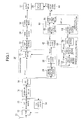
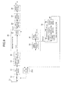
- FIG. 1 is a block diagram illustrating an exemplary configuration of an OFDM reception apparatus according to a first embodiment of the present invention.
- the OFDM reception apparatus of FIG. 1 comprises a tuner 12, an A/D conversion section 13, an AGC control section 14 (gain control section), a quadrature demodulation section 16, an FFT section (fast Fourier transform section) 18, a demodulation section 20, a soft decision section 32, an error correction section 34, a source decoding section 36, output sections 37 and 38, a power calculation section 42, an average calculation section 44, an interference calculation section 50, and a carrier quality calculation section 60.
- An antenna 11 receives an RF (radio frequency) OFDM signal and outputs the OFDM signal to the tuner 12.
- the tuner 12 selects a desired RF OFDM signal from the RF OFDM signal received from the antenna 11 while performing a gain control based on an AGC control signal from the AGC control section 14, frequency-converts the selected OFDM signal into an IF (intermediate frequency) OFDM signal, and outputs the IF OFDM signal to the A/D conversion section 13.
- the A/D conversion section 13 samples and converts the IF OFDM signal (analog signal) into a digitized IF OFDM signal, and outputs the digitized IF OFDM signal to the AGC control section 14 and the quadrature demodulation section 16.
- the AGC control section 14 generates an AGC control signal based on an average level of an input signal so that an amplitude of the input signal goes to a predetermined level, and outputs the AGC control signal to the tuner 12.
- the quadrature demodulation section 16 converts the digitized IF OFDM signal into a baseband OFDM signal, and outputs the baseband OFDM signal to the FFT section 18.
- the FFT section 18 performs Fourier transform with respect to the baseband OFDM signal. Specifically, the time-domain OFDM signal is converted into a frequency-domain OFDM signal Y ( ⁇ ), which is in turn output to the demodulation section 20.
- ⁇ is an integer indicating an index of a carrier constituting the frequency-domain OFDM signal.
- the output of the FFT section 18 indicates a phase and an amplitude of each carrier of the OFDM signal, and specifically, is represented in the form of a complex signal (vector) having an i-axis component and a q-axis component independently.
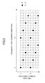
- FIG. 2 is a diagram illustrating an exemplary transmission format about a carrier arrangement of the frequency-domain OFDM signal Y ( ⁇ ).
- FIG. 2 illustrates, as an example, a portion of the digital terrestrial television broadcasting standards in Japan.
- an open circle D indicates a position of a data signal which transmits information, such as video, audio or the like
- a closed circle P indicates a position of a pilot signal.
- the pilot signal is also called an SP signal, and is equally spaced and inserted at a rate of one symbol every four symbols in one carrier every three carriers.
- the amplitude, phase and insertion position of the pilot signal are already known to the receiver.
- the demodulation section 20 estimates frequency characteristics of a transmission channel on which the received OFDM signal has been transmitted (hereinafter referred to as a channel response). Specifically, the demodulation section 20 calculates channel responses He( ⁇ ) with respect to all carriers, and based on the estimated channel responses He ( ⁇ ), performs waveform equalization with respect to the frequency-domain OFDM signal Y ( ⁇ ) to obtain a demodulated signal Xe ( ⁇ ), and outputs the demodulated signal Xe ( ⁇ ) to the soft decision section 32.
- the demodulation section 20 calculates channel responses He( ⁇ p) of pilot carriers from the frequency-domain OFDM signal Y ( ⁇ ) and outputs the channel responses He( ⁇ p) to the interference calculation section 50, and also calculates channel responses He( ⁇ ) of all carriers and outputs the channel responses He ( ⁇ ) to the power calculation section 42.
- the soft decision section 32 performs soft decision with respect to the input demodulated signal Xe( ⁇ ) for each carrier to calculate soft decision metric data, and outputs the soft decision metric data to the error correction section 34.
- the soft decision metric data indicates the probability of data ("0" or "1") transmitted by each carrier, i.e., the degree of "zeroness” or "oneness".
- the error correction section 34 performs a decoding process with respect to the soft decision metric data by soft decision Viterbi decoding and Reed-Solomon decoding to correct an error which occurred on a transmission channel, reproduces a transmitted TS (Transport Stream), and outputs the reproduced TS to the source decoding section 36.
- the source decoding section 36 separates video, audio, or other data from the reproduced TS, and optionally performs an information decoding process (e.g., when video is compressed by MPEG, etc.), to obtain the transmitted video, audio or other data, and outputs the data as received data RD to the output section 37.
- the output section 37 has a monitor and a loudspeaker, for example. The output section 37 displays the video on the monitor and outputs the audio from the loudspeaker based on the received data RD.
- the power calculation section 42 obtains the square of a magnitude of the channel response He( ⁇ ) for each carrier, and outputs the result as a carrier power CP( ⁇ ) to the carrier quality calculation section 60.
- the interference calculation section 50 receives the channel response He( ⁇ p) of the pilot carrier, and estimates and calculates, for each carrier, the degree of an influence of various kinds of interference, such as Gaussian noise (hereinafter simply referred to as "noise”) interference, frequency selective interference (co-channel interference due to analog broadcasting, etc.), and the like, which is superposed on the received OFDM signal.
- the interference calculation section 50 outputs the calculation result as an interference power IP( ⁇ ) to the carrier quality calculation section 60.
- the carrier quality calculation section 60 calculates a ratio CP ( ⁇ )/ IP ( ⁇ ) of the carrier power CP( ⁇ ) to the interference power IP( ⁇ ) corresponding thereto, for each carrier, and outputs the calculation result as a carrier quality value CSI( ⁇ ) to the average calculation section 44.
- the carrier quality value CSI( ⁇ ) represents a quality value of each carrier of the OFDM signal, and when the interference is noise, a ratio of a carrier wave power to a noise power of each carrier (so-called C/N).
- the average calculation section 44 averages the carrier quality value CSI( ⁇ ) of each input carrier in a frequency-axis direction (carrier direction) or both in the frequency-axis direction and a time-axis direction (symbol direction), and outputs the calculated average value, as a received signal quality value SQ indicating the quality of the received signal, to the output section 38.
- the received signal quality value SQ is a value corresponding to the degree of an influence of interference.
- the output section 38 has a monitor and displays the received signal quality value SQ on the monitor.
- the demodulation section 20 of FIG. 1 has a division section 22, a channel response calculation section 24, and an interpolation section 26.
- the channel response calculation section 24 receives the frequency-domain OFDM signal Y( ⁇ ) input from the FFT section 18, performs division using a known pilot signal (SP signal) to calculate a channel response He( ⁇ p) with respect to each pilot carrier, and outputs the channel response He( ⁇ p) to the interpolation section 26.
- SP signal known pilot signal
- the channel responses He( ⁇ p) are obtained at the positions of the closed circles P in FIG. 2, i.e., every four symbols in a pilot carrier inserted every three carriers.
- the interpolation section 26 receives the channel responses He( ⁇ p) obtained by the channel response calculation section 24, performs interpolation with respect to the channel responses He( ⁇ p) in the time-axis direction (symbol direction) and the frequency-axis direction (carrier direction) to calculate channel responses He( ⁇ ) of all carriers, and outputs the channel responses He( ⁇ ) to the division section 22 and the power calculation section 42.
- the interpolated channel responses He( ⁇ ) are obtained at the positions of the open circles D and the closed circle P of FIG. 2 for each carrier.
- the channel responses He( ⁇ p) are interpolated on the time axis
- a memory is generally used.
- first-order interpolation linear interpolation
- an integration process or the like which is performed with respect to the channel responses He( ⁇ p) in the symbol direction over a long time is no longer required. Therefore, even in the case where a fluctuation over time in channel response is relatively large (e.g., when reception is performed during moving, etc.), the channel responses He( ⁇ ) of all the carriers can be obtained with high estimation precision.
- the division section 22 divides, for each carrier, the frequency-domain OFDM signal Y( ⁇ ) output from the FFT section 18 by the channel responses He( ⁇ ) of all the carriers output from the interpolation section 26, to perform waveform equalization (demodulation), and outputs the resultant demodulated signal Xe( ⁇ ) to the soft decision section 32.
- the power calculation section 42 receives the channel responses He( ⁇ ) of all the carriers, obtains the sum of the squares of an i-axis component and a q-axis component of the channel response He ( ⁇ ) (complex vector), i.e., the square of the magnitude of the channel response He ( ⁇ ), and outputs the result as the carrier power CP( ⁇ ) of the OFDM signal to the carrier quality calculation section 60.
- the power calculation section 42 obtains the carrier power CP( ⁇ ) corresponding to the channel response He( ⁇ ) for each carrier.
- the carrier power CP( ⁇ ) represents frequency characteristics of a power of a received signal for each symbol.
- FIGS. 3(a) and 3(b) are diagrams illustrating frequency characteristics of the received signal power and the obtained carrier power CP( ⁇ ), respectively, when there is multipath interference.
- a primary wave and a delayed wave cancel each other, depending on the phases thereof, so that there is a carrier in which the power of a received signal is significantly reduced, depending on a ratio of the powers of both the waves.
- the carrier power CP( ⁇ ) indicates a reduction in the power of the received signal, i.e., the carrier power of the OFDM signal, depending on the frequency.
- a pilot signal on a transmitter side of a certain pilot carrier carrier index is ⁇ p
- symbol index symbol index is s
- H ( ⁇ p, s) indicates a channel response acting on a pilot carrier having a carrier index ⁇ p
- I ( ⁇ p, s) indicates an interference, such as noise superposed on the pilot carrier or the like, which does not have a correlation with the OFDM signal
- H ( ⁇ p, s) and I ( ⁇ p, s) are each represented in the form of a complex signal (vector).
- X ( ⁇ p, s) is a constant value, a linear sum of interference vectors with respect to a pilot carrier is obtained as the differential vector ⁇ He( ⁇ p, s).
- the magnitude of the four-symbol differential vector ⁇ He ( ⁇ p, s) between the channel responses of a pilot carrier has a high correlation with the magnitude of an interference vector which does not have a correlation with the OFDM signal, i.e., the degree of an influence of interference.
- the differential vector ⁇ He( ⁇ p, s) is large, depending on the magnitude of the fluctuation, as can be seen from expression (5). Therefore, it is found that the degree of an influence of interference, a fluctuation over time in channel response, or the like can be detected from the magnitude of the differential vector ⁇ He( ⁇ p, s), for each carrier.
- the interference calculation section 50 of FIG. 1 will be described.
- the interference calculation section 50 has a difference calculation section 52, a power calculation section 54, and an interpolation section 56.
- the difference calculation section 52 receives the channel responses He( ⁇ p) with respect to a pilot carrier obtained by the channel response calculation section 24, and calculates a differential value ⁇ He( ⁇ p) between a latest channel response and a channel response one cycle (4 symbols) before on the time axis with respect to the same pilot carrier, and outputs the differential value ⁇ He( ⁇ p) to the power calculation section 54.
- the difference calculation section 52 may share a memory which the interpolation section 26 of the demodulation section 20 uses for the time-axis direction interpolation, and the channel response with respect to a pilot carrier four symbols before may be obtained from the memory.
- the power calculation section 54 obtains the sum of the squares of the i-axis component and the q-axis component of ⁇ He( ⁇ p) (complex vector) obtained by the difference calculation section 52, and outputs the sum, as an interference power IP( ⁇ p) with respect to a pilot carrier, to the interpolation section 56.
- the interference power IP( ⁇ p) is obtained with respect to the position of the closed circles P in FIG. 2.
- the interpolation section 56 receives the interference power IP ( ⁇ p), interpolates the interference power IP( ⁇ p) in the time-axis direction (symbol direction) and thereafter also in the frequency-axis direction (carrier direction), and outputs the result as an interference power IP( ⁇ ).
- the interference power IP( ⁇ ) is a value which is obtained by converting the degree of an influence of interference on an OFDM signal into a power, and is obtained for each carrier corresponding to the interpolated channel response He( ⁇ ) obtained by the interpolation section 26.
- the interference power IP( ⁇ p) when the interference power IP( ⁇ p) is interpolated in the time-axis direction, the interference power IP( ⁇ p) may be integrated in the time-axis direction for each pilot carrier, and the resultant integral value may be used.
- the number of carriers into which a pilot signal is inserted is 1/3 of the number of carriers in the whole band, a memory corresponding to 1/3 of the symbols is used for the time-axis direction interpolation.
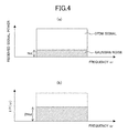
- FIGS. 4(a) and 4(b) are diagrams illustrating frequency characteristics of a received signal power and an interference power IP( ⁇ ) when Gaussian noise is superposed on an OFDM signal on a transmission channel.
- An average power of noise power superposed per carrier of an OFDM signal is represented by Nd.
- the four-symbol difference in channel response He ( ⁇ p) is obtained as described above, if a fluctuation over time in channel response is negligible, a linear sum of noise vectors is obtained as the differential vector ⁇ He ( ⁇ p).
- the noise vector linear sum has a power about two times larger than the superposed noise power on the transmission channel. Therefore, the average value of the interference power IP( ⁇ ) per carrier of an OFDM signal obtained by the interference calculation section 50 is about 2Nd as indicated in FIG. 4(b) . In other words, if correction is performed by multiplying a value of the interference power IP( ⁇ ) by 1/2, an approximate noise power can be appropriately detected.
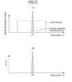
- FIGS. 5(a) and 5(b) are diagrams illustrating frequency characteristics of a received signal power and an interference power IP( ⁇ ), respectively, when there is interference with a specific carrier in the vicinity of a frequency ⁇ I.
- the specific carrier interference is a signal which does not have a correlation with the OFDM signal, an influence degree corresponding to a strength of the interference is converted into a power as in the case of FIG. 4, and the frequency position of the interference is appropriately detected as indicated in FIG. 5(b).
- the value of the interference power IP ( ⁇ ) per carrier of the OFDM signal which is obtained by the interference calculation section 50, indicates the degree of an influence of the fluctuation over time in channel response on a received signal.
- the carrier quality calculation section 60 of FIG. 1 has logarithmic calculation sections 62 and 64, and a difference calculation section 66.
- the logarithmic calculation sections 62 and 64 calculate logarithmic values LCP( ⁇ ) and LIP( ⁇ ) of the carrier power CP( ⁇ ) and the interference power IP( ⁇ ), respectively, and outputs the logarithmic values LCP( ⁇ ) and LIP( ⁇ ) to the difference calculation section 66.
- the difference calculation section 66 obtains a differential value between the output LCP ( ⁇ ) of the logarithmic calculation section 62 and the output LIP ( ⁇ ) of the logarithmic calculation section 64, and outputs the calculation result as a carrier quality value CSI ( ⁇ ) to the average calculation section 44.
- a value obtained by dividing the carrier power CP ( ⁇ ) by the interference power IP ( ⁇ ) may be obtained as the carrier quality value CSI ( ⁇ ) without conversion into a logarithm. In this case, a divider is required.
- the carrier quality value CSI ( ⁇ ) is assumed to be obtained from a difference between the logarithmic values of the carrier power CP ( ⁇ ) and the interference power IP ( ⁇ ).
- FIGS. 6(a) and 6(b) are diagrams illustrating a received signal power and a carrier quality value CSI ( ⁇ ) of each carrier of an OFDM signal when both multipath interference and noise interference are simultaneously present in a received signal. Since a noise power is superposed on each carrier as illustrated in FIG. 6(a), the carrier quality value CSI ( ⁇ ) of a carrier having a small received signal power is considerably small as illustrated in FIG. 6(b) .
- FIGS. 7(a) and 7(b) are diagram illustrating a received signal power and a carrier quality value CSI ( ⁇ ), respectively, when there is frequency selective interference with a specific carrier in the vicinity of the frequency ⁇ I. As illustrated in FIG. 7(b), the carrier quality value CSI ( ⁇ ) of an interfered carrier decreases.
- the value of the carrier power CP ( ⁇ ) obtained by the power calculation section 42 fluctuates for each symbol along with the fluctuation in channel response. Therefore, the carrier quality value CSI ( ⁇ ) for each carrier at each time (each symbol) can be appropriately calculated, depending on the power of a received signal.
- the carrier quality calculation section 60 obtains, as the carrier quality value CSI ( ⁇ ), either CP ( ⁇ )/ IP ( ⁇ ) or IP ( ⁇ )/ CP ( ⁇ ). There is no essential difference between these cases.
- the interpolation section 56 of the interference calculation section 50 does not need to perform the frequency-axis direction interpolation.
- the interpolation section 26 of the demodulation section 20 omits the frequency-axis direction interpolation when calculating a channel response for calculating the carrier power CP ( ⁇ ).
- FIG. 8 is a block diagram illustrating a configuration of a variation of the interference calculation section 50 of FIG. 1.
- the interference calculation section 150 of FIG. 8 comprises a distance detection section 154, a hard decision section 156, and an integration section 158.
- the interference calculation section 150 of FIG. 8 is used instead of the interference calculation section 50 in the OFDM reception apparatus of FIG. 1.
- the hard decision section 156 performs hard decision which decides a transmission signal point which is closest to a signal point on the i-q plane, for each carrier of the demodulated signal Xe ( ⁇ ) output from the division section 22, and outputs the decision result as a reference signal point to the distance calculation section 154.
- the distance calculation section 154 obtains, as a differential value, the square of a distance on the i-q plane between a signal point of each carrier of the demodulated signal Xe ( ⁇ ) output from the division section 22, and a reference signal point output from the hard decision section 156 corresponding thereto, and outputs the differential value to the integration section 158.
- the integration section 158 averages the differential value for each carrier in the time-axis direction, and outputs the resultant value (the variance value of the demodulated signal Xe ( ⁇ )) as an interference power IP ( ⁇ ) to the logarithmic calculation section 64.
- the interference calculation section 150 of FIG. 8 can also calculate, for each carrier, a value corresponding to the degree of an influence of various kinds of interference, such as noise interference occurring on a transmission channel and frequency selective interference (e.g., co-channel interference due to analog broadcasting, etc.), and the like.
- various kinds of interference such as noise interference occurring on a transmission channel and frequency selective interference (e.g., co-channel interference due to analog broadcasting, etc.), and the like.
- a method of calculating an interference power in the interference calculation section is not limited to the above-described method, and may be any method which can calculate the interference power IP( ⁇ ) as the degree of an influence of interference for each carrier.
- the OFDM reception apparatus of this embodiment calculates the carrier power CP( ⁇ ) based on the channel response He( ⁇ ) estimated from a pilot carrier, thereby making it possible to easily estimate a power of each carrier even under conditions of a transmission channel varying over time.
- the quality of each carrier is obtained as the carrier quality value CSI( ⁇ ) from the interference power IP( ⁇ ) and the carrier power CP( ⁇ ) of each carrier, and the average values on the frequency axis and the time axis of the carrier quality value CSI( ⁇ ) obtained for each carrier is assumed as the received signal quality value SQ of a received signal. Therefore, under various interference conditions, such as noise interference, mutipath, frequency selective interference with a specific carrier, a fluctuation in channel response occurring during moving, and the like, an influence thereof on a received signal can be estimated with high precision using a simple circuit configuration without correction with respect to each cause, and the received signal quality value SQ of a received signal on which the influence is reflected can be detected.
- the direction and position of an antenna can be appropriately set.
- an OFDM reception apparatus When an OFDM signal is received and demodulated, an amount of noise superposed on the received signal may be detected and utilized in a control of a gain of an output signal of a tuner.
- an OFDM reception apparatus will be described in which a power value of noise superposed on a received signal is detected.
- FIG. 9 is a block diagram illustrating a configuration of an OFDM reception apparatus according to a second embodiment of the present invention.
- the OFDM reception apparatus detects a noise power based on a channel response of a carrier transmitting a pilot signal.
- the OFDM reception apparatus of FIG. 9 comprises a tuner 12, an A/D conversion section 13, an AGC control section 214 (gain control section), a quadrature demodulation section 16, an FFT section 18, a demodulation section 20, a soft decision section 32, an error correction section 34, a source decoding section 36, and a noise power calculation section 70.
- FIG. 9 the same components as those of FIG. 1 are indicated with the same reference numerals and will not be described in detail.
- the AGC control section 214 receives a digitized IF OFDM signal from the A/D conversion section 13.
- the AGC control section 214 generates an AGC control signal for controlling a gain of the received signal, based on not only an average level of the received signal but also a noise power NP obtained in the noise power calculation section 70, so that an amplitude of the received signal goes to a predetermined level, and outputs the AGC control signal to the tuner 12.
- the noise power calculation section 70 comprises a difference calculation section 52, a power calculation section 54, and an average calculation section 76.
- the difference calculation section 52 and the power calculation section 54 are similar to those which have been described with reference to FIG. 1.
- the noise power calculation section 70 detects a power of noise superposed on the received signal, based on a channel response He( ⁇ p) with respect to a pilot carrier transmitting an SP signal.
- the average calculation section 76 averages an interference power IP( ⁇ p) with respect to a pilot carrier obtained in the power calculation section 54 in the frequency-axis direction or in both the frequency-axis direction and the time-axis direction, and outputs the result as a noise power NP superposed on the received OFDM signal.
- the interference power IP ( ⁇ p) with respect to the pilot carrier indicates interference superposed on the pilot signal, i.e., a noise power, as described in the first embodiment.
- the average calculation section 76 outputs the noise power NP to the AGC control section 214.
- the tuner 12 when converting an RF signal into an IF signal, uses a BPF (Band Pass Filter) to perform band limitation so as to remove an unnecessary band signal.
- BPF Band Pass Filter
- a signal is passed through the BPF after reducing the gain of the RF signal, and the gain of a signal after conversion into the IF signal is increased, thereby making it possible to suppress the adjacent channel signal from being mixed into the OFDM demodulation section.
- the AGC control section 214 outputs the AGC control signal so that the gain of the IF signal becomes larger than the gain of the RF signal in the tuner 12.
- the AGC control section 214 outputs the AGC control signal so that the gain of the IF signal becomes smaller than the gain of the RF signal in the tuner 12.
- the linear sum of noise vectors is obtained as a differential vector ⁇ He( ⁇ p) and the power is about two times larger than the noise power superposed on the transmission channel if a fluctuation over time in channel response is negligible. Therefore, by performing correction by multiplying the calculation result of the power calculation section 54 or the calculation result of the average calculation section 76 by 1/2, an approximate power of the noise interference can be appropriately detected.
- the noise power calculation section 70 since the power of the four-symbol difference of an SP signal is used as a noise power, even if there is multipath interference, a noise power superposed on a received signal can be detected without an influence of the multipath interference.
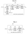
- FIG. 10 is a block diagram illustrating a configuration of a variation of the noise power calculation section 70 of FIG. 9.
- the noise power calculation section 270 of FIG. 10 comprises difference calculation sections 271, 272 and 273, a power calculation section 274, and an average calculation section 276.
- the difference calculation section 271 receives the channel responses He( ⁇ p) with respect to a pilot carrier obtained in the channel response calculation section 24, calculates a differential value ⁇ He1( ⁇ p) between a latest channel response and a channel response one cycle (4 symbols) before on the time axis with respect to the same pilot carrier, and outputs the differential value ⁇ He1( ⁇ p) to the difference calculation section 273.
- the difference calculation section 272 receives the channel responses He( ⁇ p) with respect to a pilot carrier obtained in the channel response calculation section 24, calculates a differential value ⁇ He2 ( ⁇ p) between a channel response four symbols before a latest channel response and a channel response one cycle before the channel response (i.e., a channel response eight symbols before the latest channel response) with respect to the same pilot carrier, and outputs the differential value ⁇ He2 ( ⁇ p) to the difference calculation section 273 .
- the difference calculation section 273 receives the differential value ⁇ He1( ⁇ p) and the differential value ⁇ He2 ( ⁇ p), calculates a differential value ⁇ He( ⁇ p) between ⁇ He1 ( ⁇ p) and ⁇ He2 ( ⁇ p), and outputs the differential value ⁇ He( ⁇ p) to the power calculation section 274 .
- the power calculation section 274 receives the differential value ⁇ He ( ⁇ p) obtained in the difference calculation section 273, obtains the sum of the squares of the i-axis component and the q-axis component of the differential value ⁇ He( ⁇ p) (complex vector), and outputs the sum, as an interference power IP( ⁇ p) with respect to a pilot carrier in which an SP signal is inserted, to the average calculation section 276.
- the average calculation section 276 averages the interference power IP( ⁇ p) with respect to the pilot carrier in the frequency-axis direction or in both the frequency-axis direction and the time-axis direction, and outputs the result, as a noise power NP superposed on the received OFDM signal, to the AGC control section 214.
- ⁇ He1 ( ⁇ p, s) is obtained as a four-symbol difference in channel response, i.e., a difference between He( ⁇ p, s) and He( ⁇ p, s+4).
- ⁇ He ⁇ 1 ( ⁇ p , s ) H ( ⁇ p , s + 4 ) + I ⁇ ( ⁇ p , s + 4 ) - ⁇ H ( ⁇ p , s ) + I ⁇ ( ⁇ p , s ) ⁇
- ⁇ He2 ( ⁇ p, s) is obtained as a difference between He ( ⁇ p, s+8) and He ( ⁇ p, s+4).
- ⁇ He ( ⁇ p, s) ⁇ ( H ( ⁇ p , s + 8 ) - H ( ⁇ p , s + 4 ) ) - ( H ( ⁇ p , s + 4 ) - H ( ⁇ p , s ) ) ⁇ + ⁇ ( I ⁇ ( ⁇ p , s + 8 ) - I ⁇ ( ⁇ p , s + 4 ) ) - ( I ⁇ ( ⁇ p , s + 4 ) - I ⁇ ( ⁇ p , s ) ) ⁇
- ⁇ He( ⁇ p, s) is obtained by : ⁇ ⁇ He ( ⁇ p , s ) ⁇ I ⁇ ( ⁇ p , s + 8 ) - I ⁇ ( ⁇ p , s + 4 ) ) - I ⁇ ( ⁇ p , s + 4 - I ⁇ ( ⁇ p , s ) )
- ⁇ He ( ⁇ p, s) has a high correlation with the magnitude of interference.
- the noise power detection precision can be improved as compared to that of the configuration of FIG. 9.
- the detection result of noise power can be obtained soon after start of a reception operation.
- the average calculation section 76 or 276 calculates an average value of the output of the power calculation section 54 or 274 by averaging in the time-axis direction as well as in the frequency-axis direction
- the detection result of noise power can be obtained with high precision as compared to when the average is calculated only in the frequency-axis direction. Therefore, an optimal average value calculation method may be selected, depending on the situation.
- FIG. 11 is a block diagram illustrating a configuration of another variation of the noise power calculation section 70 of FIG. 9.
- the noise power calculation section 370 of FIG. 11 comprises an IFFT section 372, a power calculation section 374, and a conditional average calculation section 376.
- the IFFT section 372 performs inverse Fourier transform (IFFT) on a channel response He( ⁇ p) with respect to a pilot carrier for each symbol to obtain an impulse response (time-domain signal), and outputs the impulse response to the power calculation section 374.
- the impulse response is also a complex signal.
- the power calculation section 374 calculates the sum of the squares of the i-axis component and the q-axis component of the input impulse response as a power of the impulse response, and outputs the power of the impulse response to the conditional average calculation section 376.
- FIG. 12 is a graph illustrating the power of the impulse response on a transmission channel obtained in the power calculation section 374 of FIG. 11.
- FIG. 12 illustrates an impulse response in the case where there are multipath interference and noise interference on the transmission channel.
- the impulse response on the transmission channel has peaks indicating a primary wave and a delayed wave, the primary wave and the delayed wave each have a locally concentrated power, and noise components are distributed at substantially a constant level in a floor portion irrespective of time.
- the conditional average calculation section 376 assumes power values lower than or equal to a predetermined threshold value as illustrated in FIG. 12 to be noise, averages these power values over predetermined symbols, and outputs the resultant average value as a noise power NP.
- the threshold value may be either a fixed value or a value having a predetermined ratio with respect to the peak value indicating the primary wave which is an OFDM signal component. Note that the threshold value is set to be substantially smaller than the levels of the primary wave and the delayed wave of a received OFDM signal.
- the channel response He( ⁇ p) may be multiplied by an appropriate window function on the frequency axis.
- the waveform of the OFDM signal component has a steep rise and fall, thereby making it possible to improve the noise power detection precision.
- the noise power calculation section 370 of FIG. 11 performs IFFT on a channel response He( ⁇ p) with respect to a pilot carrier, the channel response He( ⁇ p) being obtained from a received signal on which noise is superposed, to obtain an impulse response for each symbol, and detects a noise power based on components having values lower than or equal to the predetermined threshold value. Therefore, there is a less influence of a fluctuation over time in channel response, so that the noise power detection precision can be improved as compared to the noise power calculation section 70 of FIG. 9.
- FIG. 13 is a block diagram illustrating a configuration of still another variation of the noise power calculation section 70 of FIG. 9.
- the noise power calculation section 470 of FIG. 13 comprises noise power candidate calculation sections 80 and 380, and a minimum value selection section 478.
- the noise power candidate calculation sections 80 and 380 have configurations similar to that of the noise power calculation section 70 of FIG. 9 and that of the noise power calculation section 370 of FIG. 11, respectively.
- the noise power candidate calculation section 80 obtains a noise power N1 based on a four-symbol difference in channel response He ( ⁇ p) with respect to a pilot carrier, and outputs the noise power N1 to the minimum value selection section 478.
- the noise power candidate calculation section 380 obtains a noise power N2 based on an impulse response of the channel response He( ⁇ p) with respect to the pilot carrier, and outputs the noise power N2 to the minimum value selection section 478.
- the minimum value selection section 478 selects and outputs the smaller of the noise powers N1 and N2, as a noise power NP.
- the noise power candidate calculation section 80 tries to detect a noise power based on a power of difference in channel response.
- the result of difference calculation includes a fluctuation in channel response in addition to a noise component, and therefore, there is the possibility that the noise power N1 thus calculated has a value which is larger than an actual noise power of the transmission channel.
- the noise power candidate calculation section 380 tries to detect a noise power based on a power of an impulse response on a transmission channel.
- the delayed wave components having a small power may be determined to be noise, depending on the threshold value for distinguishing an OFDM signal from noise, and the calculated noise power N2 has a value larger than that of an actual noise power of the transmission channel.
- the values of the noise powers N1 and N2 calculated by the noise power candidate calculation sections 80 and 380, respectively may be larger than an actual noise power value, depending on conditions of a transmission channel. Nevertheless, since the noise powers N1 and N2 are obtained in different ways, an error with respect to the actual noise power value can be reduced to the extent possible by selecting the smaller of the noise powers N1 and N2. Therefore, according to the noise power calculation section 470 of FIG. 13, it is possible to improve the noise power detection precision with a less influence of a fluctuation over time in channel response as compared to the noise power calculation section 70 of FIG. 9.
- time-axis direction interpolation may be performed (i.e., a channel response is obtained every three carriers on the frequency axis), and thereafter, an impulse response may be obtained for each symbol by IFFT. In this case, an influence of aliasing on an impulse response can be reduced.
- the channel response may be multiplied by an appropriate window function on the frequency axis, and thereafter, an impulse response may be obtained for each symbol by IFFT.
- the waveform of the OFDM signal component has a steep rise and fall, thereby making it possible to improve the noise power detection precision.
- the reliability of each demodulated carrier may be estimated and the resultant information may be used to perform soft decision (demapping) with respect to the demodulated signal.
- soft decision demapping
- frequency selective interference such as multipath interference and specific-carrier interference or the like
- the position of a carrier affected by the interference and the degree of an influence of the interference are approximately detected as the reliability of the carrier, and based on the information, soft decision is performed with respect to the demodulated signal, thereby significantly improving error correction capability under an interference environment.
- an OFDM reception apparatus having a simple circuit configuration will be described in which the reliability of each carrier is obtained as a carrier quality value described below and the resultant value is used to perform soft decision even under various interference conditions, such as noise interference, multipath, frequency selective interference with a specific carrier, interference occurring during moving, and the like.
- FIG. 14 is a block diagram illustrating an exemplary configuration of an OFDM reception apparatus according to a third embodiment of the present invention.
- the OFDM reception apparatus of FIG. 14 is different from the OFDM reception apparatus of FIG. 1 in that the OFDM reception apparatus of FIG. 14 comprises a soft decision section 532 instead of the soft decision section 32, and does not comprise the average calculation section 44.
- the carrier quality calculation section 60 of FIG. 14 calculates the logarithmic values of the carrier power CP( ⁇ ) and the interference power IP( ⁇ ) as LCP( ⁇ ) and LIP( ⁇ ), obtains a differential value between LCP( ⁇ ) and LIP( ⁇ ), and outputs the calculation result as a carrier quality value CSI( ⁇ ) to the soft decision section 532.
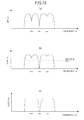
- FIGS. 15(a) and 15(b) are diagrams illustrating frequency characteristics of the carrier powers CP( ⁇ ) and LCP ( ⁇ ), respectively, when there is multipath interference.
- FIG. 15(a) there are drops of the carrier power CP( ⁇ ) in the vicinity of frequencies ⁇ a, ⁇ b and ⁇ c due to the multipath interference, and the drops have different magnitudes.
- FIG. 15(b) regarding the magnitudes (logarithmic values) of the drops of the carrier power LCP ( ⁇ ), whereas the largest drop at the vicinity of the frequency ⁇ b is clearer compared to FIG. 15(a), the smaller drops at the vicinity of the frequencies ⁇ a and ⁇ c are unclear compared to FIG. 15(a).
- the carrier power LCP( ⁇ ) logarithmic value
- the carrier power CP( ⁇ ) can be used to more correctly estimate an influence of the interference on a carrier having a relatively large magnitude of drop which is a dominant factor for a deterioration in reception performance, as compared to the carrier power CP( ⁇ ).
- FIGS. 16(a) and 16(b) are diagrams illustrating frequency characteristics of the interference powers IP( ⁇ ) and LIP ( ⁇ ), respectively, when there is analog co-channel interference.
- FIG. 16(a) it is assumed that there are peaks of the interference power IP( ⁇ ) in the vicinity of frequencies ⁇ a, ⁇ b and ⁇ c due to the analog co-channel interference.
- the interference power LIP( ⁇ ) (logarithmic value) clarifies the presence of small peaks which are difficult to recognize in FIG. 16(a), so that differences between these small peaks and the peaks in the vicinity of the frequencies ⁇ a, ⁇ b and ⁇ c, which seem to be large in FIG. 16(a), seem to be reduced.
- the interference power LIP( ⁇ ) logarithmic value
- the interference power IP( ⁇ ) can be used to more correctly estimate an influence of the interference on a carrier having a relatively small interference power, as compared to the interference power IP( ⁇ ).
- the difference calculation section 66 obtains a differential value between the carrier power LCP( ⁇ ) and the interference power LIP( ⁇ ) and outputs the differential value as a carrier quality value CSI( ⁇ ). Therefore, when there is multipath interference, a quality value of a carrier particularly significantly affected by the interference can be more clearly calculated. Also, when there is specific-carrier interference, such as analog co-channel interference or the like, a quality value of a carrier affected by the interference can be more clearly calculated.
- the soft decision section 532 performs soft decision with respect to the demodulated signal Xe( ⁇ ) output from the demodulation section 20, for each carrier, based on the carrier quality value CSI( ⁇ ) obtained from the carrier quality calculation section 60, to calculate soft decision metric data, and outputs the soft decision metric data to the error correction section 34.
- the soft decision section 532 calculates a value (likelihood) indicating a most "zeroness” or "oneness”, as the soft decision metric data, with respect to a carrier having considerably high reliability, and conversely, calculates a value indicating an intermediate value between "0" and "1", as the soft decision metric data, with respect to a carrier having considerably low reliability, and for other carriers, calculates a value, depending on a distance between a received signal point and an ideal signal point, and a value of the carrier quality value CSI( ⁇ ).
- the OFDM reception apparatus of FIG. 14 lowers the likelihood of "zeroness” and “oneness” of the metric data for a carrier affected by frequency selective interference, to reduce contribution to error correction, thereby making it possible to improve an effect of error correction with respect to the whole received signal.
- FIG. 17 is a block diagram illustrating a configuration of a variation of the carrier quality calculation section 60 of FIG. 14.
- the carrier quality calculation section 560 of FIG. 17 has logarithmic calculation sections 62 and 64, clip sections 563 and 565, and a difference calculation section 566.
- the logarithmic calculation sections 62 and 64 calculate the logarithmic values of the carrier power CP( ⁇ ) and the interference power IP( ⁇ ) as LCP( ⁇ ) and LIP ( ⁇ ), respectively, and outputs the logarithmic values to the clip sections 563 and 565.
- the clip section 563 subtracts a predetermined clip value from the carrier power LCP( ⁇ ) (logarithmic value), and outputs 0 when the subtraction result is positive, and outputs the subtraction result when the subtraction result is negative (clip process), and outputs the clipped carrier power CLCP( ⁇ ) to the difference calculation section 566.
- the clip section 565 subtracts a predetermined clip value from the interference power LIP( ⁇ ) (logarithmic value), and outputs 0 when the subtraction result is negative, and outputs the subtraction result when the subtraction result is positive (clip process), and outputs the clipped interference power CLIP( ⁇ ) to the difference calculation section 566.
- the difference calculation section 566 obtains a differential value between the output of the clip section 563 and the output of the clip section 565, and outputs the calculation result as a carrier quality value CSI( ⁇ ) to the soft decision section 532.
- FIG. 15(c) is a diagram illustrating frequency characteristics of the clipped carrier power CLCP( ⁇ ) when there is multipath interference.
- the clip section 563 clips the carrier power LCP( ⁇ ) of FIG. 15(b), where the clip value is THC.
- FIG. 15(c) a state of the resultant carrier power CLCP( ⁇ ) in the vicinity of the frequency ⁇ b where there is a largest drop is more clearly indicated than in FIG. 15(b), and other drops are substantially not indicated.
- the clipped carrier power CLCP( ⁇ ) can be used to more correctly estimate an influence of interference with respect to a carrier having a large drop which is a dominant factor for a deterioration in reception performance, as compared to the carrier power CP( ⁇ ) or LCP ( ⁇ ).
- FIG. 16(c) is a diagram illustrating frequency characteristics of the clipped interference power CLIP( ⁇ ) when there is analog co-channel interference.
- the clip section 565 clips the interference power LIP( ⁇ ) of FIG. 16(b), where the clip value is THI.
- the resultant interference power CLIP( ⁇ ) only peaks having levels larger than or equal to a predetermined level can be recognized, and other peaks are substantially not indicated.
- the clipped interference power CLIP ( ⁇ ) can be used to more correctly estimate an influence of interference with respect to a carrier having a relatively large interference power larger than or equal to the predetermined level, which is a more dominant factor for a deterioration in reception performance than a carrier having a considerably small interference power which has a less influence on reception performance, as compared to the carrier power CI ( ⁇ ) or LCI ( ⁇ ).
- the difference calculation section 566 calculates a differential value ( CLCP ( ⁇ ) - CLIP( ⁇ )) between the clipped carrier power CLCP( ⁇ ) and the interference power CLIP( ⁇ ), and outputs the differential value as a carrier quality value CSI ( ⁇ ). Therefore, when there is multipath interference, the quality value of a carrier particularly significantly affected by the interference can be more appropriately calculated. When there is specific-carrier interference (e.g., analog co-channel interference, etc.) or the like, the quality value of a carrier affected by the interference can be more appropriately calculated.
- specific-carrier interference e.g., analog co-channel interference, etc.
- FIG. 18 is a block diagram illustrating a configuration of a variation of the interference calculation section 50 of FIG. 14.
- the interference calculation section 650 of FIG. 18 comprises difference calculation sections 271, 272 and 273, a power calculation section 274, and an interpolation section 656.
- the difference calculation sections 271 to 273 and the power calculation section 274 are similar to those described with reference to FIG. 10 and will not be described.
- the interpolation section 656 interpolates interference power IP( ⁇ p) with respect to a pilot carrier obtained in the power calculation section 274 in the time-axis direction and the frequency-axis direction to obtain an interference power IP ( ⁇ ), and outputs the interference power IP( ⁇ ).
- the detection precision of the interference power IP( ⁇ ) is improved as compared to the configuration of FIG. 14.
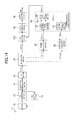
- FIG. 19 is a block diagram illustrating a configuration of a variation of the OFDM reception apparatus of the third embodiment of the present invention.
- the OFDM reception apparatus of FIG. 19 is different from the OFDM reception apparatus of FIG. 14 in that the OFDM reception apparatus of FIG. 19 further comprises the average calculation section 44 of FIG. 1.
- the average calculation section 44 uses the carrier quality value CSI( ⁇ ) obtained for soft decision, so that neither of the interference calculation section 50 and the carrier quality calculation section 60 is further required for obtaining the received signal quality value SQ . Therefore, when the received signal quality value SQ is to be obtained, in addition to performing soft decision in view of the degree of an influence of interference, an increase in circuit scale can be prevented.
- FIG. 20 is a block diagram illustrating a configuration of another variation of the OFDM reception apparatus of the third embodiment of the present invention.
- the OFDM reception apparatus of FIG. 20 is different from the OFDM reception apparatus of FIG. 14 in that the OFDM reception apparatus of FIG. 20 comprises a carrier quality calculation section 660 and a soft decision section 632 instead of the carrier quality calculation section 60 and the soft decision section 532, respectively.
- the carrier quality calculation section 660 of FIG. 20 is different from the carrier quality calculation section 560 of FIG. 17 in that the difference calculation section 565 is removed from the carrier quality calculation section 560.
- the carrier quality calculation section 660 outputs the clipped carrier power CLCP( ⁇ ) and the clipped interference power CLCP( ⁇ ) which are obtained from the clip sections 563 and 565, respectively, to the soft decision section 632.
- the soft decision section 632 performs soft decision with respect to the demodulated signal Xe( ⁇ ) output from the demodulation section 20 for each carrier, based on both or either of the clipped carrier power CLCP( ⁇ ) and the clipped interference power CLCP ( ⁇ ), to calculate soft decision metric data, and outputs the soft decision metric data to the error correction section 34.
- the carrier quality calculation section 660 outputs the carrier power CLCP( ⁇ ) and the interference power CLIP( ⁇ ) separately, and the soft decision section 632 tries to perform soft decision using both or either of the carrier power CLCP( ⁇ ) and the interference power CLIP( ⁇ ).
- the soft decision section 632 a likelihood can be calculated while assigning different weights to the carrier power CLCP( ⁇ ) and the interference power CLIP( ⁇ ).
- the OFDM reception apparatus of this embodiment performs soft decision with respect to each carrier of a received OFDM signal from a carrier power and an interference power indicating the degree of an influence of interference, based on a quality value obtained for each carrier. Therefore, the degree of an influence of interference on each carrier can be estimated with high precision, and the information can be used to perform effective soft decision, thereby making it possible to improve demodulation and error correction capabilities.
- the OFDM reception apparatus of FIG. 14 may comprise the interference calculation section 150 of FIG. 8 instead of the interference calculation section 50.
- the OFDM reception apparatus of FIG. 1 may comprise the interference calculation section 650 of FIG. 18 instead of the interference calculation section 50.
- a simple circuit configuration can be used to detect a signal quality value of a received signal on which an influence of interference on an OFDM signal is reflected, and a value of a noise power with high precision even under various interference conditions. Also, the reliability of each carrier can be appropriately calculated, thereby making it possible to improve demodulation and error correction capabilities. Therefore, the present invention is useful for an OFDM reception apparatus and the like.
Landscapes
- Engineering & Computer Science (AREA)
- Computer Networks & Wireless Communication (AREA)
- Signal Processing (AREA)
- Quality & Reliability (AREA)
- Physics & Mathematics (AREA)
- Mathematical Physics (AREA)
- General Physics & Mathematics (AREA)
- Discrete Mathematics (AREA)
- Electromagnetism (AREA)
- Noise Elimination (AREA)
- Radio Transmission System (AREA)
- Circuits Of Receivers In General (AREA)
- Monitoring And Testing Of Transmission In General (AREA)
Applications Claiming Priority (2)
| Application Number | Priority Date | Filing Date | Title |
|---|---|---|---|
| JP2004138194 | 2004-05-07 | ||
| PCT/JP2005/008430 WO2005109711A1 (fr) | 2004-05-07 | 2005-05-09 | Appareil recepteur ofdm et procede de reception ofdm |
Publications (1)
| Publication Number | Publication Date |
|---|---|
| EP1742401A1 true EP1742401A1 (fr) | 2007-01-10 |
Family
ID=35320542
Family Applications (1)
| Application Number | Title | Priority Date | Filing Date |
|---|---|---|---|
| EP20050737200 Withdrawn EP1742401A1 (fr) | 2004-05-07 | 2005-05-09 | Appareil recepteur ofdm et procede de reception ofdm |
Country Status (7)
| Country | Link |
|---|---|
| US (1) | US7684503B2 (fr) |
| EP (1) | EP1742401A1 (fr) |
| JP (2) | JPWO2005109711A1 (fr) |
| KR (1) | KR100816609B1 (fr) |
| CN (1) | CN1954528A (fr) |
| TW (1) | TW200603191A (fr) |
| WO (1) | WO2005109711A1 (fr) |
Cited By (5)
| Publication number | Priority date | Publication date | Assignee | Title |
|---|---|---|---|---|
| EP2180619A1 (fr) * | 2007-07-31 | 2010-04-28 | Nec Corporation | Procédé d'estimation de canal |
| US8107909B2 (en) | 2007-09-28 | 2012-01-31 | Kyocera Corporation | Reception device, radio communication terminal, radio base station, and reception method |
| US8355454B2 (en) | 2006-08-03 | 2013-01-15 | Panasonic Corporation | Reception device, reception method and integrated circuit |
| US8553749B2 (en) | 2007-06-25 | 2013-10-08 | Aker Subsea Limited | Signal encoding for frequency division multiplexing on transmission lines |
| EP2194666A4 (fr) * | 2007-09-28 | 2016-06-01 | Kyocera Corp | Dispositif de radiocommunication et procédé d'estimation de la qualité de réception |
Families Citing this family (36)
| Publication number | Priority date | Publication date | Assignee | Title |
|---|---|---|---|---|
| US8331216B2 (en) * | 2005-08-09 | 2012-12-11 | Qualcomm Incorporated | Channel and interference estimation in single-carrier and multi-carrier frequency division multiple access systems |
| JP4659840B2 (ja) * | 2005-12-28 | 2011-03-30 | 富士通株式会社 | 通信装置及びチャネル推定方法 |
| US7564912B2 (en) * | 2006-02-15 | 2009-07-21 | Mediatek Inc. | Method and apparatus for channel state information generation in a DVB-T receiver |
| JP4802763B2 (ja) * | 2006-02-28 | 2011-10-26 | カシオ計算機株式会社 | Ofdm信号受信装置、ofdm信号受信方法及び地上波デジタル放送受信装置 |
| JP2007295257A (ja) * | 2006-04-25 | 2007-11-08 | Mitsubishi Electric Corp | 雑音電力算出手段およびs/n推定手段 |
| US8045927B2 (en) * | 2006-04-27 | 2011-10-25 | Nokia Corporation | Signal detection in multicarrier communication system |
| US7856005B2 (en) * | 2006-06-06 | 2010-12-21 | Himax Technologies Limited | Impulsive noise suppression scheme in orthogonal frequency division multiplexing |
| US20070297497A1 (en) * | 2006-06-21 | 2007-12-27 | Seibert Cristina A | Apparatus And Method For Interference Cancellation |
| EP2045940B1 (fr) * | 2006-07-25 | 2017-10-11 | Fujitsu Limited | Procédé d'estimation de bruit dans un système de communication à plusieurs porteuses et dispositif d'estimation de bruit de brouillage |
| KR101169415B1 (ko) * | 2006-08-03 | 2012-07-27 | 삼성전자주식회사 | 광대역 무선접속 통신시스템에서 자동 이득 제어 장치 및방법 |
| JP4814759B2 (ja) * | 2006-11-09 | 2011-11-16 | 三菱電機株式会社 | 回線品質測定装置、基地局および端末 |
| JP4816424B2 (ja) * | 2006-11-21 | 2011-11-16 | 株式会社デンソー | 受信方式,受信装置,プログラム |
| KR100917708B1 (ko) * | 2007-06-29 | 2009-09-21 | 한국전자통신연구원 | 데이터 전송 장치 및 방법, 데이터 수신 장치 및 방법 |
| US8290060B2 (en) * | 2007-08-21 | 2012-10-16 | Limberg Allen Leroy | Staggercasting of DTV signals that employ concatenated convolutional coding |
| US7864836B1 (en) * | 2007-10-31 | 2011-01-04 | Samsung Electronics Co., Ltd. | Adaptive orthogonal frequency division multiplexing (OFDM) equalizers, OFDM receivers including the same, and methods thereof |
| US20090268678A1 (en) * | 2008-04-24 | 2009-10-29 | Fujitsu Limited | Method and apparatus for automatic gain control in a mobile orthogonal frequency division multiple access (ofdma) network |
| JP4870730B2 (ja) * | 2008-07-30 | 2012-02-08 | 京セラ株式会社 | 無線基地局 |
| JP4881939B2 (ja) * | 2008-12-19 | 2012-02-22 | 日本電信電話株式会社 | マルチキャリア無線通信システム及びマルチキャリア無線通信方法 |
| JP4857330B2 (ja) * | 2008-12-19 | 2012-01-18 | 日本電信電話株式会社 | マルチキャリア無線通信システム及びマルチキャリア無線通信方法 |
| EP2387840B1 (fr) * | 2009-01-16 | 2013-06-05 | Abilis Systems Sarl | Évaluation interpolée des canaux pour systèmes ofdm mobiles |
| GB2467803B (en) * | 2009-04-03 | 2011-01-19 | Cambridge Silicon Radio Ltd | Treating carrier-specific interference |
| US20100254496A1 (en) * | 2009-04-06 | 2010-10-07 | Guo-Hau Gau | Noise power estimation method and device thereof |
| JP2010278550A (ja) * | 2009-05-26 | 2010-12-09 | Toshiba Corp | Ofdm受信装置 |
| KR101313271B1 (ko) * | 2009-12-18 | 2013-09-30 | 한국전자통신연구원 | 이웃 셀 수신신호 측정 방법 및 그 장치 |
| JP2011199421A (ja) * | 2010-03-17 | 2011-10-06 | Kyocera Corp | 通信装置および受信電力測定方法 |
| EP2395722A1 (fr) * | 2010-06-11 | 2011-12-14 | Intel Mobile Communications Technology Dresden GmbH | Récepteur de bande de base LTE et procédé de fonctionement |
| CN102404257B (zh) * | 2010-09-17 | 2014-07-16 | 中兴通讯股份有限公司 | Mimo-ofdm系统中的窄带干扰检测方法及装置 |
| US8823806B2 (en) * | 2011-02-18 | 2014-09-02 | Wi-Lan, Inc. | Method and apparatus for television band pilot sensing |
| JP5710534B2 (ja) * | 2012-03-27 | 2015-04-30 | 株式会社東芝 | 周波数領域等化装置及び受信装置 |
| JP6073189B2 (ja) * | 2013-05-31 | 2017-02-01 | 株式会社日立国際電気 | Ofdm受信装置 |
| CA2935464C (fr) * | 2013-12-31 | 2019-05-28 | Huawei Technologies Co., Ltd. | Methode d'acquisition d'information de canal, appareil et systeme |
| JP6209990B2 (ja) * | 2014-02-27 | 2017-10-11 | 富士通株式会社 | 受信装置 |
| KR101432233B1 (ko) * | 2014-03-31 | 2014-08-21 | (주)아이앤씨테크놀로지 | 무선랜 시스템의 다중채널 전송장치 |
| DE102014111735A1 (de) * | 2014-08-18 | 2016-02-18 | Intel IP Corporation | Funkkommunikationseinrichtungen und Verfahren zum Steuern einer Funkkommunikationseinrichtung |
| TWI575901B (zh) * | 2015-06-17 | 2017-03-21 | 晨星半導體股份有限公司 | 通道效應消除裝置及通道效應消除方法 |
| TWI627846B (zh) * | 2016-03-30 | 2018-06-21 | 晨星半導體股份有限公司 | 等化增強模組、解調變系統以及等化增強方法 |
Family Cites Families (24)
| Publication number | Priority date | Publication date | Assignee | Title |
|---|---|---|---|---|
| JP2517704B2 (ja) * | 1984-09-10 | 1996-07-24 | ソニー株式会社 | 音声信号受信装置 |
| JP3492418B2 (ja) * | 1994-06-23 | 2004-02-03 | シャープ株式会社 | 直接スペクトル拡散通信装置、その復調回路、オートゲインコントロール方法、及び直接スペクトル拡散通信装置の基準値設定方法 |
| US5784410A (en) * | 1996-06-03 | 1998-07-21 | Matsushita Electric Industrial Co., Ltd. | Reception automatic gain control system and method |
| US5878089A (en) * | 1997-02-21 | 1999-03-02 | Usa Digital Radio Partners, L.P. | Coherent signal detector for AM-compatible digital audio broadcast waveform recovery |
| JP2954570B1 (ja) | 1998-06-02 | 1999-09-27 | 株式会社次世代デジタルテレビジョン放送システム研究所 | 周波数選択性妨害訂正装置 |
| JP3531510B2 (ja) * | 1998-12-16 | 2004-05-31 | 日本ビクター株式会社 | Agc装置 |
| JP2000224140A (ja) * | 1999-02-03 | 2000-08-11 | Matsushita Electric Ind Co Ltd | 直交周波数分割多重装置 |
| JP3710658B2 (ja) * | 1999-09-29 | 2005-10-26 | 株式会社東芝 | 自動利得制御回路および受信機 |
| JP3455773B2 (ja) * | 1999-12-20 | 2003-10-14 | 独立行政法人通信総合研究所 | 直交周波数分割多重無線伝送システムの搬送波電力対ノイズ電力密度比を測定する測定システム、送信装置、測定装置、送信方法、測定方法、および、情報記録媒体 |
| JP3872950B2 (ja) | 2000-10-05 | 2007-01-24 | 株式会社東芝 | 周波数分割多重伝送信号受信装置 |
| JP3776716B2 (ja) | 2000-11-17 | 2006-05-17 | 株式会社東芝 | 直交周波数分割多重伝送信号受信装置 |
| JP3960511B2 (ja) * | 2001-05-07 | 2007-08-15 | 日本放送協会 | Ofdm信号解析装置 |
| JP3798264B2 (ja) * | 2001-06-07 | 2006-07-19 | 日本放送協会 | 等価cn比とビット誤り率の測定装置及び方法 |
| US7190748B2 (en) * | 2001-08-17 | 2007-03-13 | Dsp Group Inc. | Digital front-end for wireless communication system |
| US20030162518A1 (en) * | 2002-02-22 | 2003-08-28 | Baldwin Keith R. | Rapid acquisition and tracking system for a wireless packet-based communication device |
| JP4299148B2 (ja) * | 2002-04-15 | 2009-07-22 | パナソニック株式会社 | 受信装置および受信方法 |
| JP3849122B2 (ja) * | 2002-05-23 | 2006-11-22 | 富士通株式会社 | 直交周波数多重−符号分割多元接続伝送方式の受信装置 |
| JP4043287B2 (ja) * | 2002-05-24 | 2008-02-06 | 三菱電機株式会社 | 無線通信システム、通信装置および受信品質測定方法 |
| JP2004134831A (ja) * | 2002-10-08 | 2004-04-30 | Matsushita Electric Ind Co Ltd | 自動利得制御回路 |
| EP1408625A3 (fr) * | 2002-10-11 | 2006-09-06 | Matsushita Electric Industrial Co., Ltd. | Récepteur en diversité et procédé de réception en diversité de signaux FDM |
| JP2004135120A (ja) * | 2002-10-11 | 2004-04-30 | Matsushita Electric Ind Co Ltd | ダイバーシティ受信装置及びダイバーシティ受信方法 |
| US7295517B2 (en) * | 2002-11-27 | 2007-11-13 | Texas Instruments Incorporated | Method and apparatus for channel quality metric generation within a packet-based multicarrier modulation communication system |
| CN1802831B (zh) * | 2003-03-28 | 2010-05-26 | 英特尔公司 | 用于ofdm信号的自适应相位补偿的方法和装置 |
| US7388847B2 (en) * | 2003-08-18 | 2008-06-17 | Nortel Networks Limited | Channel quality indicator for OFDM |
-
2005
- 2005-05-09 EP EP20050737200 patent/EP1742401A1/fr not_active Withdrawn
- 2005-05-09 US US11/579,810 patent/US7684503B2/en not_active Expired - Fee Related
- 2005-05-09 TW TW094114952A patent/TW200603191A/zh unknown
- 2005-05-09 WO PCT/JP2005/008430 patent/WO2005109711A1/fr not_active Application Discontinuation
- 2005-05-09 KR KR20067018854A patent/KR100816609B1/ko not_active IP Right Cessation
- 2005-05-09 CN CNA2005800129064A patent/CN1954528A/zh active Pending
- 2005-05-09 JP JP2006513013A patent/JPWO2005109711A1/ja not_active Ceased
-
2010
- 2010-09-15 JP JP2010207078A patent/JP4749501B2/ja not_active Expired - Fee Related
Non-Patent Citations (1)
| Title |
|---|
| See references of WO2005109711A1 * |
Cited By (6)
| Publication number | Priority date | Publication date | Assignee | Title |
|---|---|---|---|---|
| US8355454B2 (en) | 2006-08-03 | 2013-01-15 | Panasonic Corporation | Reception device, reception method and integrated circuit |
| US8553749B2 (en) | 2007-06-25 | 2013-10-08 | Aker Subsea Limited | Signal encoding for frequency division multiplexing on transmission lines |
| EP2180619A1 (fr) * | 2007-07-31 | 2010-04-28 | Nec Corporation | Procédé d'estimation de canal |
| EP2180619A4 (fr) * | 2007-07-31 | 2014-11-05 | Nec Corp | Procédé d'estimation de canal |
| US8107909B2 (en) | 2007-09-28 | 2012-01-31 | Kyocera Corporation | Reception device, radio communication terminal, radio base station, and reception method |
| EP2194666A4 (fr) * | 2007-09-28 | 2016-06-01 | Kyocera Corp | Dispositif de radiocommunication et procédé d'estimation de la qualité de réception |
Also Published As
| Publication number | Publication date |
|---|---|
| KR100816609B1 (ko) | 2008-03-24 |
| CN1954528A (zh) | 2007-04-25 |
| WO2005109711A1 (fr) | 2005-11-17 |
| JP4749501B2 (ja) | 2011-08-17 |
| US20080260052A1 (en) | 2008-10-23 |
| KR20070004720A (ko) | 2007-01-09 |
| JPWO2005109711A1 (ja) | 2008-03-21 |
| TW200603191A (en) | 2006-01-16 |
| JP2011010363A (ja) | 2011-01-13 |
| US7684503B2 (en) | 2010-03-23 |
Similar Documents
| Publication | Publication Date | Title |
|---|---|---|
| US7684503B2 (en) | OFDM reception apparatus and OFDM reception method | |
| US7519122B2 (en) | OFDM reception apparatus and OFDM reception method | |
| JP4938679B2 (ja) | キャリア間干渉除去装置及びこれを用いた受信装置 | |
| JPWO2003088538A1 (ja) | 受信装置および受信方法 | |
| US8363539B2 (en) | OFDM receiver and OFDM receiving method | |
| JP3740468B2 (ja) | Ofdm受信装置及びデータ復調方法 | |
| US7751351B2 (en) | Disturbing signal detecting device for detecting a disturbing signal and OFDM receiver using the same | |
| EP1195960B1 (fr) | Démappage dans un récepteur multiporteuse | |
| US8155223B2 (en) | Receiving device, receiving method, and program | |
| JP5896795B2 (ja) | 等化装置、受信装置及び等化方法 | |
| US8428538B2 (en) | Channel estimator | |
| US9094273B2 (en) | Receiving apparatus and communication apparatus, and communication system | |
| JP4516489B2 (ja) | 受信装置 | |
| JP2008167116A (ja) | 受信装置および方法、並びにプログラム | |
| JP5319384B2 (ja) | 受信装置 | |
| US20110243280A1 (en) | Receiver and receiving method | |
| JP2007288450A (ja) | 復調装置及び方法 | |
| JP2005236666A (ja) | Ofdm復調装置 | |
| JP5599677B2 (ja) | ダイバシティ受信装置及びダイバシティ受信方法 | |
| JP2007258794A (ja) | Ofdm受信機における雑音低減方法及びその装置 | |
| JP2009290579A (ja) | Ofdm受信装置 | |
| JP2008187652A (ja) | 受信装置及び通信方法 |
Legal Events
| Date | Code | Title | Description |
|---|---|---|---|
| PUAI | Public reference made under article 153(3) epc to a published international application that has entered the european phase |
Free format text: ORIGINAL CODE: 0009012 |
|
| 17P | Request for examination filed |
Effective date: 20061108 |
|
| AK | Designated contracting states |
Kind code of ref document: A1 Designated state(s): DE FR GB NL |
|
| DAX | Request for extension of the european patent (deleted) | ||
| RBV | Designated contracting states (corrected) |
Designated state(s): DE FR GB NL |
|
| RAP1 | Party data changed (applicant data changed or rights of an application transferred) |
Owner name: PANASONIC CORPORATION |
|
| STAA | Information on the status of an ep patent application or granted ep patent |
Free format text: STATUS: THE APPLICATION HAS BEEN WITHDRAWN |
|
| 18W | Application withdrawn |
Effective date: 20100401 |