EP1741841A1 - Schachtoberteil - Google Patents
Schachtoberteil Download PDFInfo
- Publication number
- EP1741841A1 EP1741841A1 EP06012707A EP06012707A EP1741841A1 EP 1741841 A1 EP1741841 A1 EP 1741841A1 EP 06012707 A EP06012707 A EP 06012707A EP 06012707 A EP06012707 A EP 06012707A EP 1741841 A1 EP1741841 A1 EP 1741841A1
- Authority
- EP
- European Patent Office
- Prior art keywords
- shaft
- access part
- cone
- shaft top
- access
- Prior art date
- Legal status (The legal status is an assumption and is not a legal conclusion. Google has not performed a legal analysis and makes no representation as to the accuracy of the status listed.)
- Granted
Links
Images
Classifications
-
- E—FIXED CONSTRUCTIONS
- E02—HYDRAULIC ENGINEERING; FOUNDATIONS; SOIL SHIFTING
- E02D—FOUNDATIONS; EXCAVATIONS; EMBANKMENTS; UNDERGROUND OR UNDERWATER STRUCTURES
- E02D29/00—Independent underground or underwater structures; Retaining walls
- E02D29/12—Manhole shafts; Other inspection or access chambers; Accessories therefor
- E02D29/124—Shaft entirely made of synthetic material
-
- E—FIXED CONSTRUCTIONS
- E02—HYDRAULIC ENGINEERING; FOUNDATIONS; SOIL SHIFTING
- E02D—FOUNDATIONS; EXCAVATIONS; EMBANKMENTS; UNDERGROUND OR UNDERWATER STRUCTURES
- E02D29/00—Independent underground or underwater structures; Retaining walls
- E02D29/12—Manhole shafts; Other inspection or access chambers; Accessories therefor
-
- E—FIXED CONSTRUCTIONS
- E02—HYDRAULIC ENGINEERING; FOUNDATIONS; SOIL SHIFTING
- E02D—FOUNDATIONS; EXCAVATIONS; EMBANKMENTS; UNDERGROUND OR UNDERWATER STRUCTURES
- E02D29/00—Independent underground or underwater structures; Retaining walls
- E02D29/12—Manhole shafts; Other inspection or access chambers; Accessories therefor
- E02D29/121—Manhole shafts; Other inspection or access chambers; Accessories therefor characterised by the connection between shaft elements, e.g. of rings forming said shaft
Definitions
- the invention relates to a shaft top according to the preamble of claim 1.
- Such shaft tops are known from the prior art and practice. Due to the outwardly arched shape, such shaft tops usually have a good resistance to compressive forces exerted on the shaft top of the underground surrounding the shaft structure.
- a disadvantage of the known shaft top parts is that the region of the transition between the shaft cone and the access part is more easily deformed than the shaft cone or the access part.
- Another disadvantage of the known shaft tops is that their production costs are very high, for example in the rotation process, while in the case of shaft tops, which are produced by injection molding, vertical reinforcements for the removal of vertical loads missing.
- a generic shaft top is from the DE 697 11 377 T2 known.
- the disclosure relates to a shaft top with an access part and a shaft cone, which is connected to the access part and can be placed with a peripheral part opposite the access part on a manhole ring, wherein the shaft cone has a substantially outwardly arched basic shape.
- This shaft top is intended to overcome the disadvantages of the known prior art, especially in compressive stresses do not bend inwards. This is to be realized in that in the region of the transition from the access part to the shaft cone a substantially parallel to the plane in which the peripheral edge is located aligned reinforcing rib is provided on the outer surface of the shaft cone, which extends over the entire circumference of the shaft cone.
- a disadvantage of this shaft top is that when inspections by persons, for example in the context of inspections of existing pits no way it is safe to enter the shaft or to reach the shaft bottom. In this shaft top there are no possibilities to mount a climbing aid or a ladder safe to walk so that the inside of the shaft can be inspected. Another disadvantage is seen that the person gets in from above with his back to the center of the shaft and the light conditions in the shaft are very unfavorable, so that any existing climbing aids hardly stand out from the ground of the shaft and so there is a considerable security risk during inspections. Another disadvantage is seen in the fact that a possible inspection or inspection by means of climbing aids or ladders is only possible if they can be firmly anchored in the wall of the shaft top.
- the shaft top according to the invention is characterized in that at least one retaining element is arranged in the access part. It has been found that by the particular one-piece attachment of retaining elements in the access section a simple way is created to secure additional climbing aids or other required for a visit tools such as ladders safely and easily. Furthermore, it has been found to be advantageous that the retaining elements on the access part when opening a well filled and filled in the ground very easily by the inspection staff after opening the shaft top final lid can be reached, since these are arranged only at a small distance from the ground level.
- the holding element is advantageously approximately U-shaped and has an opening into which, for example, climbing aids can be introduced, but which can also be used, for example, to move objects determined by the staff accident-free down into the shaft.
- the holding elements of the upper part of the shaft according to the invention are arranged opposite each other in a further advantageous embodiment, for example, to introduce a tread, so that the inspection personnel can reach this next, positioned at a small distance from the ground level, tread accident-free to the next mounted in the shaft structure treads.
- this tread is easily removable at any time, so that even larger, for example, necessary for a cleaning of the shaft tools can be lowered through the opening of the access section into the shaft.
- shaft upper part according to the invention Another advantage of the shaft upper part according to the invention is seen in the fact that through the use of a thermoplastically processable material, in particular polypropylene, for the shaft top according to the invention a cost-effective production can be realized, at the same time high ring stiffness or impact resistance.
- a shaft top according to the invention is easy to inspect by a light coloration such as orange brown and has a very high chemical resistance by the use of a polypropylene material.
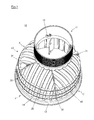
- Fig. 1 shows a shaft top 10 according to the invention for a shaft, not shown, with an access part 11 and a chute cone 12 which is connected to the access part 11 and with a connecting element 13 on the access part 11 opposite side of the shaft cone 12 to another shaft element, such as For example, a middle part or lower part is placed.
- the shaft cone 12 of the shaft top 10 has a substantially outwardly arched basic shape.
- the shaft top 10 according to the invention is designed such that the shaft cone 12 has at least three sections A, B, C, in which substantially mutually parallel stiffening elements 20 are arranged.
- the sections A, B, C of the shaft upper part 10 according to the invention can be separated from one another by at least one reinforcing element 30, which further improves the rigidity of the shaft upper part 10 according to the invention.
- the reinforcing element 30 advantageously connects the connecting element 13 to the access part 11.
- the shaft top 10 according to the invention has a reinforcing element 40, which is spaced from the connecting element 13 and which is arranged circumferentially on the shaft cone 12 in this embodiment. In this embodiment, three reinforcing elements 40 are arranged to achieve a required ring stiffness.
- the reinforcing elements 40 are integrally connected to the shaft cone 12.
- the stiffening elements 20 of the shaft upper part 10 according to the invention are formed in this embodiment as a bead or bead, which interrupt the inner surface of the shaft cone 12, so that the stiffening elements 20 are arranged approximately wave-shaped.
- the shaft top 10 according to the invention has on the reinforcing elements 30 on transport elements 31, which ensure both in the manufacture of the shaft top 10 as well as during transport or installation safety and reduce the risk of accidents.
- securing elements 32 are arranged on the reinforcing element, which are particularly suitable to a simple and secure manner a restrained connection with an underlying Shaft center part or manhole base to produce without a costly welding of the manhole components is necessary.
- the securing elements 32 during transport of the shaft top 10 of the invention provide additional security.
- In the region of the connecting element 13 of the upper shaft part 10 at least one marking element 14 is arranged, which ensures in particular during assembly of the upper shaft part 10 on a shaft structure for a quick alignment and secure installation.
- the shaft top 10 according to the invention has in its access part 11 at least one holding element 15, which is connected in this embodiment in one piece with this.
- this holding element 15 in the access part 11 a trouble-free and accident-free access to the shaft structure is possible, especially at high shaft tops or access openings.
- an additional, corrosion-resistant climbing or holding element can be introduced, in particular if two oppositely positioned holding elements 15 are arranged in the access part 11. This has the advantage that with it the original distance from the ground level to the first riser is reduced and thus a substantially safe boarding of the shaft structure is ensured via the shaft top 10.
- An additionally insertable riser element is due to the optimized geometry of the support member 15 simple, secure and fixed to the shaft top 10 connectable.
- access aids, closures or cleaning and inspection devices can be introduced into the holding elements 15 so that damage to the access part 11 or the shaft cone 12 of the shaft top 10 but also a costly installation of such aids are avoided.
Landscapes
- Engineering & Computer Science (AREA)
- Civil Engineering (AREA)
- Life Sciences & Earth Sciences (AREA)
- General Life Sciences & Earth Sciences (AREA)
- Mining & Mineral Resources (AREA)
- Paleontology (AREA)
- Environmental & Geological Engineering (AREA)
- General Engineering & Computer Science (AREA)
- Structural Engineering (AREA)
- Underground Structures, Protecting, Testing And Restoring Foundations (AREA)
- Sewage (AREA)
- Excavating Of Shafts Or Tunnels (AREA)
- Mechanically-Actuated Valves (AREA)
- Tents Or Canopies (AREA)
Abstract
Aufgabe der Erfindung ist, die Nachteile des bekannten Standes der Technik zu überwinden und ein Schachtoberteil aufzuzeigen, welches wirtschaftlich und kostengünstig herstellbar ist, welches einfach und sicher handhabbar ist welches ein deutlich verringertes Sicherheitsrisiko für Begehungen aufweist.
Description
- Die Erfindung betrifft ein Schachtoberteil gemäß dem Obergriff des Anspruches 1.
- Derartige Schachtoberteile sind aus dem Stand der Technik und der Praxis bekannt. Aufgrund der nach außen gewölbten Form haben derartige Schachtoberteile üblicherweise eine gute Widerstandsfähigkeit gegen Druckkräfte, die auf das Schachtoberteil aus dem das Schachtbauwerk umgebenden Untergrund ausgeübt werden.
Nachteilig bei den bekannten Schachtoberteilen ist jedoch, dass sich der Bereich des Übergangs zwischen Schachtkonus und Zugangsteil leichter verformt als der Schachtkonus oder das Zugangsteil.
Ein weiterer Nachteil der bekannten Schachtoberteile besteht darin, dass deren Herstellungskosten beispielsweise im Rotationsverfahren sehr hoch sind, während bei Schachtoberteilen, die im Spritzgießverfahren hergestellt sind, vertikale Verstärkungen zur Abtragung von Vertikallasten fehlen. - Ein gattungsgemäßes Schachtoberteil ist aus der
DE 697 11 377 T2 bekannt. Die Offenbarung bezieht sich auf ein Schachtoberteil mit einem Zugangsteil und einem Schachtkonus, der mit dem Zugangsteil verbunden ist und mit einer dem Zugangsteil gegenüberliegenden Umfangskante auf einen Schachtring aufsetzbar ist, wobei der Schachtkonus eine im Wesentlichen nach außen gewölbte Grundform hat. Dieses Schachtoberteil soll die Nachteile des bekannten Standes der Technik überwinden, insbesondere bei Druckbeanspruchungen sich nicht nach innen verbiegen. Dies soll dadurch realisiert sein, dass im Bereich des Übergangs vom Zugangsteil zum Schachtkonus eine im Wesentlichen parallel zu der Ebene, in der die Umfangskante gelegen ist, ausgerichtete Verstärkungsrippe auf dem Außenmantel des Schachtkonus vorgesehen ist, die sich über dem gesamten Umfang des Schachtkonus erstreckt. - Nachteilig bei diesem Schachtoberteil ist, dass bei Begehungen durch Personen beispielsweise im Rahmen von Inspektionen an bestehenden Schachtanlagen keine Möglichkeit besteht, sicher in den Schacht hinein bzw. bis an den Schachtgrund zu gelangen. In diesem Schachtoberteil befinden sich keine Möglichkeiten eine Steighilfe oder eine Leiter begehungssicher so anzubringen, dass das Schachtinnere inspiziert werden kann. Weiterhin nachteilig wird gesehen, dass die Person von oben mit dem Rücken zur Schachtmitte einsteigt und die Lichtverhältnisse im Schacht sehr ungünstig sind, so dass sich evtl. vorhandene Steighilfen kaum vom Untergrund des Schachtes abheben und so ein beträchtliches Sicherheitsrisiko bei Begehungen besteht.
Ein weiterer Nachteil wird darin gesehen, dass eine mögliche Begehung oder Inspektion mit Hilfe von Steighilfen oder auch Leitern nur dann möglich ist, wenn diese in der Wand des Schachtoberteils fest verankert werden können. Dazu ist es jedoch erforderlich, die Außenwand des Schachtes anzubohren bzw. auch durchzubohren um geeignete Befestigungselemente anzubringen, was einerseits sehr zeit- und kostenaufwendig ist und andererseits den Schacht in seiner Stabilität und seiner Dichtheit negativ beeinflusst. Weiterhin nachteilig wird gesehen, dass durch die gewölbte Form des Schachtkonus das Erreichen möglicher Steighilfen durch einsteigendes Personal sehr schwierig ist, da dieses durch die gewölbte Form verdeckt ist. - Es ist daher Aufgabe der Erfindung, die Nachteile des bekannten Standes der Technik zu überwinden und ein Schachtoberteil aufzuzeigen, welches wirtschaftlich und kostengünstig herstellbar ist, welches einfach und sicher handhabbar ist und welches ein deutlich verringertes Sicherheitsrisiko für Begehungen aufweist.
- Erfindungsgemäß wird dies durch die kennzeichneten Merkmale des Anspruches 1 gelöst. Weitere vorteilhafte Ausgestaltungen sind in den Unteransprüchen beschrieben.
- Das erfindungsgemäße Schachtoberteil zeichnet sich dadurch aus, dass im Zugangsteil wenigstens ein Halteelement angeordnet ist.
Es wurde festgestellt, dass durch das insbesondere einstückige Anbringen von Halteelementen im Zugangsteil eine einfache Möglichkeit geschaffen ist, zusätzliche Steighilfen oder andere für eine Begehung erforderliche Werkzeuge wie beispielsweise Leitern sicher und einfach zu befestigen.
Weiterhin vorteilhaft konnte festgestellt werden, dass die Halteelemente am Zugangsteil beim Öffnen eines im Erdreich eingesetzten und verfüllten Schachtes durch das Begehungspersonal nach dem Öffnen des Schachtoberteil abschließenden Deckels sehr leicht erreichbar sind, da diese nur in einem geringen Abstand von der Geländeoberkante angeordnet sind.
Das Halteelement ist vorteilhafterweise etwa U-förmig ausgebildet und weist eine Öffnung auf, in die beispielsweise Steighilfen einbringbar sind, das aber auch beispielsweise dazu genutzt werden kann, um vom Personal bestimmte Gegenstände unfallfrei in den Schacht hinab zu bewegen.
Ein weiterer Vorteil wird darin gesehen, dass durch die einstückige Verbindung des Halteelements mit dem Zugangsteil eine sichere und leichte Befestigung von beispielsweise Steighilfen möglich ist.
Bei dem erfindungsgemäßen Schachtoberteil ist es aufgrund der Anordnung der Halteelemente möglich, die von nationalen Gesetzen oder Normen geforderten Abstände zwischen der Geländeoberkante und der ersten Position an der ein Befestigungs- bzw. Steigelement eingebracht werden muss, zu erfüllen. Das erfindungsgemäße Schachtoberteil bietet somit die Möglichkeit durch eine Anordnung von einem Halteelement im Zugangsteil latent im Stand der Technik vorhandene Sicherheitsrisiken zu minimieren bzw. sogar auszuschließen.
Die Halteelemente des erfindungsgemäßen Schachtoberteils sind in einer weiteren vorteilhaften Ausführungsform einander gegenüberliegend angeordnet, um beispielsweise eine Trittstufe einzubringen, so dass das Inspektionspersonal über diese erste, in geringem Abstand zur Geländeoberkante positionierte, Trittstufe unfallfrei zu den nächsten im Schachtbauwerk montierten Trittstufen gelangen kann. Vorteilhafterweise ist diese Trittstufe jederzeit wieder problemlos entfernbar, so dass auch größere beispielsweise für eine Reinigung des Schachtes notwendige Werkzeuge durch die Öffnung des Zugangsteils in den Schacht hinabgelassen werden können. - Ein weiterer Vorteil des erfindungsgemäßen Schachtoberteils wird darin gesehen, dass durch die Verwendung eines thermoplastisch verarbeitbaren Werkstoffes, insbesondere Polypropylen, für das erfindungsgemäße Schachtoberteil eine kostengünstige Herstellung realisierbar ist, bei gleichzeitig hoher Ringsteifigkeit bzw. Schlagzähigkeit. Vorteilhafterweise ist ein derartiges erfindungsgemäßes Schachtoberteil inspektionsfreundlich durch eine helle Farbgebung wie beispielsweise orangebraun und weist eine sehr hohe Chemikalienbeständigkeit durch die Verwendung eines Polypropylenwerkstoffes auf.
- Die Erfindung soll nun an einem diese nicht einschränkenden Ausführungsbeispiel näher beschrieben werden.
- Es zeigt:
- Fig. 1 -
- erfindungsgemäßes Schachtoberteil
- Fig. 1 zeigt ein erfindungsgemäßes Schachtoberteil 10 für einen nicht dargestellten Schacht mit einem Zugangsteil 11 und einem Schachtkonus 12, welcher mit dem Zugangsteil 11 verbunden ist und mit einem Verbindungselement 13 auf der dem Zugangsteil 11 gegenüberliegenden Seite des Schachtkonusses 12 auf ein weiteres Schachtelement, wie beispielsweise ein Mittelteil oder Unterteil aufsetzbar ist. Der Schachtkonus 12 des Schachtoberteils 10 weist eine im Wesentlichen nach außen gewölbte Grundform auf. Das erfindungsgemäße Schachtoberteil 10 ist so ausgebildet, dass der Schachtkonus 12 wenigstens drei Abschnitte A, B, C aufweist, in denen im Wesentlichen parallel zueinander angeordnete Versteifungselemente 20 angeordnet sind. Die Abschnitte A, B, C des erfindungsgemäßen Schachtoberteils 10 können durch wenigstens ein Verstärkungselement 30 voneinander getrennt sein, was die Steifigkeit des erfindungsgemäßen Schachtoberteils 10 noch verbessert. Das Verstärkungselement 30 verbindet vorteilhafterweise das Verbindungselement 13 mit dem Zugangsteil 11. Durch das Verstärkungselement 30 werden zumindest teilweise aufeinander zulaufende Versteifungselemente 20 aus den Abschnitten A, B, C miteinander verbunden. Das erfindungsgemäße Schachtoberteil 10 weist ein Verstärkungselement 40 auf, welches vom Verbindungselement 13 beabstandet ist und welches in diesem Ausführungsbeispiel umlaufend am Schachtkonus 12 angeordnet ist. In diesem Ausführungsbeispiel sind zur Erzielung einer erforderlichen Ringsteifigkeit drei Verstärkungselemente 40 angeordnet. Die Verstärkungselemente 40 sind einstückig mit dem Schachtkonus 12 verbunden. Durch das Verstärkungselement 40 werden vorteilhafterweise benachbarte Versteifungselemente 20 miteinander verbunden, so dass hierdurch die Ringsteifigkeit und Längssteifigkeit für die Verkehrslastabtragung des erfindungsgemäßen Schachtoberteils 10 optimiert wird. Die Versteifungselemente 20 des erfindungsgemäßen Schachtoberteils 10 sind in diesem Ausführungsbeispiel als Wulst oder Sicke ausgebildet, die die innere Oberfläche des Schachtkonusses 12 unterbrechen, so dass die Versteifungselemente 20 etwa wellenförmig angeordnet sind. Das erfindungsgemäße Schachtoberteil 10 weist an den Verstärkungselementen 30 Transportelemente 31 auf, die sowohl bei der Herstellung des Schachtoberteils 10 als auch beim Transport bzw. Montage die Sicherheit gewährleisten und die Unfallgefahr reduzieren. Weiterhin sind am Verstärkungselement 30 Sicherungselemente 32 angeordnet, die insbesondere dazu geeignet sind, auf einfache und sichere Weise eine längskraftschlüssige Verbindung mit einem darunter befindlichen Schachtmittelteil oder Schachtunterteil herzustellen, ohne dass eine aufwendige Verschweißung der Schachtbauteile notwendig wird. Außerdem sorgen die Sicherungselemente 32 beim Transport des erfindungsgemäßen Schachtoberteils 10 für zusätzliche Sicherheit. Im Bereich des Verbindungselementes 13 des Schachtoberteils 10 ist mindestens ein Markierungselement 14 angeordnet, welches insbesondere bei der Montage des Schachtoberteils 10 auf einem Schachtbauwerk für eine schnelle Ausrichtung und sichere Montage sorgt.
Das erfindungsgemäße Schachtoberteil 10 weist in seinem Zugangsteil 11 wenigstens ein Halteelement 15 auf, welches in diesem Ausführungsbeispiel einstückig mit diesem verbunden ist. Durch dieses Halteelement 15 im Zugangsteil 11 ist insbesondere bei hohen Schachtoberteilen bzw. Zugangsöffnungen ein problemloser und unfallfreier Zutritt in das Schachtbauwerk möglich. Hier kann ein zusätzliches, korrosionsbeständiges Steige- oder Halteelement eingebracht werden, insbesondere wenn zwei einander gegenüberliegend positionierte Halteelemente 15 im Zugangsteil 11 angeordnet sind. Dieses hat den Vorteil, das mit ihm der ursprüngliche Abstand von der Geländeoberkante bis zur ersten Steigstufe reduziert ist und somit ein wesentlich sicheres Einsteigen des Schachtbauwerks über das Schachtoberteil 10 gewährleistet ist. Ein zusätzlich einbringbares Steigelement ist aufgrund der optimierten Geometrie des Halteelements 15 einfach, sicher und fest mit dem Schachtoberteil 10 verbindbar. Durch das insbesondere einstückig im Zugangsteil 11 des Schachtoberteils 10 befestigte Halteelement 15 ist die direkte und somit stabile bzw. verschiebesichere Befestigung einer zusätzlichen Steighilfe oder Steigstufe in jedem Fall gewährleistet und somit auch das Sicherheitsrisiko für das einsteigende Personal drastisch reduziert. In einer vorteilhaften Ausführungsform können in die Halteelemente 15 beispielsweise Einsteighilfen, Verschlüsse oder Reinigungs- und Inspektionsgeräte eingebracht werden, so dass eine Beschädigung des Zugangsteiles 11 bzw. des Schachtkonus 12 des Schachtoberteils 10 aber auch eine kostenaufwändige Montage derartiger Hilfsmittel vermieden werden.
Claims (7)
- Schachtoberteil für einen Schacht mit einem Zugangsteil und einem Schachtkonus, welcher mit dem Zugangsteil verbunden ist und mit einem Verbindungselement auf der dem Zugangsteil gegenüberliegenden Seite des Schachtkonus auf ein weiteres Schachtelement aufsetzbar ist, wobei der Schachtkonus eine im Wesentlichen nach außen gewölbte Grundform aufweist, dadurch gekennzeichnet, dass im Zugangsteil (11) wenigstens ein Halteelement (15) angeordnet ist.
- Schachtoberteil nach Anspruch 1, dadurch gekennzeichnet, dass das Halteelement (15) einstückig mit dem Zugangsteil (11) verbunden ist.
- Schachtoberteil nach Anspruch 1 und 2, dadurch gekennzeichnet, dass das Halteelement (15) etwa U-förmig ausgebildet ist.
- Schachtoberteil nach Anspruch 1 bis 3, dadurch gekennzeichnet, dass das Halteelement (15) eine Öffnung (16) aufweist.
- Schachtoberteil nach Anspruch 4, dadurch gekennzeichnet, dass die Öffnung (16) des Halteelementes (15) im U-förmigen Bereich angeordnet ist.
- Schachtoberteil nach Anspruch 1 bis 5, dadurch gekennzeichnet, dass das Halteelement (15) im Übergangsbereich vom Zugangsteil (11) zum Schachtkonus (12) angeordnet ist.
- Schachtoberteil nach Anspruch 1 bis 6, dadurch gekennzeichnet, dass an der Innenwand des Zugangsteiles (11) zwei einander gegenüberliegend positionierte Halteelemente (15) angeordnet sind.
Applications Claiming Priority (1)
| Application Number | Priority Date | Filing Date | Title |
|---|---|---|---|
| DE202005010489U DE202005010489U1 (de) | 2005-06-29 | 2005-06-29 | Schachtoberteil |
Publications (2)
| Publication Number | Publication Date |
|---|---|
| EP1741841A1 true EP1741841A1 (de) | 2007-01-10 |
| EP1741841B1 EP1741841B1 (de) | 2012-03-14 |
Family
ID=36934231
Family Applications (1)
| Application Number | Title | Priority Date | Filing Date |
|---|---|---|---|
| EP06012707A Active EP1741841B1 (de) | 2005-06-29 | 2006-06-21 | Schachtoberteil |
Country Status (3)
| Country | Link |
|---|---|
| EP (1) | EP1741841B1 (de) |
| AT (1) | ATE549463T1 (de) |
| DE (1) | DE202005010489U1 (de) |
Citations (4)
| Publication number | Priority date | Publication date | Assignee | Title |
|---|---|---|---|---|
| DE29506860U1 (de) * | 1995-04-22 | 1995-08-24 | Hubeny, Rudolf, 48268 Greven | Wasserübergabeschacht mit kunststoffhaltigen Segmenten |
| DE20019374U1 (de) * | 2000-11-15 | 2001-01-18 | BG Edelstahl und Kunststofftechnik für Krankenhaus und Industrie GmbH, 45657 Recklinghausen | Haltevorrichtung als Einstiegshilfe für Schachtbauwerke |
| DE10005688C1 (de) * | 2000-02-09 | 2001-06-28 | Romold Gmbh | Schachtelement |
| DE202005010486U1 (de) * | 2005-06-29 | 2006-08-24 | Rehau Ag + Co. | Schachtoberteil |
Family Cites Families (4)
| Publication number | Priority date | Publication date | Assignee | Title |
|---|---|---|---|---|
| DE3121249C2 (de) * | 1981-05-29 | 1983-03-17 | Gerhard 8867 Oettingen Enßle | Verankerung für Steigeisen in Teilen aus Beton o.dgl. |
| DE9407303U1 (de) * | 1994-05-02 | 1994-07-07 | Kessel, Bernhard, 85101 Lenting | Schacht, Schachtelement und Trittelement für den Schacht bzw. das Schachtelement |
| NL1003376C2 (nl) * | 1996-06-19 | 1997-12-23 | Wavin Bv | Opzetstuk voor een put. |
| DE19908345C1 (de) * | 1999-02-26 | 2000-10-19 | Ksm Gmbh | Hülsenförmige Halterung |
-
2005
- 2005-06-29 DE DE202005010489U patent/DE202005010489U1/de not_active Expired - Lifetime
-
2006
- 2006-06-21 AT AT06012707T patent/ATE549463T1/de active
- 2006-06-21 EP EP06012707A patent/EP1741841B1/de active Active
Patent Citations (4)
| Publication number | Priority date | Publication date | Assignee | Title |
|---|---|---|---|---|
| DE29506860U1 (de) * | 1995-04-22 | 1995-08-24 | Hubeny, Rudolf, 48268 Greven | Wasserübergabeschacht mit kunststoffhaltigen Segmenten |
| DE10005688C1 (de) * | 2000-02-09 | 2001-06-28 | Romold Gmbh | Schachtelement |
| DE20019374U1 (de) * | 2000-11-15 | 2001-01-18 | BG Edelstahl und Kunststofftechnik für Krankenhaus und Industrie GmbH, 45657 Recklinghausen | Haltevorrichtung als Einstiegshilfe für Schachtbauwerke |
| DE202005010486U1 (de) * | 2005-06-29 | 2006-08-24 | Rehau Ag + Co. | Schachtoberteil |
Also Published As
| Publication number | Publication date |
|---|---|
| ATE549463T1 (de) | 2012-03-15 |
| DE202005010489U1 (de) | 2006-08-17 |
| EP1741841B1 (de) | 2012-03-14 |
Similar Documents
| Publication | Publication Date | Title |
|---|---|---|
| DE102017218783A1 (de) | Stütze zum Abstützen eines Bauwerksbereichs | |
| EP3566270B1 (de) | Montageplattenanordnung und ein entsprechendes verfahren | |
| DE2042640A1 (de) | Pfosten aus Kunststoff, insbe sondere Straßenleitpfosten, und Ver fahren zu seiner Herstellung | |
| EP1902181B1 (de) | Schachtoberteil | |
| DE102009037977A1 (de) | Absperrelement, insbesondere ein Bauzaun, eine Absperrschranke oder dgl., Vorrichtung zur Verkettung von Absperrelementen und Schwenkvorrichtung zwischen zwei Absperrelementen | |
| DE2935158A1 (de) | Stranggepresstes bauelement zum aufbau von waenden, insbesondere von kraftfahrzeugen | |
| DE2908284C2 (de) | Schaltafel für Betonwände | |
| EP3527734B1 (de) | Entwässerungsrinne mit aufsteckzarge | |
| EP1741841B1 (de) | Schachtoberteil | |
| EP2957685B1 (de) | Verbindung zwischen wandelementen | |
| DE10150461C1 (de) | Freitragende Mittelholm-Treppe | |
| EP4350104A1 (de) | Tragstab zur bildung eines gitterrostes | |
| EP0778378B1 (de) | Vorrichtung zur Sicherung von Dachdurchbrüchen und Verfahren zur Herstellung der Sicherungsvorrichtung | |
| AT13134U1 (de) | Installationsteil | |
| EP1754834A1 (de) | Schachtrahmen mit Aufnahme für Einstiegshilfe | |
| DE19953817C2 (de) | Wagenheber mit einem Einsteckdorn | |
| EP0908568B1 (de) | Vorrichtung zum Verriegeln von Rosten in Zargen | |
| EP4077838B1 (de) | Wetterschutzdach | |
| DE19949697B4 (de) | Vorrichtung zum Verschliessen von Rohrenden | |
| DE4401988C1 (de) | Geländer, insbesondere für Parkplattformen von Kraftfahrzeug-Abstelleinrichtungen | |
| DE102017119882A1 (de) | Bedienbühne für Anlagen | |
| DE102022103781A1 (de) | Köderhaltevorrichtung und Straßenablauf | |
| DE202009015200U1 (de) | Balkonkonstruktion | |
| DE202023100697U1 (de) | Podest für Bühnen | |
| AT501958B1 (de) | Aus beton hergestelltes wasserbecken |
Legal Events
| Date | Code | Title | Description |
|---|---|---|---|
| PUAI | Public reference made under article 153(3) epc to a published international application that has entered the european phase |
Free format text: ORIGINAL CODE: 0009012 |
|
| AK | Designated contracting states |
Kind code of ref document: A1 Designated state(s): AT BE BG CH CY CZ DE DK EE ES FI FR GB GR HU IE IS IT LI LT LU LV MC NL PL PT RO SE SI SK TR |
|
| AX | Request for extension of the european patent |
Extension state: AL BA HR MK YU |
|
| 17P | Request for examination filed |
Effective date: 20070522 |
|
| 17Q | First examination report despatched |
Effective date: 20070622 |
|
| AKX | Designation fees paid |
Designated state(s): AT BE BG CH CY CZ DE DK EE ES FI FR GB GR HU IE IS IT LI LT LU LV MC NL PL PT RO SE SI SK TR |
|
| AXX | Extension fees paid |
Extension state: BA Payment date: 20070522 Extension state: YU Payment date: 20070522 Extension state: MK Payment date: 20070522 Extension state: HR Payment date: 20070522 Extension state: AL Payment date: 20070522 |
|
| RAX | Requested extension states of the european patent have changed |
Extension state: MK Payment date: 20070522 Extension state: BA Payment date: 20070522 Extension state: RS Payment date: 20070522 Extension state: HR Payment date: 20070522 Extension state: AL Payment date: 20070522 |
|
| GRAP | Despatch of communication of intention to grant a patent |
Free format text: ORIGINAL CODE: EPIDOSNIGR1 |
|
| GRAS | Grant fee paid |
Free format text: ORIGINAL CODE: EPIDOSNIGR3 |
|
| GRAA | (expected) grant |
Free format text: ORIGINAL CODE: 0009210 |
|
| AK | Designated contracting states |
Kind code of ref document: B1 Designated state(s): AT BE BG CH CY CZ DE DK EE ES FI FR GB GR HU IE IS IT LI LT LU LV MC NL PL PT RO SE SI SK TR |
|
| AX | Request for extension of the european patent |
Extension state: AL BA HR MK RS |
|
| REG | Reference to a national code |
Ref country code: GB Ref legal event code: FG4D Free format text: NOT ENGLISH |
|
| REG | Reference to a national code |
Ref country code: AT Ref legal event code: REF Ref document number: 549463 Country of ref document: AT Kind code of ref document: T Effective date: 20120315 Ref country code: CH Ref legal event code: EP |
|
| REG | Reference to a national code |
Ref country code: DE Ref legal event code: R081 Ref document number: 502006011109 Country of ref document: DE Owner name: REHAU INDUSTRIES SE & CO. KG, DE Free format text: FORMER OWNER: REHAU AG + CO, 95111 REHAU, DE |
|
| REG | Reference to a national code |
Ref country code: IE Ref legal event code: FG4D Free format text: LANGUAGE OF EP DOCUMENT: GERMAN |
|
| REG | Reference to a national code |
Ref country code: DE Ref legal event code: R096 Ref document number: 502006011109 Country of ref document: DE Effective date: 20120510 |
|
| REG | Reference to a national code |
Ref country code: NL Ref legal event code: VDEP Effective date: 20120314 |
|
| PG25 | Lapsed in a contracting state [announced via postgrant information from national office to epo] |
Ref country code: LT Free format text: LAPSE BECAUSE OF FAILURE TO SUBMIT A TRANSLATION OF THE DESCRIPTION OR TO PAY THE FEE WITHIN THE PRESCRIBED TIME-LIMIT Effective date: 20120314 |
|
| LTIE | Lt: invalidation of european patent or patent extension |
Effective date: 20120314 |
|
| PG25 | Lapsed in a contracting state [announced via postgrant information from national office to epo] |
Ref country code: GR Free format text: LAPSE BECAUSE OF FAILURE TO SUBMIT A TRANSLATION OF THE DESCRIPTION OR TO PAY THE FEE WITHIN THE PRESCRIBED TIME-LIMIT Effective date: 20120615 Ref country code: LV Free format text: LAPSE BECAUSE OF FAILURE TO SUBMIT A TRANSLATION OF THE DESCRIPTION OR TO PAY THE FEE WITHIN THE PRESCRIBED TIME-LIMIT Effective date: 20120314 Ref country code: FI Free format text: LAPSE BECAUSE OF FAILURE TO SUBMIT A TRANSLATION OF THE DESCRIPTION OR TO PAY THE FEE WITHIN THE PRESCRIBED TIME-LIMIT Effective date: 20120314 |
|
| PG25 | Lapsed in a contracting state [announced via postgrant information from national office to epo] |
Ref country code: CY Free format text: LAPSE BECAUSE OF FAILURE TO SUBMIT A TRANSLATION OF THE DESCRIPTION OR TO PAY THE FEE WITHIN THE PRESCRIBED TIME-LIMIT Effective date: 20120314 |
|
| PG25 | Lapsed in a contracting state [announced via postgrant information from national office to epo] |
Ref country code: EE Free format text: LAPSE BECAUSE OF FAILURE TO SUBMIT A TRANSLATION OF THE DESCRIPTION OR TO PAY THE FEE WITHIN THE PRESCRIBED TIME-LIMIT Effective date: 20120314 Ref country code: RO Free format text: LAPSE BECAUSE OF FAILURE TO SUBMIT A TRANSLATION OF THE DESCRIPTION OR TO PAY THE FEE WITHIN THE PRESCRIBED TIME-LIMIT Effective date: 20120314 Ref country code: IS Free format text: LAPSE BECAUSE OF FAILURE TO SUBMIT A TRANSLATION OF THE DESCRIPTION OR TO PAY THE FEE WITHIN THE PRESCRIBED TIME-LIMIT Effective date: 20120714 Ref country code: SE Free format text: LAPSE BECAUSE OF FAILURE TO SUBMIT A TRANSLATION OF THE DESCRIPTION OR TO PAY THE FEE WITHIN THE PRESCRIBED TIME-LIMIT Effective date: 20120314 Ref country code: SI Free format text: LAPSE BECAUSE OF FAILURE TO SUBMIT A TRANSLATION OF THE DESCRIPTION OR TO PAY THE FEE WITHIN THE PRESCRIBED TIME-LIMIT Effective date: 20120314 Ref country code: PL Free format text: LAPSE BECAUSE OF FAILURE TO SUBMIT A TRANSLATION OF THE DESCRIPTION OR TO PAY THE FEE WITHIN THE PRESCRIBED TIME-LIMIT Effective date: 20120314 Ref country code: CZ Free format text: LAPSE BECAUSE OF FAILURE TO SUBMIT A TRANSLATION OF THE DESCRIPTION OR TO PAY THE FEE WITHIN THE PRESCRIBED TIME-LIMIT Effective date: 20120314 |
|
| PG25 | Lapsed in a contracting state [announced via postgrant information from national office to epo] |
Ref country code: SK Free format text: LAPSE BECAUSE OF FAILURE TO SUBMIT A TRANSLATION OF THE DESCRIPTION OR TO PAY THE FEE WITHIN THE PRESCRIBED TIME-LIMIT Effective date: 20120314 Ref country code: PT Free format text: LAPSE BECAUSE OF FAILURE TO SUBMIT A TRANSLATION OF THE DESCRIPTION OR TO PAY THE FEE WITHIN THE PRESCRIBED TIME-LIMIT Effective date: 20120716 |
|
| BERE | Be: lapsed |
Owner name: REHAU A.G. + CO Effective date: 20120630 |
|
| PLBE | No opposition filed within time limit |
Free format text: ORIGINAL CODE: 0009261 |
|
| STAA | Information on the status of an ep patent application or granted ep patent |
Free format text: STATUS: NO OPPOSITION FILED WITHIN TIME LIMIT |
|
| PG25 | Lapsed in a contracting state [announced via postgrant information from national office to epo] |
Ref country code: DK Free format text: LAPSE BECAUSE OF FAILURE TO SUBMIT A TRANSLATION OF THE DESCRIPTION OR TO PAY THE FEE WITHIN THE PRESCRIBED TIME-LIMIT Effective date: 20120314 Ref country code: NL Free format text: LAPSE BECAUSE OF FAILURE TO SUBMIT A TRANSLATION OF THE DESCRIPTION OR TO PAY THE FEE WITHIN THE PRESCRIBED TIME-LIMIT Effective date: 20120314 Ref country code: MC Free format text: LAPSE BECAUSE OF NON-PAYMENT OF DUE FEES Effective date: 20120630 |
|
| 26N | No opposition filed |
Effective date: 20121217 |
|
| PG25 | Lapsed in a contracting state [announced via postgrant information from national office to epo] |
Ref country code: IT Free format text: LAPSE BECAUSE OF FAILURE TO SUBMIT A TRANSLATION OF THE DESCRIPTION OR TO PAY THE FEE WITHIN THE PRESCRIBED TIME-LIMIT Effective date: 20120314 |
|
| REG | Reference to a national code |
Ref country code: IE Ref legal event code: MM4A |
|
| REG | Reference to a national code |
Ref country code: DE Ref legal event code: R097 Ref document number: 502006011109 Country of ref document: DE Effective date: 20121217 |
|
| PG25 | Lapsed in a contracting state [announced via postgrant information from national office to epo] |
Ref country code: IE Free format text: LAPSE BECAUSE OF NON-PAYMENT OF DUE FEES Effective date: 20120621 Ref country code: BE Free format text: LAPSE BECAUSE OF NON-PAYMENT OF DUE FEES Effective date: 20120630 Ref country code: ES Free format text: LAPSE BECAUSE OF FAILURE TO SUBMIT A TRANSLATION OF THE DESCRIPTION OR TO PAY THE FEE WITHIN THE PRESCRIBED TIME-LIMIT Effective date: 20120625 |
|
| PG25 | Lapsed in a contracting state [announced via postgrant information from national office to epo] |
Ref country code: BG Free format text: LAPSE BECAUSE OF FAILURE TO SUBMIT A TRANSLATION OF THE DESCRIPTION OR TO PAY THE FEE WITHIN THE PRESCRIBED TIME-LIMIT Effective date: 20120614 |
|
| PG25 | Lapsed in a contracting state [announced via postgrant information from national office to epo] |
Ref country code: TR Free format text: LAPSE BECAUSE OF FAILURE TO SUBMIT A TRANSLATION OF THE DESCRIPTION OR TO PAY THE FEE WITHIN THE PRESCRIBED TIME-LIMIT Effective date: 20120314 |
|
| PG25 | Lapsed in a contracting state [announced via postgrant information from national office to epo] |
Ref country code: HU Free format text: LAPSE BECAUSE OF FAILURE TO SUBMIT A TRANSLATION OF THE DESCRIPTION OR TO PAY THE FEE WITHIN THE PRESCRIBED TIME-LIMIT Effective date: 20060621 |
|
| PGFP | Annual fee paid to national office [announced via postgrant information from national office to epo] |
Ref country code: GB Payment date: 20150520 Year of fee payment: 10 |
|
| PGFP | Annual fee paid to national office [announced via postgrant information from national office to epo] |
Ref country code: AT Payment date: 20150513 Year of fee payment: 10 |
|
| REG | Reference to a national code |
Ref country code: FR Ref legal event code: PLFP Year of fee payment: 11 |
|
| REG | Reference to a national code |
Ref country code: AT Ref legal event code: MM01 Ref document number: 549463 Country of ref document: AT Kind code of ref document: T Effective date: 20160621 |
|
| GBPC | Gb: european patent ceased through non-payment of renewal fee |
Effective date: 20160621 |
|
| PG25 | Lapsed in a contracting state [announced via postgrant information from national office to epo] |
Ref country code: GB Free format text: LAPSE BECAUSE OF NON-PAYMENT OF DUE FEES Effective date: 20160621 Ref country code: AT Free format text: LAPSE BECAUSE OF NON-PAYMENT OF DUE FEES Effective date: 20160621 |
|
| REG | Reference to a national code |
Ref country code: FR Ref legal event code: PLFP Year of fee payment: 12 |
|
| REG | Reference to a national code |
Ref country code: FR Ref legal event code: PLFP Year of fee payment: 13 |
|
| REG | Reference to a national code |
Ref country code: DE Ref legal event code: R081 Ref document number: 502006011109 Country of ref document: DE Owner name: REHAU INDUSTRIES SE & CO. KG, DE Free format text: FORMER OWNER: REHAU AG + CO, 95111 REHAU, DE |
|
| REG | Reference to a national code |
Ref country code: LU Ref legal event code: PD Owner name: REHAU INDUSTRIES SE & CO. KG; DE Free format text: FORMER OWNER: REHAU AG + CO Effective date: 20220329 |
|
| REG | Reference to a national code |
Ref country code: LU Ref legal event code: HC Owner name: REHAU INDUSTRIES SE & CO. KG; DE Free format text: FORMER OWNER: REHAU INDUSTRIES SE & CO. KG Effective date: 20230828 |
|
| PGFP | Annual fee paid to national office [announced via postgrant information from national office to epo] |
Ref country code: DE Payment date: 20250630 Year of fee payment: 20 |
|
| PGFP | Annual fee paid to national office [announced via postgrant information from national office to epo] |
Ref country code: LU Payment date: 20250522 Year of fee payment: 20 |
|
| PGFP | Annual fee paid to national office [announced via postgrant information from national office to epo] |
Ref country code: FR Payment date: 20250606 Year of fee payment: 20 |
|
| PGFP | Annual fee paid to national office [announced via postgrant information from national office to epo] |
Ref country code: CH Payment date: 20250701 Year of fee payment: 20 |